10 ton pipe and tube bender - ironworkers, punches & dies · bending ... tool 10 ton pipe and...
TRANSCRIPT
10 TonPipe and Tube Bender
Owner/Operator Manual
800-446-4402 • www.clevelandsteeltool.com474 E. 105th St. • Cleveland, OH 44108
Table of Contents
800-446-4402 • www.clevelandsteeltool.com474 E. 105th St. • Cleveland, OH 44108
Company Profile ..............................................................................................................1
Machine Identification .....................................................................................................1
Warranty ...........................................................................................................................1
Bender Components .........................................................................................................2
Hydraulic Power Sources .................................................................................................3
Powering ...................................................................................................................... 4-5
Head-frame operation ......................................................................................................6
Base Operation .................................................................................................................6
Die Set Operation .............................................................................................................7
Protractor Operation .........................................................................................................8
Auto Stop Operation ........................................................................................................8
Die Set Installation ...........................................................................................................8
Bending ...................................................................................................................... 9-10
Troubleshooting .............................................................................................................11

The Cleveland Steel Tool Company offers a full line of high quality, low maintenance hydraulic ironworking machines, associated tooling and accessories that are used in the steel fabrication industry. With proper operation, care, and maintenance, your Cleveland Steel Tool 10 Ton Pipe and Tube Bender will provide years of safe, trouble-free bending. Please take time to study this Operator’s Manual carefully to fully understand safety procedures, set-up, operation, care, maintenance, troubleshooting and warranty coverage prior to putting the machine into production. Any questions not answered within this manual can be directed to The Cleveland Steel Tool Company.
474 E. 105th St.Cleveland, OH 44108
800-446-4402216-681-7009 fx
Machine IdentificationYour Cleveland Steel Tool 10 Ton Pipe and Tube Bender has been serialized for quality control, product traceability and warranty enforcement. Please refer to the aluminum identification tag with the engraved serial number when ordering parts or filing a warranty claim.
Warranty
Company Profile
1
The Cleveland Steel Tool Co. will, within one (1) year of date of original purchase (proof of purchase required), replace F.O.B. the factory, any goods, excluding forming die or wiper blade assemblies (wearing parts), which are defective in materials or workmanship provided that the buyer return the defective goods, freight pre-paid, to the seller, which shall be the buyer’s sole and exclusive remedy for the defective goods. Hydraulic components (hoses and cylinder) are subject to their manufacturer’s warranty.
This warranty does not apply to machines and/or components which have been altered, changed or modified
in any way, subjected to abusive and abnormal use, inadequate maintenance and lubrication, or subjected to use beyond seller recommended capacities and specifications. The Cleveland Steel Tool Co. shall not be liable for damages or injury to person or property as the result of negligent acts, errors or omissions of others in the transport, delivery, set-up or operations of the machinery. The Cleveland Steel Tool Co. shall not be liable for labor costs expended on such goods or consequential damages. The Cleveland Steel Tool Co. shall not be liable to the purchaser or any other person for loss, down-time, or damage directly or indirectly arising from the use of the goods or from any other cause. No officer, employee, or agent of The Cleveland Steel Tool Co. is authorized to make any oral representations or warranty of fitness or to waive any of the foregoing terms and none shall be binding on The Cleveland Steel Tool Co.
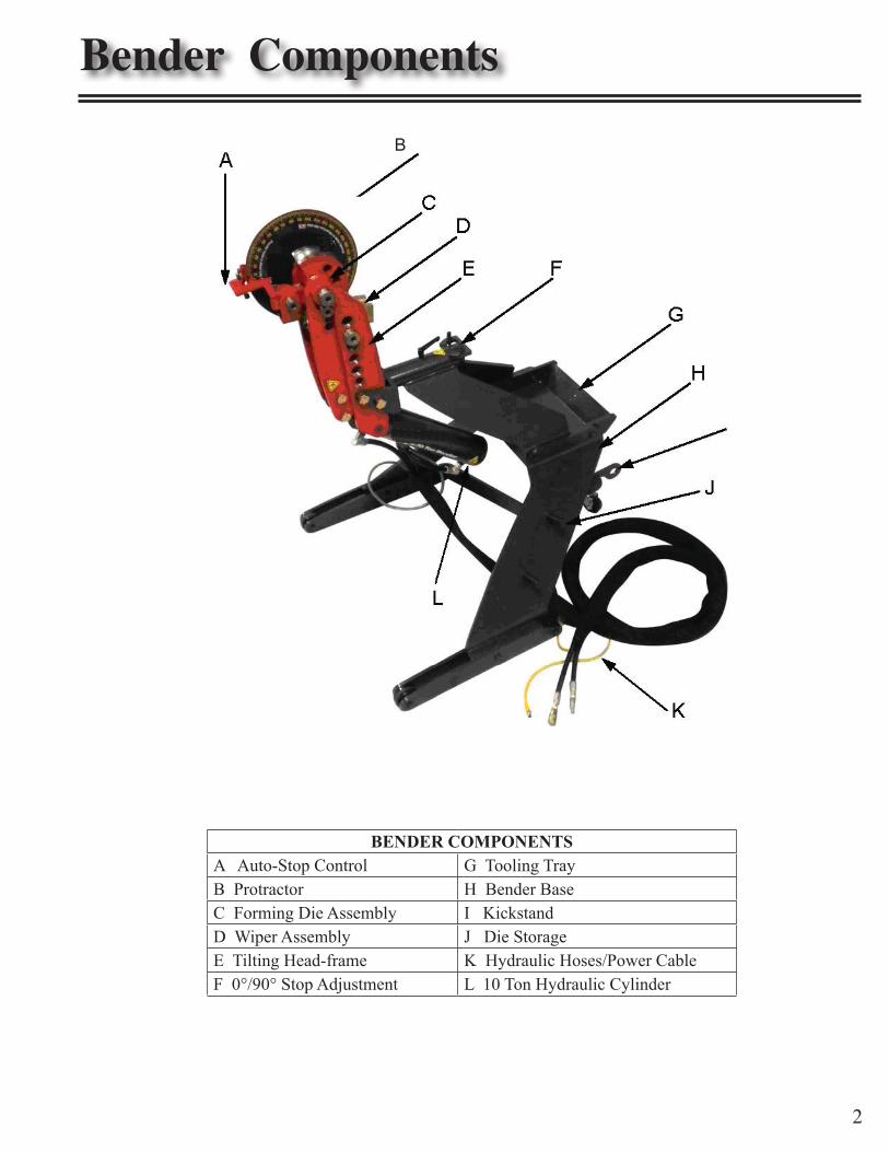
Bender Components
BENDER COMPONENTSA Auto-Stop Control G Tooling TrayB Protractor H Bender BaseC Forming Die Assembly I KickstandD Wiper Assembly J Die StorageE Tilting Head-frame K Hydraulic Hoses/Power CableF 0°/90° Stop Adjustment L 10 Ton Hydraulic Cylinder
B
2

Hydraulic Quick Connection andAccessory Controls
Bender Hydraulic Hoses andPower/Accessory Control
Hydraulic Power Sources
3
Your Cleveland Steel Tool Pipe and Tube Bender is factory assembled and tested for optimum performance when powered by The Porta Power, 5 HP, 3000psi, or The Cleveland Steel Tool 40 Ton Ironworker with the factory installed manifold.
Alternate power sources are not recommendedand may compromise machine operation,
machine hydraulic warranty and operator safety.
Follow electrical connection installation instructions as set forth within the sections of the Installation Manual: • Electrical Installation Requirements for Ironworker Accessories at Work Station • Over-current Protection Rating Requirements • Electrical Connection to Power Supply • Starter box Wiring
Powering your Bender with aCleveland Steel Tool 40 Ton Ironworker
Power selection controls are located adjacent to the starter box on the feed side of the machine. Hydraulic quick connections and accessory controls are located on the drop-off side or end cap of the machine. With the Ironworker power off, install Bender hoses, power and control:
• Install the Bender male and female accessory hydraulic hoses to the ironworker male and female quick connect hydraulic fittings. Both fittings have a detent ball setting that must be aligned to couple and uncouple hoses. • Attach the Bender male 4-pin power cable, to the 4-pin female limit switch port. • Attach the Bender control OUT / IN, male 4-pin control cable to the 4-pin female accessory control port.
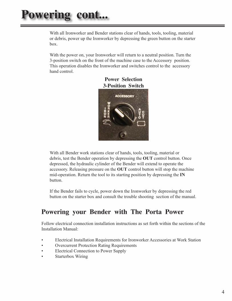
Power Selection3-Position Switch
Powering cont...With all Ironworker and Bender stations clear of hands, tools, tooling, material or debris, power up the Ironworker by depressing the green button on the starter box.
With the power on, your Ironworker will return to a neutral position. Turn the 3-position switch on the front of the machine case to the Accessory position. This operation disables the Ironworker and switches control to the accessory hand control.
4
With all Bender work stations clear of hands, tools, tooling, material or debris, test the Bender operation by depressing the OUT control button. Once depressed, the hydraulic cylinder of the Bender will extend to operate the accessory. Releasing pressure on the OUT control button will stop the machine mid-operation. Return the tool to its starting position by depressing the IN button.
If the Bender fails to cycle, power down the Ironworker by depressing the red button on the starter box and consult the trouble shooting section of the manual.
Powering your Bender with The Porta Power
Follow electrical connection installation instructions as set forth within the sections of the Installation Manual:
Electrical Installation Requirements for Ironworker Accessories at Work Station• Overcurrent Protection Rating Requirements• Electrical Connection to Power Supply• Starterbox Wiring•

The Porta-Power5HP, 3000psi Portable Power Unit
With the The Porta-Power off, install accessory hoses, power and control:
• Install the male and female Bender hydraulic hoses to the Porta-Power male and female quick connect hydraulic fittings adjacent to the starter box. Both fittings have a detent ball setting that must be aligned to couple and uncouple hoses. • Attach the Bender power cable, male 4-pin control cable to the 4-pin female limit switch port on the Porta-Power case. • Attach the Bender OUT / IN, male 4-pin control cable to the 4-pin female accessory control port on the Porta-Power case.
Power up the Porta-Power by depressing the green button on the starter box.
With all Bender stations clear of hands, tools, tooling, material or debris, test the accessory opera-tion by depressing the OUT control button. Once depressed, the hydraulic cylinder of the Bender will extend to operate the accessory. Releasing pressure on the OUT control button will stop the ma-chine mid-operation. Return the Bender to its starting position by depressing the IN button.
If the machine fails to cycle, power down the Porta Power by depressing the red button on the starter box, consult the trouble shooting section of the Operator Manual.
Powering cont...
5
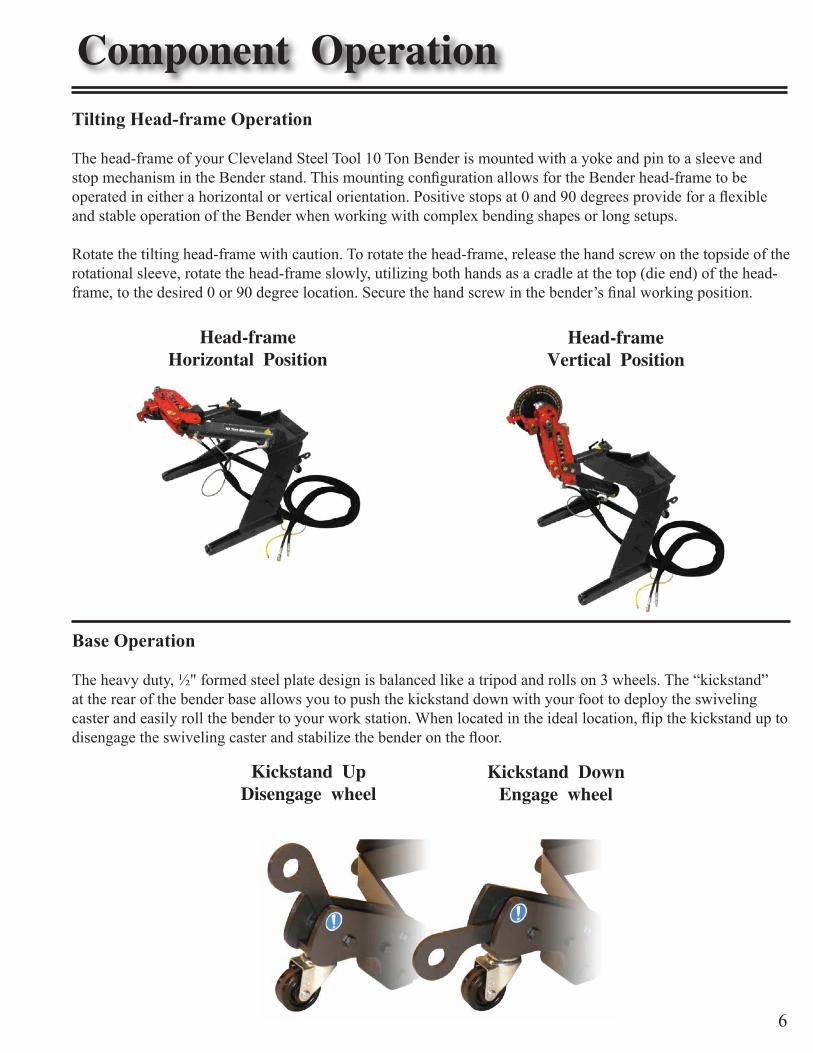
Head-frameHorizontal Position
Head-frameVertical Position
Kickstand UpDisengage wheel
Kickstand DownEngage wheel
Component OperationTilting Head-frame Operation
The head-frame of your Cleveland Steel Tool 10 Ton Bender is mounted with a yoke and pin to a sleeve and stop mechanism in the Bender stand. This mounting configuration allows for the Bender head-frame to be operated in either a horizontal or vertical orientation. Positive stops at 0 and 90 degrees provide for a flexible and stable operation of the Bender when working with complex bending shapes or long setups.
Rotate the tilting head-frame with caution. To rotate the head-frame, release the hand screw on the topside of the rotational sleeve, rotate the head-frame slowly, utilizing both hands as a cradle at the top (die end) of the head-frame, to the desired 0 or 90 degree location. Secure the hand screw in the bender’s final working position.
Base Operation
The heavy duty, ½" formed steel plate design is balanced like a tripod and rolls on 3 wheels. The “kickstand” at the rear of the bender base allows you to push the kickstand down with your foot to deploy the swiveling caster and easily roll the bender to your work station. When located in the ideal location, flip the kickstand up to disengage the swiveling caster and stabilize the bender on the floor.
6
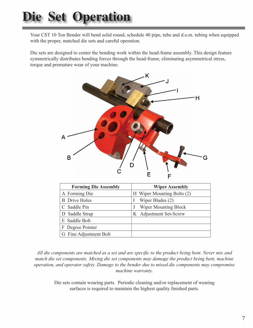
Die Set OperationYour CST 10 Ton Bender will bend solid round, schedule 40 pipe, tube and d.o.m. tubing when equipped with the proper, matched die sets and careful operation.
Die sets are designed to center the bending work within the head-frame assembly. This design feature symmetrically distributes bending forces through the head-frame, eliminating asymmetrical stress, torque and premature wear of your machine.
Forming Die Assembly Wiper AssemblyA Forming Die H Wiper Mounting Bolts (2)B Drive Holes I Wiper Blades (2)C Saddle Pin J Wiper Mounting BlockD Saddle Strap K Adjustment Set-ScrewE Saddle BoltF Degree PointerG Fine Adjustment Bolt
All die components are matched as a set and are specific to the product being bent. Never mix and match die set components. Mixing die set components may damage the product being bent, machine
operation, and operator safety. Damage to the bender due to mixed die components may compromise machine warranty.
Die sets contain wearing parts. Periodic cleaning and/or replacement of wearingsurfaces is required to maintain the highest quality finished parts.
7
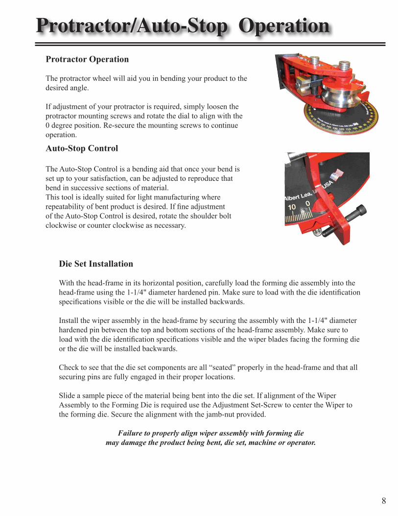
Protractor/Auto-Stop OperationProtractor Operation
The protractor wheel will aid you in bending your product to the desired angle.
If adjustment of your protractor is required, simply loosen the protractor mounting screws and rotate the dial to align with the 0 degree position. Re-secure the mounting screws to continue operation.
Auto-Stop Control
The Auto-Stop Control is a bending aid that once your bend is set up to your satisfaction, can be adjusted to reproduce that bend in successive sections of material. This tool is ideally suited for light manufacturing where repeatability of bent product is desired. If fine adjustment of the Auto-Stop Control is desired, rotate the shoulder bolt clockwise or counter clockwise as necessary.
8
Die Set Installation
With the head-frame in its horizontal position, carefully load the forming die assembly into the head-frame using the 1-1/4" diameter hardened pin. Make sure to load with the die identification specifications visible or the die will be installed backwards.
Install the wiper assembly in the head-frame by securing the assembly with the 1-1/4" diameter hardened pin between the top and bottom sections of the head-frame assembly. Make sure to load with the die identification specifications visible and the wiper blades facing the forming die or the die will be installed backwards.
Check to see that the die set components are all “seated” properly in the head-frame and that all securing pins are fully engaged in their proper locations.
Slide a sample piece of the material being bent into the die set. If alignment of the Wiper Assembly to the Forming Die is required use the Adjustment Set-Screw to center the Wiper to the forming die. Secure the alignment with the jamb-nut provided.
Failure to properly align wiper assembly with forming diemay damage the product being bent, die set, machine or operator.
Loading Material for bending
Rotate and secure the bender head-frame in either the vertical or horizontal working position. If working with long sections of material, be prepared to support your material with a material rest or roller (provided by user). Place the leading end of the material to be bent between the forming die assembly and wiper bar assembly. Capture the material with the saddle strap and saddle pin. Secure the material by tightening the saddle bolt down on the material.
Lubrication
To achieve the highest quality finished bend in your material as well as the longest life from the bearing surfaces of your die components, a liberal amount of lubrication should be applied to the bearing surfaces as follows:
Schedule 40 Pipe, Tubing and Solid Rounds• Lubricate wiper blades
Square Tubing •Lubricate tubing •Lubricate forming die
Lubricant can be mineral or vegetable-based, solid bodied or spray aerosol.
Bending
Install your material into the forming die and wiper bar assembly.• Secure the material with the matched saddle strap and 7/8" (short) saddle pin.• Secure the saddle bolt against the material to be bent with a wrench (not provided) and adequate • pressure to insure the material does not pull or slip from the forming die under bending pressure.
With your material secured between the forming die assembly and wiper bar assembly, engage the head-• frame with the die set by inserting the 7/8" (long) drive pin through the top inner head-frame, through the forming die “drive hole” and through the bottom inner head-frame.
Engage the material with the die set by activating the OUT button on the hand held controller. • Advancing the die against the material will extend the hydraulic cylinder and “push” the inner frames of the head-frame away from the outer frames. This initial movement will snug the die and material together eliminating the “slack” in the assembly.
Depress the OUT button again and the material will be drawn through the die assembly. Depress the • OUT button until your desired bend is achieved or you reach the maximum extend of the cylinder ram for the chosen drive hole.
Bending
9
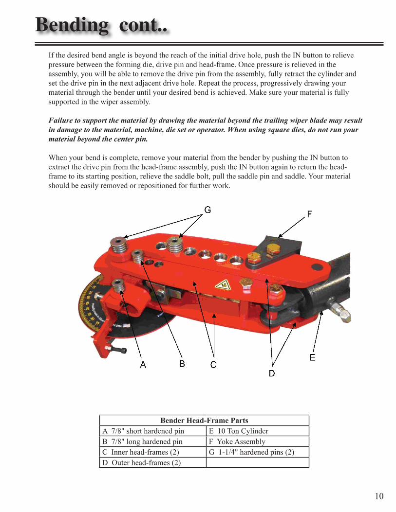
If the desired bend angle is beyond the reach of the initial drive hole, push the IN button to relieve pressure between the forming die, drive pin and head-frame. Once pressure is relieved in the assembly, you will be able to remove the drive pin from the assembly, fully retract the cylinder and set the drive pin in the next adjacent drive hole. Repeat the process, progressively drawing your material through the bender until your desired bend is achieved. Make sure your material is fully supported in the wiper assembly.
Failure to support the material by drawing the material beyond the trailing wiper blade may result in damage to the material, machine, die set or operator. When using square dies, do not run your material beyond the center pin.
When your bend is complete, remove your material from the bender by pushing the IN button to extract the drive pin from the head-frame assembly, push the IN button again to return the head-frame to its starting position, relieve the saddle bolt, pull the saddle pin and saddle. Your material should be easily removed or repositioned for further work.
Bender Head-Frame PartsA 7/8" short hardened pin E 10 Ton CylinderB 7/8" long hardened pin F Yoke AssemblyC Inner head-frames (2) G 1-1/4" hardened pins (2)D Outer head-frames (2)
Bending cont..
10
Troubleshooting
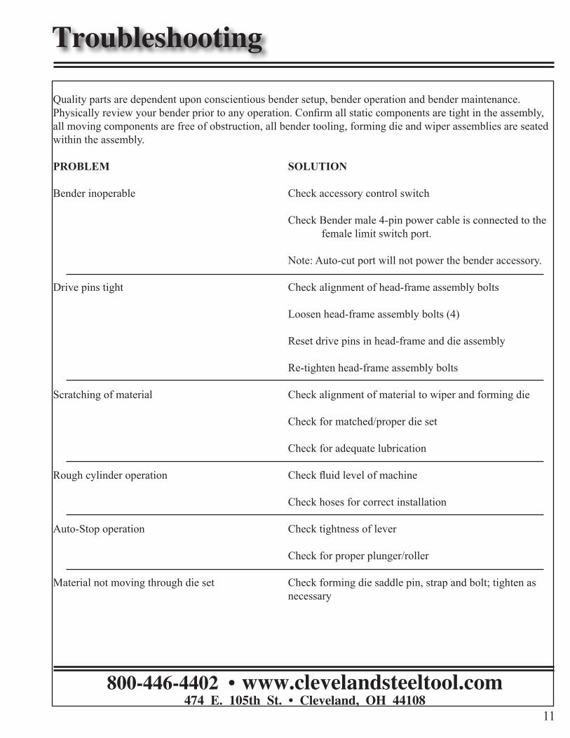
Quality parts are dependent upon conscientious bender setup, bender operation and bender maintenance. Physically review your bender prior to any operation. Confirm all static components are tight in the assembly, all moving components are free of obstruction, all bender tooling, forming die and wiper assemblies are seated within the assembly.
PROBLEM SOLUTION
Bender inoperable Check accessory control switch Check Bender male 4-pin power cable is connected to the female limit switch port.
Note: Auto-cut port will not power the bender accessory.
Drive pins tight Check alignment of head-frame assembly bolts
Loosen head-frame assembly bolts (4)
Reset drive pins in head-frame and die assembly
Re-tighten head-frame assembly bolts
Scratching of material Check alignment of material to wiper and forming die Check for matched/proper die set
Check for adequate lubrication
Rough cylinder operation Check fluid level of machine Check hoses for correct installation
Auto-Stop operation Check tightness of lever
Check for proper plunger/roller
Material not moving through die set Check forming die saddle pin, strap and bolt; tighten as necessary
11
800-446-4402 • www.clevelandsteeltool.com474 E. 105th St. • Cleveland, OH 44108