100g psm4 power, size & cost estimates &...
TRANSCRIPT
100G PSM4 Power, Size & Cost Estimates & Comparisons
John Petrilla: Avago TechnologiesJanuary 2013
Phoenix 2013 Avago Technologies: 100G PSM4 Power, Size & Cost Estimates & Comparisons
Supporters
2
David Cunningham Avago TechnologiesBrian Welch LuxteraChris Bergey LuxteraJon Anderson Oclaro
Phoenix 2013 Avago Technologies: 100G PSM4 Power, Size & Cost Estimates & Comparisons
Presentation Overview
Power consumption, size and cost of a proposed solution (100G PSM4) for the 500 m SMF objective are compared with an expected 100GBASE-LR4 implementation.
• Block diagrams (high speed signal elements) are presented for 100G variants: 100G SR10, 100G SR4, 100G LR4 and 100G PSM4.
• Power consumption and size estimates are based on experience with 100G SR10 and 40G SR4, early device results and optical link model analysis.
• Relative cost estimates are based on experience with 40G SR4, early device results and optical link model analysis.
3
Phoenix 2013 Avago Technologies: 100G PSM4 Power, Size & Cost Estimates & Comparisons
Presentation Conclusion
• The proposed 100G PSM4 transceivers offer sufficiently significant cost, density and power advantages relative to expected 100G LR4 implementations to justify a new PMD.
4
Relevant 802.3bm Objective & Criteria
Phoenix 2013 Avago Technologies: 100G PSM4 Power, Size & Cost Estimates & Comparisons
•From 802.3bm Objectives:“Define a 100 Gb/s PHY for operation up to at least 500 m of SMF”
•From 802.3bm Distinct Identity:“The amendment will enable new PHY types over SMF which consist of the existing 100GBASELR4 and 100GBASE-ER4 optical PMDs with four electrical interconnect lanes in each direction.The amendment will define a new 100 Gb/s SMF PMD in addition to these if it can be shown that a SMF PMD with a shorter reach than 100GBASE-LR4 has sufficient cost, density, or power difference to justify an additional SMF PMD type.”
5
100G 10 Lane & 4 Lane Parallel MM Transceivers
Phoenix 2013 Avago Technologies: 100G PSM4 Power, Size & Cost Estimates & Comparisons
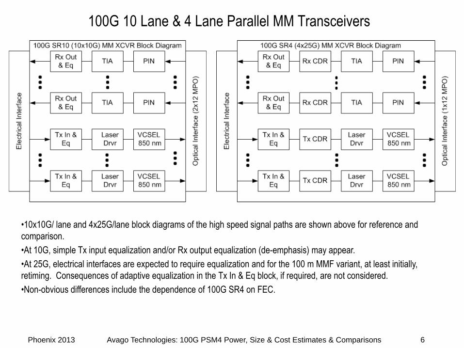
•10x10G/ lane and 4x25G/lane block diagrams of the high speed signal paths are shown above for reference and comparison.•At 10G, simple Tx input equalization and/or Rx output equalization (de-emphasis) may appear.•At 25G, electrical interfaces are expected to require equalization and for the 100 m MMF variant, at least initially, retiming. Consequences of adaptive equalization in the Tx In & Eq block, if required, are not considered.•Non-obvious differences include the dependence of 100G SR4 on FEC.
6
100G PSM4 & LR4 SM Transceivers
Phoenix 2013 Avago Technologies: 100G PSM4 Power, Size & Cost Estimates & Comparisons
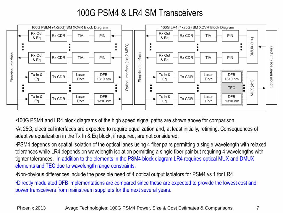
•100G PSM4 and LR4 block diagrams of the high speed signal paths are shown above for comparison.•At 25G, electrical interfaces are expected to require equalization and, at least initially, retiming. Consequences of adaptive equalization in the Tx In & Eq block, if required, are not considered.•PSM4 depends on spatial isolation of the optical lanes using 4 fiber pairs permitting a single wavelength with relaxed tolerances while LR4 depends on wavelength isolation permitting a single fiber pair but requiring 4 wavelengths with tighter tolerances. In addition to the elements in the PSM4 block diagram LR4 requires optical MUX and DMUX elements and TEC due to wavelength range constraints.•Non-obvious differences include the possible need of 4 optical output isolators for PSM4 vs 1 for LR4.•Directly modulated DFB implementations are compared since these are expected to provide the lowest cost and power transceivers from mainstream suppliers for the next several years.
7
100G PSM4: Key Tx Link Model Attributes (each lane)
Phoenix 2013 Avago Technologies: 100G PSM4 Power, Size & Cost Estimates & Comparisons 8
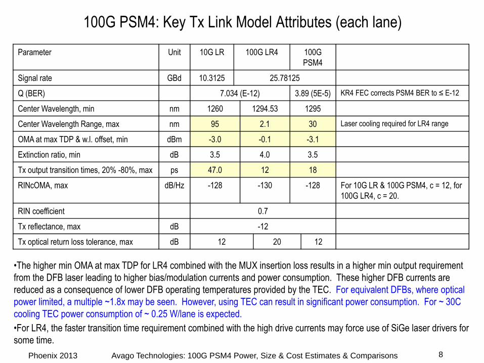
•The higher min OMA at max TDP for LR4 combined with the MUX insertion loss results in a higher min output requirement from the DFB laser leading to higher bias/modulation currents and power consumption. These higher DFB currents are reduced as a consequence of lower DFB operating temperatures provided by the TEC. For equivalent DFBs, where optical power limited, a multiple ~1.8x may be seen. However, using TEC can result in significant power consumption. For ~ 30C cooling TEC power consumption of ~ 0.25 W/lane is expected.•For LR4, the faster transition time requirement combined with the high drive currents may force use of SiGe laser drivers for some time.
Parameter Unit 10G LR 100G LR4 100G PSM4
Signal rate GBd 10.3125 25.78125
Q (BER) 7.034 (E-12) 3.89 (5E-5) KR4 FEC corrects PSM4 BER to ≤ E-12
Center Wavelength, min nm 1260 1294.53 1295
Center Wavelength Range, max nm 95 2.1 30 Laser cooling required for LR4 range
OMA at max TDP & w.l. offset, min dBm -3.0 -0.1 -3.1
Extinction ratio, min dB 3.5 4.0 3.5
Tx output transition times, 20% -80%, max ps 47.0 12 18
RINcOMA, max dB/Hz -128 -130 -128 For 10G LR & 100G PSM4, c = 12, for 100G LR4, c = 20.
RIN coefficient 0.7
Tx reflectance, max dB -12
Tx optical return loss tolerance, max dB 12 20 12
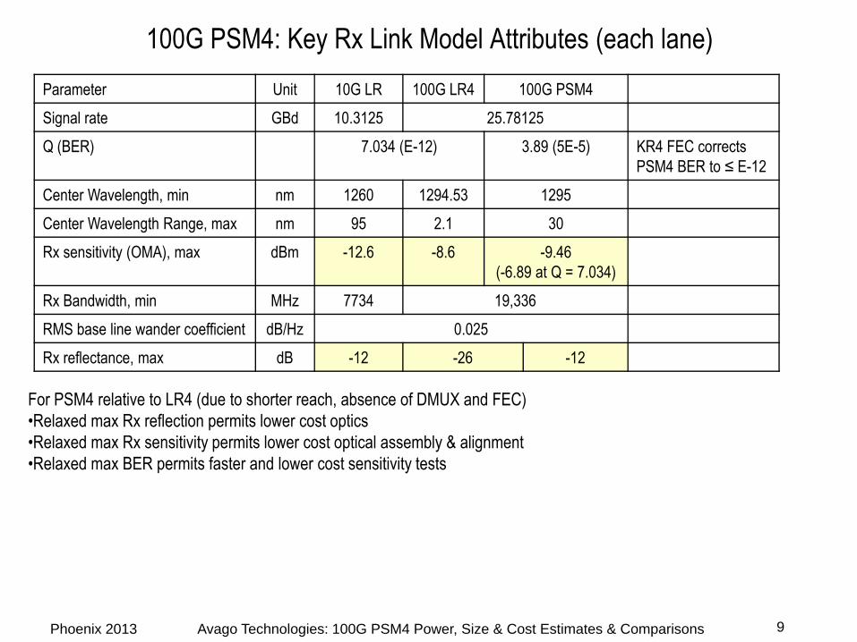
100G PSM4: Key Rx Link Model Attributes (each lane)
Phoenix 2013 Avago Technologies: 100G PSM4 Power, Size & Cost Estimates & Comparisons 9
For PSM4 relative to LR4 (due to shorter reach, absence of DMUX and FEC)•Relaxed max Rx reflection permits lower cost optics•Relaxed max Rx sensitivity permits lower cost optical assembly & alignment•Relaxed max BER permits faster and lower cost sensitivity tests
Parameter Unit 10G LR 100G LR4 100G PSM4Signal rate GBd 10.3125 25.78125Q (BER) 7.034 (E-12) 3.89 (5E-5) KR4 FEC corrects
PSM4 BER to ≤ E-12Center Wavelength, min nm 1260 1294.53 1295Center Wavelength Range, max nm 95 2.1 30Rx sensitivity (OMA), max dBm -12.6 -8.6 -9.46
(-6.89 at Q = 7.034)Rx Bandwidth, min MHz 7734 19,336RMS base line wander coefficient dB/Hz 0.025Rx reflectance, max dB -12 -26 -12
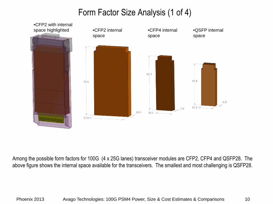
Form Factor Size Analysis (1 of 4)
Phoenix 2013 Avago Technologies: 100G PSM4 Power, Size & Cost Estimates & Comparisons
Among the possible form factors for 100G (4 x 25G lanes) transceiver modules are CFP2, CFP4 and QSFP28. The above figure shows the internal space available for the transceivers. The smallest and most challenging is QSFP28.
10
•CFP2 with internal space highlighted •CFP2 internal
space•CFP4 internal space
•QSFP internal space
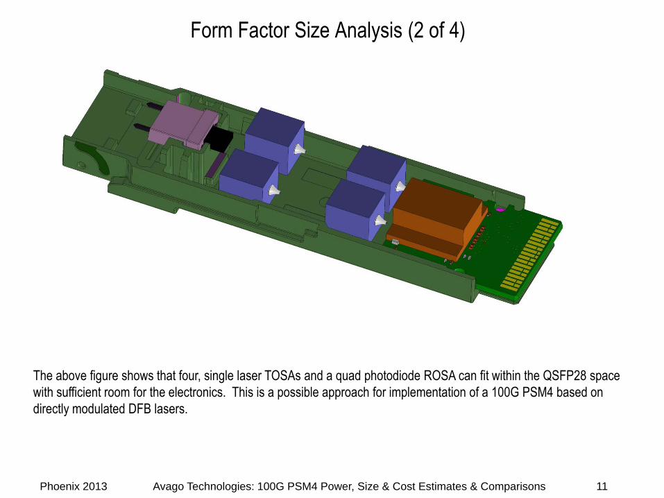
Form Factor Size Analysis (2 of 4)
Phoenix 2013 Avago Technologies: 100G PSM4 Power, Size & Cost Estimates & Comparisons
The above figure shows that four, single laser TOSAs and a quad photodiode ROSA can fit within the QSFP28 space with sufficient room for the electronics. This is a possible approach for implementation of a 100G PSM4 based on directly modulated DFB lasers.
11
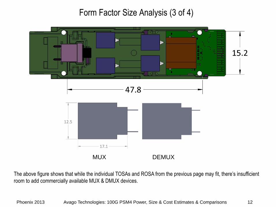
Form Factor Size Analysis (3 of 4)
Phoenix 2013 Avago Technologies: 100G PSM4 Power, Size & Cost Estimates & Comparisons
The above figure shows that while the individual TOSAs and ROSA from the previous page may fit, there’s insufficient room to add commercially available MUX & DMUX devices.
12
MUX DEMUX
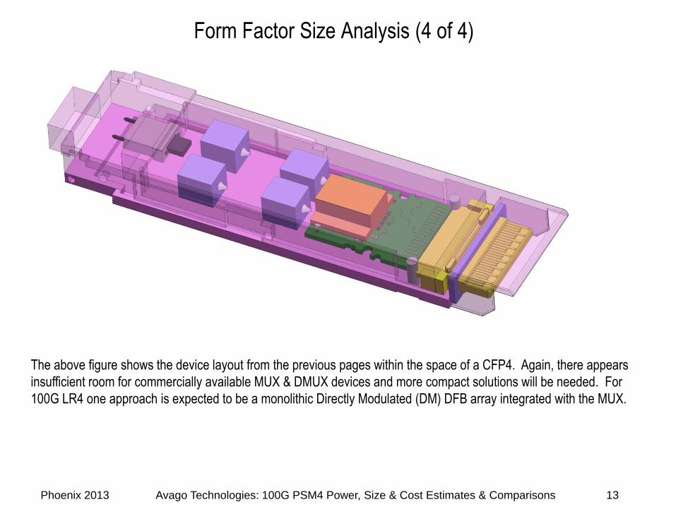
Form Factor Size Analysis (4 of 4)
Phoenix 2013 Avago Technologies: 100G PSM4 Power, Size & Cost Estimates & Comparisons
The above figure shows the device layout from the previous pages within the space of a CFP4. Again, there appears insufficient room for commercially available MUX & DMUX devices and more compact solutions will be needed. For 100G LR4 one approach is expected to be a monolithic Directly Modulated (DM) DFB array integrated with the MUX.
13
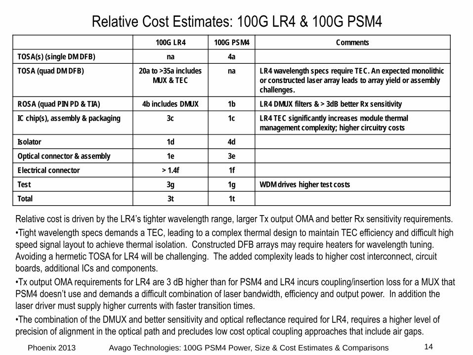
Relative Cost Estimates: 100G LR4 & 100G PSM4
Phoenix 2013 Avago Technologies: 100G PSM4 Power, Size & Cost Estimates & Comparisons 14
Relative cost is driven by the LR4’s tighter wavelength range, larger Tx output OMA and better Rx sensitivity requirements.•Tight wavelength specs demands a TEC, leading to a complex thermal design to maintain TEC efficiency and difficult high speed signal layout to achieve thermal isolation. Constructed DFB arrays may require heaters for wavelength tuning. Avoiding a hermetic TOSA for LR4 will be challenging. The added complexity leads to higher cost interconnect, circuit boards, additional ICs and components. •Tx output OMA requirements for LR4 are 3 dB higher than for PSM4 and LR4 incurs coupling/insertion loss for a MUX that PSM4 doesn’t use and demands a difficult combination of laser bandwidth, efficiency and output power. In addition the laser driver must supply higher currents with faster transition times.•The combination of the DMUX and better sensitivity and optical reflectance required for LR4, requires a higher level of precision of alignment in the optical path and precludes low cost optical coupling approaches that include air gaps.
100G LR4 100G PSM4 Comments
TOSA(s) (single DM DFB) na 4a
TOSA (quad DM DFB) 20a to >35a includes MUX & TEC
na LR4 wavelength specs require TEC. An expected monolithic or constructed laser array leads to array yield or assembly challenges.
ROSA (quad PIN PD & TIA) 4b includes DMUX 1b LR4 DMUX filters & > 3dB better Rx sensitivity
IC chip(s), assembly & packaging 3c 1c LR4 TEC significantly increases module thermal management complexity; higher circuitry costs
Isolator 1d 4d
Optical connector & assembly 1e 3e
Electrical connector > 1.4f 1f
Test 3g 1g WDM drives higher test costs
Total 3t 1t
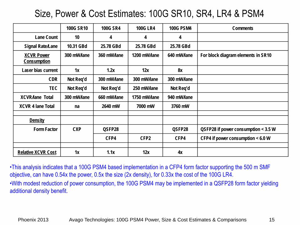
Size, Power & Cost Estimates: 100G SR10, SR4, LR4 & PSM4
Phoenix 2013 Avago Technologies: 100G PSM4 Power, Size & Cost Estimates & Comparisons 15
100G SR10 100G SR4 100G LR4 100G PSM4 Comments
Lane Count 10 4 4 4
Signal Rate/Lane 10.31 GBd 25.78 GBd 25.78 GBd 25.78 GBd
XCVR Power Consumption
300 mW/lane 360 mW/lane 1200 mW/lane 640 mW/lane For block diagram elements in SR10
Laser bias current 1x 1.2x 12x 8x
CDR Not Req’d 300 mW/lane 300 mW/lane 300 mW/lane
TEC Not Req’d Not Req’d 250 mW/lane Not Req’d
XCVR/lane Total 300 mW/lane 660 mW/lane 1750 mW/lane 940 mW/lane
XCVR 4 lane Total na 2640 mW 7000 mW 3760 mW
Density
Form Factor CXP QSFP28 QSFP28 QSFP28 if power consumption < 3.5 W
CFP4 CFP2 CFP4 CFP4 if power consumption < 6.0 W
Relative XCVR Cost 1x 1.1x 12x 4x
•This analysis indicates that a 100G PSM4 based implementation in a CFP4 form factor supporting the 500 m SMF objective, can have 0.54x the power, 0.5x the size (2x density), for 0.33x the cost of the 100G LR4.•With modest reduction of power consumption, the 100G PSM4 may be implemented in a QSFP28 form factor yielding additional density benefit.