10/21/2015sme 3252: mechatronics lecture 5 1 pneumatic and hydraulic actuation system (cont.)...
TRANSCRIPT
04/20/23 SME 3252: Mechatronics Lecture 5
1
Pneumatic and hydraulic actuation system (cont.)
Lecture 5
04/20/23 SME 3252: Mechatronics Lecture 5
2
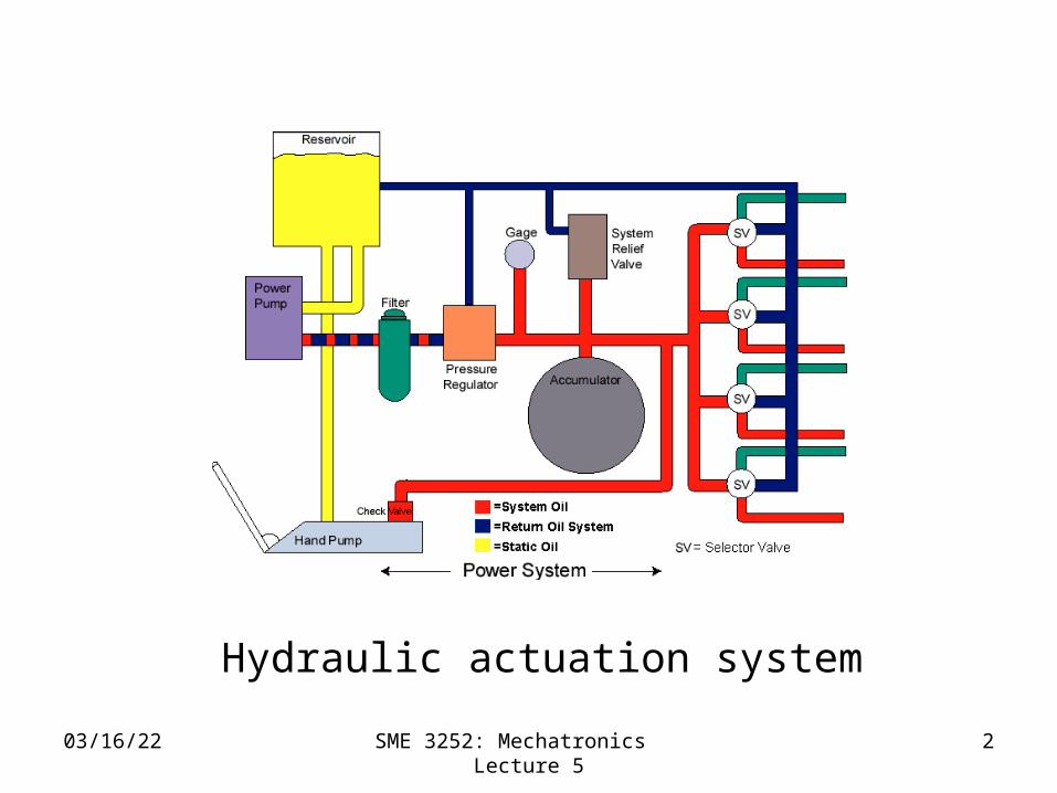
Hydraulic actuation system

04/20/23 SME 3252: Mechatronics Lecture 4
304/20/23 SME 3252: Mechatronics Lecture 4
3
Hydraulic schematic
04/20/23 SME 3252: Mechatronics Lecture 4
404/20/23 SME 3252: Mechatronics Lecture 4
4
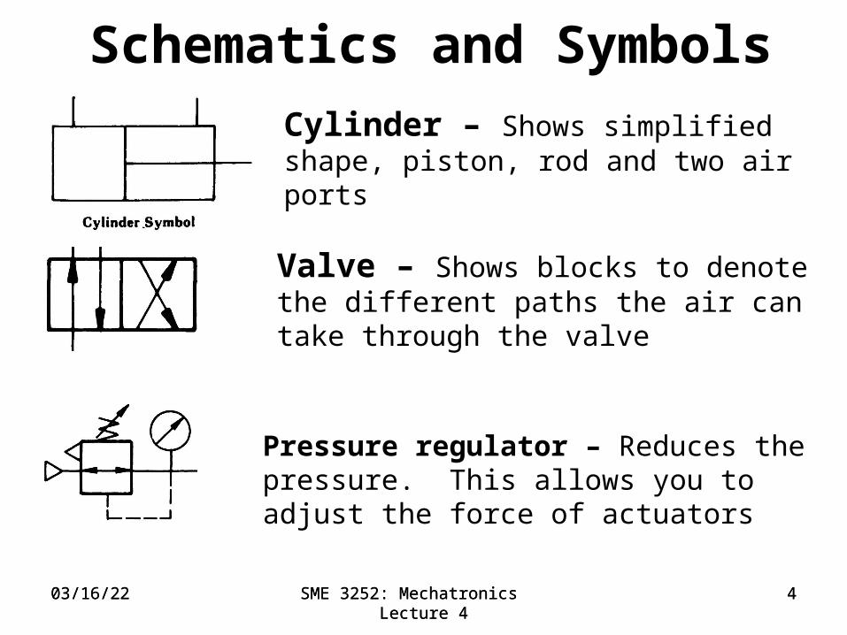
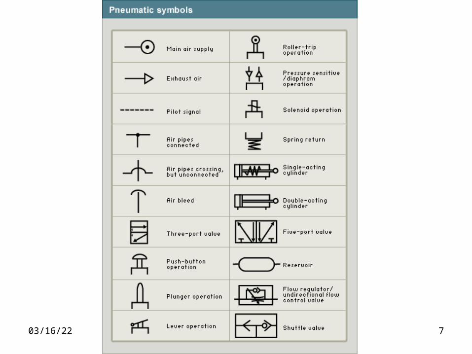
Schematics and Symbols
Valve – Shows blocks to denote the different paths the air can take through the valve
Cylinder – Shows simplified shape, piston, rod and two air ports
Pressure regulator – Reduces the pressure. This allows you to adjust the force of actuators
04/20/23 SME 3252: Mechatronics Lecture 4
504/20/23 SME 3252: Mechatronics Lecture 4
5
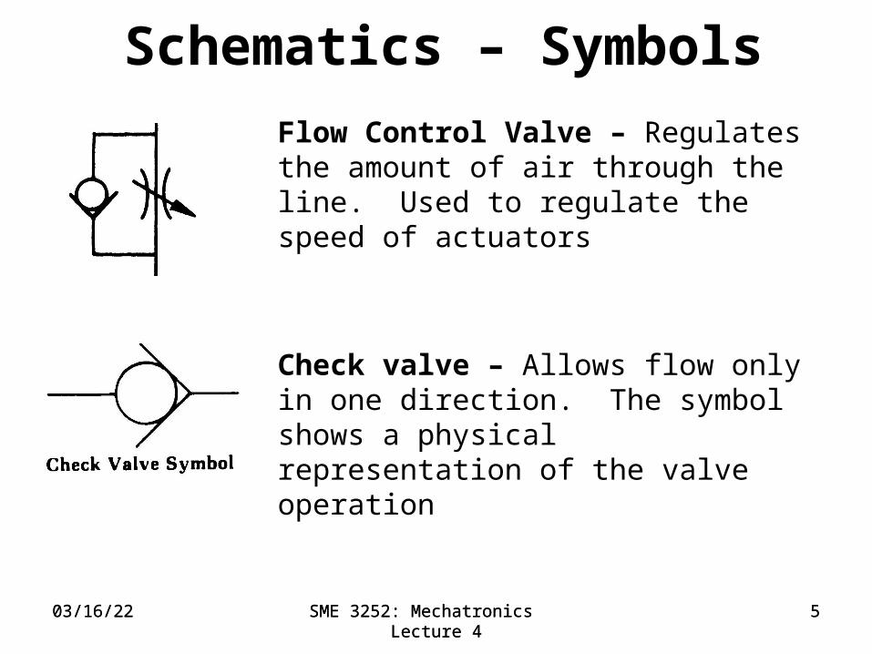
Schematics – Symbols
Flow Control Valve – Regulates the amount of air through the line. Used to regulate the speed of actuators
Check valve – Allows flow only in one direction. The symbol shows a physical representation of the valve operation

04/20/23 SME 3252: Mechatronics Lecture 4
604/20/23 SME 3252: Mechatronics Lecture 4
604/20/23 SME 3252: Mechatronics Lecture 4
6
Schematics – Symbols
Reservoir –
Air service unit –
04/20/23 SME 3252: Mechatronics Lecture 4
7
04/20/23 SME 3252: Mechatronics Lecture 4
8
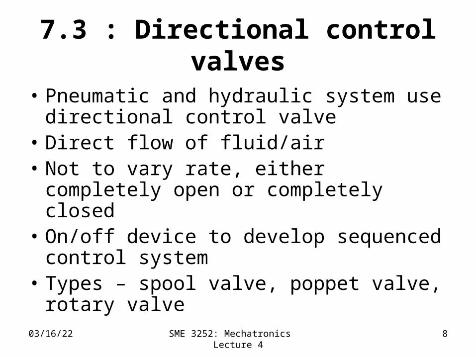
7.3 : Directional control valves
• Pneumatic and hydraulic system use directional control valve
• Direct flow of fluid/air • Not to vary rate, either completely
open or completely closed• On/off device to develop sequenced
control system• Types – spool valve, poppet valve,
rotary valve
04/20/23 SME 3252: Mechatronics Lecture 4
9
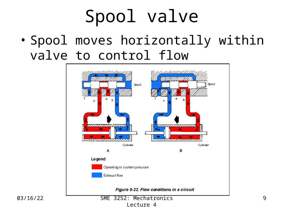
Spool valve• Spool moves horizontally within
valve to control flow

04/20/23 SME 3252: Mechatronics Lecture 4
10
Figure 7.5 Spool valve

04/20/23 SME 3252: Mechatronics Lecture 4
11
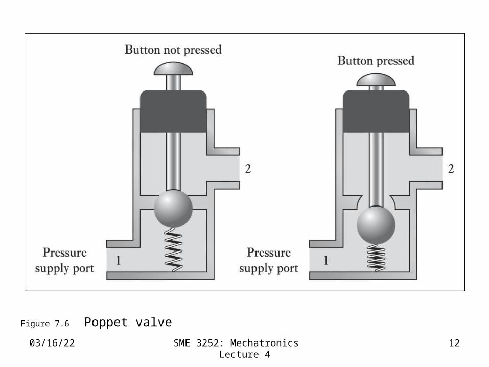
Poppet valve
• Normally in closed condition• Ball, disk or cone are used to control
flow
04/20/23 SME 3252: Mechatronics Lecture 4
12
Figure 7.6 Poppet valve

04/20/23 SME 3252: Mechatronics Lecture 4
13
7.3.1: Valve Symbols• Symbols for valve consists of square
for each switching position• E.g. two-position valve has 2
squares, three-position valve has 3 squares
• Arrow head lines – indicate directions of flow in each position
• Blocked off line – closed flow lines• Initial position - connection to ports
04/20/23 SME 3252: Mechatronics Lecture 4
14
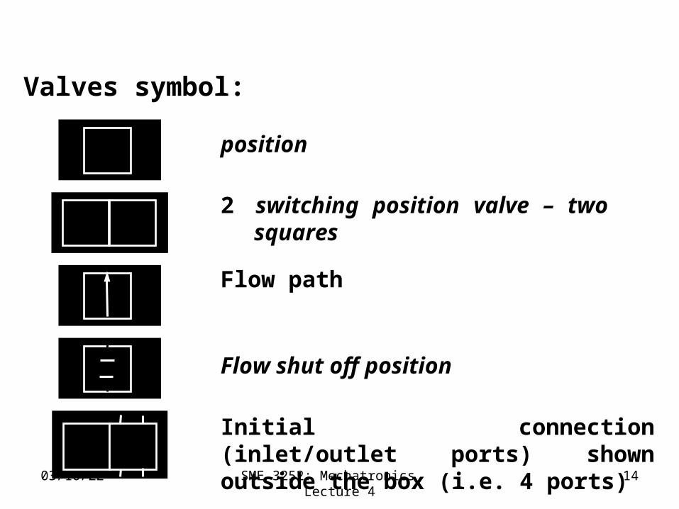
Valves symbol:
position
2 switching position valve – two squares
Flow path
Flow shut off position
Initial connection (inlet/outlet ports) shown outside the box (i.e. 4 ports)

04/20/23 SME 3252: Mechatronics Lecture 4
15
Figure 7.7 (a) Flow path, (b) flow shut-off, (c) initial connections

04/20/23 SME 3252: Mechatronics Lecture 4
16
Valve actuation symbolThere are various ways the valves can be actuated:
General /manual
“push-button”
“pull” “lever”
“pedal “spring”
“roller” “solenoid”
pneumatic

04/20/23 SME 3252: Mechatronics Lecture 4
17
Figure 7.8 Valve actuation symbols

04/20/23 SME 3252: Mechatronics Lecture 4
18
04/20/23 SME 3252: Mechatronics Lecture 4
19
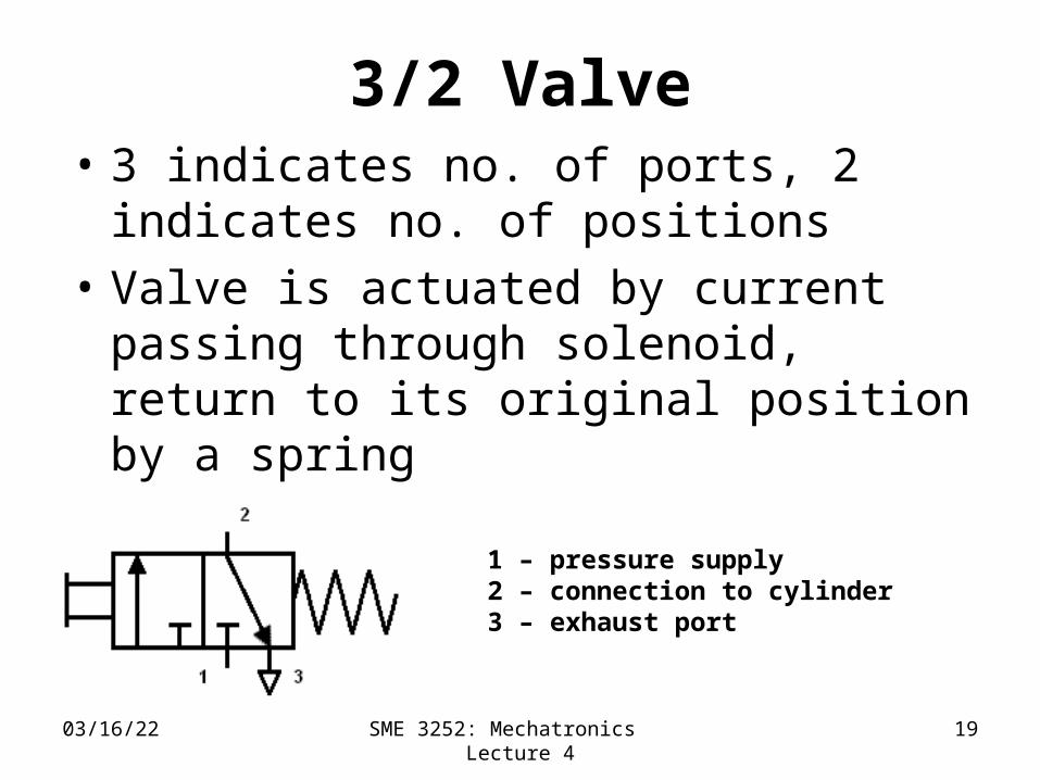
3/2 Valve• 3 indicates no. of ports, 2 indicates
no. of positions• Valve is actuated by current passing
through solenoid, return to its original position by a spring
1 – pressure supply2 – connection to cylinder3 – exhaust port

Lift system
• Refer to figure 7.11 page 157 – application of valves in a pneumatic lift
• Two push button 2/2 valves are used
• Button on the up valve is pressed – load is lifted
• Button on the down valve is pressed, load is lowered
04/20/23 SME 3252: Mechatronics Lecture 4
20
04/20/23 SME 3252: Mechatronics Lecture 4
21
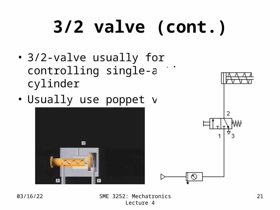
3/2 valve (cont.)
• 3/2-valve usually for controlling single-acting cylinder
• Usually use poppet valve
04/20/23 SME 3252: Mechatronics Lecture 4
22
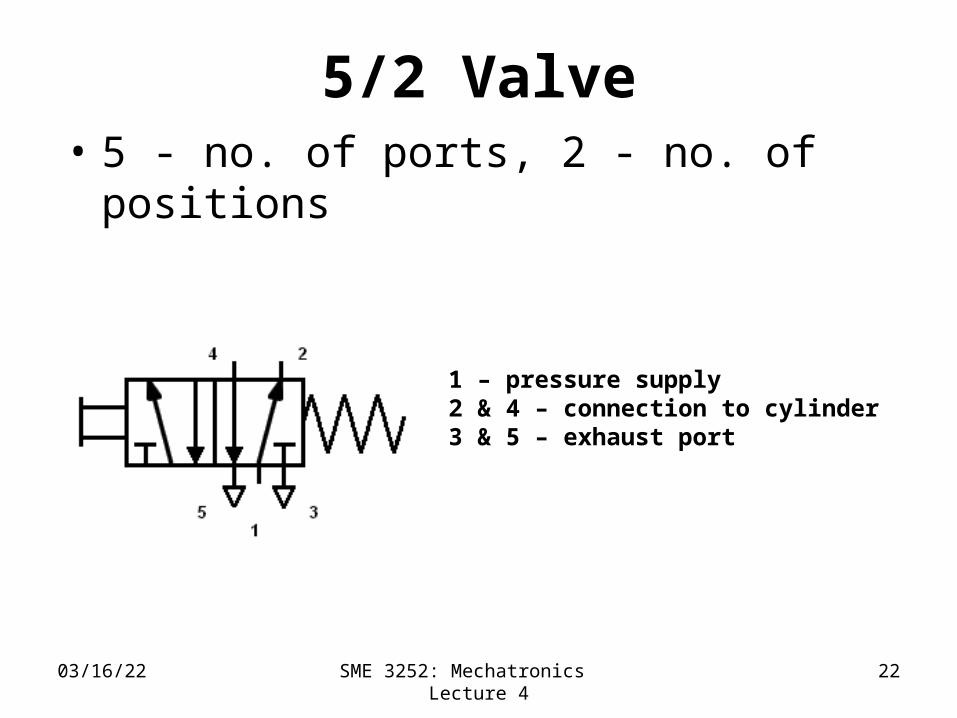
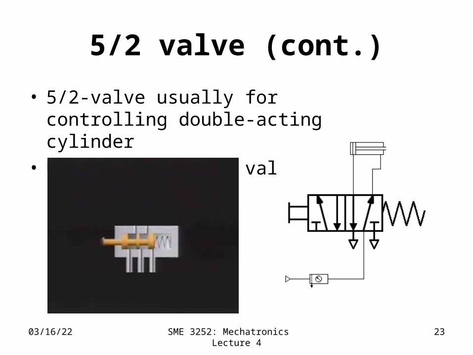
5/2 Valve• 5 - no. of ports, 2 - no. of positions
1 – pressure supply2 & 4 – connection to cylinder3 & 5 – exhaust port
04/20/23 SME 3252: Mechatronics Lecture 4
23
5/2 valve (cont.)
• 5/2-valve usually for controlling double-acting cylinder
• Usually use slide valve
Actuator
04/20/23 SME 3252: Mechatronics Lecture 4
24

04/20/23 SME 3252: Mechatronics Lecture 4
25
5.5: Cylinders• Hydraulic or pneumatic cylinder – is
an example of linear actuator• Two types:1. Linear – using cylinder single acting cylinder double acting cylinder
2. Rotary

04/20/23 SME 3252: Mechatronics Lecture 4
26
Single-acting cylinder
• Control pressure is applied to just one side of cylinder
• This cylinder uses a spring force to move the piston in one direction
• When pressurized, the air pressure overcomes the force of the spring and compresses it

04/20/23 SME 3252: Mechatronics Lecture 5
27Single-acting cylinder

04/20/23 28
Control of a single-acting cylinder
• Current passes through solenoid – valve switches position – pressure applied to move piston
• Current ceases – valve reverts to initial position – air is vented
• Refer to Figure 7.17 of Textbook

04/20/23 SME 3252: Mechatronics Lecture 5
29
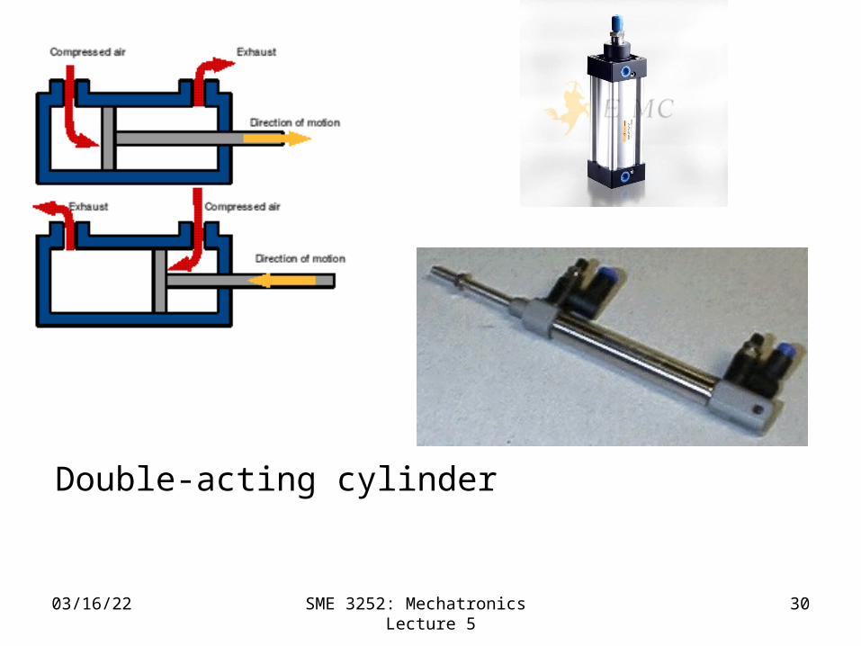
Double-acting cylinder
• Control pressures are applied to each side of piston
• A difference in pressure between two sides results in motion of piston
• Piston is able to move either direction along cylinder due to high pressure signals
04/20/23 SME 3252: Mechatronics Lecture 5
30
Double-acting cylinder

04/20/23 SME 3252: Mechatronics Lecture 5
31

04/20/23 SME 3252: Mechatronics Lecture 5
32
Control of a double-acting cylinder
• Refer to Figure 5.19 of textbook
Solenoid activated, piston extends
04/20/23 SME 3252: Mechatronics Lecture 4
33
Cylinders (cont.)
• Choice of cylinder – determined by force required to move load and speed required
• Hydraulic cylinder – capable of much large forces than pneumatic
• Pneumatic cylinder – capable of greater speed
• Force produced by cylinder

04/20/23 SME 3252: Mechatronics Lecture 4
34
Force = (Pressure)*(Area). • The pressurized air pushes against the piston
inside the cylinder• This force is dependent on two things: the
pressure of the air and the area of the piston
• If air pressure = 60 psi, dpiston = 10mm, effective surface area A = 78mm2 = 0.1217in2, Force = 7.3 lbf or 32.5 N.
• Because the piston rod reduces the effective area on one side of the piston, the pull force is not as great as the push force

04/20/23 SME 3252: Mechatronics Lecture 4
35
• For the pull force, the effective area = (Piston area) - (rod area)
• drod = 4mm, the rod area = 12.5mm2
• The effective area = 65.5mm2 • The pull force = 27.1 N or 6.09 lbf.
04/20/23 SME 3252: Mechatronics Lecture 4
36
5.6.3: Example of fluid control system
• Control level of liquid in container by controlling rate of liquid enters
• Output from sensor and signal conditioning transmitted to current to pressure converter into a pressure gauge ( 4 to 20 mA – 20 to 100 kPa)
• Actuates a pneumatic control valve to control rate of liquid allowed to flow to container

04/20/23 SME 3252: Mechatronics Lecture 4
37
Fluid control system
Flow control valve
Current to pressure converter – Fig 7.6 (b)
Signal conditioner
Sensor
- - - - - - - - - -- - - - - - - - - -
- - - - - - - -
- - - - - - - - - -- - - - - - - - - -
- - - - - - - - -
- - - - - - - - - -- - - - - - - - - -
- - -

04/20/23 SME 3252: Mechatronics Lecture 5
38
Exercises
• Differentiate between hydraulic and pneumatic cylinders
• Differentiate between single-acting and double acting cylinders
• Identify 3/2-valve, 5/2-valve, and others like 5/3-valve, 4/2-valve and etc.
• Explain the application of valve in pneumatic system
• Explain the flow control valve in application of fluid control system

04/20/23 SME 3252: Mechatronics Lecture 5
39
End of Lecture 5