10th science english-3
DESCRIPTION
http://www.ziddu.com/download/14872069/10thScienceEnglish-3.pdf.htmlTRANSCRIPT

Chapter 14
MEASUrINg INSTrUMENTS

212
PH
YS
ICS
14. Measuring InstrumentsPhysics is the most basic science, which
deals with the study of nature and natural phenomena. It is a quantitative science. Therefore physicists measure things. The ultimate test of any physical quantity is its agreement with observations and measurement of physical phenomena. One of the major contributions of physics to other sciences and society are the many measuring instruments and techniques that physics has developed. One such instrument is screw gauge.
14.1 SCrEw gAUgEScrew Gauge is an instrument to
measure the dimensions of very small objects upto 0.001 cm.
The Screw Gauge consists of ‘U’ shaped metal frame Fig. 14.1.
A hollow cylinder is attached to one end of the frame.
Grooves are cut on the inner surface of the cylinder through which a screw passes through.
On the cylinder parallel to the axis of the screw a scale is graduated in millimeter called Pitch Scale.
One end of the screw is attached to a sleeve.
The head of the sleeve is divided into 100 divisions called as the Head Scale.
The other end of the screw has a plane surface (s1).
A stud (s2) is attached to the other end of the frame, just opposite to the tip of the screw.
The screw head is provided with a ratchat arrangement (safety device) to prevent the user from exerting undue pressure.
Fig 14.1
S2 S1 Hallow Cylindrical tubeMilled Head (H)
Safety device (D)(Ratchat)
Head Scale
Index line
U-Shaped Frame pitch scale

MEASUrINg INSTrUMENTS
213
CH
AP
TE
R 1
4
Principle of the Screw gauge Screw Gauge works under the principle
of the screw. When a screw is rotated in a nut, the distance moved by the tip of the screw is directly proportional to the number of rotations.
Pitch of the screwPitch of the screw is the distance
between two screw threads. It is also equal to the distance travelled by the tip of the screw for one complete rotation of the head.
Least Count of a Screw gauge
The distance moved by the tip of the screw for a rotation of one division on the head scale is called the least count of the Screw Gauge.
Zero Error of a Screw gauge The plane surface of the screw and
the opposite plane stud on the frame are brought into contact.
Distance travelled on the pitch scale
No.of rotationsPitch =
L.C =Pitch
No.of divisions on the head scale
Fig. 14.2
No Zero Error
. If the zero of the head scale coincides with the pitch scale axis, there is no zero error.Fig. 14.2
Positive Zero Error
If the zero of the head scale lies below the pitch scale axis, the zero error is positive. If the nth division of the head scale coincides with pitch scale axis the zero error is positive.Fig.14.3
Z.E = + (n x L.C) ,
Then the Zero Correction
Z.C = – (n x L.C)
Negative Zero Error
Fig 14.4
If the Zero of the head scale lies above the pitch scale axis, the zero error is negative. If the nth division coincides with the pitch scale axis, the zero error is negative.Fig. 14.4
Z.E = – (100 – n) x L.C, Then the Zero CorrectionZ.C = + (100 – n) x L.C
Fig. 14.3
213
214
PH
YS
ICS
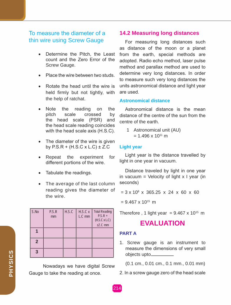
To measure the diameter of a thin wire using Screw Gauge
• Determine the Pitch, the Least count and the Zero Error of the Screw Gauge.
• Place the wire between two studs.
• Rotate the head until the wire is held firmly but not tightly, with the help of ratchat.
• Note the reading on the pitch scale crossed by the head scale (PSR) and the head scale reading coincides with the head scale axis (H.S.C).
• The diameter of the wire is given by P.S.R + (H.S.C x L.C) ± Z.C
• Repeat the experiment for different portions of the wire.
• Tabulate the readings.
• The average of the last column reading gives the diameter of the wire.
S.No P.S.Rmm
H.S.C H.S.C x L.C mm
Total ReadingP.S.R +
(H.S.C x L.C) ±Z.C mm
1
2
3
14.2 Measuring long distancesFor measuring long distances such
as distance of the moon or a planet from the earth, special methods are adopted. Radio echo method, laser pulse method and parallax method are used to determine very long distances. In order to measure such very long distances the units astronomical distance and light year are used.
Astronomical distance
Astronomical distance is the mean distance of the centre of the sun from the centre of the earth.
1 Astronomical unit (AU) = 1.496 x 10¹¹ m
Light year
Light year is the distance travelled by light in one year in vacuum.
Distance traveled by light in one year in vacuum = Velocity of light x I year (in seconds)
= 3 x 108 x 365.25 x 24 x 60 x 60
= 9.467 x 10¹⁵ m
Therefore , 1 light year = 9.467 x 10¹⁵ m
EVALUATIONPArT A
1. Screw gauge is an instrument to measure the dimensions of very small objects upto
(0.1 cm., 0.01 cm., 0.1 mm., 0.01 mm)
2. In a screw gauge zero of the head scale Nowadays we have digital Screw Gauge to take the reading at once.

MEASUrINg INSTrUMENTS
CH
AP
TE
R 1
4
lies below the pitch scale axis, the zero error is
(positive, negative, nil)
3. Screw gauge is used to measure the diameter of
( crow bar, thin wire, cricket ball )
4. One light year is equal to ( 365.25 x 24 x 60 x 60 x 3 x 108 m , 1 x 24 x 60 x 60 x 3 x 08 m , 360 x 24 x 60 x 60 x 3 x 108 m )
5. One astronomical unit is the distace between the centre of the earth and
(centre of the Moon, centre of the Sun, centre of the Mars)
PArT B
1. Correct the mistakes if any, in the following statements.
Astronomical distance is the mean distance of the surface of the sun from the surface of the earth.
Light year is the distance travelled by light in one year in vacuum at a speed of 3x10⁸ m. per minute
2. Match the items in group A with the items in group B
group A group – BSmall dimensions
Large dimensions
Long distances
Small distances
Kilo meter
Screw gauge
Scale
Light year
Altimeter
3. Fill in the blanks: Special methods adopted to determine very large distances are and
(Laser pulse method, Light year method, Radio echo method)
4. Least count of a screw gauge is an important concept related to screw gauge. What do you mean by the term least count of a screw gauge.
5. Label the following parts of the screw gauge in the given screw gauge diagram.
1. Head scale 2. Pitch scale
3. Axis 4. Ratchat
FUrTHEr rEFErENCE : Books: 1. Complete physics for IGCSE - Oxford publications.
2. Practical physics – Jerry. D. Wilson – Saunders college publishing
webste: www.complore.com
www.physlink.com
157215
Chapter 15
LAwS OF MOTION AND grAVITATION

217
CH
AP
TE
R 1
5
LAwS OF MOTION AND grAVITATION
15. Laws of motion andgravitation
In our everyday life, we observe that some effort is required to put a stationary object into motion or to stop a moving object. Normally we have to push or pull or hit an object to change its state of motion.
The concept of force is based on this push, pull or hit. No one has seen, tasted, or felt force. However, we always see or feel the effect of a force. It can only be explained by describing what happens when a force is applied to an object. Push, pull or hit may bring objects into motion, because we make a force to act on them. Therefore, force is one which changes or tends to change the state of rest or of uniform motion of a body. Force is a vector quantity. Its SI unit is newton.
15.1. BALANCED AND IMBALANCED FOrCES
Fig.15.1 shows a wooden block on a horizontal table. Two strings X and Y are tied to the two opposite faces of the block as shown.
If we apply a force by pulling the string ‘X’, the block begins to move to the right.
Similarly, if we pull the string Y, the block moves to the left. But, if the block is pulled from both the sides with equal forces the block will not move and remains stationary. Forces acting on an object which do not change the state of rest or of uniform motion of it are called balanced forces. Now let us consider a situation in which two opposite forces of different magnitudes act on the block. The block moves in the direction of the greater force. The resultant of two forces acts on an object and brings it in motion. These opposite forces are called imbalanced forces.
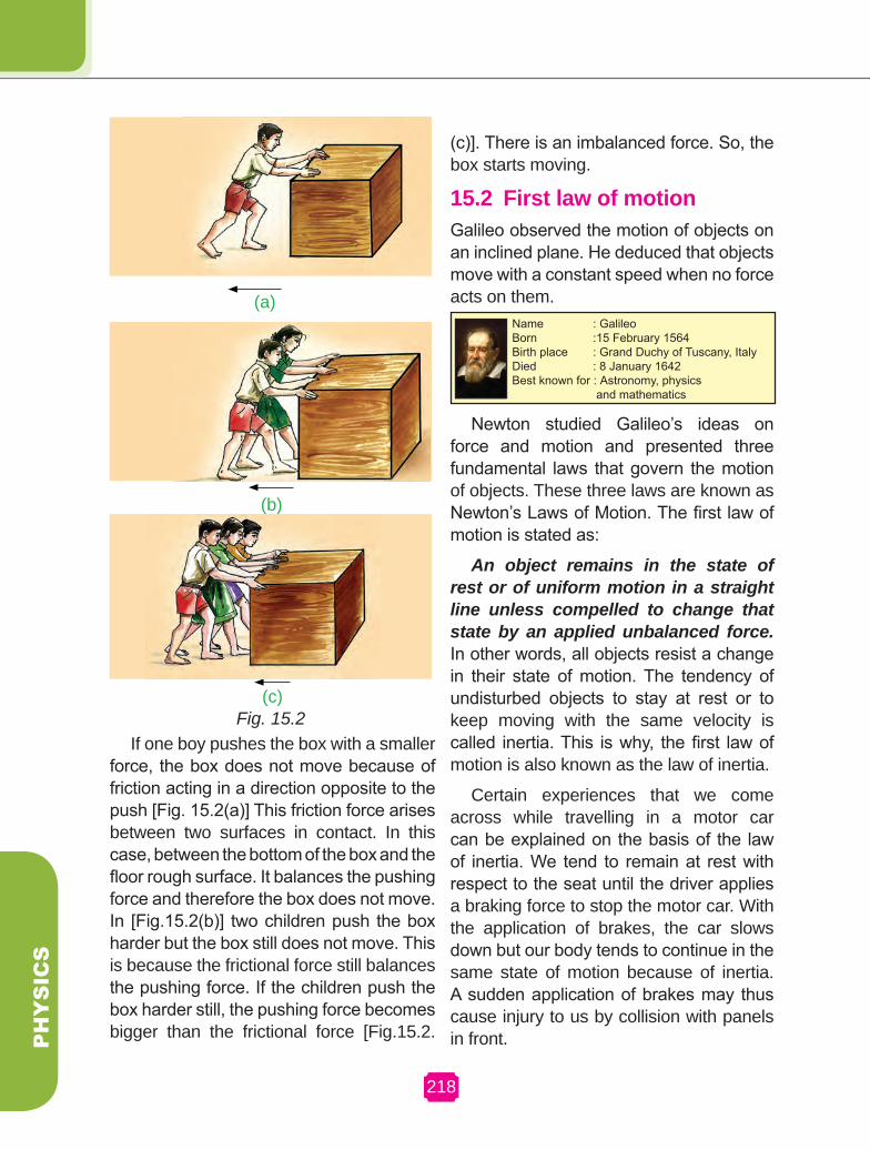
The following illustration clearly explains the concept of balanced and imbalanced forces. Some children are trying to push a box on a rough floor.
XXYY
Fig. 15.1
218
PHYSICS
If one boy pushes the box with a smaller force, the box does not move because of friction acting in a direction opposite to the push [Fig. 15.2(a)] This friction force arises between two surfaces in contact. In this case, between the bottom of the box and the floor rough surface. It balances the pushing force and therefore the box does not move. In [Fig.15.2(b)] two children push the box harder but the box still does not move. This is because the frictional force still balances the pushing force. If the children push the box harder still, the pushing force becomes bigger than the frictional force [Fig.15.2.
(c)]. There is an imbalanced force. So, the box starts moving.
15.2 First law of motionGalileo observed the motion of objects on an inclined plane. He deduced that objects move with a constant speed when no force acts on them.
Name : Galileo Born : 15 February 1564Birth place : Grand Duchy of Tuscany, ItalyDied : 8 January 1642Best known for : Astronomy, physics and mathematics
Newton studied Galileo’s ideas on force and motion and presented three fundamental laws that govern the motion of objects. These three laws are known as Newton’s Laws of Motion. The first law of motion is stated as:
An object remains in the state of rest or of uniform motion in a straight line unless compelled to change that state by an applied unbalanced force. In other words, all objects resist a change in their state of motion. The tendency of undisturbed objects to stay at rest or to keep moving with the same velocity is called inertia. This is why, the first law of motion is also known as the law of inertia.
Certain experiences that we come across while travelling in a motor car can be explained on the basis of the law of inertia. We tend to remain at rest with respect to the seat until the driver applies a braking force to stop the motor car. With the application of brakes, the car slows down but our body tends to continue in the same state of motion because of inertia. A sudden application of brakes may thus cause injury to us by collision with panels in front.
(a)
(b)
(c)Fig. 15.2

LAwS OF MOTION AND grAVITATION
219
CH
AP
TE
R 1
5
An opposite experience is encountered when we are standing in a bus which begins to move suddenly. Now we tend to fall backwards. This is because a sudden start of the bus brings motion to the bus as well as to our feet in contact with the floor of the bus. But the rest of our body opposes this motion because of its inertia.
When a motor car makes a sharp turn at a high speed, we tend to get thrown to one side. This can again be explained on the basis of the law of inertia. We tend to continue in our straight line motion. When an unbalanced force is applied by the engine to change the direction of motion of the motor car, we move to one side of the seat due to the inertia of our body.
Inertia of a body can be illustrated through the following activities.
15.3. INErTIA AND MASSAll the examples and activities given
so far, illustrate that there is a resistance
offered by an object to change its state of motion. If it is at rest, it tends to remain at rest. If it is moving it tends to keep moving. This property of an object is called inertia. Therefore the inability of a body to change its state of rest or of uniform motion by itself is called inertia.
Inertia of body depends mainly upon its mass. If we kick a foot ball, it flies away. But if we kick a stone of the same size with equal force, it hardly moves. We may, in fact get an injury in our foot. A force, that is just enough to cause a small carriage to pick up a large velocity, will produce a negligible change in the motion of a train. We say that train has more inertia than the carriage Clearly, more massive objects offer larger inertia. The inertia of an object is measured by its mass.
15.4 MOMENTUMLet us recount some observations from
our everyday life. During the game of table tennis, if a ball hits a player, it does not hurt him. On the other hand, when fast moving cricket ball hits a spectator, it may hurt him. A truck at rest does not require any attention when parked along a roadside. But a moving truck, even at a very low speed, may kill a person standing in its path. A small mass such as a bullet may kill a person when fired from a gun. These observations suggest that the impact produced by an object depends on its mass and velocity. In other words, there appears to exist some quantity of importance that combines the object’s mass and velocity. One such property called momentum was introduced by Newton. The momentum ‘p’ of an object is defined as the product of its mass ‘m’ and velocity ‘v’. That is,p=mv
Make a pile of similar carrom coins on a table as shown in Fig.15.3.
Fig. 15.3.
Attempt a sharp horizontal hit at the bottom of the pile using another carom coin or the striker. If the hit is strong enough, the bottom coin moves out quickly. Once the lowest coin is removed, the inertia of the other coins makes them ‘fall’ vertically on the table.
ACTIVITY 15.1
219

220
PHYSICS
Momentum has both direction and magnitude. It is a vector quantity. Its direction is same as that of the velocity. The SI unit of momentum is kg ms-1.
15.5 SECOND LAw OF MOTIONLet us consider a situation in which a car with a dead battery is to be pushed along a straight road to give it a speed of 1 m s-1
which is sufficient to start its engine. If one or two persons give a sudden push (unbalanced force) to it, it hardly starts. But a continuous push over it sometime results in a gradual acceleration of the car to the required speed. It means that the change of momentum of the car is not only determined by the magnitude of the force, but also by the time during which the force is exerted. It may then also be concluded that the force necessary to change the momentum of the object depends on the time rate at which the momentum is changed.
The second law of motion states that the rate of change of momentum of an object is proportional to the applied unbalanced force in the direction of force. Suppose an object of mass ‘m’ is moving along a straight line with an initial velocity ‘u’. It is uniformly accelerated to velocity ‘v’ in time ‘t’ by the application of constant force, ‘F’ throughout the time, ‘t’.
Initial momentum of the object = mu
Final momentum of the object = mv
The change in = mv - mu = m(v - u) (1) momentum
Change of momentumRate of change = —————————of momentum time
m (v-u) = ———————— (2) t
According to Newton II law of motion, this is nothing but applied force.
m(v-u)Therefore the applied force, F = ———— t
v-u But the acceleration, a = ———— t
(which is the rate of change of velocity).
The applied force, F α ma
F = Kma (3)
‘K’ is known as the constant of proportionality. The SI unit of mass and acceleration are kg and m s-2 respectively. The unit of force is so chosen that the value of the constant ‘K’ becomes one.
Therefore, F = ma (4)
1 unit of force = (1 kg) x (1 m s-2)
The unit of force is kg m s-2 or newton which has the symbol ‘N’.
One unit of force(1N) is defined as the amount of force that produces an acceleration of 1 m s-2 in an object of 1 kg mass.
The second law of motion gives us a method to measure the force acting on an object as a product of its mass and acceleration.
LAwS OF MOTION AND grAVITATION
CH
AP
TE
R 1
5
Example:15.1A constant force acts on an object of
mass 10 kg for a duration of 4 s. It increases the objects velocity from 2 ms-1 to 8 m s-1 Find the magnitude of the applied force.
Solution:
Given, mass of the object m = 10 kg
Initial velocity u = 2 m s-1 Final velocity v = 8 m s-1 m(v - u)We know, force F = t 10 (8-2) 10 × 6F = = = 15 N 4 4
Example:15.2Which would require a greater force for
accelerating a 2 kg of mass at 4 m s-2 or a 3 kg mass at 2 m s-2?
Solution
We know, force F = ma
Given, m1 = 2 kg a1 = 4 m s-2
m2 = 3 kg a2 = 2 m s-2
Thus, F1 = m1 a1 = 2 kg × 4 m s-2 = 8 Nand F2 = m2 a2 = 3 kg × 2 m s-2 = 6 N ⇒ F1 > F2
Thus, accelerating a 2 kg mass at 4m s-2 would require a greater force.
15.6 THIrD LAw OF MOTIONLet us consider two spring balances connected together as shown in Fig. 15.4
The fixed end B of the balance is attached with a rigid support like a wall. When a force is applied through the free end of the spring balance A, it is observed that both the spring balances show the same readings on their scales. It means that the force exerted by spring balance A on balance B is equal but opposite in direction to the force exerted by the balance B on balance A. The force which balance A exerts on balance B is called action and the force of balance B on balance A is called the reaction.
Newton’s third law of motion states that for every action there is an equal and opposite reaction. It must be remembered that the action and reaction always act on two different objects.
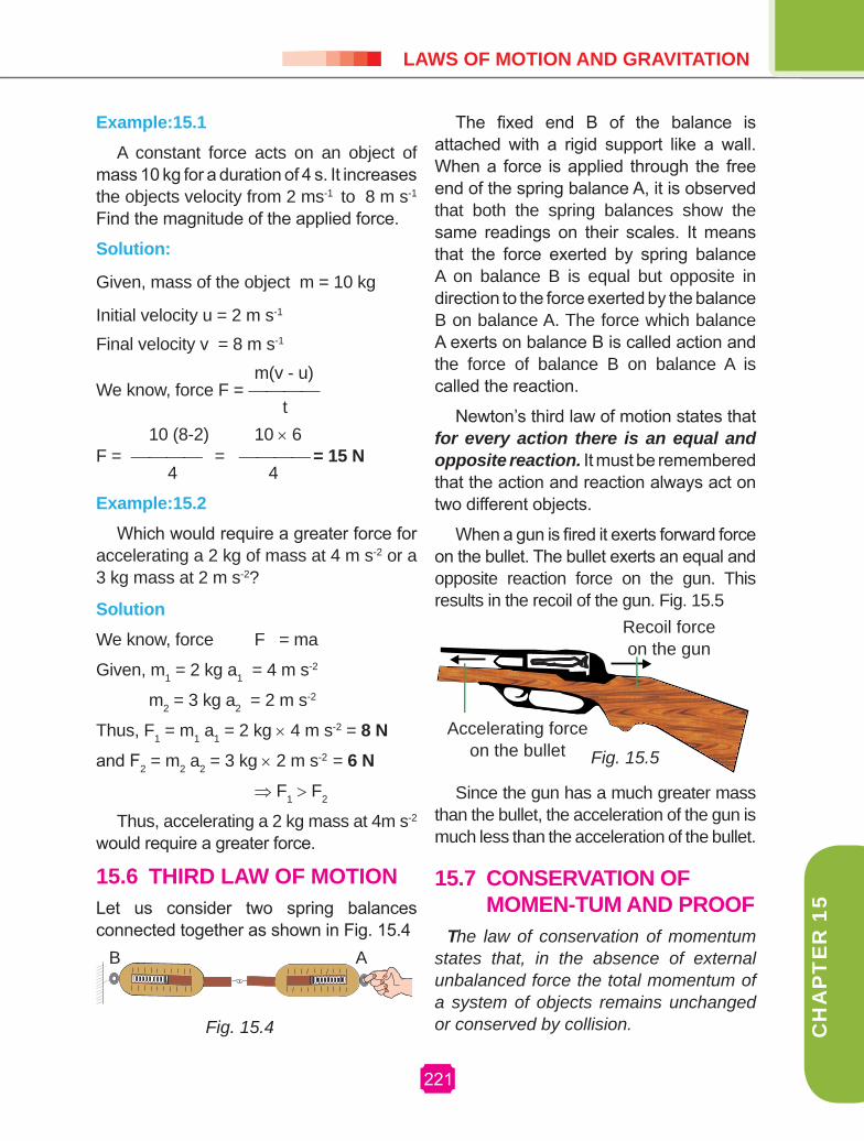
When a gun is fired it exerts forward force on the bullet. The bullet exerts an equal and opposite reaction force on the gun. This results in the recoil of the gun. Fig. 15.5
Accelerating force on the bullet
Recoil force on the gun
Since the gun has a much greater mass than the bullet, the acceleration of the gun is much less than the acceleration of the bullet.
15.7 CONSErVATION OF MOMEN-TUM AND PrOOF
The law of conservation of momentum states that, in the absence of external unbalanced force the total momentum of a system of objects remains unchanged or conserved by collision. Fig. 15.4
B A
Fig. 15.5
157221

222
PHYSICS
Consider two objects (two balls) A and B of masses ‘m1’ and ‘m2’ are traveling in the same direction along a straight line at different velocities ‘u1’ and ‘u2’ respectively Fig.15.6(a) .There are no other external unbalanced forces acting on them . Let u1 > u2 and the two balls collide with each other as shown in Fig. 15.6(b). During collision which last for time ‘t’ , the ball A exerts a force F1 on ball B , and the ball B exerts a force F2 on ball A. Let v1 and v2 be the velocities of two balls A and B after collision respectively in the same direction as before collision, Fig 15.6(c).
Before collision
During collision
(C)
After collision
According to Newton second law of motion
The force acting on B (action) F1 = mass of B X
acceleration on B.
m2 (v2-u2) F1 = ————— (1) t
The force acting
on A (reaction) F2 = mass of A X acceleration on A.
m1 (v1-u1) F2 = ————— (2) t
According to Newton’s third law of motion
F1 = – F2
From equation (1) and (2)
m2 (v2-u2) – m1 (v1-u1) ————— = ————— t t
m2 (v2 – u2) = –m1 (v1-u1)
m2v2 – m2u2 = –m1v1 + m1u1
m1v1 + m2v2 = m1u1 + m2u2
Therefore,
m1u1 + m2u2 = m1v1 + m2v2
The total momentum before collision is equal to the total momentum after collision. The total momentum of two objects remain unchanged due to collision in the absence of external force. This law holds good for any number of objects.
Fig. 15.6Take a big rubber balloon and inflate it fully.Tie its neck using a thread.
ACTIVITY 15.2

LAwS OF MOTION AND grAVITATION
223
CH
AP
TE
R 1
5
right-positive, by convention)
Recoil velocity of the pistol, = v
Total momentum of the pistol and bullet before fire, = (0.015 × 0 + 2 × 0) kg m s-1
= 0 kg m s-1
Total momentum of the pistol and bullet after fire, = (0.015 × 100 + 2 × v)
= (1.5 + 2v) kg m s-1
According to the law of conservation of momentum,
Total momentum after fire = total momentum before fire
1.5 + 2v = 0
2v = -1.5
v = -0.75 m s-1
Negative sign indicates that the direction in which the pistol would recoil is opposite to that of the bullet, that is, right to left.
15.8 MOMENT OF FOrCE AND COUPLE
Moment of a forceA force can rotate a nut when applied
by a wrench or it can open a door while the door rotates on its hinges. In addition to the tendency to move a body in the direction of the application of a force, a force also tends to rotate the body about any axis which does not intersect the line of action of the force and also not parallel to it. This tendency of rotation is called turning effect of a force or moment of the force about the given axis. The magnitude of the moment of force F about a point is defined as the product of the magnitude of force and
Example:15.3A bullet of mass 15g is horizontally fired
with a velocity 100 m s-1 from a pistol of mass 2 kg what is the recoil velocity of the pistol?
Solution: The mass of bullet, m1 = 15 g = 0.015 kg
Mass of the pistol, m2 = 2 kg
Initial velocity of the bullet, u1 = 0
Initial velocity of the pistol, u2 = 0
Final velocity of the bullet, v1 = + 100 m s-1
(The direction of bullet is taken from left to
Also using adhesive tape, fix a straw on the surface of this balloon.
• Pass a thread through the straw and hold one end of the thread in your hand or fix it on the wall.
• Ask your friend to hold the other end of the thread or fix it on a wall at some distance. This arrangement is shown in Fig.15.7
• Now remove the thread tied on the neck of the balloon. Let the air escape from the mouth of the balloon.
• Observe the direction in which the straw moves.
ACTIVITY 15.2
STRAW
BALOONAir
Fig. 15.7

224
PHYSICS
the perpendicular distance of the point from the line of action of the force.
Let us consider a force F acting at the point P on the body as shown in Fig. 15.8
Fig. 15.8
T = Fd
ForceP
Distance d
F
Then, the moment of the force F about the point O = Magnitude of the force X perpendicular distance between the direction of the force and the point about which moment is to be determined = F x d.
If the force acting on a body rotates the body in anticlockwise direction with respect to O then the moment is called anticlockwise moment. On the other hand, if the force rotates the body in clockwise direction then the moment is said to be clockwise moment. The unit of moment of the force is N m.
O
O
1
2F
F
Fig. 15.9.
As a matter of convention, an anticlockwise moment is taken as positive and a clockwise moment as negative.
CoupleThere are many examples in practice
where two forces, acting together, exert a moment or turning effect on some object. As a very simple case, suppose two strings are tied to a wheel at the points X and Y, and two equal and opposite forces, ‘F’ are exerted tangentially to the wheels (Fig. 15.10). If the wheel is pivoted at its centre O it begins to rotate about O in an anticlockwise direction.
X90
90O
F
F
Y
Fig. 1 5.10Two equal and opposite forces whose
lines of action do not coincide are said to constitute a couple in mechanics.
15.9. grAVITATION
We always observe that an object dropped from a height falls towards the earth. It is said that Newton was sitting under the tree, an apple fell on him. The fall of the apple made Newton start thinking. It is seen that a falling apple is attracted towards the

LAwS OF MOTION AND grAVITATION
CH
AP
TE
R 1
5
earth. Does the apple attract the earth? If so we do not see earth moving towards an apple. Why?
According to Newton’s Third Law of Motion, the apple does attract the earth. But according to Second Law of motion, for a given force, acceleration is inversely proportional to the mass of the object. The mass of an apple is negligibly small compared to that of the earth. So we do not see the earth moving towards the apple. We know that all planets go around the sun. Extend the above argument for all planets in our solar system. There exist a force between sun and the planets. Newton concluded that all objects in the universe attract each other. This force of attraction between objects is called the gravitational force.
Take a piece of thread. Tie a small stone at one end.
Hold the other end of the thread and whirl it round as shown in Fig. 15.11.
Note the motion of the stone.
Release the thread.
Again note the direction of motion of the stone.
ACTIVITY 15.3
It is noted that the stone describes a circular path with a velocity of constant magnitude.
15.9.1. Newton law of gravitationEvery object in the universe attracts every other object with a force which is directly proportional to the product of their masses and inversely proportional to the square of the distance between them. The force acts along the line joining the centers of two objects.
m1 m2
d
Fig. 15.12
Let two objects A and B of masses m1, m2 respectively lie at a distance ‘d’ from each other as shown in Fig.15.12. Let the force of attraction between two objects is ‘F’. According to above law,
F ∝ m1m2 (1) 1 F∝ — (2) d2 Combining (1) and (2)
m1m2 F∝ ——— (3) d2
Gm1m2 or F = ——— (4) d2
Where G is the constant of proportionality and is called the Universal gravitation constant. From eqn (4)
F.d2
G = ——— m1m2
Substituting the S.I units in this equation the unit of G is found to be N m2kg-2
The value of G is 6.673×10⁻¹¹ N m2kg-2Fig 15.11.
157225

226
PHYSICS
15.9.2 MassMass is the amount of matter present in a body (or) is a measure of how much matter an object has.
15.9.3 weightWeight is the force which a given mass feels due to the gravity at its place (or) is a measure of how strongly gravity pulls on that matter.
If you were to travel to the moon, your weight would change because the pull of the gravity is weaker there than on the earth, but your mass would stay the same because you are still made up of the same amount of matter.
Example 15.4Mass of an object is 5 kg. What is its weight on the earth?
Solution: Mass, m = 5 kg Acceleration due to gravity, g = 9.8 m s-2
Weight, w = m × g
w = 5 kg × 9.8 m s-2 = 49 N
Thus the weight of the object is, 49 NDifference between mass and weight
4. Remains the same.
Varies from place to place.
5. It is measured using physical balance.
It ismeasured using spring balance.
15.9.4 Acceleration due to gravityGalileo was the first to make a
systematic study of the motion of a body under the gravity of the Earth. He dropped various objects from leaning tower of Pisa and made analysis of their motion under gravity. He came to the conclusion that “in the absence of air, all bodies will fall at the same rate”. It is the air resistance that slows down a piece of paper or a parachute falling under gravity. If a heavy stone and a parachute are dropped where there is no air, both will fall together at the same rate.
Experiments showed that the velocity of a freely falling body under gravity increases at a constant rate.(i.e.) with a constant acceleration. The acceleration produced in a body on account of the force of gravity is called acceleration due to gravity. It is denoted by g. At a given place, the value of g is the same for all bodies irrespective of their masses. It differs from place to place on the surface of the Earth. It also varies with altitude and depth.
The value of g at sea-level and at a latitude of 45° is taken as the standard free -fall acceleration (i.e.) g=9.8 m s-2
Mass weight1. Fundamental
quantity.Derived quantity.
2. It is the amount of matter con-tained in a body.
It is the gravitational pull acting on the body.
3. Its unit is kilogram.
It is measured in newton.

LAwS OF MOTION AND grAVITATION
CH
AP
TE
R 1
5
15.9.5. Mass of earthFrom the expression g = GM/R2, the mass of the Earth can be calculated as follows: gR2
M = ——— G
M = 9.8 × (6.38 × 106)2/6.67 × 10-11
M = 5.98 × 1024 kg.
Science today Chandrayaan
Acceleration due to gravity at the surface of the earth Consider a body of mass ‘m’ on the surface of the earth as shown in Fig. 15.13.
m
mg
Earth
R
Fig.15.13
Its distance from the centre of the Earth is R (radius of the Earth).The gravitational force experienced by the GMm body is F = ——— where M is the R2
mass of the earth. From Newton’s second law of motion,
Force, F = mg
Equating the above two forces, GMm F = ——— = mg R2
Therefore, GM g = ——— R2
This equation shows that ‘g’ is independent of the mass of the body ‘m’ but, it varies with the distance from the centre of the Earth. If the Earth is assumed to be a sphere of radius R, the value of ‘g’ on the surface of the Earth is given by GM g = —— R2
Mylswamy Annadurai born on 2nd July 1958 is a household name in this part of the country .People fondly associate his name with chandrayaan to the extent it has almost become his middle name. He obtained his M.E Degree in Electronics in 1982. In the same year he joined in ISRO.
Annadurai is a leading technologist in the field of satellite system. Currently Annadurai serves as the Project Director of Chandrayaan-1 and Chandrayaan-2. He has made significant contribution to the cost effective design of Chandrayaan. Through his inspiring speeches he has become a motivating force among the Indian students.
15722227
228
PHYSICS
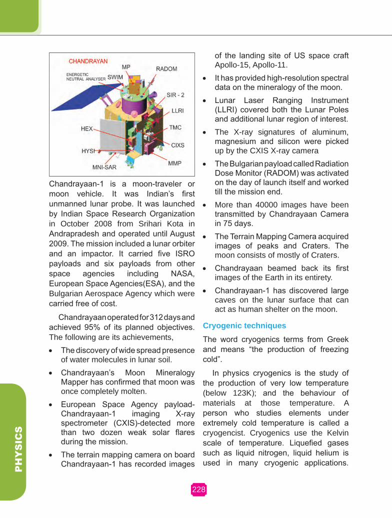
Chandrayaan-1 is a moon-traveler or moon vehicle. It was Indian’s first unmanned lunar probe. It was launched by Indian Space Research Organization in October 2008 from Srihari Kota in Andrapradesh and operated until August 2009. The mission included a lunar orbiter and an impactor. It carried five ISRO payloads and six payloads from other space agencies including NASA, European Space Agencies(ESA), and the Bulgarian Aerospace Agency which were carried free of cost.
Chandrayaan operated for 312 days and achieved 95% of its planned objectives. The following are its achievements, • The discovery of wide spread presence
of water molecules in lunar soil. • Chandrayaan’s Moon Mineralogy
Mapper has confirmed that moon was once completely molten.
• European Space Agency payload-Chandrayaan-1 imaging X-ray spectrometer (CXIS)-detected more than two dozen weak solar flares during the mission.
• The terrain mapping camera on board Chandrayaan-1 has recorded images
of the landing site of US space craft Apollo-15, Apollo-11.
• It has provided high-resolution spectral data on the mineralogy of the moon.
• Lunar Laser Ranging Instrument (LLRI) covered both the Lunar Poles and additional lunar region of interest.
• The X-ray signatures of aluminum, magnesium and silicon were picked up by the CXIS X-ray camera
• The Bulgarian payload called Radiation Dose Monitor (RADOM) was activated on the day of launch itself and worked till the mission end.
• More than 40000 images have been transmitted by Chandrayaan Camera in 75 days.
• The Terrain Mapping Camera acquired images of peaks and Craters. The moon consists of mostly of Craters.
• Chandrayaan beamed back its first images of the Earth in its entirety.
• Chandrayaan-1 has discovered large caves on the lunar surface that can act as human shelter on the moon.
Cryogenic techniquesThe word cryogenics terms from Greek and means “the production of freezing cold”.
In physics cryogenics is the study of the production of very low temperature (below 123K); and the behaviour of materials at those temperature. A person who studies elements under extremely cold temperature is called a cryogencist. Cryogenics use the Kelvin scale of temperature. Liquefied gases such as liquid nitrogen, liquid helium is used in many cryogenic applications.
LAwS OF MOTION AND grAVITATION
229
CH
AP
TE
R 1
5
Liquid nitrogen is the most commonly used element in cryogenics and is legally purchasable around the world. Liquid helium is also commonly used and allows for the lowest attainable temperature to be reached. These liquids are held in special containers called Dewar flasks which are generally about six feet tall and three feet in diameter.
The field of cryogenics advanced during world war-2. Scientist found that metals frozen to low temperature showed more resistance to wear. This is known as cryogenic hardening. The commercial cryogenic processing industry was founded in 1966 by Ed Busch; and merged several small companies later to form oldest commercial cryogenic company in the world. They originally experimented with the possibility of increasing the life of metal tools.
Cryogens like liquid nitrogen are further used for specially chilling and freezing applications.
(i) Rocket The important use of cryogenics is
cryogenic fuels. Cryogenic fuels mainly liquid hydrogen has been used as rocket fuel.
(ii) Magnetic Resonance Imaging (MRI)MRI is used to scan inner organs of
human body by penetrating very intense magnetic field. The magnetic field is generated by super conducting coils with the help of liquid helium. It can reduce the temperature of the coil to around 4k. At this low temperature very high resolution images can be obtained.(iii) Power transmission in big cities:
It is difficult to transmit power by over head cables in cities. So underground cables are used. But underground cables get heated and the resistance of the wire increases leading to wastage of power. This can be solved by cryogenics. Liquefied gases are sprayed on the cables to keep them cool and reduce their resistance.
(iv) Food Freezing:Cryogenic gases are used in
transportation of large masses of frozen food, when very large quantity of food must be transported to regions like war field, earthquake hit regions etc., they must be stored for.
(v) Vaccines:The freezing of biotechnology products
like vaccines require nitrogen freezing systems.
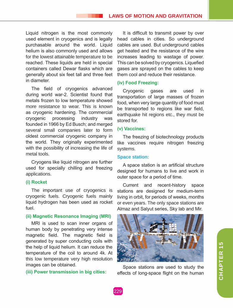
Space station:A space station is an artificial structure
designed for humans to live and work in outer space for a period of time.
Current and recent-history space stations are designed for medium-term living in orbit, for periods of weeks, months or even years. The only space stations are Almaz and Salyut series, Sky lab and Mir.
Space stations are used to study the effects of long-space flight on the human
157229

230
PHYSICS
body. It provides platforms for greater number and length of scientific studies than available on other space vehicles. Space stations have been used for both military and civilian purposes. The last military-used space station was Salyut 5, which was used by the Almaz program of the Soviet Union in 1976 and 1977.
Broadly speaking the space stations so for launched has been of two types. Salyut and Skylab have been “monolithic.” They were constructed and launched in one piece, and then manned by a crew later. As such, they generally contained all their supplies and experimental equipment when launched, and were considered “expended”, and then abandoned, when these were used up.
Starting with Salyut 6 and Salyut 7, a change was seen. These were built with two docking ports. They allowed a second crew to visit, bringing a new space craft with them.
This allowed for a crew to man the station continually, sky lab was also equipped with two docking ports, but the extra port was never utilized. The presence of the second port on the new station allowed progress supply vehicle to be docked to the station, meaning that fresh supplies could be brought to aid long-duration missions.
The second group, Mir and the International Space Station (ISS), have been modular; a core unit was launched,
and additional modules, generally with a specific role, were later added to that. (on Mir they were usually launched independently, whereas on the ISS most are brought by the Space Shuttle). This method allows for greater flexibility in operation. It removes the need for a single immensely powerful launch vehicle. These stations are also designed from the outset to have their supplies provided by logistical support, which allows for a longer lifetime at the cost of requiring regular support launches.
These stations have various issues that limit their long-term habitability, such as very low recycling rates, relatively high radiation levels and a lack of gravity. Some of these problems cause discomfort and long-term health effects.
Future space habitats may attempt to address these issues, and are intended for long-term occupation. Some designs might even accommodate large number of people, essentially “cities in space” where people would make their homes. No such design has yet been constructed, even for a small station; the current (2010) launch costs are not economically or politically viable.
The People’s Republic of China is expected to launch its space station named Tiangong 1, in the first half of 2011. This would make China the third country to launch a space station.
EVALUATIONPArT A1. The acceleration in a body is due to
___________. (balanced force, un-balanced force,
electro static force)2. The physical quantity which is equal
to rate of change of momentum is (displacement, acceleration, force, impulse)
LAwS OF MOTION AND grAVITATION
CH
AP
TE
R 1
5
5. The freezing of biotechnology products like vaccines require ________ freezing systems.
(Helium, Nitrogen, Ammonia, Chlorine)PArT – B1. From the following statements write
down that which is not applicabel to mass of an objecta. It is a fundamental quantityb. It is measured using physical
balance. c. It is measured using spring balance.
2. Fill in the blanks.a) Force = mass x acceleration, then
momentum = ____?______b) Liquid hydrogen is for rocket, then––––
–––– for MRI.3. The name of some organisations which
are associated with Chandrayan-I mission are given below. but some of them are not. List out the wrong ones.
(ISRO, BARC, NASA, ESA, WHO, ONGC)
4. Correct the mistakes, if any, in the following statements.a. One newton is the force that produces
an acceleration of 1 ms-2 in an object
of 1 gram mass.b. Action and reaction is always acting
on the same body.5. The important use of cryogenics is
cryogenic fuels. What do you mean by cryogenic fuels?
6. As a matter of convention, an anticlockwise moment is taken as ________ and a clockwise moment is taken as ________.
PArT – C1. a) Newton’s first law of motion gives a
qualitative definition of force. Justify.
10 Kg 10 Kg10 Kg20 Kg 20 Kg 20 Kg
10 m/s 5 m/s F1 F2
12m/s 4m/s
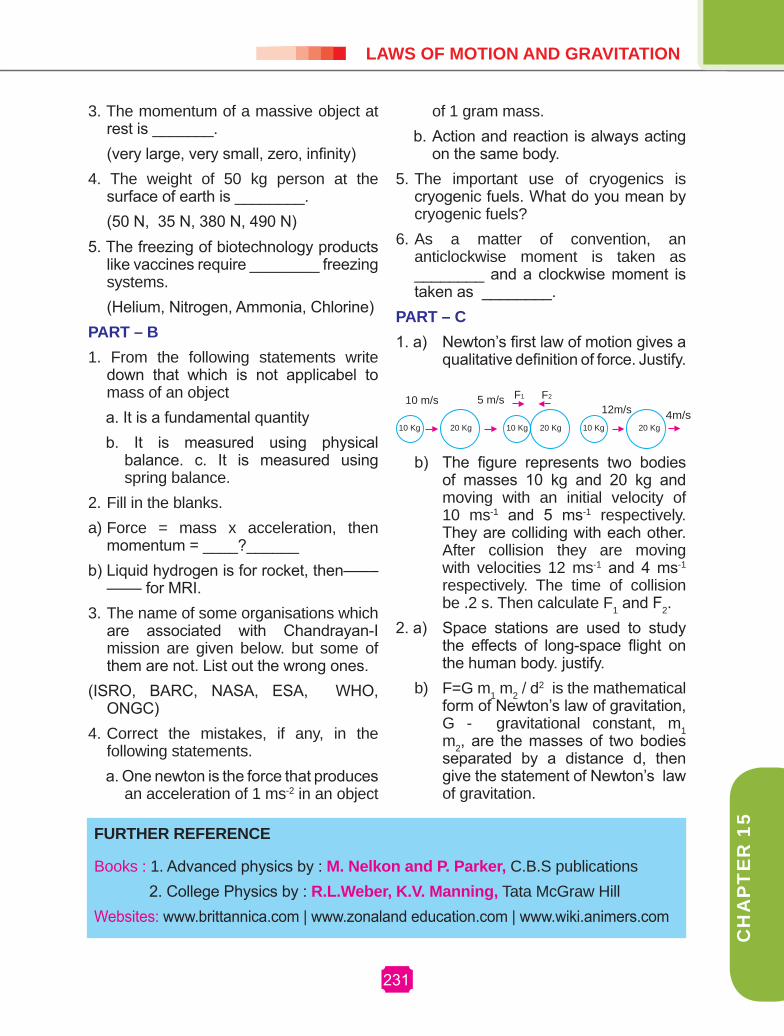
b) The figure represents two bodies of masses 10 kg and 20 kg and moving with an initial velocity of 10 ms-1 and 5 ms-1 respectively. They are colliding with each other. After collision they are moving with velocities 12 ms-1 and 4 ms-1 respectively. The time of collision be .2 s. Then calculate F1 and F2.
2. a) Space stations are used to study the effects of long-space flight on the human body. justify.
b) F=G m1 m2 / d2 is the mathematical
form of Newton’s law of gravitation, G - gravitational constant, m1 m2, are the masses of two bodies separated by a distance d, then give the statement of Newton’s law of gravitation.
3. The momentum of a massive object at rest is _______.
(very large, very small, zero, infinity)4. The weight of 50 kg person at the
surface of earth is ________. (50 N, 35 N, 380 N, 490 N)
FUrTHEr rEFErENCE
Books : 1. Advanced physics by : M. Nelkon and P. Parker, C.B.S publications 2. College Physics by : r.L.weber, k.V. Manning, Tata McGraw Hill Websites: www.brittannica.com | www.zonaland education.com | www.wiki.animers.com
157231

Chapter 16
ELECTrICITY AND ENErgY

233
CH
AP
TE
R 9
CH
AP
TE
R 1
6
ELECTrICITY AND ENErgY
16 ELECTRICITY AND ENERGY
Electricity has an important place in mod-ern society. It is a controllable and con-venient form of energy for variety of uses in homes, schools, hospitals, industries and so on. What constitutes electricity?
How does it flow in an electric circuit? What are the factors that regulate elec-tricity through an electric circuit?. In this chapter we shall attempt to answer such questions.
16.1. ELECTrIC CUrrENT AND CIrCUIT
We are familiar with air current and water current. We know that flowing water con-stitute water current in rivers. Similarly if the electric charge flows through a con-ductor (metallic wire), we say that there is an electric current in the conductor. In a
torch we know that a battery provide flow of charges or an electric current through a torch bulb to glow. We have also seen that it gives light only when it is switched on. What does a switch do? A switch makes a conducting link between the cell and the bulb. A continuous and closed path of an electric current is called an electric circuit. Now if the circuit is broken any-where the current stops flowing and the bulb does not glow.
How do we express electric current? Electric current is expressed by the amount of charge flowing through a particular area of cross section of a conductor in unit time. In other words it is the rate of flow of electric charges. In circuit using metallic wires, electrons constitute flow of charges. The direction of electric current is taken as opposite to the direction of the flow of electrons.
If a net charge Q, flows across any cross-section of a conductor in time t, then the current I through the cross-section is
I=Q/t
Name : Michael Faraday
Born : 22 September 1791
Birth place : Newington, England
Died : 25 August 1867
Best known as : Inventor of the first dynamo

234
PH
YS
ICS
The S.I unit of electric charge is cou-lomb. This is equivalent to the charge contained in nearly 6×10¹⁸ electrons. The electric current is expressed by a unit called ampere (A), named after the French Scientist.
From the above equation,
When Q = 1 C, t = 1s, I=1A.
When one coulomb of charge flows in one second across any cross section of a conductor, the current in it is one ampere. An instrument called ammeter is used to measure current in a circuit.
Example 16.1
A current of 0.75 A is drawn by a filament of an electric bulb for 10 minutes. Find the amount of electric charge that flows through the circuit.
Solution:
Given, I = 0.75 A, t = 10 minutes = 600 sWe know, Q = I × t = 0.75 A × 600 s Q = 450 C
The Fig.16.1 shows a schematic diagram of an electric circuit comprising battery, bulb, ammeter and a plug key.
16.2. ELECTrIC POTENTIAL AND POTENTIAL DIFFErENCE
What makes the electric charge to flow? ter. Charges do not flow in a copper wire by themselves, just as water in a perfectly horizontal tube does not flow. One end of the tube is connected to a tank of water. Now there is a pressure difference between the two ends of the tube. Water flows out of the other end of the tube. For flow of charges in a conducting metallic wire, the electrons move only if there is a difference of electric pressure-called potential difference-along the conductor. This difference of potential may be produced by a battery, consisting of one or more electric cells. When the cell is connected to a conducting circuit element, the potential difference sets the charges in motion in the conductor and produces an electric current.
We define the electric potential difference between two points in an electric circuit carrying some current as the work done to move a unit charge from one point to the other.
Potential difference (V) between two points = work done (W)/charge (Q).
V = W/Q
The S.I Unit of potential difference is volt (V).
1 volt = 1joule/1coulomb
One volt is the potential difference between two points in a current carrying conductor when 1 joule of work is done to move a charge of 1 coulomb from one point to the other.Fig. 16.1 Electric circuit
235
CH
AP
TE
R 9
CH
AP
TE
R 1
6
ELECTrICITY AND ENErgY
The potential difference is measured by means of an instrument called voltmeter.
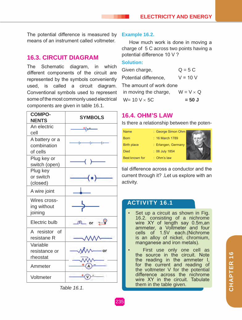
16.3. CIrCUIT DIAgrAMThe Schematic diagram, in which different components of the circuit are represented by the symbols conveniently used, is called a circuit diagram. Conventional symbols used to represent some of the most commonly used electrical components are given in table 16.1.
Example 16.2.How much work is done in moving a
charge of 5 C across two points having a potential difference 10 V ?Solution:Given charge, Q = 5 CPotential difference, V = 10 VThe amount of work done in moving the charge, W = V × Q W= 10 V × 5C = 50 J
16.4. OHM’S LAw
Table 16.1.
Is there a relationship between the poten-
tial difference across a conductor and the current through it? .Let us explore with an activity.
COMPO-NENTS SYMBOLS
An electric cellA battery or a combination of cellsPlug key or switch (open)Plug key or switch (closed)A wire joint
Wires cross-ing without joining
Electric bulb
A resistor of resistane RVariable resistance or rheostat
Ammeter
Voltmeter
• Set up a circuit as shown in Fig. 16.2. consisting of a nichrome wire XY of length say 0.5m,an ammeter, a Voltmeter and four cells of 1.5V each.(Nichrome is an alloy of nickel, chromium, manganese and iron metals).
• First use only one cell as the source in the circuit. Note the reading in the ammeter I, for the current and reading of the voltmeter V for the potential difference across the nichrome wire XY in the circuit. Tabulate them in the table given.
ACTIvITY 16.1
Name : George Simon Ohm
Born : 16 March 1789
Birth place : Erlangen, Germany
Died : 06 July 1854
Best known for : Ohm’s law

236
PH
YS
ICS
S.No Number of cells used in the circuit
Current through the nichrome wireI (ampere)
Potential difference across the nichrome wire. V (volt)
V/I(volt/ampere)
Ω
1.2.3.4.5.6.
In this activity you will find the ratio V/I is a constant.
In 1827, a German Physicist George Simon Ohm found out the relationship between the current I flowing in a metal-
ACTIvITY
Repeat the above steps using two, three cells and then four cells in the circuit separately.
• Calculate the ratio of V to I for each pair of potential difference V and current I.
Fig. 16.2
lic wire and the potential difference across its terminals.
Ohm’s law states that at constant temperature the steady current (I) flowing through a conductor is directly proportional to the potential difference (V) between its ends.
V∝ I (or) V/I=constant.
Example 16.3The potential difference between the
terminals of an electric heater is 60 V when it draws a current of 5 A from the source. What current will the heater draw if the potential difference is increased to 120 V?
Solution:
Given the potential difference, V = 60 VCurrent, I = 5 A, According to ohm’s law, R = V/I = 60 V / 5 A = 12 ΩWhen the potential difference is increased to 120 V, the current is given by I = V/R = 120 V / 12 Ω = 10 A

237
CH
AP
TE
R 9
CH
AP
TE
R 1
6
ELECTrICITY AND ENErgY
16.5. rESISTANCE OF A CONDUCTOrFrom Ohm’s law, we know
V ∝ I, V = IrR is a constant for a given metallic wire
at a given temperature and is called its re-sistance. It is the property of a conductor to resist the flow of charges through it. Its S.I unit is ohm, represented by the Greek letter Ω.
R = V/I, 1 ohm = 1 volt/1 ampereIf the potential difference across the
two ends of a conductor is 1volt and the current through it is 1ampere, then the resistance of the conductor is 1 ohm.
16.6. SYSTEM OF rESISTOrSIn various electrical circuits we often use resistors in various combinations. There are two methods of joining the resistors together. Resistors can be connected in series or in parallel.
resistors in seriesConsider three resistors of resistances R1, R2, R3 in series with a battery and a plug key as shown in Fig. 16.4.
The current through each resistor is the same having a value I. The total po-tential difference across the combination of resistors in series is equal to the sum of potential difference across individual resistors. That is,
V=V1+V2+V3 (1)
It is possible to replace the three re-sistors joined in series by an equivalent
• Now repeat the above steps with the LED bulb in the gap XY.
• Are the ammeter readings differ for different components connected in the gap XY? What do the above observations indicate?
ACTIvITY
• Set up the circuit by connecting four dry cells of 1.5V each in series with the ammeter leaving a gap XY in the circuit, as shown in Fig. 16.3.
• Complete the circuit by connecting the nichrome wire in the gap XY. Plug the key. Note down the ammeter reading. Take out the key from the plug.
• Replace the nichrome wire with the torch bulb in the circuit and find the current through it by measuring the reading of the ammeter.
ACTIvITY 16.2
Fig. 16.3
Fig. 16.4

238
PH
YS
ICS
resistors in parallelConsider three resistors having resistances R1, R2, R3 connected in parallel. This combination is connected with a battery and plug key as shown in Fig. 16.5
In parallel combination the potential difference across each resistor is the same having a value V. The total current I is equal to the sum of the separate currents through each branch of the combination.
I = I1+I2+I3 (1)
Let Rp be the equivalent resistance of
the parallel combination of resistors. By applying ohm’s law to the parallel combi-nation of resistors we have I = V/Rp
On applying ohm’s law to each resistor We have I1 = V/R1, I2 = V/R2 and I3 = V/R3
Substituting these values in equation (1)
V/Rp = V/R1+V/R2+V/R3
(or) 1/rp = 1/r1+1/r2+1/r3
Thus the reciprocal of the equivalent resistance of a group of resistance joined in parallel is equal to the sum of the reciprocals of the individual resistance.
single resistor of resistance Rs such that the potential difference V across it, and the current I through the circuit remains the same.
Applying ohm’s law to the entire circuit we have, V=IROn applying ohm’s law to the three resistors separately we further have V1 = IR1, V2 = IR2 and V3 = IR3
Substituting these values in equation (1)
IR = IR1+IR2+IR3
(or) rs = r1+r2+r3
When several resistors are connected in series, the resistance of the combina-tion Rs is equal to the sum of their indi-vidual resistances R1, R2, R3 and is thus greater than any individual resistance.
Example 16.4
Two resistances 18 Ω and 6 Ω are con-nected to a 6 V battery in series. Calcu-late (a) the total resistance of the circuit, (b) the current through the circuit.
Solution:
(a) Given the resistance, R1 = 18 Ω, R2 = 6 Ω
The total resistance of the circuit RS = R1 + R2
RS = 18 Ω + 6 Ω = 24 Ω (b) The potential difference across the two terminals of the battery V = 6 VNow the current through the circuit, I = V/ RS = 6 V / 24 Ω = 0.25 A
Fig. 16.5

239
CH
AP
TE
R 9
CH
AP
TE
R 1
6
ELECTrICITY AND ENErgY
Example 16.5
Three resistances having the values 5 Ω, 10 Ω, 30 Ω are connected parallel with each other. Calculate the total circuit resistance.
Solution: Given, R1 = 5 Ω , R2 = 10 Ω,R3 = 30 Ω
These resistances are connected parallel Therefore, 1 / Rp = 1 / R1 + 1 / R2 + 1 / R3 1 1 1 1 10 — = — + — + — = — Rp 5 10 30 30 30 Rp = — = 3 Ω 10
16.7. HEATINg EFFECT OF ELECTrIC CUrrENT
We know that a battery is a source of electrical energy. Its potential difference between the two terminals sets the electrons in motion to flow the current through the resistor. To flow the current, the source has to keep spending its energy. Where does this energy go? What happens when an electric fan is used continuously for longer time? A part of the energy may be consumed into useful work (like in rotating the blades of the fan). Rest of the energy may be expended in heat to raise the temperature of the gadget. If the electric circuit is purely resistive, the source energy continuously gets dissipated entirely in the form of heat. This is known as heating effect of electric current. Heating effect of electric current has many useful appliances. The electric laundry iron, electric toaster, electric oven and electric heater are some of the familiar devices which uses this effect.
16.8. JOULES LAw OF HEATINg
Consider a current I flowing through a resistor of resistance R. Let the po-tential difference across it be V. Let t be the time during which a charge Q flows across. The work done in moving the charge Q through the potential dif-ference V is VQ. Therefore the source must supply energy equal to VQ in time t. Hence the power input to the circuit by the source is
P= V (Q/t) = VI
or the energy supplied through the circuit by the source in time t is P×t, that is VIt. What happens to this energy ex-
ACTIvITY 16.3
• Take an electric cell, a bulb, a switch and connecting wires. Make an electric circuit as shown in Fig. 16.6. By pressing the key allow the current to pass through the bulb.
• The bulb gets heated when current flows continuously for a long time (when the key is on).
Fig. 16.6

240
PH
YS
ICS
pended by the source? This energy gets dissipated in the resistor as heat. Thus for a steady current I, the amount of heat H produced in time t is
H=V It
Applying ohm’s law we get H=I² rt.
This is known as joules law of heating. The law implies that heat produced in a resistor is (1) directly proportional to the square of current for a given resistance, (2) directly proportional to the resistance for a given current, and (3) directly proportional to the time for which the current flows through the resistor.
Example 16.6
A potential difference 20 V is applied across a 4 Ω resistor. Find the rate of pro-duction of heat.
Solution:
Given potential difference, V = 20 VThe resistance, R = 4 ΩThe time, t = 1 sAccording to ohm’s law, I = V / RI = 20 V / 4 Ω = 5 A The rate of production of heat, H = I2RTH = 52 × 4 × 1 J = 100 J
16.9. rOLE OF FUSE
A common application of joules heating is the fuse used in electric circuits. It consists of a piece of wire made of metal or an alloy (37% lead, 63% tin). It has high resistance and low melting point. The fuse is connected in series with the device. During the flow of any unduly high
electric current the fuse wire melts and protects the circuits and appliances.
16.10. DOMESTIC ELECTrIC CIrCUITS
In our homes, we receive supply of electric power through a main supply (also called mains), either supported through overhead electric poles or by underground cables. One of the wires in the supply, usually with red insulation cover, is called live wire (or positive). Another wire, with black insulation, is called neutral wire (or negative). In our country, the potential differences between the two are 220 V.
At the meter-board in the house, these wires pass into an electricity meter through a main fuse. Through the main switch they are connected to the line wires in the house. These wires supply electricity to separate circuits with in the house. Often, two separate circuits are used, one of 15A current rating for appliances with higher power ratings such as geysers , air coolers ,etc . The other circuit is of 5 A current rating for bulbs, fans, etc. The earth wire which has insulation of green color is usually connected to a metal plate deep in the earth near the house. This is used as a safety measure, especially for those appliances that have a metallic body, for example, electric press, toaster, table fan, refrigerator, etc. The metallic body is connected to the earth wire, which provides a low-resistance conducting path for the current. Thus, it ensures that any leakage of current to the metallic body of the appliance keep its potential to that of the earth, and the user may not get a severe electric shock.

241
CH
AP
TE
R 9
CH
AP
TE
R 1
6
ELECTrICITY AND ENErgY
increases. This is called short circuiting . The use of an electric fuse prevents the electric circuit and appliance from a possible damage by stopping the flow of unduly high electric current.
16.11. ELECTrIC POwEr
We know already that the rate of doing work is power. This is also the rate of consumption of energy. This is also termed as electric power.
The power P is given by P=VI
(or) P=I² r = V²/r
The SI unit of electric power is watt (W). It is the power consumed by a device that carries 1 A of current when operated at a potential difference of 1 V. Thus,
1 W=1 volt × 1 ampere =1 V A.
The unit watt is very small. Therefore, in actual practice we use a much larger unit called “kilowatt”. It is equal to 1000 watt Since electric energy is the product of power and time, the unit of electric energy is, therefore, watt hour (Wh). One watt hour is the energy consumed when one watt of power is used for one hour. The commercial unit of electric energy is kilowatt hour (kWh), commonly known as ‘unit’.
1 kWh = 1000watt × 3600second
= 3.6×10⁶ watt second
= 3.6 × 10⁶ joule (J)
Example 16.7
An electric bulb is connected to a 220 V generator. The current is 0.50 A. what is the power of the bulb?
Fig.16.7 gives a schematic diagram of one of the common domestic circuits. In each separate circuit, different appliances can be connected across the live and neutral wires. Each appliance has a separate switch to ‘ON’/‘OFF’ the flow of current through it. In order that each appliance has equal potential difference, they are connected parallel to each other.
Electric fuse is an important component of all domestic circuits. Over loading can occur when the live wire and the neutral wire come onto direct contact. In such a situation the current in the circuit abruptly
Live
wire
Ear
th w
ire
Neu
tral w
ire
Ele
ctric
ity b
oard
’s fu
se
Ele
ctric
ity m
eter Dis
tribu
tion
box
Fig. 16.7

242
PH
YS
ICS
16.13. ELECTrOLYSIS- ELECTrO CHEMICAL CELLS
When the current is passed through aqueous or molten solutions of inorganic acids, bases and salts, the conduction of electricity is always accompanied by chemical decomposition of the solutions such solutions are called electrolytes and the phenomenon of the conduction of electricity through electrolytes and chemi-cal decomposition is called electrolysis.
Electro chemical cell
The cells in which the electrical en-ergy is derived from the chemical action are called electrochemical cells.
Voltaic cell consists of two electrodes, one of copper and the other of zinc dipped in a solution of dilute sulphuric acid in a glass vessel. This is shown in Fig. 16.9.
Solution:
Electric generator voltage,V = 220 V, the current,I = 0.50 AThe power of the bulb, P = VI = 220 x 0.50 = 110 W
16.12. CHEMICAL EFFECT OF ELECTrIC CUrrENT
It is observed that lemon juice conduct electricity.
ACTIvITY 16.4
• Take out carbon rods carefully from two discarded cells.
• Clean their metal caps with sand paper.
• Wrap copper wire around the metal caps of the carbon rods.
• Connect these copper wires in series with a battery and an LED.
• Dip the carbon rods into lemon juice taken in a plastic or rubber bowl.
• Does the bulb glow?
• Does lemon juice conduct electricity?
Fig. 16.8
Name : Volta
Born : 18 February 1745
Birth place : Como, Italy
Died : 05 March 1827
Best known for : The Italian who built the first battery
Fig. 16.9
Dilute H2so4
Glass vesssl

243
CH
AP
TE
R 9
CH
AP
TE
R 1
6
ELECTrICITY AND ENErgY
On connecting the two electrodes ex-ternally, with a piece of wire, current flows from copper to zinc outside the cell and from zinc to copper inside it. The copper rod of the cell is the positive pole and the zinc rod of the cell is negative pole. The electrolyte is dilute sulphuric acid.
The action of the cell is explained in terms of the motion of the charged ions. At the zinc rod, the zinc atoms get ion-ized and pass into solution as Zn++ ions. This leaves the zinc rod with two elec-trons more, making it negative. At the same time, two hydrogen ions (2H+) are discharged at the copper rod, by taking these two electrons. This makes the cop-per rod positive. As long as excess elec-trons are available on the zinc electrode, this process goes on and a current flows continuously in external circuit. This sim-ple cell is thus seen as a device which converts chemical energy into electrical energy. Due to opposite charges on the two plates, a potential difference is set up between copper and zinc. Copper being at a higher potential than zinc, the differ-ence of potential between the two elec-trodes is 1.08 V.
16.14. PrIMArY AND SECONDArY CELLS
Primary cell
The cells from which the electric energy is derived by irreversible chem-ical reaction are called primary cells. The primary cell is capable of giving an
emf, when its constituents, two electrodes and a suitable electrolyte, are assembled together. The main primary cells are Dan-iel cell and Leclanche cell. These cells cannot be recharged. Leclanche cell is discussed here.
1. Leclanche cell
A Leclanche cell consists of a glass vessel which is filled with ammonium chloride solution. Ammonium chloride solution is acting as electrolyte. In it there stands a zinc rod and porous pot contain-ing a carbon rod which is packed round with a mixture of manganese dioxide and powdered carbon. Therefore the carbon rod forms the positive pole and the zinc rod the negative pole.
Ammonium chloride, splits into ammonium and chloride ions. The chlo-ride ions migrate to the zinc rod and de-posit their negative charge at the zinc rod. Hence zinc becomes negatively charged and the reaction takes place in which zinc
is converted to zinc chloride. The ammo-nium ions migrate to the carbon rod and make it positively charged. When the car-
Fig.16.10
Carbon rodZink rodPorous pot
Ammonium chloride solution
Mixture of carbon and Manganese dioxide
Glass vessel

244
PH
YS
ICS
are connected by a wire, the current flows from cathode to anode through the wire.
When current is applied to a lead-acid accumulator, the electrochemical reaction is reversed. This is known as re-charging of the accumulator. The e.m.f of freshly charged cell is 2.2V.
16.15. SOUrCES OF ENErgY Energy comes from different forms and one can be converted to another. If energy can neither be created nor be destroyed. we should be able to perform endless ac-tivities without thinking about energy re-sources. But we hear so much about the energy crises. What is the reason?
If we drop a plate from a height, the potential energy of the plate is converted mostly to sound energy when it hit’s the ground. If we light a candle the chemical energy in the wax is converted to heat en-ergy and light energy on burning.
In these examples we see that energy, in the usable form is dissipated to the sur-roundings in less usable forms. Hence any source of energy we use to do work is consumed and cannot be used again. We use muscular energy for carrying out physical work, electrical energy for run-ning various appliances, chemical energy for cooking food or running a vehicle, all come from a source. We should know
bon rod and zinc rod are connected by a wire, the current flows from carbon to zinc through the wire. The e.m.f of the cell is about 1.5V.
Secondary cells
The advantage of secondary cell is that they are rechargeable. The chemi-cal reactions that take place in secondary cells are reversible. The active materials that are used up when the cell delivers current can be reproduced by passing current through the cell in opposite direc-tion. The chemical process of obtaining current from a secondary cell is called discharge. The process of reproducing active materials is called charging. One of the most commonly used secondary cell is lead acid accumulator.
Lead-acid accumulator
In a lead-acid accumulator, the anode and cathode are made of lead and lead dioxide respectively. The electrolyte is di-lute sulphuric acid. As power is discharged
from the accumulator, both the anode and cathode undergoes a chemical reaction that progressively changes them into lead sulphate. When the anode and cathode
Fig. 16.11
PbPbO2
H2SO4
Glass/rubber container

245
CH
AP
TE
R 9
CH
AP
TE
R 1
6
ELECTrICITY AND ENErgY
We will see how various sources of energy can be used to run the turbine and generate electricity in the following sec-tions.
2. Thermal power plant
Large amount of fossil fuels are burnt everyday in power stations to heat up water to produce steam which further runs the turbine to generate electricity. The transmission of electricity is more efficient than transporting coal or petro-leum over the same distance. Therefore, many thermal power plants are set up near coal or oil fields. The term thermal power plant is used since fuel is burnt to produce heat energy which is converted into electrical energy.
3. Hydro power plants
Another traditional source of energy was the kinetic energy of flowing water or the potential energy of water at a height. Hydro power plants convert the poten-tial energy of falling water into electricity. Since there are very few water falls which could be used as a source of potential en-ergy, hydro power plants are associated with dams. In the last century, a large number of dams were built all over the world. As we can see ,a quarter of our en-ergy requirements in India is met by hydro power plants. In order to produce hydro electricity, high-rise dams are constructed on the river to obstruct the flow of water and there by collect water in larger res-ervoirs. The water level rises and in this process the kinetic energy of flowing wa-ter gets transformed into potential energy. The water from the high level in the dam
how to select the source needed for ob-taining energy in its usable form, and then only it will be a useful source.
A good source of energy would be one
• Which would do a large amount of work per unit volume of mass?
• Be easily accessible.
• Be easy to store and transport and
• Perhaps most importantly be economical.
16.15.1. Conventional-sources of energy
1. Fossil fuels
In ancient time’s wood was the most common source of energy. The energy of flowing water and wind was also used for limited activities. Can you think of some of these uses? The exploitation of coal as a source of energy made the industrial revolution possible. Industrialisation has caused the global demand for energy to grow at a tremendous rate. The growing demand for energy was largely met by the fossil fuels, coal and petroleum. These fu-els were formed over millions of years ago and there are only limited reserves. The fossil fuels are non-renewable sources of energy. So we need to conserve them. If we were to continue consuming these sources at such alarming rates we would soon run out of the energy. In order to avoid this alternate source of energy were explored.
Burning fossil fuels has other disad-vantages like air pollution, acid rain and production of green house gases.

246
PH
YS
ICS
is carried through the pipes, to the tur-bine, at the bottom of the dam Fig.16.12. since the water in the reservoir would be refilled each time it rains(hydro power is a renewable source of energy) we would not have to worry about hydro electricity sources getting used up the way fossil fu-els would get finished one day.
4. Bio-mass
We mentioned earlier that wood has been used as a fuel for a long time. If we can ensure that enough trees are planted, a continuous supply of fire-wood can be assured. You must also be familiar with the use of cow-dung cakes as a fuel. Given the large-stock published in India, this can also assure us a steady source of fuel. Since these fuels are plant and ani-mal products, the source of these fuels is set to be bio-mass. These fuels, however, do not produce much heat on burning and a lot of smoke is given out when they are burnt. Therefore, technological inputs to improve the efficiency of these fuels are necessary. When wood is burnt in a lim-ited supply of oxygen, water and volatile materials present in it get removed and charcoal is left behind as the residue. Charcoal burns without flames, is com-paratively smokeless and has higher heat generation efficiency.
Similarly, cow-dung, various plant ma-terials like the residue after harvesting the crops, vegetable wastes and sewage are decomposed in the absence of oxygen to give bio-gas. Since the starting material is mainly cow-dung, it is popularly known as ‘go bar-gas’. The ‘go bar-gas’ plant struc-ture is shown in Fig. 16.13.
5. wind energy
The kinetic energy of the wind can be used to do work. This energy was harnessed by wind mills in the past to do mechanical work. For example, in a water-lifting pump, the rotatory motion of windmill is utilized to lift water from a well. Today, wind energy is also used to generate electricity. A wind mill essentially consists of a structure similar to a large electric fan that is erected at some height on a rigid support.
To generate electricity, the rotatory motion of the windmill is used to turn the turbine of the electric generator. The out-put of a single windmill is quiet small and cannot be used for commercial purposes. Therefore, a number of windmills are erected over a large area, which is known as wind energy farm. The energy output of each windmill in a farm is coupled to-
Fig 16.13
Gas tankSlurry Gas outlet
Manure
SoilSoil
Digester
Outlet
Fig. 16.12
Power transmission cables
Transformer
Dam
Power house
Turbine
Pensto
ckGenerator
StoragereservoirDownstream
outlet
Sluicegates
Dam

247
CH
AP
TE
R 9
CH
AP
TE
R 1
6
ELECTrICITY AND ENErgY
gether to get electricity on a commercial scale.
Wind energy is a environment-friendly and efficient source of renew-able energy. It requires no recurring expenses for the production of electric-ity. The wind speed should be higher
than 15 km per hour to maintain the re-quired speed of the turbine. Fig. 16.14.
16.15.2. Non-conventional sources of energy
Our life-styles are changing; we use machines to do more and more of our tasks. Therefore our demand for the en-ergy increases. We need to look for more and more sources of energy. We could develop the technology to use the avail-able sources of energy more efficiently and also look to new sources of energy. We shall now look at some of the latest sources of energy.
1. Solar energy
The sun has been radiating an enor-mous amount of energy at the present
Fig. 16.14
• Find out from your grand-parents or other elders
• (a) How did they go to school? • (b) How did they get water for their
daily needs when they were young?
• (c) What means of entertainment did they use?
• Compare the above answers with how you do these tasks now.
• Is there a difference? If yes, in which case more energy from external sources is consumed?
ACTIvITY 16.5
rate for nearly 5 billion years and will continue radiating at that rate for about 5 billion years more. Only a small part of solar energy reaches the outer layer of the earth atmosphere. Nearly half of it is absorbed while passing through the atmosphere and the rest reaches the earth’s surface.
A black surface absorbs more heat than any other surface under identical conditions. Solar cookers and solar water heaters use this property in their working. Some solar cookers achieve a higher temperature by using mirrors to focus the rays of the sun. solar cookers are covered with a glass plate.
These devices are useful only at cer-tain times during the day. This limitation of using solar energy is overcome by using solar cells that convert solar energy into electricity. A large number of solar cells are combined in a arrangement called solar C
HA
PT
ER
16

248
PH
YS
ICS
Solar cellpanel
Fig 16.16 cell panel that can deliver enough electric-ity for practical use Fig. 16.16. The principal advantages associated with solar cells are that they have no moving part, require little maintenances. Another advantage is that they can be set up in remote areas in which laying of power transmission line may be ex-pensive.
16.15.3. Nuclear energyHow is nuclear energy generated? In a
process called nuclear fission, the nucleus of a heavy atom (such as uranium, pluto-nium or thorium), when bombarded with low-energy neutrons, can be split apart into lighter nuclei. When this is done, a tremendous amount of energy is released if the mass of the original nucleus is just a little more than the sum of the masses of the individual products. The fission of an atom or uranium, for example, produces 10 million times the energy produced by the combustion of an atom of carbon from
• Design and built a solar cooker or water-heater using low-cost material available and check what temperature are achieved in your solar system.
• Discuss what would be the advantages and limitations of using the solar cooker or water-heater.
• Study the structure and working of a solar cooker or a solar water- heater, particularly with regard to how it is insulated and maximum heat absorption is ensured.
ACTIVITY 16.7
• Take two conical flasks and paint one white and the other black. Fill both with water.
• Place the conical flask in direct sunlight for half an hour to one hour.
• Touch the conical flasks. Which one is hotter? You could also measure the temperature of the water in the two conical flasks with a thermometer.
• Can you think of ways in which this finding could be used in your daily life?
ACTIVITY 16.6
Sun rays beingreflected
MirrorGlassvessel
Fig. 16.15
249
CH
AP
TE
R 9
CH
AP
TE
R 1
6
ELECTrICITY AND ENErgY
coal. In a nuclear reactor designed for electric power generation sustained fis-sion chain reaction releases energy in a controlled manner and the released en-ergy can be used to produce steam and further generate electricity.
16.15.4. radioactivity
The phenomenon of radioactivity was discovered by Henri Becquerel in 1896. He found that a photographic plate wrapped in a black paper was affected by certain penetrating radiations emitted by uranium salt. Rutherford showed later that the radiations from the salt were capable of ionizing a gas. The current produced due to the ions was taken as a measure of activity of the compound.
A few years later Madame Marie Curie and her husband Pierre Curie discovered the highly radioactive ele-ments radium and polonium. The activ-ity of the material has been shown to be the result of the three different kinds of radiations,α, β, and γ.
The phenomenon of spontaneous emission of highly penetrating radia-tions such as α, β, and γ rays by heavy elements having atomic number greater than 82 is called radioactivity and the sub-stances which emit these radiations are called radioactive elements.
The radioactive phenomenon is spon-taneous and is unaffected by any external
agent like temperature, pressure, electric and magnetic fields etc.
16.15.5. Nuclear fission and nuclear fusion
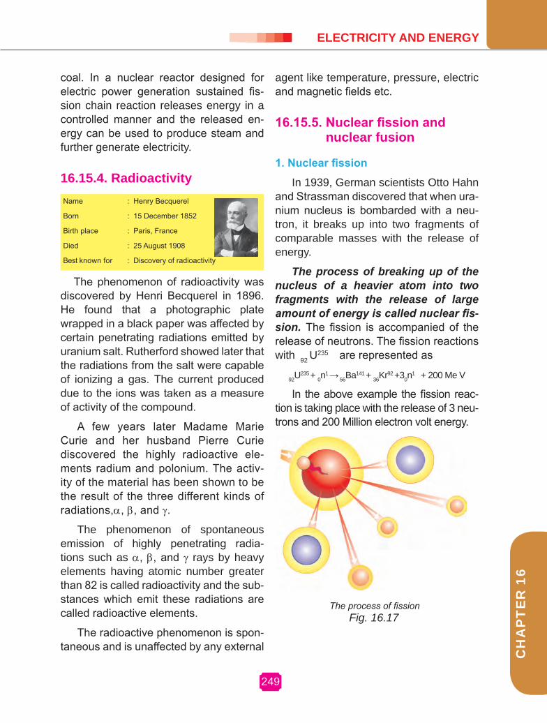
1. Nuclear fission
In 1939, German scientists Otto Hahn and Strassman discovered that when ura-nium nucleus is bombarded with a neu-tron, it breaks up into two fragments of comparable masses with the release of energy.
The process of breaking up of the nucleus of a heavier atom into two fragments with the release of large amount of energy is called nuclear fis-sion. The fission is accompanied of the release of neutrons. The fission reactions with 92 U
235 are represented as
92U235 + 0n
1 → 56Ba141 + 36Kr92 +30n
1 + 200 Me V
In the above example the fission reac-tion is taking place with the release of 3 neu-trons and 200 Million electron volt energy.
Name : Henry Becquerel
Born : 15 December 1852
Birth place : Paris, France
Died : 25 August 1908
Best known for : Discovery of radioactivity
Fig. 16.17The process of fission

250
PH
YS
ICS
2. Nuclear fusion
Nuclear fusion is a process in which two or more lighter nuclei com-bine to form a heavier nucleus. The mass of the product is always less than the sum of the masses of the individual lighter nuclei. According to Einstein’s mass energy relation E = mc2, the dif-ference in mass is converted into en-ergy. The fusion process can be carried out only at a extremely high temperature of the order of 107 K because, only at these very high temperatures the nu-clei are able to overcome their mutual repulsion. Therefore before fusion, the lighter nuclei must have their tempera-ture raised by several million degrees. The nuclear fusion reactions are known as thermo nuclear reactions.
A suitable assembly of neutron and deuteron and triton is arranged at the sight of the explosion of the atom bomb. Favorable temperature initiates the fusion of light nuclei in an uncontrolled manner. This releases enormous amount of heat energy. This is the hydrogen bomb.
The fusion reaction in the hydrogen bomb is 1H2 + 1H3 → 2 He4 + 0n1 + Energy
Example: 16.8
Calculate the energy produced when 1 kg of substance is fully converted into energy.
Solution:
Energy produced, E = mc2
Mass, m = 1 kgVelocity of light, c = 3×10⁸ m s-1
E = 1×(3×108 )2
E = 9 × 10¹⁶ J
16.15.6. Nuclear reactivity AdvantantagesNuclear reactivity is a measure of the de-parture of a reactor from criticality. It is a useful concept to predict how the neutron population of a reactor will change over time.
If a reactor is exactly critical, that is, the neutron production is exactly equal to the neutron destruction, then the reac-tivity is zero. If the reactivity is positive, then the reactor is super critical. If the re-activity is negative, then the reactor is sub critical.
16.15.7. Hazards of nuclear energy
α, β and γ radiations are all ioniz-ing radiations. These radiations cause a change in the structure of molecules in cells, disturbs the normal functioning of the biological system. The extent to which the human organism is damaged depends upon
1. The dose and the rate at which the radiation is given and
2. The part of the body exposed to it. The damage may be either pathological or genetic.
The radiation exposure is meas-ured by the unit called roentgen(R). One roentgen is defined as the quantity of ra-diation which produces 1.6 x 10¹² pairs of ion in 1 gram of air.
Safe limit of receiving the radiation is about 250 milli roentgen per week.
The following precautions are to be taken for those, who are working in radia-tion laboratories.

251
CH
AP
TE
R 9
CH
AP
TE
R 1
6
ELECTrICITY AND ENErgY
(i) Radioactive materials are kept in thick-walled lead container.
(ii) Lead aprons and lead gloves are used while working in hazardous area.
(iii) A small micro-film badge is always worn by the person and it is checked periodically for the safety limit of radiation.
(iv) Nuclear devices can be operated using remote control system.
(v) Clean up contamination in the work area promptly.
16.15.8. SCIENCE TODAY - Energy from seas
1. Tidal energyDue to the gravitational pull of mainly
the moon on the spinning earth, the level of the water in the sea rises and falls. If you live near the sea or ever travel to some place near the sea, try and observe how the sea-level changes during the day. The
ing to the sea. A turbine fixed at the open-ing of the dam converts tidal energy to electricity. Fig. 16.18. As you can guess, the locations where such dams can be built are limited. 2. wave energy
Similarly, the kinetic energy possessed by huge waves near the sea-shore can be trapped in a similar manner that gener-ates electricity. The waves are generated by strong winds blowing across the sea. Wave energy would be a viable proposi-tion only where waves are very strong. A wide variety of devices has been de-veloped to trap wave energy for rotation of turbine and production of electricity. Fig.16.19
Fig. 16.18
Fig. 16.19
Air back in Air out
GeneratorTurbine
WaveDirection
phenomenon is called high and low tides and the difference in sea-levels gives us tidal energy. Tidal energy is harnessed by constructing a dam across a narrow open-
3. Ocean thermal energyThe water at the surface of the sea or
ocean is heated by the sun while the wa-ter in deeper sections is relatively cooled. This difference in temperature is exploited to obtain energy in ocean-thermal-energy conversion plants. These plants can oper-ate if the temperature difference between the water at the surface and water at depths up to 2 kilometers is 293 K (20° C) or more . The warm surface-water is used

252
PH
YS
ICS
to boil a volatile liquid like ammonia. The vapors of liquid then used to run the tur-bine of generator. The cooled water from the depth of the ocean is pumped up and condense vapor again to liquid. Fig.16.20.
The energy potential from the sea (tidal energy, wave energy and ocean thermal energy) is quiet large, but efficient commercial exploitation is difficult.
PArT A1. The potential difference required
to pass a current 0.2 A in a wire of resistance 20 ohm is _________.(100 V, 4 V, 0.01 V, 40 V)
2. Two electric bulbs have resistances in the ratio 1 : 2. If they are joined in series, the energy consumed in these are in the ratio _________.(1 : 2, 2 : 1, 4 : 1, 1 : 1)
3. Kilowatt-hour is the unit of __________.(potential difference, electric power, electric energy, charge)
4. ________ surface absorbs more heat than any other surface under identical conditions. (White, rough, black, yellow)
5. The atomic number of natural radioactive element is _________.(greater than 82, less than 82, not defined, atleast 92)
PArT B1. From the following statements write down
that which does not represent ohm’s law.
Fig. 16.20
Warm sea water
Heat exchanger
(evaporator)
GeneratorAmmonia vapours
Cold sea water
Pump
Liquid ammoniaDischarge
Turbine
Heat exchanger
(condenser)
a) current / potential difference = constant
b) potential difference / current = constant
c) current = resistance x potential difference
2. Fill in the blanks a) Potential difference : voltmeter,
then: current __________. b) power plant : conventional source
of energy then solar energy _____.
3. In the list of sources of energy given below, some of them are wrong. List out the wrong ones. (Wind energy, solar energy, hydro electric power, nuclear energy, tidal energy, wave energy, geo-thermal energy.)
4. Correct the mistakes, i f any, in the fo l lowing statements. a) A good source of energy would be
one which would do a small amount of work per unit volume of mass.
b) Any source of energy we use to do work is consumed and can be used again.
EVALUATION
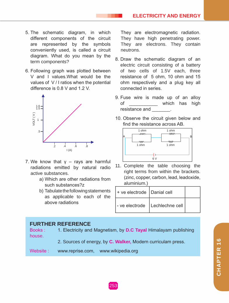
253
CH
AP
TE
R 9
CH
AP
TE
R 1
6
ELECTrICITY AND ENErgY
5. The schematic diagram, in which different components of the circuit are represented by the symbols conveniently used, is called a circuit diagram. What do you mean by the term components?
6. Following graph was plotted between V and I values.What would be the values of V / I ratios when the potential difference is 0.8 V and 1.2 V.
7. We know that γ – rays are harmful radiations emitted by natural radio active substances.
a) Which are other radiations from such substances?z
b) Tabulate the following statements as applicable to each of the above radiations
.2 .4 .6 .8I (A)
.5
1
1.51.6
VO
LT(V
)
+ ve electrode Danial cell
- ve electrode Lechlechne cell
They are electromagnetic radiation.They have high penetrating power.They are electrons. They contain neutrons.
8. Draw the schematic diagram of an electric circuit consisting of a battery of two cells of 1.5V each, three resistance of 5 ohm, 10 ohm and 15 ohm respectively and a plug key all connected in series.
9. Fuse wire is made up of an alloy of ___________ which has high resistance and _______.
10. Observe the circuit given below and find the resistance across AB.
A B
6 V
1 ohm
1 ohm 1 ohm
1 ohm
11. Complete the table choosing the right terms from within the brackets. (zinc, copper, carbon, lead, leadoxide, aluminium.)
FUrTHEr rEFErENCEBooks : 1. Electricity and Magnetism, by D.C Tayal Himalayam publishing house. 2. Sources of energy, by C. walker, Modern curriculam press.
Website : www.reprise.com, www.wikipedia.org
Chapter 17
MAgNETIC EFFECT OF ELECTrIC CUrrENT AND LIgHT

255
CH
AP
TE
R 1
7
17. MAGNETIC EFFECT OF ELECTRIC CURRENT AND LIGHT
17.1. MAgNETIC FIELD ANDMAgNETIC LINES OF FOrCE
We are familiar with the fact that a compass needle gets deflected when brought near a bar magnet. Why does a compass needle get deflected?
Name : OerstedBorn : 14 August 1777Birth place : Langeland DenmarkDied : 9 March 1851Best known for : The study of electromagnetism
ACTIvITY 17.1
• Fix a sheet of white paper on a drawing board using some adhesive material.
• Place a bar magnet in the centre of it.
• Sprinkle some iron fillings uniformly around the bar magnet (Fig 17.1).
• A salt-Sprinkler may be used for this purpose.
• Now tap the board gently. • What do you observe?
N S
The iron fillings arrange themselves in a pattern as shown in Fig. 17.1. Why do the iron fillings arrange in such a pattern? What does this pattern demonstrate? The magnet exerts its influence in the region surrounding it. Therefore the iron fillings experience a force. The force thus exerted makes iron fillings to arrange in a pattern. The region surrounding the magnet, in which the force of the magnet can be detected, is said to have a magnetic field. The lines along which the iron fillings align themselves represent magnetic lines of force.
Fig. 17.1
255
MAGNETIC EFFECT OF ELECTRIC CURRENT AND LIGHT

256
PH
YS
ICS
Fig 17.2
NS
Fig 17.3
Magnetic field is a quantity that has both magnitude and direction. The direction of the magnetic field is taken to be the direction in which a north pole of the compass needle moves inside it. Therefore it is taken by convention that the field lines emerge from the north pole and merge at the south pole as shown in Fig.17.3. Inside the magnet, the direction of field lines is from its south pole to its north pole. Thus the magnetic field lines are closed curves. No two field-lines are found to cross each other.
17.2. MAgNETIC FIELD DUE TO CUrrENT CArrYINg CONDUCTOr
In the activity 17.3 we have seen that electric current through a metallic conductor
• Take a small compass and a bar magnet.
• Place the magnet on a sheet of white paper fixed on a drawing board, using some adhesive material.
• Mark the boundary of the magnet.
• Place the compass near the north pole of the magnet. How does it behave? The south pole of the needle points towards the north pole of the magnet. The north pole of the compass is directed away from the north pole of the magnet.
• Mark the position of two ends of the needle.
• Now move the needle to a new position such that its south occupies the position previously occupied by its north pole.
• In this way, proceed step by step till you reach the south pole of the magnet as shown
• Join the points marked on the paper by a smooth curve. This curve represents a field line.
• Repeat the above procedure and draw as many lines as you can. You will get a pattern shown in Fig.17.2.These lines represent the magnetic field around the magnet. These are known as magnetic field lines.
• Observe the deflection of the compass needle as you move it along the field line. The deflection increases as the needle is moved towards the pole.
ACTIvITY 17.2
S NN
SS
N

CH
AP
TE
R 1
7
257
MAgNETIC EFFECT OF ELECTrIC CUrrENT AND LIgHT
produces a magnetic field around it. If the current flows in one direction (from X to Y), the north pole of the compass needle would move towards the east. If the current flows in opposite direction (from Y to X), you will see that the needle moves in opposite direction, that is towards the west. It means that the direction of magnetic field
produced by the electric current depends upon the direction of flow of current.
17.2.1. Magnetic field due to current carrying straight conductor
What determines the pattern of the magnetic field generated by current through a conductor? Does the pattern depend on the shape of the conductor? We shall investigate this with an activity.
• Take a battery (12 V), a variable resistance (rheostat), an ammeter (0-5A), a plug key, and a long straight thick copper wire.
• Insert the thick wire through the centre, normal to the plane of a rectangular cardboard. Take care that the cardboard is fixed and does not slide up or down.
• Connect the copper wire vertically between the points X and Y, as shown in Fig 17.5(a), in series with the battery, a plug key, ammeter and a rheostat.
• Sprinkle some iron fillings uniformly on the cardboard. (you may use a salt sprinkler for this purpose).
• Keep the variable of the rheostat at a fixed position and note the current through the ammeter.
• Close the key so that the current flows through the wire. Ensure that the copper wire placed between the points X and Y remains vertically straight.
ACTIvITY 17.4
• Take a straight thick copper wire and place it between the points X and Y in an electric circuit, as shown in Fig..17.4. The wire XY is kept perpendicular to the plane of the paper.
• Horizontally place a small compass near this copper wire. See the position of its needle.
• Pass the current through the circuit by inserting the key into the plug.
• Observe the change in the position of the compass needle and the direction of deflection.
• Replace the cell connection in the circuit so that the direction of the current in the copper wire changes.
• Observe the change in the direction of deflection of the needle.
ACTIvITY 17.3
Fig 17.4
257

258
What happens to the deflection of the compass needle placed at a given point if the current in the copper wire is changed? We find that the deflection in the needle also changes. In fact, if the current is increased, the deflection also increases. It indicates that the magnitude of the magnetic field produced at a given point increases as the current through the wire, increases.
What happens to the deflection of the needle if the compass is moved from the copper wire but the current through the wire remains the same? To see this, now place the compass at a farther point from the conducting wire. What change do you observe? We see that the deflection in the needle decreases. Thus the magnetic field produced by the given current in the conductor decreases as the distance from it increases. From Fig.17.5 (b), it can be noticed that the concentric circles representing the magnetic field around a current-carrying straight wire become larger and larger as we move away from it.
17.2.2. Magnetic field due to current carrying circular loop
We have so far observed the pattern of the magnetic field lines produced around a current-carrying straight wire. Suppose this straight wire is bent in the form of a circular loop and current is passed through it, how would the magnetic field lines look like?
We know that the magnetic field produced by a current- carrying straight wire depends inversely on the distance
• Gently tap the cardboard a few times. Observe the pattern of the iron fillings. You would find that the iron fillings align themselves showing a pattern of concentric circles around the copper wire, Fig 17.5(b).
• What do these concentric circles represent? They represent the magnetic field lines.
• How can the direction of the magnetic field be found? Place a compass at a point (say P) over a circle. Observe the direction of the needle. The direction of the north pole of the compass needle would give the direction of the field lines produced by the electric current through the straight wire at point P. Show the direction by an arrow.
• Does the direction of magnetic field lines get reversed if the direction of current through the straight copper wire is reversed? Check it.
Variable resistence
Fig.17.5PH
YS
ICS

CH
AP
TE
R 1
7
MAgNETIC EFFECT OF ELECTrIC CUrrENT AND LIgHT
from it. Similarly at every point of a current-carrying circular loop, the concentric circles representing the magnetic field around it becomes larger and larger as we move away from the wire (Fig. 7.7).
By the time we reach the centre of the circular loop, the arcs of these big circles would appear as straight lines. Every point on the wire carrying current would give rise to the magnetic field appearing as straight lines at the centre of the loop.
Fig.17.7
We know that the magnetic field produced by a current- carrying conductor at a given point, depends directly on the current passing through it. Therefore, if there is a circular coil having n turns, the field produced is n times as large as produced by a single turn. This is because the current in each circular turn has the same direction, and the field due to each turn then just adds up.
17.3. FOrCE ON A CUrrENT CArrYINg CONDUCTOr IN A MAgNETIC FIELD
We know that an electric current flowing through a conductor produces a magnetic field. The field so produced exerts a force on a magnet placed in the vicinity of a conductor. French scientist Andre Marie Ampere suggested that the magnet must also exert an equal and opposite force on the current carrying conductor. The force due to a current carrying conductor can be demonstrated through the following activity.
N S
• Take a rectangular cardboard having two holes. Insert a circular coil having large number of turns through them, normal to the plane of the cardboard.
• Connect the ends of the coil in series with a battery, a key and rheostat, as shown in Fig.17.6.
• Sprinkle iron fillings uniformly on the cardboard.
• Plug the key.
• Tap the cardboard gently a few times. Note the pattern of the iron fillings that emerges on the cardboard.
ACTIvITY 17.5
_ +
A
B
K
Fig.17.6
1572597

260
PH
YS
ICS
The displacement of the rod in the above activity suggests that a force is exerted on the current- carrying aluminium rod when it is placed on a magnetic field. It also suggests that the direction of force is also reversed when the direction of current through the conductor is reversed. Now change the direction of field to vertically downwards by interchanging the two poles of the magnet. It is once again observed that the direction of force acting on the current-carrying rod gets reversed. It shows that the direction of force on the conductor depends upon the direction of current and the direction of magnetic field. Experiments have shown that the displacement of the rod is largest when the direction of current is at right angles to the direction of magnetic field.
17.3.1. Fleming left hand ruleWe considered that the direction of
the current and that of the magnetic field perpendicular to each other and found that the force is perpendicular to both of them. The three directions can be illustrated through a simple rule, called Fleming’s left hand rule.(Fig.17.9).
Field
Field
Thumb - Motion Current
Current
Force
Fig. 17.9
Stretch the thumb, fore finger and middle finger of your left hand such
• Take a small aluminium rod AB of about 5 cm. using two connecting wires suspend it horizontally from a stand as shown in Fig. 17.8.
• Place a horse-shoe magnet in such a way that the rod lies between two poles with the magnetic field directed upwards. For this put the North Pole of the magnet vertically below and South Pole vertically above the aluminium rod.
• Connect the aluminium rod in series with a battery, a key and a rheostat.
• Now pass a current through the aluminium rod from end B to A.
• What do you observe? It is observed that the rod is displaced towards the left. You will notice that the rod gets displaced.
• Reverse the direction of current flowing through the rod and observe the direction of its displacement. It is now towards the right.
• Why does the rod get displaced?
ACTIvITY 17.6
Fig. 17.8

CH
AP
TE
R 1
7
261
MAgNETIC EFFECT OF ELECTrIC CUrrENT AND LIgHT
that they are mutually perpendicular. If the forefinger points in the direction of magnetic field and the middle finger points in the direction of current, then the thumb will point in the direction of motion or the force acting on the conductor.
17.4. ELECTrIC MOTOrAn electric motor is a rotating device
that converts electrical energy in to mechanical energy. Do you know how an electric motor works?
An electric motor, as shown in Fig. 17.10, consists of a rectangular coil ABCD of insulated copper wire. The coil is placed between two poles of a magnetic field such that the arm AB and CD are perpendicular to the direction of magnetic field. The ends of the coil are connected to the two halves S1 and S2 of a split ring. The inner side of these halves insulated and attached to an axle. The external conducting edges of S1 and S2 touch two conducting stationary brushes B1 and B2, respectively.
( )
B1
S1
B2
B2
K Bt
A D
B C
Current in the coil ABCD enters from the source battery through conducting brush B1 and flows back to the battery through brush B2. Notice that the current in arm AB of the coil flows from A to B. In arm CD it flows from C to D, that is, opposite to the direction of current through arm AB. On applying Fleming’s left hand rule for the direction of force on a current-carrying conductor in a magnetic field. We find that the force acting on arm AB pushes it downwards while the force acting on arm CD pushes it upwards. Thus the coil and the axle, mounted free to turn about an axis, rotate anti-clockwise. At half rotation S2 makes contact with the brush B1 and S2 with brush B2. Therefore the current in the coil gets reversed and flows along the path DCBA. A device that reverses the direction of flow of current through a circuit is called a commutator. In electric motors, the split ring acts as a commutator. The reversal of current also reverses the direction of force acting on the two arms AB and CD. Thus the arm AB of the coil that was earlier pushed down is now pushed up and the arm CD previously pushed up is now pushed down. Therefore the coil and the axle rotate half a turn more in the same direction. The reversing of the current is repeated at each half rotation, giving rise to a continuous rotation of the coil and to the axle.
The commercial motors use (i) an electro magnet in place of permanent magnet; (ii) large number of turns of the conducting wire in the current-carrying coil, and (iii) a soft iron core on which the coil is wound . The soft iron core, on which the coil is wound, plus the coils, is called an armature. This enhances the power of the motor. Fig. 17.9
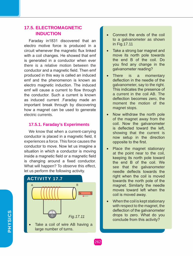
262
PH
YS
ICS
17.5. ELECTrOMAgNETIC INDUCTION
Faraday in1831 discovered that an electro motive force is produced in a circuit whenever the magnetic flux linked with a coil changes. He showed that emf is generated in a conductor when ever there is a relative motion between the conductor and a magnetic field. Then emf produced in this way is called an induced emf and the phenomenon is known as electro magnetic induction. The induced emf will cause a current to flow through the conductor. Such a current is known as induced current .Faraday made an important break through by discovering how a magnet can be used to generate electric currents.
17.5.1. Faraday’s ExperimentsWe know that when a current-carrying
conductor is placed in a magnetic field, it experiences a force. This force causes the conductor to move. Now let us imagine a situation in which a conductor is moving inside a magnetic field or a magnetic field is changing around a fixed conductor. What will happen? To observe this effect, let us perform the following activity.
ACTIvITY 17.7
N S
G
A B
Fig.17.11
• Take a coil of wire AB having a large number of turns.
• Connect the ends of the coil to a galvanometer as shown in Fig.17.11
• Take a strong bar magnet and move its north pole towards the end B of the coil. Do you find any change in the galvanometer reading?
• There is a momentary deflection in the needle of the galvanometer, say to the right. This indicates the presence of a current in the coil AB. The deflection becomes zero, the moment the motion of the magnet stops.
• Now withdraw the north pole of the magnet away from the coil. Now the galvanometer is deflected toward the left, showing that the current is now setup in the direction opposite to the first.
• Place the magnet stationary at the point near to the coil, keeping its north pole toward the end B of the coil. We see that the galvanometer needle deflects towards the right when the coil is moved towards the north pole of the magnet. Similarly the needle moves toward left when the coil is moved away.
• When the coil is kept stationary with respect to the magnet, the deflection of the galvanometer drops to zero. What do you conclude from this activity?
PH
YS
ICS

CH
AP
TE
R 1
7
MAgNETIC EFFECT OF ELECTrIC CUrrENT AND LIgHT
You can also check that if you have moved South Pole of the magnet towards the end B of the coil, the deflections in the galvanometer would just be opposite to the previous case. When the coil and the magnet are both stationary, there is no deflection in the galvanometer. It is thus clear that motion of a magnet with respect to the coil produces an induced electromotive force, which sets up an induced electric current in the circuit.
Let us now perform a different activity in which the moving magnet is replaced by a current-carrying coil and the current in the coil can be varied. In this activity we observe that as soon
as the current in coil-1 reaches either a steady value or zero, the galvanometer in coil-2 shows no deflection. From these observations we conclude that a potential difference is induced in coil-2 when ever the current through the coil-1 is changing. Coil-1 is called the primary coil and coil-2 is called the secondary coil. As the current in the first coil changes, the magnetic field associated with it also changes. Thus the magnetic field lines around the secondary coil also change. Hence the change in magnetic field lines associated with the secondary coil is the cause of induced electric current in it. The direction of the induced current can be found using Fleming’s right hand rule.
Stretch the thumb, forefinger and middle finger of right hand so that they are perpendicular to each other. If the forefinger indicates the direction of the magnetic field and the thumb shows the direction of motion of conductor, then the middle finger will show the direction of induced current.
• Two different coils of copper wire having large number of turns (say 50 and 100 turns respectively). Insert them over a non conducting cylindrical roll as shown in Fig.17.12.
• Connect the coil -1 having large number of turns, in series with a battery and a plug key. Also connect the other coil -2 with a galvanameter assam.
• Plug in the key. Observe the galvanameter. Is there a deflection in its needle?. You will observe that the needle of the galvanameter instantly jumps to one side and just as quickly returns to zero, indicating a momentary current in coil -2.
• Disconnect coil-1 from the battery. You will observe that the needle momentarily moves, but to the opposit side. It means that,
ACTIvITY 17.8
Now the current flows in the opposite direction in coil -2.
Fig. 17.12
Coil -1 Coil -2
1572637

264
PH
YS
ICS
17.6. ELECTrIC gENErATOrThe phenomenon of electro magnetic
induction is employed to produce large currents for use in homes and industry. In an electric generator, mechanical energy is used to rotate a conductor in a magnetic field to produce electricity.
An electric generator, as shown in Fig.17.13a, consists of rotating rectangular coil ABCD placed between the two poles of a permanent magnet. The two ends of this coil are connected to the two rings S1 and S2. The inner sides of these rings are made insulated. The two conducting stationary brushes B1 and B2 are kept pressed separately on the rings S1 and S2 respectively. The two rings S1 and S2 are internally attached to an axle. The axle may be mechanically rotated from outside to rotate the coil inside the magnetic field. Outer ends of the two brushes are connected to the external circuit.
When the axle attached to the two rings is rotated such that the arm AB moves up, the arm CD moves down in the magnetic field produced by the permanent magnet. Let us say the coil ABCD is rotated clockwise. By applying Fleming’s right-hand rule the induced currents are setup in these arms along the directions AB and CD. Thus an induced current flows in the direction ABCD. If there are large numbers of turns in the coil, the current generated in each turn adds up to give a large current through the coil. This means that the current in the external circuit flows from B2 to B1.
After half a rotation, arm CD starts moving up and AB moving down. As
a result, the directions of the induced currents in both the arms change, giving rise to the net induced current in the direction DCBA. The current in the external circuit now flows from B1 to B2. Thus after every half rotation the polarity of the current in the respective arms changes. Such a current which changes direction after equal intervals of time, is called an alternating current (AC). This device is called an AC generator.
A.C generator
D.C Generator
Fig 17.13b
a
A D
B C
N S
RB1
B2
S2
S1
PH
YS
ICS

CH
AP
TE
R 1
7
26
MAgNETIC EFFECT OF ELECTrIC CUrrENT AND LIgHT
To get a direct current (DC), a split-ring type commutator must be used with this arrangement, Fig.17.13b, one brush is at all times in contact with the arm moving up in the field, while the other is in contact with the arm moving down. Thus a unidirectional current is produced. The generator is thus called a DC generator.
An important advantage of AC over DC is that electric power can be transmitted over long distances without much loss of energy.
17.7. LIgHTWe see a variety of objects in the world
around us. However we are unable to see anything in a dark room. On lighting up the room things becomes visible. What makes things visible? During the day the sunlight helps us to see objects. An object reflects light that falls on it. This reflected light when received by our eyes, enables us to see things.
There are a number of common wonderful phenomena associated with light. In this chapter, we shall study the phenomena of reflection and refraction of light using the straight-line propagation of light.
Reflection of lightA highly polished surface, such as a
mirror, reflects most of the light falling on it. You are already familiar with the laws of reflection of light. Let us recall these laws.
(i) The angle of incidence is equal to the angle of reflection, and
(ii) The incident ray, the normal to the mirror at the point of incidence and the reflected ray, all lie in the same plane.
These laws of reflection are applicable to all types of reflecting surfaces including spherical surfaces.
Spherical mirrorsACTIvITY 17.9
• Take a perfect hemispherical spoon. Try to view your face in its curved surface.
• Do you get the image? Is it larger or smaller?
• Move the spoon slowly away from your face. Observe the image. How does it change?
• Reverse the spoon and repeat the activity. How does the image look like now?
• Compare the characteristics of the images on the two surfaces.
The curved surface of a shining spoon could be considered as a curved mirror. The most commonly used type of curved mirror is the spherical mirror. The reflecting surface of a spherical mirror may be curved inwards or outwards. A spherical mirror whose reflecting surface is curved inwards is called a concave mirror. A spherical mirror whose reflecting surface is curved outwards is called a convex mirror. The schematic representation of these mirrors is shown in Fig. 17.14.
Fig 17.14
(a) concave mirror (b) convex mirror
157265

266
PH
YS
ICS
You may now understand that the surface of the spoon curved inwards can be approximated to a concave mirror and the surface of the spoon bulged outwards can be approximated to a convex mirror.
Before we move further on spherical mirrors, we need to recognise and understand the meaning of a few terms. These terms are commonly used in discussions about spherical mirrors.
The centre of the reflecting surface of a spherical mirror is a point, called the pole. It is represented by the letter P.
The reflecting surface of a spherical mirror forms a part of a sphere. This sphere has a centre. This point is called the centre of curvature of the spherical mirror. It is represented by the letter C.
The radius of the sphere of which the reflecting surface of a spherical mirror forms a part, is called the radius of curvature of the mirror. It is represented by the letter R.
Imagine a straight line passing through the pole and the centre of curvature of a spherical mirror. This line is called the principle axis.
Let us understand important terms related to mirrors, through above activity.
The paper at first begins to burn producing smoke. It may even catch fire. Why does it burn? The light from the sun is converged at a point, as a sharp, bright spot by the mirror. In fact, this spot of light is the image of the sun on the sheet of paper. This point is the focus of the concave mirror. The heat produced due to the concentration of the sunlight ignites the paper. The distance of the image from the position of the mirror gives the approximate focal length of the mirror. Observe Fig.17.15(a) closely
Fig. 17.15
A number of rays parallel to the principal axis are falling on a concave mirror. Observe the reflected rays. They are all meeting at a point on the principal axis of the mirror. This point is called the principal focus of the concave mirror. Similarly
A
B
Ir
. D
P
N
M
C F
N
M
D
CF
EP
G
A
B
At Infinity
At Infinity
ACTIvITY 17.10 • Hold a concave mirror in your hand
and direct its reflecting surface towards the sun.
• Direct the light reflected by the mirror on to a sheet of paper held close to the mirror.
• Move the sheet of paper back and forth gradually until you find on the paper sheet a bright, sharp spot of light.
• Hold the mirror and the paper in the same position for a few minutes. What do you observe? Why?
(a)
(b)
PH
YS
ICS

CH
AP
TE
R 1
7
MAgNETIC EFFECT OF ELECTrIC CUrrENT AND LIgHT
observe Fig. 17.15(b). How are the rays parallel to the principal axis reflected by a convex mirror? The reflected rays appear to come from a point on the principal axis. This point is called the principal focus of the convex mirror. The principal focus is represented by the letter F.
The distance between the pole and the principal focus of a spherical mirror is called the focal length. It is represented by the letter f.
The diameter of the reflecting surface of spherical mirror is called its aperture. In fig 17.15, distance MN represents the aperture. In our discussion we shall consider only such spherical mirrors whose aperture is much smaller than its radius of curvature.
Is there any relationship between the radius of curvature R, and focal length f, of a spherical mirror? For spherical mirrors of small apertures the radius of curvature is found to be equal to twice the focal length. We put this as r = 2f.
17.7.1 Reflection of light by spherical mirror
The reflection of light by a spherical mirror takes place according to certain definite rules as follows.
(i) A ray parallel to the principal axis, after reflection, will pass through principal focus in case of a concave mirror or appear to diverge from the principal focus in case of a convex mirror. This is illustrated in Fig. 17.16(a) and (b).
Fig. 17.16
(ii) A ray passing through the principal focus of a concave mirror or a ray directed towards the principal focus of a convex mirror, after reflection, will emerge parallel to the principal axis. This is illustrated in Fig.17.17 (a) and (b).
Fig. 17.17
I.r
C FP
F CP
rI.
(a)
I.r
C FP
F CP
rI.
(b)
P F C
rI.
CPF
r I.
(a)
157267

268
PH
YS
ICS
(iii) A ray passing through the centre of curvature of a concave mirror or directed in the direction of the centre of curvature of a convex mirror, after reflection, is reflected back along the same path. This is illustrated in Fig.17.18 (a) and (b).
Fig 17.18
Image formation by concave mirrorHow about the images formed by
spherical mirrors? How can we locate the image formed by a concave mirror for different positions of the object? Are the images real or virtual? Are the images enlarged, diminished or have the same size?
The nature, position and size of the image formed by a concave mirror depend on the position of the object in relation to point P, F and C. The image formed is real for some positions of the object. It is found to be a virtual image for a certain other position. The image is either magnified, reduced or has the same size, depending on the position of the object.
We can study the formation of image by spherical mirrors by drawing ray diagrams. To construct the ray diagrams, it is more convenient to consider only two rays. These rays are so chosen that it is easy to know their directions after reflection from the mirror. You may take any two of the rays mentioned in the previous section for locating the image. The intersections of the two reflected rays give the position of image of the point object. This is illustrated in the Fig.17.19.
Uses of concave mirrorConcave mirrors are commonly used in
torches, search-lights and vehicles head lights to get powerful parallel beams of light. They are used as shaving mirrors to see a lager image of the face. The dentists use concave mirrors to see large images of the teeth of patients. Large concave mirrors are used to concentrate sun light to produce heat in solar furnaces.
P F C
rI.
CPF
r I.
(b)
C FP
P F C
(a)
C FP
P F C
(b)
PH
YS
ICS

CH
AP
TE
R 1
7
MAgNETIC EFFECT OF ELECTrIC CUrrENT AND LIgHT
Fig 17.19
A
B
C FP
Dr
I.
A
C F
M
D
P
E
N
A
CABF
M
DE
P
N
A M
P
N
A1
B1
B C
D
F
B1 CA
ME
DPFB
A1 N
CF B
AM E
A1
B1P
N
rI.
B
B
(a)(b)
(c)(d)
(e) (f)
At Infinity
At Infinity
Position of the Object
Position of the image
relative size of the image
Nature of the image
At infinity At focus F2 Highly dimin-ished, point-sized
Real and inverted
Beyond 2F1 Between F2 and 2F2 Diminished Real and inverted
At 2F1 At 2F2 Same size Real and inverted
Between F1 & 2F1 Beyond 2F2 Enlarged Real and inverted
At focus F1 At infinity Infinitely large or highly enlarged
Real and inverted
Between focus F1 and optical centre O
On same side of the lens as the object
Enlarged Virtual and erect
A summary of these observations is given in Table: 17.1.
Table 17.1
157269
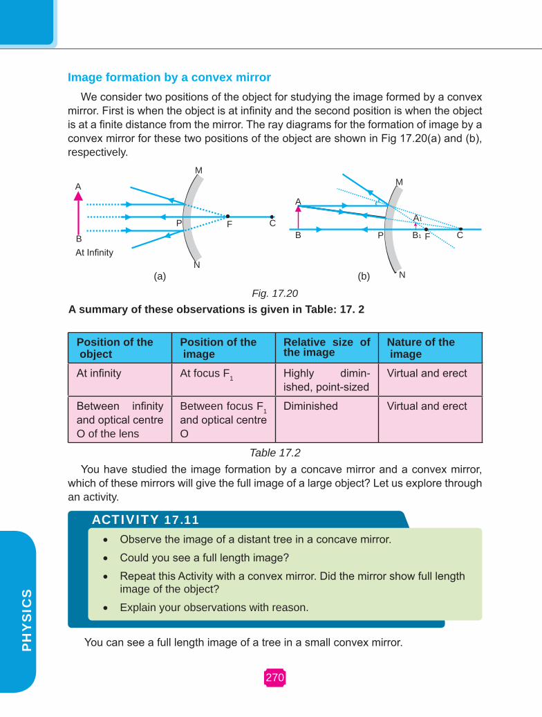
270
PH
YS
ICS
Image formation by a convex mirrorWe consider two positions of the object for studying the image formed by a convex
mirror. First is when the object is at infinity and the second position is when the object is at a finite distance from the mirror. The ray diagrams for the formation of image by a convex mirror for these two positions of the object are shown in Fig 17.20(a) and (b), respectively.
You have studied the image formation by a concave mirror and a convex mirror, which of these mirrors will give the full image of a large object? Let us explore through an activity.
Position of the object
Position of the image
relative size of the image
Nature of the image
At infinity At focus F1 Highly dimin-ished, point-sized
Virtual and erect
Between infinity and optical centre O of the lens
Between focus F1 and optical centre O
Diminished Virtual and erect
A summary of these observations is given in Table: 17. 2
Table 17.2
Fig. 17.20
A
B
M
P F C
N
A
B
M
A1
B1 F C
N
P
At Infinity
(b)(a)
ACTIvITY 17.11 • Observe the image of a distant tree in a concave mirror.
• Could you see a full length image?
• Repeat this Activity with a convex mirror. Did the mirror show full length image of the object?
• Explain your observations with reason.
You can see a full length image of a tree in a small convex mirror.PH
YS
ICS

CH
AP
TE
R 1
7
MAgNETIC EFFECT OF ELECTrIC CUrrENT AND LIgHT
Uses of convex mirrorsConvex mirrors are commonly used
as rear-view mirrors in vehicles. These mirrors are fitted on the sides of the vehicle, enabling the driver to see traffic behind him/her to facilitate safe driving. Convex mirrors are preferred because they always give an erect image. Also they have a wider field of view as they are curved outwards.
Sign convention for reflection by spherical mirrors
While dealing with the reflection of light by spherical mirrors, we shall follow a set of sign conventions called the New Cartesian Sign Convention. In this convention, the pole (P) of the mirror is taken as the origin. The principal axis of the mirror is taken as the X axis (X′X) of the coordinate system. The conventions are as follows.
(i) The object is always placed to the left of the mirror.
(ii) All distances parallel to the principal axis are measured from the pole of the mirror.
(iii) All the distances measured to the right of the origin (along +X-axis) are taken as positive while those measured to the left of the origin (along -X-axis) are taken as negative
(iv) Distances measured perpendicular to and above the principal axis (along +Y-axis) are taken as positive.
(v) Distances measured perpendicular to and below the principal axis (along -Y-axis) are taken as negative.
The New Cartesian Sign Convention described above is illustrated in Fig. 17.21.
Fig. 17.21
These sign conventions are applied to obtain the mirror formula
Mirror formulaIn a spherical mirror, the distance of
the object from its pole is called the object distance (u). The distance of the image from the pole of the mirror is called the image distance (v). You already know that the distance of the principal focus from the pole is called the focal length (f). There is a relationship between these three quantities given by the mirror formula which is expressed as
1/v + 1/u = 1/f
This formula is valid in all situations for all spherical mirrors for all positions of the object. You must use the New Cartesian Sign convention while substituting numerical values for u, v, f, and R in the mirror formula for solving problems.
Example: 17.1
A convex mirror used for rear-view on an automobile has a radius of curvature of 3 m. If a bus is located at 5 m from this
X X
M
P
N
B B1
A1
A
Object on the leftDirection of
Distance towards Distance towards
Incident Light
the left -ve the right +ve
Height Upwards
+ve
Height downwards
-ve
Mirror
1572717
272
PH
YS
ICS
mirror, find the position and nature of the image.
Solution:
Radius of curvature, R = +3.00 m
Object distance u = - 5.00 m
Image distance v = ?
Focal length ,
f = R/2 = + 3.00 m/2 = 1.5 m
We know, 1 1 1
— + — = — v u f
or, 1 1 1
— = — – — v f u
1 1 1 1 = — – —— = — + —— 1.5 -5.00 1.5 5.00
5.00 +1.50 6.50 = = 7.50 7.50
7.50 V = = 1.15 m 6.50
The image is 1.15 m at the back of the mirror. The image is virtual.
17.7.2. refraction of lightLight seems to travel along straight-
line paths in a transparent medium. What happens when light enters from one transparent medium to another? Does it still move along a straight-line path or change its direction? We shall recall some of our day-to-day experiences.
You might have observed that the bottom of a tank or a pond containing
water appears to be raised. Similarly, when a thick glass slab is placed over some printed matter, the letters appear raised when viewed through the glass slab. Why does it happen? Have you seen a pencil partially immersed in water in a glass tumbler? It appears to be displaced at the interface of air and water. You might have observed that a lemon kept in water in a glass tumbler appears to be bigger than its actual size, when viewed from the sides. How can you account such experiences?
Let us consider the case of the apparent displacement of the pencil, partly immersed in water. The light reaching you from the portion of the pencil inside water seems to come from a different direction, compared to the part above water. This makes the pencil appear to be displaced at the interface. For similar reasons, the letters appear to be raised, when seen through a glass slab placed over it.
Does a pencil appear to be displaced to the same extent, if instead of water, we use liquids like kerosene or turpentine? Will the letters appear to rise to the same height if we replace a glass slab with a transparent plastic slab? You will find that the extent of the effect is different for different pair of media. These observations indicate that light does not travel in the same direction in all media. It appears that when traveling obliquely from one medium to another, the direction of propagation of light in the second medium changes. This phenomenon is known as refraction of light. Let us understand this phenomenon further by doing an activity.
PH
YS
ICS

CH
AP
TE
R 1
7
MAgNETIC EFFECT OF ELECTrIC CUrrENT AND LIgHT
The apparent position of the coin as seen through water differ from its actual position .
Laws of refraction
Refraction of light is due to change in the speed of light as it enters from one transparent medium to another. Experiments show that refraction of light occurs according to certain laws. The following are the laws of refraction of light.
(i) The incident ray, the refracted ray and the normal to the interface of two transparent media at the point of incidence, all lie in the same plane.
(ii) The ratio of sine of angle of incidence to the sine of angle of refraction is a constant, for the light of a given colour and for the given pair of media. This law is also known as Snell’s law of refraction. If i is the angle of incidence and r is the angle of refraction, then,
Sin i /sin r = constant
This constant value is called the refractive index of the second medium with respect to the first.
17.7.3 refractive index We know that a ray of light travels
obliquely from one transparent medium into another will change its direction in the second medium. The extent of the change in direction that takes place in a given pair of media is expressed in terms of the refractive index of the second medium with respect to the first medium.
The refractive index can be linked to the relative speed of propagation of light in different media. Light propagates with different speeds in different media. It travels the fastest in vacuum with the highest speed of 3 × 10⁸ m s-1. Its speed reduces considerably in glass.
Consider a ray of light traveling from medium 1 into medium 2 as in Fig.17.22.
ACTIvITY 17.12
• Place a coin at the bottom of a bucket filled with water.
• With your eye to a side above water, try to pick up the coin in one go. Did you succeed in picking up the coin?
• Repeat the Activity. Why did you not succeed in doing it in one go?
• Ask your friends to do this. Compare your experience with theirs.
AN
N
B
Medium 2( Glass)
Medium 1( Air)
I.
r
Fig. 17.22
The refractive index of the second medium with respect to the first
µ = Sin i /sin r
Speed of light in airµ = –––––––––––––––––––––––––
Speed of light in medium
Let i,r be the angle of incidence and angle of refraction.
273

274
PH
YS
ICS
17.7.4 refraction by sphericallensesSpherical lenses
You might have seen people using spectacles for reading. The watchmakers use a small magnifying glass to see tiny parts. Have you ever touched the surface of a magnifying glass with your hand? Is it plane surface or curved? Is it thicker in the middle or at the edges? The glasses used in spectacles and that by watchmaker are examples of lenses. What is a lens? How does it bend light rays? Let us discuss in this section.
A transparent material bound by two surfaces, of which one or both surfaces are spherical, forms a lens. This means that a lens is bound by at least one spherical surface. In such spherical lenses, the other surface would be plane. A lens may have two spherical surfaces, bulging outwards. Such a lens is called a double convex lens. It is simply called a convex lens. It is thicker at the middle as compared to the edges. Convex lens converges light rays. Hence it is called converging lens. Similarly, a double concave lens is bounded by two spherical surfaces, curved inwards. It is thicker at the edges than at the middle. Such lenses diverge light rays and are called diverging lenses. A double concave lens is simply called a concave lens.
Let us understand the meaning of a few terms which are commonly used in discussions about spherical lenses. A lens has two spherical surfaces. Each of these surfaces forms a part of a sphere. The centers of these spheres are called centres of curvature of the lens. The
centre of curvature of a lens is usually represented by the letter C. Since there are two centre’s of curvature, we may represent them as C1 and C2.
An imaginary straight line passing through the two centres of the curvature of a lens is called its principal axis.
The central point of a lens is called its optical centre. It is represented by the letter O. A ray of light through the optical centre of a lens passes without suffering any deviation.
The effective diameter of the circular outline of a spherical lens is called its aperture. Lenses whose aperture is much less than its radius of curvature are called thin lenses with small aperture. What happens when parallel rays of light are incident on a lens?
The light from the sun constitutes parallel rays. These rays were converged by the lens as a sharp bright spot. This is the real image of the sun. The
ACTIvITY 17.13
• CAUTION: Do not look at the sun directly or through a lens while doing this Activity or otherwise. You may damage your eyes if you do so.
• Hold a convex lens in your hand. Direct it towards the sun.
• Focus the light from the sun on a sheet of paper. Obtain a sharp bright image of the sun.
• Hold the paper and the lens in the same position for a while. Keep observing the paper. What happened? Why?
PH
YS
ICS

CH
AP
TE
R 1
7
MAgNETIC EFFECT OF ELECTrIC CUrrENT AND LIgHT
concentration of the sun light at this spot generated heat. This caused the paper to burn.
Observe Fig.17.23(a) carefully.
Fig.17.23(a)
Several rays of light parallel to the principal axis are falling on a convex lens. These rays after refraction from the lens are converging to a point on the principal axis. This point is called the principal focus of the lens.
Observe Fig. 17.23(b) carefully,
Fig.17.23(b)
Several rays of light parallel to the principal axis are falling on a concave lens. These rays after refraction from the lens, are appearing to diverge from a point on the principal axis. This point is called the principal focus of the concave lens.
If you pass parallel rays from the opposite surface of the lens, you will get another principal focus on the opposite side. Letter F is usually used to represent principal focus. However, a lens has two
principal foci. They are represented by F1 and F2.
The distance of the principal focus from the optical centre of a lens is called its focal length. The letter f is used to represent the focal length.
17.7.5 Image formation by lenses We can represent image formation by
lenses using ray diagrams. Ray diagrams will also help us to study the nature, position and relative size of the image formed by the lenses. For drawing ray diagrams in lenses, we consider any two of the following rays.
(i) A ray of light from the object, parallel to the principal axis, after refraction from a convex lens, passes through the principal focus on the other side of the lens, as shown in Fig.17.24(a). In case of a concave lens, the ray appears to diverge from the principal focus located on the same side of the lens, as shown in Fig.17.24(b)
C1
2F F1
M
N
F2
C2
2F2
2F1 F1
Fig. 17.24
F1 F2
(a)
(b)
275

276
PH
YS
ICS
F1
0F2 F1 F2
0
F1
0F2 F1 F2
0
F1 F2
0F1 F2
0
(b)
(ii) A ray of light passing through a principal focus after refraction from a convex lens will emerge parallel to the principal axis. This is shown in Fig 17.25(a). A ray of light appearing to meet at the principal focus of a concave lens, after refraction, will emerge parallel to the principal axis. This is shown in Fig. 17.25(b).
Fig. 17.25(iii) A ray of light passing through
the optical centre of a lens will emerge without any deviation. This is illustrated in Fig 17.26(a) and (b).
(a)
(b)
F1 F2
0F1 F2
0
(a)
Fig. 17.26
Sign convention for spherical lenses:
All measurements are taken from the optical centre of the lens. According to the convention, the focal length of a convex lens is positive and that of a concave lens is negative. We must take care to apply appropriate signs for the values of u, v, f, object height h and image height h′.
17.7.6 Lens formulaThis formula gives the relation between
object-distance (u), image-distance (v) and the focal length (f). The lens formula is expressed as
1 1 1 — + — = - — v u f
The lens formula given above is general and is valid in all situations for any spherical lenses.
Example: 17.2
A concave lens has focal length of 15 cm. At what distance should the object from the lens be placed so that it forms an image 10 cm from the lens?
Solution:v = -10 cm, f = - 15 cm, u = ? 1 1 1 — - — = — v u f Or,
1 1 1 — = — - — u v f
1 1 1 — = —— - —— u -10 -15 1 -3 + 2 -1 — = ——— = —— u 30 30
u = -30 cmThus, the object distance is 30 cm.P
HY
SIC
S

CH
AP
TE
R 1
7
MAgNETIC EFFECT OF ELECTrIC CUrrENT AND LIgHT
The ray diagrams for the image formation in a convex lens for a few positions of the object are shown in Fig. 17.27.
Fig. 17.27
Positionon of the object
Position of the image
relative size of the image
Nature of the image
At infinity At focus F Highly dimin-ished, point-sized
Real and inverted
Beyond 2F Between F and 2F Diminished Real and inverted
At 2F At 2F Same size Real and inverted
Between F and 2F Beyond 2F Enlarged Real and inverted
At focus F At infinity Infinitely large or highly enlarged
Real and inverted
Between focus F and optical centre O
On the Same side of the lens as the object
Enlarged Virtual and erect
Table 17.3
A summary of these observations is given in Table 17.3.
a b
c d
e f
C1
157277

278
PH
YS
ICS
The ray diagrams for the image formation in a concave lens for various positions of the object are shown in Fig. 17.28.
Position of the objecob-ject
Position of the image
relative size of the image
Nature of the image
At infinity At focus F Highly diminished, point-sized
Virtual and erect
Between infin-ity and optical center O of the lens
Between focus F and optical center O
Diminished Virtual and erect
Fig. 17.28
Table 17.4
A summary of these observations is given in Table. 17.4.
2F F1
N
M
O2F F1
N
M
OB
AA
1
B12F F1
N
M
O2F F1
N
M
OB
AA
1
B1
(a) (b)
MagnificationThe magnification produced by a
lens is defied as the ratio of the height of the image to the height of the object
It is represented by the letter m. If h is the height of the object and h′ is the height of the image given by the lens, then the magnification produced by the lens is given by,
Height of the image (h′) vm = —————————— = — Height of the object (h) u
Example: 17.3
An object is placed at a distance of 30 cm from a concave lens of focal length 15 cm. An erect and virtual image is formed at a distance of 10 cm from the lens. Calculate the magnification.
Solution:
Object distance, u = -30 cm
Image distance, v = -10 cm
Magnification, m = v/u -10 cm 1 m = = = + 0.33 -30 cm 3P
HY
SIC
S

CH
AP
TE
R 1
7
MAgNETIC EFFECT OF ELECTrIC CUrrENT AND LIgHT
17.7.7. Power of lensThe degree of convergence or
divergence of light rays achieved by a lens is expressed in terms of its power. The power of a lens is defined as the reciprocal of its focal length. It is represented by the letter P. The power P of a lens of focal length f is given by 1 P = — f
The SI unit of power of a lens is ‘dioptre’. It is denoted by the letter D. If f is expressed in meter, then, power is expressed in dioptres. Thus 1 dioptre is the power of a lens whose focal length is 1 meter. The power of a convex lens is positive and that of a concave lens is negative.
Example: 17.4
The focal length of a concave lens is 2m. Calculate the power of the lens.
Solution:
Focal length of concave lens, f = - 2 m Power of the lens, 1 p = f 1 p = -2m
p = - 0.5 dioptre
17.7.8. refraction of light through a prism
Consider a triangular glass prism. It has two triangular bases and three rectangular lateral surfaces. These surfaces are inclined to each other. The angle between its lateral faces is called the angle of the prism. Let us now do an activity to study
the refraction of light through a triangular glass prism.
ACTIvITY 17.14
• Fix a sheet of white paper on a drawing board using drawing pins.
• Place a glass prism on it in such a way that it rests on its triangular base. Trace the out line of the prism using a pencil.
• Draw a straight line PE inclined to one of the refracting surfaces, say AB, of the prism.
• Fix two pins, say at points P and Q, on the line PE as shown in Fig 17.29
• Look for the images of the pins, fixed at P and Q, through the other face AC.
• Fix two more pins, at points R and S, such that the pins at R and S lie on the same straight line.
• Remove the pins and the glass prism.
• The line PE meets the boundary of the prism at point E (see Fig 17.29). Similarly, join and produce the points R and S. Let these lines meet the boundary of the prism at E and F, respectively. Join E and F.
• Draw perpendicular to the refracting surfaces AB and AC of the prism at points E and F, respectively.
• Mark the angle of incidence (∠i), the angle of refraction (∠r) and the angle of emergence (∠e) as shown in Fig 17.29.
157279

280
PH
YS
ICS
ACTIvITY 17.15
• Take a thick sheet of cardboard and make a small hole in its middle.
• Allow sunlight to fall on the narrow slit. This gives a narrow beam of white light.
• Now, take a glass prism and allow the light from the slit to fall on one of its faces.
• Turn the prism slowly until the light that comes out of it appear on a near by screen.
• What do you observe? You will find a beautiful band of colours.
• Why does this happen?
Fig.17.29
P
Q
B
A
S
RM’N’FE
G DM
H
N
I.
er
CPE - Incident ray i - Angle of incidentEF - Refracted ray r - Angle of refractionFS - Emergent ray e - Angle of emergence
A - Angle of the Prism D - Angle of deviation
Here PE is the incident ray. EF is the refracted ray. FS is the emergent ray. You may note that a ray of light is entering from air to glass at the first surface AB. The light ray on refraction has bent towards the normal. At the second surface AC, the light ray has entered from glass to air. Hence it has bent away from normal. Compare the angle of incidence and angle of refraction at each refracting surface of the prism. The peculiar shape of prism makes the emergent ray bent at an angle to the direction of the incident ray. This angle ∠r is called the angle of refraction. In this case ∠D is the angle of deviation. Mark the angle of deviation in the above activity and measure it.
17.7.9. Dispersion of white light by a glass prism
You must have seen and appreciated the spectacular colours in a rainbow. How could the white light of the sun give us various colours of the rainbow?
The prism has probably split the incident white light into a band of colours. Note the colours that appear at the two ends of the colour band. What is the sequence of
colours that you see on the screen? The various colours seen are Violet, Indigo, Blue, Green, Yellow, Orange and Red. As shown in Fig.17.30.
Fig. 17.30
The acronym VIBgYOr will help you to remember the sequence of colours.
The band of the coloured component of a light beam is called its spectrum. You might not be able to see all the colours separately. Yet something makes each colour distinct from the other. The splitting of light into its component colours is called dispersion.
White light beam V
ROYGBI
Glass Prism
PH
YS
ICS

CH
AP
TE
R 1
7
MAgNETIC EFFECT OF ELECTrIC CUrrENT AND LIgHT
enters the eye through the thin membrane called the cornea. It forms the transparent bulge on the front surface of the eye ball as shown in Fig. 17.31.
Fig 17.31
The eye ball is approximately spherical in shape with a diameter of about 2.3cm. Most of the refraction for the light rays entering the eye occurs at the outer surface of the cornea. The crystalline lens merely provides the finer adjustment of focal length required to focus objects at different distances on the retina. We find a structure called iris behind the cornea. Iris is a dark muscular diaphragm that controls the pupil. The pupil regulates and controls the amount of light entering the eye. The eye lens forms an inverted real image of the object on the retina. The retina is a delicate membrane having enormous number of light-sensitive cells. The light sensitive cells get activated upon illumination and generate electrical signals. These signals are sent to the brain via the optic nerves. The brain interprets these signals, and finally, processes the information so that we perceive objects as they are.
You have seen that white light is dispersed into its seven-colour components by a prism. Why do we get these colours? Different colours of light bend through different angles with respect to the incident ray as they pass through the prism. The red light bends the least while the violet the most. Thus the rays of each colour emerge along different paths and thus become distinct. It is the band of distinct colours that we see in a spectrum.
17.7.10. Atmospheric refractionYou might have observed the apparent
random wavering or flickering of objects seen through a turbulent stream of hot air rising above a fire. The air just above the fire becomes hotter than the air further up. The hotter air is lighter (less dense) than the cooler air above it, and has a refractive index slightly less than that of the cooler air. Since the physical conditions of the refracting medium (air) are not stationary, the apparent position of the object, as seen through the hot air fluctuates. This wavering is thus an effect of atmospheric refraction (refraction of light by the earth’s atmosphere) on a small scale in our local environment. The twinkling of stars is a similar phenomenon on a much larger scale.
17.7.11. Human eyeThe human eye is one of the most
valuable and sensitive sense organs. It enables us to see the wonderful worlds and colours around us. Of all our sense organs, the human eye is the most significant one as it enables us to see the beautiful, colorful world around us.
The human eye is like a camera. Its lens system forms an image on a light-sensitive screen called the retina. Light
→
→
→
→→
→
→
→ →→Retina
Crystalline lens
Aqueous humour
Pupil
Iris
Cornea
Ciliary muscles
Optic nerve
Vitreous humour
1527281

282
PH
YS
ICS
Defects of vision and rectification
There are mainly three common refractive defects of vision. These are (i) Myopia or near - sightedness.(ii) Hypermetropia or far-sightedness, and (iii) Presbyopia. These defects can be corrected by the use of suitable spherical lenses.
(a) Myopia
Myopia is also known as near-sightedness. A person with myopia can see near by objects clearly but cannot see the distant objects distinctly. A person with this defect has the far point nearer than infinity. Such a person may see clearly up to a distance of a few meters. In a myopic eye, the image of a distant object is formed in front of the retina [Fig. 17.32(a)] and not at the retina itself.
This defect may arise due to (i) excessive curvature of the eye lens, or (ii) elongation of the eyeball. This defect can be corrected by using a concave lens of suitable power. This is illustrated in Fig.17.32(c). A concave lens of suitable power will bring the image back on to the retina and thus the defect is corrected.
(b) Hypermetropia
Hypermetropia is also known as far-sightedness. A person with hypermetropia can see distant objects clearly but cannot see near by objects distinctly. The near point, for the person, is further away from the normal near point (25 cm). Such a person has to keep a reading material such beyond 25cm from the eye for comfortable reading. This is because the light rays from a close by object are focused at a point behind the retina as shown in Fig.17.33 (b)
O
O
O O
(a) Far point of myopia eye
(b) myopia eye
(c) Correction of myopia
N
N
N
N N
(a) near poinf of hypemetropic eye
(b) Hypemetropia eye
(c) correction of hypemetropia eye
Fig. 17.32 Fig. 17.33PH
YS
ICS

CH
AP
TE
R 1
7
MAgNETIC EFFECT OF ELECTrIC CUrrENT AND LIgHT
This defect either because (i) the focal length of the eye lens is too long or (ii) the eyeball has become too small. This defect can be corrected by using a convex lens of appropriate power. This is illustrated in Fig.17.33(c). Eye- glasses with converging lenses provide the additional focusing power required for forming the image on the retina.
(c) Presbyopia
The power of accommodation of the eye usually decreases with ageing. For most people, the near point gradually recedes away. They find it difficult to see near by objects comfortably and distinctly without corrective eye - glasses. This defect is called Presbyopia. It arises due to the gradual weakening of the ciliary muscles and diminishing flexibility of the eye lens. Sometimes, a person may suffer from both myopia and hypermetropia. Such people often require by-focal lenses. A common type of by-focal lenses consists of both concave and convex lenses. The upper portion consists of a concave lens. It facilitates near vision. These days, it is possible to correct the refractive defects with contact lenses.
17.12. Science today - Hubble space telescope (H.S.T)
Hubble telescope is a space telescope that was carried into orbit by a space shuttle in April 1990. It is named after the American astronomer Edwin Hubble. It becomes a most popular research tool for astronomy. The H.S.T is collaboration between NASA and the European Space Agency, and is one of NASA’s great observatories.
Hubble is the only telescope ever designed to be serviced in space by astronauts. The H.S.T design with two hyperbolic mirrors is known for good imaging performance over a wide field of view. During the launch scientist found that the main mirror had been ground incorrectly, which severely affect the telescopes capabilities. After a servicing mission in 1993, the telescope was restored to its intended quality. Four servicing missions where performed from 1993-2002. But the fifth was completed in 2009. The telescope is now expected to function until at least 2014.
Fig.17.34
Hubble’s orbit outside the distortion of earth’s atmosphere allows it to take extremely sharp images with almost no background light. Hubble’s Ultra Deep Field image is the most detailed visible-light image ever made of the universe’s most distant object. Hubble Deep field and Hubble ultra Deep field images reveals that galaxies are billions of light years away.
Many Hubble observations accurately measure the rate at which the universe is expanding. It constrain the value of
157283
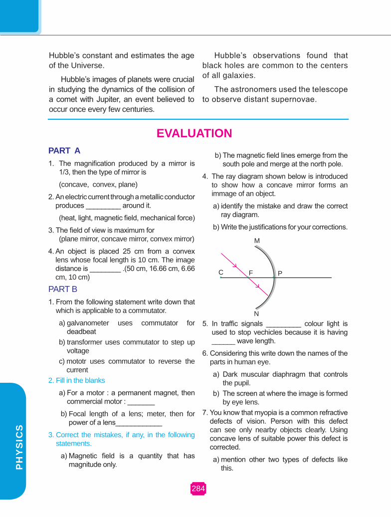
284
Hubble’s constant and estimates the age of the Universe.
Hubble’s images of planets were crucial in studying the dynamics of the collision of a comet with Jupiter, an event believed to occur once every few centuries.
PArT A1. The magnification produced by a mirror is
1/3, then the type of mirror is
(concave, convex, plane)
2. An electric current through a metallic conductor produces _________ around it.
(heat, light, magnetic field, mechanical force)
3. The field of view is maximum for (plane mirror, concave mirror, convex mirror)
4. An object is placed 25 cm from a convex lens whose focal length is 10 cm. The image distance is ________ .(50 cm, 16.66 cm, 6.66 cm, 10 cm)
PART B1. From the following statement write down that
which is applicable to a commutator.
a) galvanometer uses commutator for deadbeat
b) transformer uses commutator to step up voltage
c) mototr uses commutator to reverse the current
2. Fill in the blanks
a) For a motor : a permanent magnet, then commercial motor : _______
b) Focal length of a lens; meter, then for power of a lens____________
3. Correct the mistakes, if any, in the following statements.
a) Magnetic field is a quantity that has magnitude only.
b) The magnetic field lines emerge from the south pole and merge at the north pole.
4. The ray diagram shown below is introduced to show how a concave mirror forms an immage of an object.
a) identify the mistake and draw the correct ray diagram.
b) Write the justifications for your corrections.
Hubble’s observations found that black holes are common to the centers of all galaxies.
The astronomers used the telescope to observe distant supernovae.
EVALUATION
C F P
N
M
5. In traffic signals _________ colour light is used to stop vechicles because it is having ______ wave length.
6. Considering this write down the names of the parts in human eye.
a) Dark muscular diaphragm that controls the pupil.
b) The screen at where the image is formed by eye lens.
7. You know that myopia is a common refractive defects of vision. Person with this defect can see only nearby objects clearly. Using concave lens of suitable power this defect is corrected.
a) mention other two types of defects like this.P
HY
SIC
S

CH
AP
TE
R 1
7
MAgNETIC EFFECT OF ELECTrIC CUrrENT AND LIgHT
b) explain how can we correct it.
8. (a) Which of the compass needle orientations in the following diagram might correctly describe the magnet’s field at that point?
FUrTHEr rEFErENCE Books: 1. Fundamentals of optics
D.r. khanna and H.r. gulati r.Chand & Co 2. Magnetism Joy Frisch - Schnoll published by Creative Eduction.
3. Advanced physics keith gibbs Cambridge University press
Website: www.physics about.com
www.opticalsres.com www.newdn.com.
PART
–
C
1. (a) Label the following in the given diagram given below.
P
Q
B
A
S
RM’N’FE
G DM
H
N
I.
er
C
N S
ab
c
d (b) To an astronaut sky appears dark instead
of blue. Give the reason.
A D
B C
N S
RB1
B2
S2
S1
a) Incident ray b) Refracted ray c) Emergent ray d)Angle of refraction e) Angle of deviation f) Angle of emergence
1. (b) The retractive index of diamond is 2.42. What is the meaning of this statement in relation to speed of light?
2. a) Re draw the above diagram.
b) This diagram represents _________
c) Label the parts of the diagram.
d) Write the principle of the name of the device denoted by this diagram.
157285

286
SYLLABUS1. Applied Biology Heredity and Evolution :- Heredity –Variations-Evolution-Speciation-
Human evolution-Evolution tree-Genetic engineering-Bio technology and cloning-Stem cell-Organ culture-Microbial production-Biosensor – Bio chips-Science today – Gene therapy
2. Health and Hygiene
Immune System:- Health and its significance-Diseases and causes-Diseases caused by microbes and prevention-Modes of transmission-Immunization-Treatment and prevention-Biotechnology in Medicine-HIV and Prevention
3. My Body Structure & Function of the Human Body – Organ System:- Nervous system-Endocrine system-Cell division-Stages of Meiosis-Heredity
4. world of Plants reproduction in Plants:-Modes of reproduction - vegetative, asexual and sexual reproduction in plants-Pollination-Fertilization-Fruits and seeds formation-Seed dispersal
5. world of Animals A representative Study of Mammals- Morphology-Habitats-Adaptations-Basic Physiological Functions.-Circulatory system in man-Excretory system in man.-Relationship of structure to functions-Animal Behaviour - Behaviour (social, reproductive, parental care) -Some case studies from researchers(animals behavior)
6. Life Process Life Processes:- Definition-Types of nutrition and human digestive system-Respiration -Transportation in plants-water and minerals and animals - blood circulation-Excretion in plants and animals-Nervous system-Coordination in plants-Movement due to growth-Hormones in animals
7. Environmental Science - Ecology
Conservation of Environment:- Bio degradable and non bio degradable wastes-Water management-Wild life sanctuaries-Balance in Ecosystem-Coal and petroleum-Green chemistry-Science today – Towards a global village
8. Environmental Science – resource use and Management
waste water Management:- Journey of water-Sewage -Treatment -Domestic practices -Sanitation and diseases-Alternate arrangement for sewage disposal -Sanitation in public places-Energy Management-Energy audit (home, school)- Renewable sources (solar, hydrogen, wind)- Non–renewable sources—(coal, petroleum, natural gas)- Bio-fuels-generation & use-Energy Conservation & How we can help.
9. Matter Solutions:- Solute and Solvent-Types of Solutions-Solubility-Factors affecting – Solubility-Problems
10. Atomic Structure Atoms and Molecules:- Modern atomic theory- Avogadro Hypothesis- Atomicity-Relation between vapour density and molecular mass of a gas- Difference between-Atom and Molecules-Relative Atomic Mass- Relative Molecular mass-Mole Concepts- Mole- Definition-Problems based on mole conceptS
CIE
NC
E

287
SY
LLA
bu
S
11.Exploring Chemical Changes and Formulation
Chemical reactions:- Types of chemical reactions -Rate of chemical reaction-Factors influencing the rate of the chemical reaction-Acids- Classification of acids- Chemical properties of acids-Uses of acids-Bases-Classification of bases-Chemical properties of bases- uses of bases-Identification of acids and bases-pH scale-pH paper-Importance of pH in everyday life-Salts- Classification of salts-Uses of salts
12. Exploring Chemical Families
Periodic Classification of Elements:- Modern periodic law-Modern periodic table-Characteristics of modern periodic table-Metallurgy –Intro-duction-Terminologies in metallurgy-Differences between Minerals and Ores-Occurrence of metals- Metallurgy of Al, Cu and Fe- Metallurgy of Aluminium-Metallurgy of Copper- Metallurgy of iron- Alloys- Methods of making alloys-Copper Aluminium and Iron alloys-Corros ion -Method s of preventing corrosion
13. Exploring the world
Carbon and its Compounds:- Introduction-Compounds of carbon-Mod-ern definition of organic chemistry-Bonding in carbon and its compounds-Allotropy- Physical nature of carbon and its compounds- Chemical- prop-erties of carbon compounds-Homologous series-Hydrocarbons and their types -Functional groups- Classification of organic compound based on functional group-Ethanol-Ethanoic acid
14. Matter and Measurement
Measuring Instruments:- Screw Gauge-Measuring long-Distances – As-tronomical distance, light year
15. Forces and Movement
Laws of Motion and gravitation-Balanced and imbalanced forces-First law of motion-Inertia and mass-Momentum-Second aw of motion-F=ma-Third law of motion-Conservation of momentum and proof-Moment of force and couple-Gravitation Newton’s law of gravitation –Mass- Weight-Acceleration due to gravity-Mass of Earth-Science Today- Chandrayan, Cryogenic Techniques and Manned Space Station
16. Exploring Energy
Electricity and Energy:- Electric current and circuit-Electric potential and potential difference-Circuit diagram-Ohm’s law-Resistance of a conduc-tor-System of resistors -Heating effect of electric current-Joules law of heating-Role of fuse-Domestic electric circuits-Electric power-Chemical effect of electric current-Electrolysis electro chemical cells-Primary and Secondary cells-Sources of Energy-Conventional sources of energy-Non- conventional source of energy- Nuclear energy-Radioactivity- Nuclear fission and nuclear fusion-Nuclear reactivity advantages- Hazards of nuclear energy-Science today – Energy from seas.
17. Exploring Phenomena
Magnetic Effect of Electric Current and Light :-Magnetic field and magnetic lines of force-Magnetic field due to current carrying conductor-Magnetic field due to current carrying Straight conductor- Magnetic field due to current carrying Circular loop-Force on a current carrying conductor in a magnetic field-Fleming left hand rule -Electric motor-Electromagnetic induction- Faraday’s experiments-Electric generator –Light-Reflection of light by Spherical mirrors – image formation and Mirror Formula - Refrac-tion – Laws of refraction-Refractive index-Refraction by spherical lens-es- Image formation by lenses-Lens formula and magnification-Power of lens-Refraction of light through a prism-Dispersion-By a glass prism-Atmospheric refraction- Human eye –Defects and rectification-Science today –Hubble space telescope
18. Technology Practical and Projects

288
SC
IEN
CE
Design of Question Paper – X Std Science (Theory)Time: 2½ Hours Max. Marks: 75
The weightage of marks allotted for the design of question paper shall be as under:
A. weightage to Learning Outcome Sl.No Categories Mark PErCENTAgE
1 Knowledge 17 152 Understanding 52 453 Application 35 304 Skill 11 10
Total 115 100Note: (1) Total Marks is 115 inclusive of choice. (2) While preparing the question paper, there may be variations in weightage to the extent from 2 % to 5 %.
B. weightage given to various types of question S.No Types of Questions Marks
for Each Question
Total No. of
Questions
No. of Questionsto be answered
Total Marks
1 Section AObjective Type (OT) 1 15 15 15x 1=15
2 Section BShort Answer (SA) 2 30* 20 20x2 = 40
3 Section CLong Answer (LA)* 5 8 4 4 x 5 = 20
Total 53 39 75* Each Question may be split into 2 or 3 sub-divisions carrying 1, 2 or 3 marks. But the questions shall be from each area (Botany, Zoology, Chemistry, Physics). Choices will be internal (Either - or)
*Short Answer split upSl.No. Very Short Answer
Type of QuestionsTo be asked
1 To Match 32 To spot the error / mistake in the given statements 33 Reason and Assertion 34 To Raise questions 35 To label the parts in the given diagram 36 To copy a diagram & to identify /mark the parts 37 To calculate the required value(Problem solving) 38 To fill up the blanks (from the given pair of answers) 39 To interpret what happens in the given situations 310 To find the odd one out 3
Total Number of Questions given 30Total Number of Questions to be answered 20

289
SY
LLA
bu
S
C. weightage given to the higher order of questions
Sl.No Estimated higher order of questions % Percentage
1 Easy 502 Average 403 Difficult 10
D. weightage to Content Unit
Units
No. of QuestionsTotal
MarksOT SA LA
1. Heredity and Evolution
Bot
any
and
Zool
ogy
1(1) 1(2) 1(5)
23
82. Immune System 1(1) 1(2) 1(5) 83. Structure & Function of the Human
Body – Organ System - 3(2) - 6
4. Reproduction in Plants 1(1) 1(2) 1(5) 85. A representative Study of Mam-
mals - 3(2) - 66. Life Processes 1(1) 1(2) 37. Conservation of Environment 1(1) 1(2) 1(5) 88. Waste Water Management - 3(2) - 69. Solutions
Che
mis
try
1(1) 2(2) -
15
510. Atoms and Molecules - 1(2) 1(5) 711. Chemical Reaction 1(1) 2(2) 512. Periodic Classification of Elements 2(1) 2(2) 613. Carbon and its Compounds 1(1) 1(2) 1(5) 814. Measurements
15
-15. Laws of Motion and Gravitation
Phy
sics
1(1) 2(2) 1(5) 1016. Electricity and Energy 2(1) 3(2) 817. Magnetic Effect of Electric Current
and Light 2(1) 3(2) 1(5) 13
Total Number of Questions given 15(15) 30(60) 8(40) 53 115
Total Number of Questions to be an-swered 15(15) 20(40) 4(20) 39 75
() Indicates the marks

290
SC
IEN
CE
BLU
E Pr
INT
Uni
t
No.
Con
tent
Uni
tr
elat
ed
Subj
ect
kno
wle
dge
Und
erst
andi
ngA
pplic
atio
nSk
illTo
tal N
o.
of Q
ues-
tions
Tota
l
Mar
ksO
TSA
LAO
TSA
LAO
TSA
LAO
TSA
LA
1H
ered
ity a
nd E
volu
tion
Zoo
1(1)
1(2)
1(5)
38
2Im
mun
e Sy
stem
Zoo
1(1)
1(5)
1(2)
38
3
Stru
ctur
e &
Fun
ctio
n of
the
Hum
an B
ody
Hum
an B
ody
– O
rgan
Sy
stem
Zoo
1(2)
1(2)
1(2)
36
4r
epro
duct
ion
in P
lant
sB
ot1(
1)1(
5)1(
2)3
8
5
A r
epre
sent
ativ
e St
udy
of M
amm
als
Zoo
1(2)
1(2)
1(2)
36
6Li
fe P
roce
sses
Bot
& Z
oo1(
1)1(
2)2
3
7C
onse
rvat
ion
of E
nvi -
ronm
ent
Bot
1(1)
1(5)
1(2)
38
8w
aste
wat
er M
anag
e-m
ent
Bot
2(2)
1(2)
36
9So
lutio
nsC
he1(
1)1(
2)1(
2)3
5
10A
tom
s an
d M
olec
ules
Che
1(5)
1(2)
27
11C
hem
ical
rea
ctio
nC
he1(
2)1(
1)1(
2)3
5
12Pe
riodi
c C
lass
ifica
tion
of E
lem
ents
Che
1(1)
1(1)
1(2)
1(2)
46
13C
arbo
n an
d its
Com
-po
unds
Che
1(1)
1(5)
1(2)
38
14M
easu
rem
ents
Phy
--
15La
ws
of M
otio
n an
d g
ravi
tatio
nPh
y1(
2)1(
2)1(
5)1(
1)4
10
16El
ectr
icity
and
Ene
rgy
Phy
1(2)
1(1)
1(2)
1(1)
1(2)
58
17M
agne
tic E
ffect
of E
lec-
tric
Cur
rent
and
Lig
htPh
y1(
1)1(
2)1(
1)1(
2)1(
5)1(
2)6
13
Tota
l4(
4)4(
8)1(
5)8(
8)12
(24)
4(20
)2(
2)9(
18)
3(15
)1(
1)5(
10)
-53
115
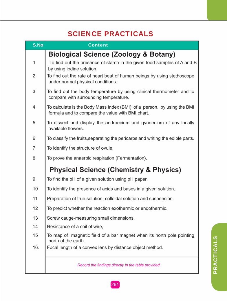
PR
AC
TIC
ALS
291
S.No Content
Biological Science (Zoology & Botany) 1 To find out the presence of starch in the given food samples of A and B
by using iodine solution.2 To find out the rate of heart beat of human beings by using stethoscope
under normal physical conditions.
3 To find out the body temperature by using clinical thermometer and to compare with surrounding temperature.
4 To calculate is the Body Mass Index (BMI) of a person, by using the BMI formula and to compare the value with BMI chart.
5 To dissect and display the androecium and gynoecium of any locally available flowers.
6 To classify the fruits,separating the pericarps and writing the edible parts.
7 To identify the structure of ovule.
8 To prove the anaerbic respiration (Fermentation).
Physical Science (Chemistry & Physics)9 To find the pH of a given solution using pH paper.
10 To identify the presence of acids and bases in a given solution.
11 Preparation of true solution, colloidal solution and suspension.
12 To predict whether the reaction exothermic or endothermic.
13 Screw cauge-measuring small dimensions.
14 Resistance of a coil of wire, 15
To map of
magnetic field of a bar magnet when its north pole pointing
north of the earth.16. Focal length of a convex lens by distance object method.
Record the findings directly in the table provided.
SCIENCE PRACTICALS
291

SC
IEN
CE
292
Zoology
Ex. No. 1 Date :
To find out the presence of starch in the given food samples of A and B by using Iodine solution.
Aim:
To find out the presence of starch in the given food samples of A and B by using iodine solution.
requirements:
Test tubes, Iodine solution.
Procedure:
Take 1 ml of foood sample A and B in separate test tubes.
Add one drop of Iodine solution in bothe the test tubes.
Observe the colour change and record.
Indication : Appearence of dark blue colour indicates the presence of starch.
Table:
Sl.No Food Sample Observation Presence / Absence of Starch
1 A
2 B
result:
The food sample__________________contains starch.

PR
AC
TIC
ALS
293
Ex. No. 2 Date :
To find out the rate of heart beat of human beings by using stethoscope under normal physical conditions.
Aim:
To find out the rate of heart beat of a person by using stetheoscope.
requirements:
Stethoscope, stop watch.
Procedure:
Use the stethoscope and hear Lubb and Dubb sound which make up a heart beat.
Count the number of heart beats per minute and record.
Table:
Sl. No Persons No. of heart beat per minute
1 A
2
3
4
5
Average :
Inference:
Under normal conditions the average human heart beat is found to be _____ per minute.
293

SC
IEN
CE
294
Ex. No. 3 Date :
To find out the body temperature by using clinical thermometer and to compare with surrounding temperature.
Aim:
To find out the body temperature of human being using clinical thermometer.
requirement:
Clinical thermometer, lab thermometer
Procedure:
Find out the room temperature by using lab thermometer.
Clean the Clinical thermometer in dilute dettol soaked cotton.
Shake the clinical thermometer at least four times.
Keep the mercury bulb of the clinical thermometer at the arm pit in boys or elbow in girls for a minute and record the temperature.
Repeat the same outside the room and record your findings for atleast three of your friends.
Table:
S.No Test Body Temperature oF
Room Temperature oC C=F-32 x 5/ 9
1Inside the room
Outside the room
2Inside the room
Outside the room
3Inside the room
Outside the roomInference: Under normal conditions the body temperature of human beings is
______oF, ______oC.
The body temperature of human beings remains the or same/ varies irrespective of surroundings.

PR
AC
TIC
ALS
Ex. No. 4 Date :
To calculate the Body Mass Index (BMI) of a person, by using the BMI formula and comparing the value with BMI chart.
Aim:
To calculate the BMI of any one of your classmates by using the BMI formula.
requirements:
Weighing machine, measuring tape.
Procedure: Find out the weight in kg of your calssmate by using weighing machine.
Find out the height of the same person and convert into meter2
By using the formula
weight in kg BMI = -------------- height in m2
Find out the BMI and record.
Note:
BMI 19-25 is normal , 26 and above is obese, below 19 is lean.
Table:
Sl. No Persons weight in kg Height in meter Height in meter2 BMI
1
2
3
Inference:
The BMI of my classmate Selvan/Selvi ______________is _______ and so he/she is normal / obese / lean.
295

SC
IEN
CE
296
BotanyEx. No. 5 Date :
To dissect and display the androecium and gynoecium of any locally available flowers.
To dissect and display the androecium and gynoecium of any locally available flowers.
Androecium
1) Androecium is the male reproductive part.
2) It has two parts, the filament and anther.
3) Pollen grains develop inside the anther.
Gynoecium
1) Gynoecium is the female reproductive part.
2) It has three parts, the ovary style and stigma.
3) Ovules are seen inside the ovary.
Separate the Androecium and Gynoecium of a given flower and paste in a separate sheet. Record your observations with regard to number of stamen shape of anther and shape of stigma in the given table.
Sl.no Name of the flower Androecium Gynoecium1.
2.
3.
4.
5.

PR
AC
TIC
ALS
297
Ex. No. 6 Date :
To classify the fruits. Separate the pericarps and write the edible parts and fill in the blanks
Simple fleshy fruits Berry - Tomato
1) The pericarp is divided into and .2) The mesocarp and endocarp remain .3) The edible part in tomato is .
Berry - Banana1) The pericarp is divided into and .2) The epicarp is and the mesocarp is .3) The edible part in banana is .
Hesperidium - Orange/Lemon.1) The pericarp is differentiated into layers.2) The outer glandular skin is .3) A middle thin whitish layer is .4) An inner membranous part is . 5) The juicy hairs or out growths are .
Pepo - Cucumber/ivy gourd (Kovai) 1) The pericarp is and .2) The mesocarp is .3) The edible part is
Drupe – Mango1) The number of seeds in mango is .2) Pericarp is differentiated into epicarp, ,
and 3) Epicarp is s , mesocarp is and
endocarp is in nature.4) Edible part of the mango is .
Drupe – Coconut1) The pericarp is differentiated into , and.2) The epicarp is thick, the mesocarp is , and the
endocarp is hard.3) The endosperm seen inside the is edible.
Classify the given fruits, record your observations in the given table.
Sl. No. Type of fruit of fruit Nature of pericarp Edible part
1.
2.
3.

SC
IEN
CE
298
Ex. No. 7 Date :
To identify the structure of ovule.
The given slide kept for identification is L.S. of ovuleThe charecteristics of ovule :
1) The ovule has layers of walls called as integuments.2) Inner to the integuments, is present.3) The embryo sac has , and
Observe the given slide and record your observations in the table :
Ex. No. 8 Date :To prove the anaerbic respiration (fermentation). Aim:
To prove the anaerobic respiration(fermentation)Materials required:
Test tube, sugar solution, yeast.Procedure: Sugar solution in a test tube is taken. A little quantity of yeast is added.
The tube is placed in a warm place–sunlight.
Record your observations and inference in the table given below :
Observation Inference
Sl.No Observation1.
2.
3.
Results: The alcohol smell indicates that the sugar is converted into alchohol
in the fermentation process

PR
AC
TIC
ALS
Ex. No. 9 Date : To find the pH of a given solution using pH paper. Aim:
To find the pH of the given solution using pH paper.
Materials and Apparatus required:
Test tubes, test tube stand, test tube holder, pH paper, dil. HCl, dil. NaOH, lemon juice, water, baking soda solution, vinegar etc.
Procedure:
Take about 10 ml of the given samples in different test tubes and label them as A, B, C, D, E and F. Dip the pH paper into the test tubes and compare the colour of pH paper with the colour chart of pH reference. Note the approximate value of pH.
Table:
Test tubes SamplepH paper Nature of solution
Colour produced
Approximate pH
A c i d i c / B a s i c / Neutral
A
B
C
D
E
F
Chemistry
299

SC
IEN
CE
300
Ex. No. 10 Date :To identify acids and bases Aim To identify the presence of an acid or a base in a given sample.
Materials and apparatus required :Test tubes, test tube stand, glass rod, litmus paper (both red and blue), acids, bases, phenolphthalein, methyl orange solution.
Note: • All acidic solutions are colourless in phenolphthalein, pink in methyl orange and turn blue litmus paper to red.• All basic solutions are pink in phenolphthalein, straw yellow in methyl orange and turn red litmus paper to blue.
S.No Experiment Observation (Colour change)
Inference (Acid/base)
1
Take 5 ml of the test solution in a test tube, add phenolphthalein in drops to this content.
2
Take 5 ml of the test solution in a test tube and add methyl orange in drops.
3
Take 10 ml of the test solution in a test tube and dip litmus paper into the test tube.

PR
AC
TIC
ALS
Ex. No. 11 Date :Preparation of true solution, colloidal solution and suspensionAim : To prepare true solution, colloidal solution and suspensionMaterials and apparatus required : Beakers, common salt, table sugar, starch, chalk powder, sand, egg albumin. Procedure:
Beaker Observation Inference
Take 20ml of water in three different beakers and label them as A, B & C. Add common salt in A,
starch in B, and chalk power in C. Stir the contents of three different beakers gently. Record your
observations.
Note :
i.
A.
B.
C.
If the particles do not settle down at the bottom and pass through the filter paper easily the solution is said to be a true solution.
ii. If the particles do not settle down but they form turbid solution then the solution is said to be a colloidal solution.
iii. If the particles settle down to form sediments leaving behind residue on the filter paper then the solution is said to be a suspension.
result : True solution is in beaker _____________
Colloidal solution is in beaker __________
Suspension is in beaker ______________
301

SC
IEN
CE
302
Ex. No. 12 Date :
To predict whether the reaction is exothermic or endothermic.experimentAim. To predict whether a reaction is exothermic or endothermic using
the given chemicals
Materials and apparatus required Test tubes, test tube stand, water, glass rod, sodium hydroxide
(pellets),ammonium chloride etc.Note: • Exothermic reaction evolves heat • Endothermic reaction absorbs heat
S.No Experiment Observation( hot/cold) Inference(exo/endo)
1
Take water in a test tube. Add sodium hydroxide pellets one by one followed by stirring. Touch the test tube and note the observation.
2
Take water in a test tube. Add ammonium chloride salt and stir well .Touch the test tube and note the observation.

PR
AC
TIC
ALS
PHYSICS
Ex. No. 13 Date :
SCrEw gAUgE - Measuring small dimensions of the object
Aim:
To find the radius of the given wire.
Apparatus required :
Screw gauge, a uniform thin metal wire.
Formula :
Radius of the wire r = d/2, d – diameter of the wire.
S2 S1 Hallow Cylindrical tubeMilled Head (H)
Safety device (D)(Ratchat)
Head Scale
Index line
U-Shaped Frame pitch scale
Procedure :
The least count of the screw gauge is found .Zero error of the screw gauge is found in the following way. The plane surface of the screw and the opposite
303

SC
IEN
CE
304
plane stud on the frame are brought in to contact. If zero of head scale coincides with the pitch scale axis, there is no zero error.
If the zero of the head scale lies below the pitch scale axis, the zero error is positive. If the n th division of the head scale coincides with the pitch scale axis
ZE = + (n × LC )
Then the zero correction ZC = - (n × LC )
If the zero of the head scale lies above the pitch scale axis, the zero error is negative. If the n th division of the head scale coincides with the pitch scale axis
ZE = - (100 – n) × LC
Then the zero correction ZC = + (100 – n) × LC
Place the wire between two studs. Rotate the head until the wire is held firmly but not tightly . Note the pitch scale reading(PSR) and the head scale division which coincides with the pitch scale axis (HSC). The diameter of the wire is given by PSR + (H.S.C × LC) + ZC. Repeat the experiment for different portions of the wire. Tabulate the readings. The average of the last column readings gives the diameter(d) of the wire.The value d/2 gives the radius of the wire.
Table:
L.C = Z.E = Z.C =
S.No P.S.R (mm) H.S.C H.S.C × L.C
Total readingP.S.R +(H.S.C ×L.C) ± Z.C (mm)
1
2
3
Mean =
The radius of given wire r = d/2
result :
The radius of the given wire = mm

PR
AC
TIC
ALS
Ex. No. 14 Date :
rESISTANCE OF A wIrE
Aim To determine the resistance of the given wire .
Apparatus required
A battery(2 V), ammeter(1.5 A), voltmeter(1.5 V), key, rheostat, experimental wire(1 Ω or 2 Ω) and connecting wires.
Formula
V Resistance of the wire R = –– I
V is the potential difference across the wire.
I is the strength of the current through the experimental wire.
k Rh(•)
305

SC
IEN
CE
306
Procedure
Connect the battery eliminator, ammeter the given wire, rheostat and key in series. The voltmeter is connected in parallel connection across the given wire. The circuit is closed and the rheostat is adjusted such that a constant current flows through the given coil of wire. The current is noted as ‘I’ from the ammeter and the potential difference across the wire V is noted from the voltmeter. The value V/I gives the resistance of the wire. The experiment is repeated for different values of the current.
VThe average value of –– gives the resistance of the wire R. I
Tabulation
Trial No Ammeter reading I (ampere)
Voltmeter readingV (volt)
resistanceR = V/I (ohm)
12345
Mean r =
result
Resistance of the given wire R = –––––––– ohm.

PR
AC
TIC
ALS
Ex. No. 15 Date :
MAPPINg OF MAgNETIC FIELD
Aim:
To map the magnetic lines of force when the bar magnet is placed with its north pole facing geographic north
Apparatus required:
Drawing board, drawing pins, bar magnet, small magnetic compass needle and white sheet.
Procedure:
A sheet of paper is fixed on a drawing board. Using a compass needle, the magnetic meridian is drawn on it. A bar magnet is placed on the magnetic me-ridian such that its north pole points towards geographic north. The north and south poles of the compass are marked by pencil dots. The compass needle is shifted and placed so that its south pole touches the pencil dot marked for the north pole. The process is repeated and a series of dots are obtained. The dots are joined as a smooth curve. This curve is a magnetic line of force. In the same way several magnetic lines of force are drawn around the magnet as shown in figure. The magnetic lines of force is due to the combined effect of the magnetic field due to bar magnet and the Earth.
result: The magnetic lines of force are maped when the bar magnet is placed with
its north pole facing geographic north. The maped sheet is attached.
307

SC
IEN
CE
308
SC
IEN
CE
Ex. No. 16 Date :FOCAL LENgTH OF CONVEx LENS
Aim To determine the focal length of convex lens by distant object method
Apparatus required The given convex lens, lens stand, white screen and meter scale Procedure
ƒ1,ƒ2, ƒ3, are the focal lengths measured by focucing different distant objects.
Distant object methodThe convex lens is mounted on the stand and is kept facing a distant object(may be a tree or a building). The white screen is placed behind the convex lensand its position is adjusted to get a clear, diminished and inverted image of theobject. The distance between the convex lens and the screen is measured. Thisgives an approximate value of the focal length of the convex lens.
ƒ1+ ƒ2+ ƒ3
3Formula : Focal length ƒ =
S.No Distant object Distance between the convex lens and the screen
1 Tree f1
2 Building f2
3 Electric pole f3
Mean =
Image f Lens
Parallel rays from distant object
.result:
Focal length of the given convex lens f = ––––––––––––––-cm