1111111111111111111111111111111111111111111111111111111111...
TRANSCRIPT
United States Patent [!9J
Peli
[54] HALFTONE IMAGING METHOD AND APPARAUTS UTILIZING PYRAMIDOL ERROR CO!Ioo'VERGENCE
[75] Inventor: Eli Peli, Newton, Mass.
[73] Assignee: Eye Research Institute of Retina Foundation, Boston, Mass.
[21] Appl. No.: 540,685
[22] Filed: Jun. 20, 1990
[51} Int. CJ.s ......................... H04N 1/23; H04N 1/40 [52] u.s. Cl ..................................... 358/298; 358/443;
358/458; 358/465; 358/466 (58} Field of Search ............... 358/298, 443, 455, 456,
358/457, 458, 463, 465, 466
[56] References Cited
U.S. PATENT DOCUMENTS
4,339,774 7/1982 Temple ............................... 358/456 4,384,336 5/1983 Frankie et al. ........................ 382/49 4,742,399 5/1988 Kitamura ........................ 358/466 X 4,750.211 6/1988 Wray ..................................... 382/41 4,876,611 10/1989 Fischer et al. ... , .................. 358/456 4,878,125 10/1989 Katayama ........................... 358/443 4,920.501 4/1990 Sullivan et al. ................. 358/463 X 4,924.322 5/1990 Kurosawa et al. ............. 358/463 X 4,975,786 12/1990 Katayama et al. .................. 358/459
OTHER PUBLICATIONS
Jarvis et a!., "A Survey of Techniques for the Display of Continuous Tone Pictures on Bilevel Displays," Computer Graphics and Image Pwcessing. vol. 5, pp. 13-40, 1976. Jarvis et al., "A New Technique for Displaying Continuous Tone Images on a Bilevel Display," IEEE Transactions on Communications. pp. 891-898, Aug. 1976. Peli, "Visual Issues in the Use of Head Mounted Displays," Proceedings of the SPIE. vol. 1099, Visual Communications and Image Processing IV, 1989. Roetling. "Quality Measures in Digital Halftones," Optical Soc. of Am., Washington, D.C., Topical Meeting on Applied Vision, 1989, Technical Digest Series, vol. 16, pp. 59-62. Roetling, "Halftone Method with Edge Enhancement and Moire Suppression," JOSA, vol. 66, pp. 985-989, 1976.
UIT-TM! JUlES
...
111111111111111111111111111111111111111111111111111111111111111111111111111 US005109282A
[II] Patent Number: 5,109,282 [45] Date of Patent: Apr. 28, 1992
Roetling, "Visual Performance and Image Coding," SPIE, vol. 74 (Image Processing) p. 195, 1976. Saghri et a!., "Personal Computer Based Image Processing with Halftoning," Opto Eng., vol. 25, pp. 499-504, 1986. Ulichney, "Dithering with Blue Noise," Proceedings of the IEEE, vol. 76, No. 1, Jan. 1988, pp. 56-79. Ulichney, "Digital Halftoning," MIT Press, Cambridge, Mass., 1987. Hou, "Digital Halftoning and Shading in Digital Docu-. ment Processing," John Wiley & Sons, N.Y., 1983, pp. 83-115. Bayer, "An Optimum Method for Two Level Rendition of Continuous-Tone Pictures," Proc. IEEE Int. Conf. on Communications, Conf. Rec., pp. 26-11, 26-15, 1973. Floyd et a!., "Adaptive Algorithm for Spatial Gray Scale," Proc. SID, vol. 17, pp. 75-77, 1976. Carlsohn eta!., "Adaptive Selection of Threshold Matrix Size for Pseudogray Rendition of Images," Optical Engineering, vol. 24(4), pp. 655-662, Jul.-Aug. 1985. Anastassiou et a!., "Progressive Halftoning of Images," Electronics Letters, vol. 24, pp. 489-490, 1988.
Primary Examiner-Benjamin R. Fuller Assistant Examiner-Eric Frahm Attorney, Agent, or Firm-Lahive & Cockfield
[57] ABSTRACT
Apparatus and methods for converting continuous grey tone images into high resolution halftone images utilize an iterative, multi-level, multi-resolution error convergence process. The continuous grey tone image is first binarized. At each level of the process, the binarized image is compared with the grey tone image over a larger window of pixels. Within each window, selected binarized image pixels are tested for possible change in binary assignment. The binary assignment of a given test pixel is changed if the change would result in a lower average error over the entire window. By varying the selection of test pixels, the process can provide clustered dot patterns and dithering.
STII(I Utr·TN! IIIJ/f·fU£ JIJ;[S
(List continued on next page.)
3 Claims, 18 Drawing Sheets
IIILf·fll! !IItts
+

5,109,282
Page 2
OTHER PUBLICATIONS
Anastassiou et al., "Digital Image Halftoning Using Neural Networks," SPIE Visual Communications and Image Processing. vol. lOCH, pp. 1062-1068, 1988. Allebach and Liu, "Random Quasiperiodic Halftone Process," Journal of the Optical Society of America, vol. 66, No.9, pp. 909-917, Sep. 1966. Brightfield, "A One-Chip Real-Time Convolution Solution,'' FSD: The Electronic System Design Magazine, pp. 47-52, May 1989. Goldstein et al., "Medical Image Communication Using
Halftone Algorithms," (unpublished). Stevenson and Arce, "Binary Display of Hexagonally Continuous-Tone Images," Journal of the Optical Society of America, vol. 2, No.7, pp. 1009-1013, Jul. 1985. Werman and Peleg, "Halftoning as Optimal Quantization", Center for Automation Research, University of Maryland, Jan. 1986. Sundial, vol. 14, No. 4, Dotti, ed., Eye Research Institute of Retina Foundation, Dec. 1988, pp. 6-9. Independent Living Aids, Plainview, N.Y., (Product Catalog), -advertises portable electronic magnifying viewers.
U.S. Patent Apr. 28, 1992 Sheet 1 of 18 5,109,282
~ ~~
CJ ~
CJ CJ ~~__. ...... ~ ~-
\ I \ I ~ ~ ~
~ ~~--- ~~ "' ~ ~~~ ~~ ~ ~~~ ~"') c::s ~
~ ~ ~~
~ ~~ ~· ~ !-') "'-.
~~~ ~ ...... ~ ...... ~ ...... ~~~
~ ~~~ ~ ·~~~ ........... \.~')~-.....;
~ DATA DATA ~ ~ ~
~ ~ ~~~ ·~·~~ ~ HEAD :~..... "'-.;at~
~ ~"'~ HEQIJEST ~ ~ ~
::.t ~
~ ~
~ ~~ ~ ~ ~~ • ~~
~ ~ ~ ~ ~~
..;:::~ ~~~ ~~-+ ·~~
""'"" :~.....~~
~ ~ ~ ~ ~ ..... ~~ ~
~\.S ~~~ ~c:::;"
' \\\11! <J
U.S. Patent Apr. 28, 1992 Sheet 2 of 18 5,109,282
~ •
~
~ ~~~ ~~
~~~ ~~~
~ ........ ~ ~ ......... ~ ~~~ ~
U.S. Patent Apr. 28, 1992 Sheet 3 of 18 5,109,282
~ ~
::a.::" ~ " ~ ~ "') ~ ...... ~ ~ ~ ~ ~~ ~ cc ~~ ~ ~ ~~
~ ~~ "'- ~~ ......., .......,~
·~ ~ ~ ~ ,) ~ .. ~ ~ ......., ~"
~ ~ ~ ~
-....;: ~ l:lit~~~
~ ~~~~ ~ -- ~ ~ ~~,
~~ q__ V) ~ ~ ~ ~~ ~ --~ ~ ~ ~ ~ ••• • ~ ~ ~ ~ ~
~ ~ ~ ~ ~ ~
~ ~ ~<"') ....... 0) ......., ... ... ... ~
~<"') ....... 0)
~ ~ ~ ~
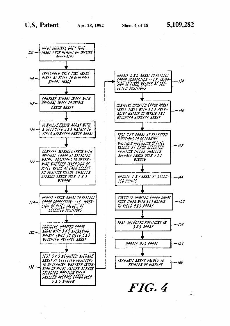
U.S. Patent Apr. 28, 1992 Sheet 4 of 18 5,109,282
INPUT ORICIIIAL CREY TOllE 100 - IJIACE !RON NEJIORY OR INACIIIC
APPARATUS
~ THI?ESHOLD CREY TOllE /IIACE UPDATE 515 ARRAY TO REfLECT - PilEI BY PllEL TO CENERATE
~ ERROR CORRECTION --1£,/NJIER-BINARY IIIACE SION Of PllEL JIALUES AT SEL-
1--110 134
~ ECTED POSITIONS
~ COIIPAI?E BINARY IIIACE 1'/TH - ORICINAL IIIACE TO OBTAIN CONJIOLJIE UP/JATE/J ERRORARRAY ERROR ARRAY THREE TillES I'ITH J I J AJIER- -Ill
~ ACINC NATR/l TO OBTAIN 111 II'EICHTED AJIEI?ACE ARRAY
CtJNJIOL Jl[ ERROR ARRAY If/Til ~ ·- A SELECTED J I J NATR!l TO 1!0 YIELD AJIERACE/J ERI?OR ARRAY TEST 111 AI?RAY AT SELECTED
~ POSIT/OilS TO /JETERNINE /I'HETHER INJIERSION Of !'liEf -. JIALUES AT EACH SELECTED 14?
CONPARE AJIERACEDERROR lf!TH I'OSIT/011 YIELDS SJIALLER ORICINAL EI?ROR AT SELECTED AJIEI?ACE ERI?OR OJIER 111
·- NATR!)' I'OSITIOIIS TO /JETER- 1'111/JOI' IIIII[ II'HETHER IIIJIERS/011 Of
~ PIIEL JIALUE AT EACH SELECT-f/J !'OSITION YIELDS SNALLER
I!?
AJIEI?ACE EI?ROR OJIER J I J UP/JATE l l l ARRAY AT SELEC- 144 ~' /f!N/JOI' Tf/J POl/ITS
~ ~ UPDATE ERROR ARRAY TO REfLECT COIIJIOLJIE Ul'fJATE/J ERROR ARRAY
1?4 ·- ERROR CORRECT/Oll--IE, INJIER- fOUR TIJI[S lf!TH JIJ IIATR/l ~ !50 S/011 Of PIIEL JIALUES AT Tti YIEL /J 9 I! ARI?A Y
SELECTED I'OSITIONS 1 ~ TEST SEL(CTED POSITIONS IN
COIIJIOLJIE UPDATED ERROR g,rg ARRAY ~ 15?
- ARRAY lf!TH J I J AJIERAC!NC
+ NATR/1 Tlf!CE TO YIELD 515 lffiCHTED AJIERACE AI?RAY
IJD
~ UI'/JATE g,rg ARRAY
~ TEST 515 I'EICHTE/J AJIERACE
!54
ARRAY AT SELECTED I'OS!TIONS TI?AKSIIIT AI?I?AY YALUES TO ~ TO DETEI?HINE I'HETHER IKJIEI?- PRINTER OR /JISI'LAY - SION Of !'liEf JIALUES AT EACH 1---/J?
160
SELECTED I'OSITIOK YIEL/J SIIALLER AJIERACE ERROR IJJIER
5 I 5 1'/N/JOI'
FIG.4

U.S. Patent Apr. 28, 1992 Sheet 5 of 18 5,109,282
FIG. 5A
FIG.5B
U.S. Patent Apr. 28, 1992 Sheet 6 of 18 5,109,282
FIG.5C
FIG.5D
U.S. Patent Apr. 28, 1992 Sheet 7 of 18 5,109,282
FIG,5E
FIG. 5F f f/1/tJ/1 AI?! J
U.S. Patent Apr. 28, 1992 Sheet 8 of 18 5,109,282
3 3 3 3 3 3 3
5 7 5 7 5 7
3 3 3 3 3 3 3
5 9 5 5
3 3 3 3 3 3 3
5 7 5 7 5 7
3 3 3 3 3 3 3
9 5 5 9 5
3 3 3 3 3 3 3
5 7 5 7 c 5 7
3 3· 3 3 3 3 3
5 9 5 5
3 3 3 3 3 3 3
5 7 5 7 5 7
3 3 3 3 3 3 3
9 5 5 9 5
3 3 3 3 3 3 3
5 7 5 7 5 7
FIG.6
FIG.7

U.S. Patent Apr. 28, 1992 Sheet 9 of 18 5,109,282
3 7 3 3 7 3 3 7 3 3
5 5 5 !
3 !3 3
9 5 5 9
3 7 3 3 7 3
5 5 5 5
3 3 3 3 3 3
.···s·-.,. <:·-;, .. ~··>.-. <~<. .. :·. ;~,·<x .... >~--; / / .. ·' /// 5 9 · .. ' ·I', e ..... . x: .. ·"'/ ...q .. .--_ / .. '
3 3 7 3 3 7 3
5 5 5
3 3 3 3 3 3
5 9 5 5 9 5
3 7 3 3 7 3 3 7 3 3
5 Is 5 5 5
FIG,B
FIG,9
U.S. Patent Apr. 28, 1992 Sheet 10 of 18 5,109,282
FIG.JO
FIG.JJA ( f/?101? A/?1)
U.S. Patent Apr. 28, 1992 Sheet 11 of 18 5,109,282
":
'· •.:.;. .. '~-
FIG.JJB (PI? 101? AI? T)
~~~iM'····.•····•(. :·c:··c~;f!G:':W":~ .• ·.,
-:.-:-.:···.
FIG.JJC
U.S. Patent Apr. 28, 1992 Sheet 12 of 18 5,109,282
•
FIG. 12A f f/?101? AI? T)
FIG. 12B f P/?101? AI?!)
U.S. Patent Apr. 28, 1992 Sheet 13 of 18 5,109,282
FIG.J2C
'
FIG.J3A f P/?101? AI?T J
U.S. Patent Apr. 28, 1992 Sheet 14 of 18 5,109,282
FIG.l3B ( ?1?101? AI?TJ
FIG.J3C
U.S. Patent Apr. 28, 1992 Sheet 15 of 18 5,109,282
FIG.J4A ( f/?101? ART J
FIG. 14B
U.S. Patent Apr. 28, 1992 Sheet 16 of 18 5,109,282
""' ~ -...;.
::..... ~ ~ ~ ~ ~
I?AfJIALLY AJIEI?ACEtJ PfJifff( SPECTI?IJN ffJI?; = 1/J
6~------------------~~----~
fJ Ill 1/Vl
I?AfJIAL fi?EQtJEIICr (1//IITS fJf 1/SJ
FIG.J4C ~ v"fJIIJIEIIT!fJIIAL El?l?fJI? P/?fJPACAT!fJ/1 -+- Pfi?AN/i? ( I?AIIfJfJH!lfi?)
AII!SfJ!I?fJPf f(J/?; "1/J
J(J~~---------------=-------
l(J
/()
()
-!()
-lfJ-L---------------__.J fJ Vl t 1/Vl
I?Ai?IAL fi?EQIJEIICY (1/11/!S (Jf 1/SJ ;
FIG.J4D ---o- CfJIIJI!IIT!tJIIAL El?l?fJI? P/?fJPACA!IfJ/1 -o-llfJIII?AIIDfJN!lfi? ---• -I?AIIfJfJNIZED

U.S. Patent Apr. 28, 1992 Sheet 17 of 18 5,109,282
FIG, 15A ( fl?!tJI? AI?! J
FIG, 15B
U.S. Patent Apr. 28, 1992 Sheet 18 of 18 5,109,282
HAIJIALLY AJIEHACEIJ POI'EH SPECTHUII fOR / 6 11/G
0~~--------------~ 0 jg Ill llvl
I?A/JIAL fi?E~!JEIICYfUIIITS Of /ISJ -"'--<>-- COIIJI[IIT!OIIAL El?/?0/? P/?OPACAT/011
FIG.l5C • PY/?ANIIJ fi?AIIIJON!lf!JJ
A/1/S(}T/?OPY ftJ/? g=/116 M~-----------------------------.
c
c lO
~
' 10 ' • ~
~ "<::
~ 0 ~ ' ~ ~ ~ -10
-N~-----------------------------0 f; til llvl
HAIJIAL f/?EQUEIICY (!/lilTS Of IISJ --o- COIIJIEIITIOIIAL ERROl? P/?OPACAT/011
F., TG 15D 0 11011 HAII!JONIZEIJ ~ ~ • - • I?AIIIJONIZEIJ
1/
1 5,109,282
HALITO:SE IMAGI:SG METHOD A:SD APPARAUTS UTILIZI:SG PYRA!\IIDOL ERROR
CO:SVERGE:SCE
BACKGROUND OF THE INVENTION s
2 tiona! methods produce output images with objectionable visual artifacts. These artifacts can result from limited dynamic range or limited spatial resolution in the output image.
Halftoning methods can be divided into four categories: (1) dithering techniques, (2) constrained average or
This invention relates generally to systems for image edge emphasis techniques, (3) error diffusion or propa-processing, and, more particularly. relates to apparatus gation techniques, and (4) adaptive methods. A review and methods for visually enhanced depiction of multi- of the first three classes and a comparison of their per-valued grey tone images on binary display devices or 10 formance is found in Jarvis et a!., cited above. print media. Dither halftoning methods generate a binary image
Digital halftoning methods and apparatus have by comparing the original image value to a position gained considerable attention in recent years. These dependent set of thresholds within a small repeated cell techniques are widely used for rendering "continuous containing an NXN array of pixels. This technique is tone" or multi-valued grey tone images on binary dis- 15 discussed in Hou, Digital Halfioning and Shading in play devices or printers. When applied to a continuous Digital Document Processing, John Wiley & Sons, New tone image, halftoning generates a binary image in York, 1983, pp. 83-115. The selection of the threshold which the average density locally simulates that of the values and the positions of the threshold values within continuous tone image. Digital halftoning is frequently the cell determines the type of dither technique, In utilized in the desktop publishing field, in connection 20 particular, the position of the threshold values within a with computers that prepare images for printing. Due to cell can be random or ordered, and the position of the the limited resolution of conventional laser printer- dots within the ordered screen can be dispersed across s-typically 300 dots per inch-the visual quality of the cell or clustered together. laser-printed halftone images is dependent upon the In applications utilizing printers or other devices in method used to process the image. 25 which the fidelity of single dot reproduction is low,
In addition to printing, halftone images are used to clustered dots and ordered screens produce better re-display visual information on computer binary monitors suits than do dispersed dots and random screens. In
~?s~l1~~~~ri~ij~~~~! :tis~~a~~ ~~~~e:i~~~~c~~~~~e:s ~~~ clustered dot methods, diagonally oriented patterns are the Display of Continuous Tone Pictures On Bilevel 30 preferred because of the limited sensitivity of the human Displays," Computer Graphics and Image Processing, visual system (HVS) to diagonal patterns. This is dis-Yo!. 5, pp. 13-40, 1976. The advent of miniature, head- cussed in Ulichney, Digital Halfioning. MIT Press, mounted binary display devices of moderate resolution Cambridge, Mass., 1987. has also generated increased interest in halftoning meth- Dispersed dots and ordered screens are preferred for ods and apparatus. See Peli, "Visual Issues in the Use of 35 use with devices having reliable dot reproduction, be-Head Mounted Display," Proceedings of the SPIE. Vol. cause dispersed dots provide increased spatial resolu-1099. Visual Communication and Image Processing IV, tion at a given dynamic range of gray levels. One 1989). method of dispersing the dots is proposed in Bayer, "An
Additionally, the continuing development of Optimum Method for Two Level Rendition of Continu-telecopiers, picture phones and other systems involving 40 ous-T one Pictures," Proc.IEEE Int. Conf on Communi-high-speed transmission of visual images over limited cations. Conf Rec., pp. 26-11, 26-15, 1973. The Bayer bandwidth communication channels has augmented the method alternates horizontal, vertical, or diagonal need for enhanced halftone imaging. Halftoning tech- points at each gray step. A significant limitation of the niques provide data compaction by generating a com- Bayer method of dispersed-dot dithered halftoning, pressed form of visual information suitable for efficient 45 however, is the distinct visibility of certain textures that transmission over limited capacity channels. This appli- produce the appearance of false contours in some im-cation of halftoning is discussed in Roetling, "Quality ages. Measures in Digital Halftones", Optical Soc. of Am., Constrained average methods typically provide Washington, D.C., Topical Meeting on Applied Vision, greater apparent resolution than that afforded by dither 1989, Technical Digest Series, Vol. 16, pp. 59-62; and so techniques, with a consequent reduction in aliasing. Anastassiou et a!., "Digital Image Halftoning Using These methods are discussed in Roetling, "Halftone Neural Networks," SPIE Visual Communications and Method with Edge Enhancement and Moire Suppres-Jmage Processing. Vol. 1001, pp. 1062-1068, 1988. sion," JOSA, Vol. 66, pp. 985-989, 1976; and in Jarvis et
Conventional halftone methods impose a compromise a!., "A New Technique for Displaying Continuous between spatial resolution and dynamic range-i.e., the 55 Tone Images on a Bilevel Display", IEEE Transactions number of grey tones represented-and the necessity of on Communications, August 1976, pp. 891-898. Con-maintaining visually pleasing image texture and per- strained average techniques enhance the appearance of ceived roughness. This compromise is discussed in edges by calculating local averages and adjusting the Saghri et a!., "Personal Computer Based Image Pro- dither threshold value locally. The effect is equivalent cessing With Halftoning," Opt. Eng .. Vol. 25, pp. 60 to locally reducing the modulation of the halftone 499-504, 1986; and Ulichney, "Dithering With Blue screen, which reduces the number of possible gray lev-Noise," Proceedings of the IEEE, Vol. 76, No. I, Janu- els. In the Roetling method, local averaging is per-ary 1988, pp. 56-79. formed over the binary images and the original image.
Visually acceptable output images can be obtained Jarvis et a!. perform local averaging over the original through conventional digital halftoning methods if ex- 65 image only. tremely high resolution displays or printers are avail- Error diffusion or error propagation methods utilize able. However, when commonly available, moderate- no fixed, repeated cell of pixels. Instead, these tech-resolution printers or displays are employed, conven- niques involve pixel-by-pixel gray scale control pro-

3 5,109,282
4 of Images," Electronics Letters, Vol. 24, pp. 489-490, 1988.
The same authors propose a symmetric error diffusion neural network in which error values from all neighboring points are applied to calculate the binary value at a central point. The process is parallel and recursive in nature, and is intended to be implemented in neural net devices. See Anastassiou, et al., "Digital Image Halftoning Using Neural Networks," SPIE Vi-
cesses, in which selected gray tone pixel values are switched from black to white or from white to black. See Floyd et al., "Adaptive Algorith!J.l for Spatial Grey Scale," Proc. SID. Vol. 17, pp. 75-77, 1976. Each time a gray tone pixel value is switched to white or black, a 5 local error in the gray scale is generated. The error is then redistributed among local pixels to correct the image. This approach tends to increase dynamic range and provide enhanced spatial resolution, thereby suppressing aliasing. See Saghri et al., cited above. Error propagation techniques are inherently serial, with error values being determined solely on the basis of previously-processed pixel values.
10 sua/ Communications and Image Processing. Vol. 1001, pp. 1062-1068, 1988.
Ulichney (1988), cited above, addresses various methods for implementing the error propagation technique, 15
in order to select the approach most suitable for representing a region of uniform gray level. Optimum results are obtained when the output image has certain blue noise characteristics. This effect can be achieved by modifying the basic error propagation method with a 20
serpentine raster and Floyd filtering with fifty percent random weights. See Floyd, cited above. When the error propagation process is executed on a serpentine raster, the cumulative error determination is limited to 25 no more than half of the neighborhood of any point. This process reduces the apparent texture patterns that appear when the unmodified error propagation technique is used.
Although error propagation methods can provide 30 acceptable results, the computational complexity of the method increases with the area over which the error is permitted to propagate. This complexity, combined with the inherent serial execution of the method, results in excessive processing time, even for moderate size 35 images.
Recently proposed systems for enhancing the speed and quality of halftone image generation include adaptive coding, progressive coding. and parallel processing. Adaptive coding systems assign additional gray levels 40 are to areas of an image having low spatial frequency content, while assigning fewer gray levels to areas of high spatial frequency. An example is discussed in Carlson et al., "Adaptive Selection ofThreshold Matrix Size for Pseudogray Rendition oflmages," Optical Engineer- 45 ing. Vol. 24(4), pp. 655-662, July-August, 1985.
Adaptive coding is based upon differences in the number of grey levels that the human visual system can detect at each spatial frequency. These differences, and the corresponding desirability of locally varying the 50 resolution and dynamic range of halftone images, is analyzed in Roetling. "Quality Measures in Digital Halftones", Optical Soc. of Am., Washington, D.C., Topical Meeting on Applied Vision, 1989, Technical Digest Series, Vol. 16, pp. 59-62; and Roetling, "Visual 55 Performance and Image Coding," SPIE, Vol. 74 ("Image Processing") pg. 195 (1976).
Progressive coding systems divide each image into different classes of images at various resolutions. The various classes are progressively coded or binarized, 60 and the binarization may be performed in parallel within each class of images, based on values of previously calculated classes. The process combines aspects of the ordered dither method and the error propagation technique, as each position threshold is determined on 65 the basis of error values propagated from previously processed neighboring pixels. Progressive coding is analyzed in Anastassiou et al., "Progressive Half-toning
Conventional adaptive or progressive coding sys-tems, however, typically do not provide sufficient processing speed for real-time halftone image generation. Moreover, the error diffusion neural network system requires a complex array of special-purpose digital pro-cessors. Such networks are expensive and not widely available.
It is accordingly an object of the invention to provide improved halftone imaging methods and apparatus that incorporate the respective advantages of the various classes of techniques discussed above.
A further object of the invention is to provide halftoning methods and apparatus enabling enhanced image rendition by printers and monitors having limited resolution-i.e., on the order of 512X512 pixels.
It is another object of the invention to provide such methods and apparatus that reduce or eliminate the visual artifacts introduced by conventional methods of dithered halftoning.
Another object of the invention is to provide apparatus and methods for high-speed, real-time halftone image generation.
It is a further object of the invention to provide apparatus and methods for high-speed generation of halftone images with readily available processing compon~nts.
Yet another object of the invention is to provide halftoning methods and apparatus that can be implemented in a parallel architecture with real-time processing and progressive image generation.
Other general and specific objects of the invention will in part be obvious and will in part appear hereinafter.
SUMMARY OF THE INVENTION
The foregoing objects are attained by the invention, which provides methods and apparatus for rapidly and accurately transforming a continuous tone image into a corresponding halftone image.
One aspect of the invention includes arranging a digital processor to calculate a halftone image by converting each pixel value of the continuous tone image into one of two extreme pixel values, each extreme pixel value corresponding to the lightest and darkest shade in the range of gray scale levels corresponding to the continuous tone image.
The processor then calculates an error matrix representative of the difference between each pixel value in the halftone image and its corresponding pixel value in the gray scale image, and modifies or "corrects" the halftone image by a pyramidal, multi-resolution error convergence process for successively larger sized blocks of pixels for a predetermined number of levels.
In accord with one aspect of the invention, each level of the pyramidal error convergence process includes three steps. More particularly, for each of a plurality of equal sized blocks of pixels in the halftone image, each block being centered around a preselected position, the

5 5,109,282
processor first averages the corresponding values in the error matrix.
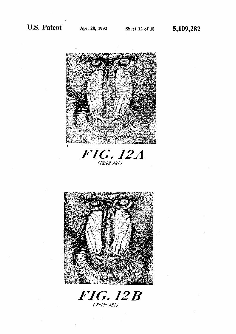
6 FIGS. 12A and 12B depict another moderate resolu
tion (512X512) image processed by two different conventional halftoning methods; Subsequently, for each block. the processor recalcu
lates what the average would be if the value of the preselected pixel position in the halftone image was the other extreme pixel value, and the corresponding error value in the error matrix was recalculated accordingly.
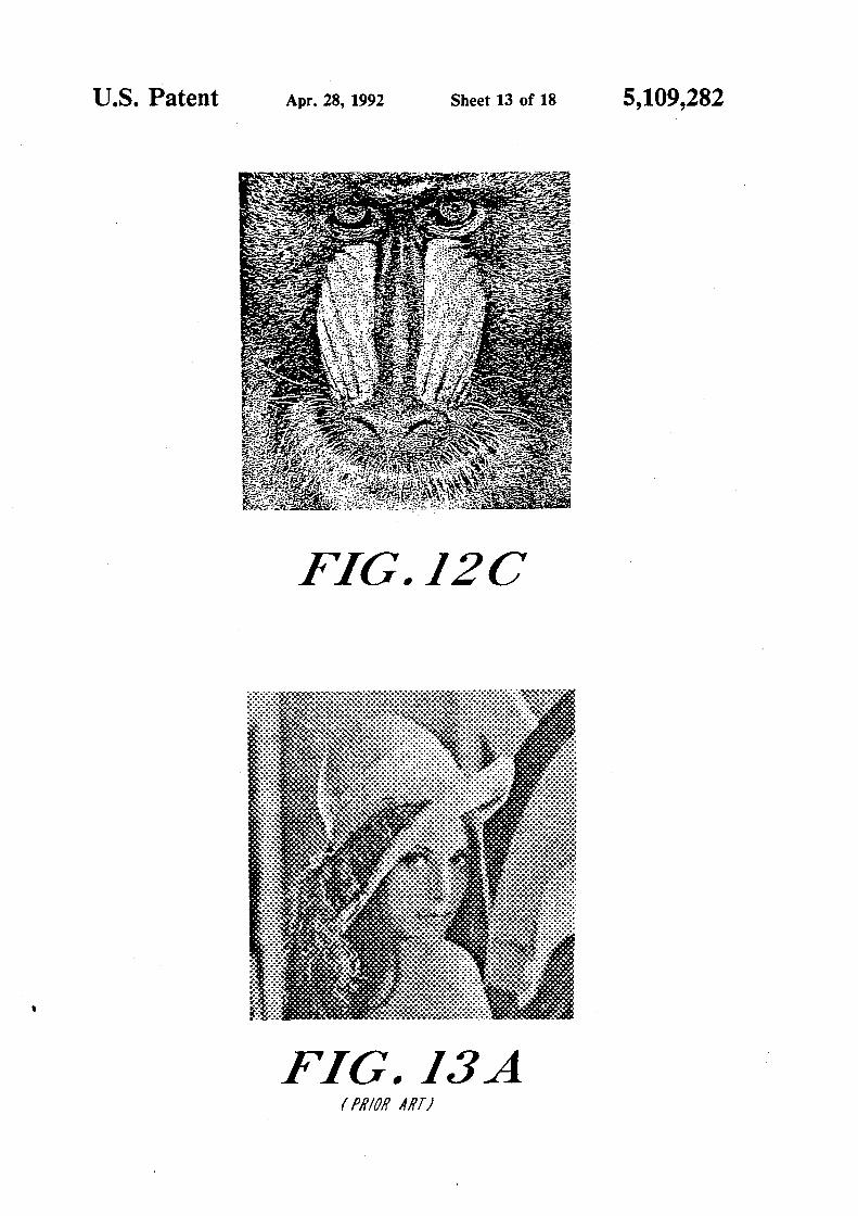
FIG. 12C depicts the image shown in FIGS. 12A and 5 128, processed by the pyramidal error convergence
method of the invention;
Thirdly, for each block. if the recalculated error average is less than the first calculated error average, the processor changes the value of the preselected pixel position in the halftone image to the other extreme pixel value.
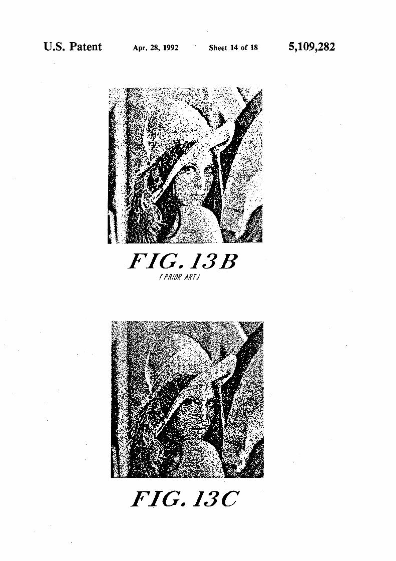
FIGS. 13A and 138 depict another image processed by two different conventional halftoning methods;
FIG. 13C depicts the image shown in FIGS. 13A and 10 138, processed by the pyramidal error convergence
method of the invention;
The invention will next be described in connection with certain illustrated embodiments; however, it
15 should be clear to those skilled in the art that various modifications, additions and subtractions can be made without departing from the spirit or scope of the claims.
BRIEF DESCRIPTION OF THE DRAWINGS . 20
For a fuller understanding of the nature and obJects of the invention, reference should be made to the following detailed description and the accompanying drawings, in which:
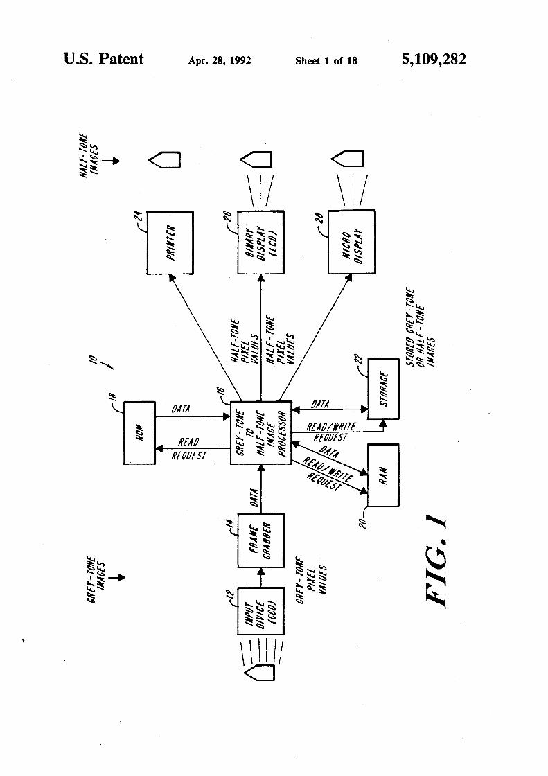
FIG. 1 i~ an electrical block diagram of an image 25 processing system constructed in accord with the in-vent ion:
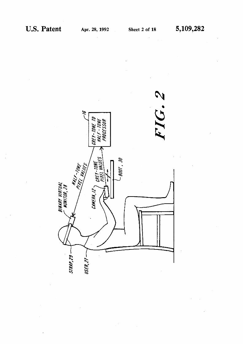
FIG. 2 is a schematic diagram depicting a visual aid embodiment of the invention;
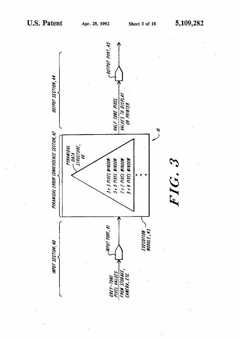
FIG. 3 is a schematic diagram showing the pyramidal 30 image process executed by the image processing module of FIG. 1, and the pyramidal data structure generated by the image processing module;
FIG. 4 is a flow chart depicting processing steps executed in accordance with the invention for convert- 35 ing a continuous grey tone input image into a high resolution halftone output image;
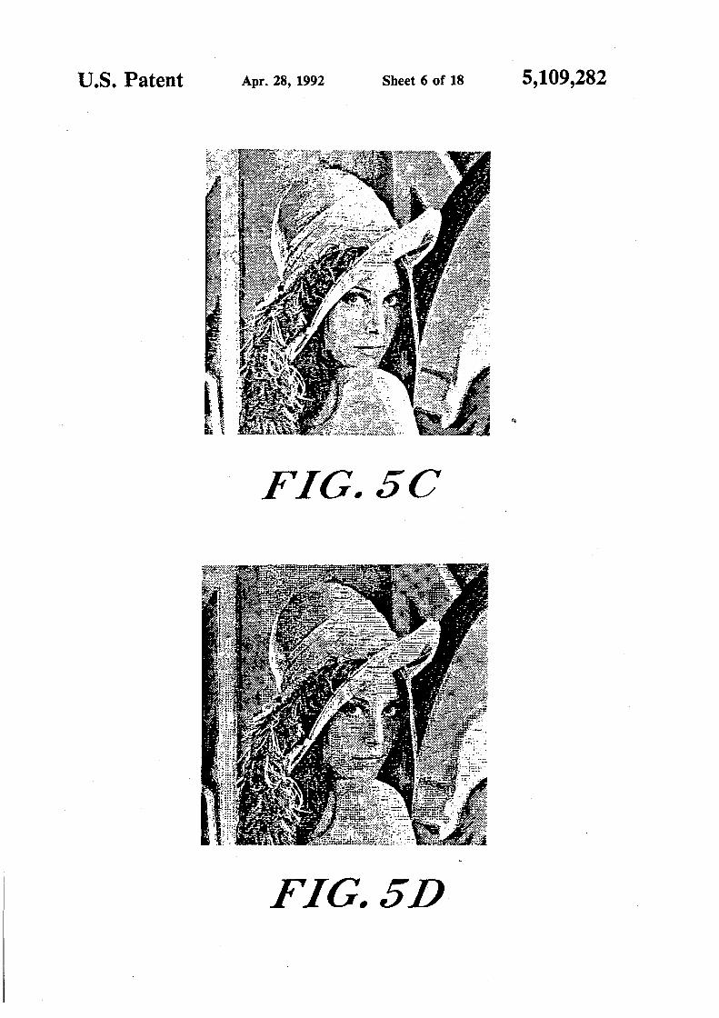
FIGS. SA-SE depict intermediate and final halftone images generated from a continuous grey tone input image in accordance with the method of FIG. 4; 40
FIG. SF depicts a halftone output image generated by a conventional halftoning method, from an input image identical to that utilized for FIGS. SA-SE;
FIG. 6 is a schematic diagram depicting pixel positions tested for possible change of binary assignment in 45
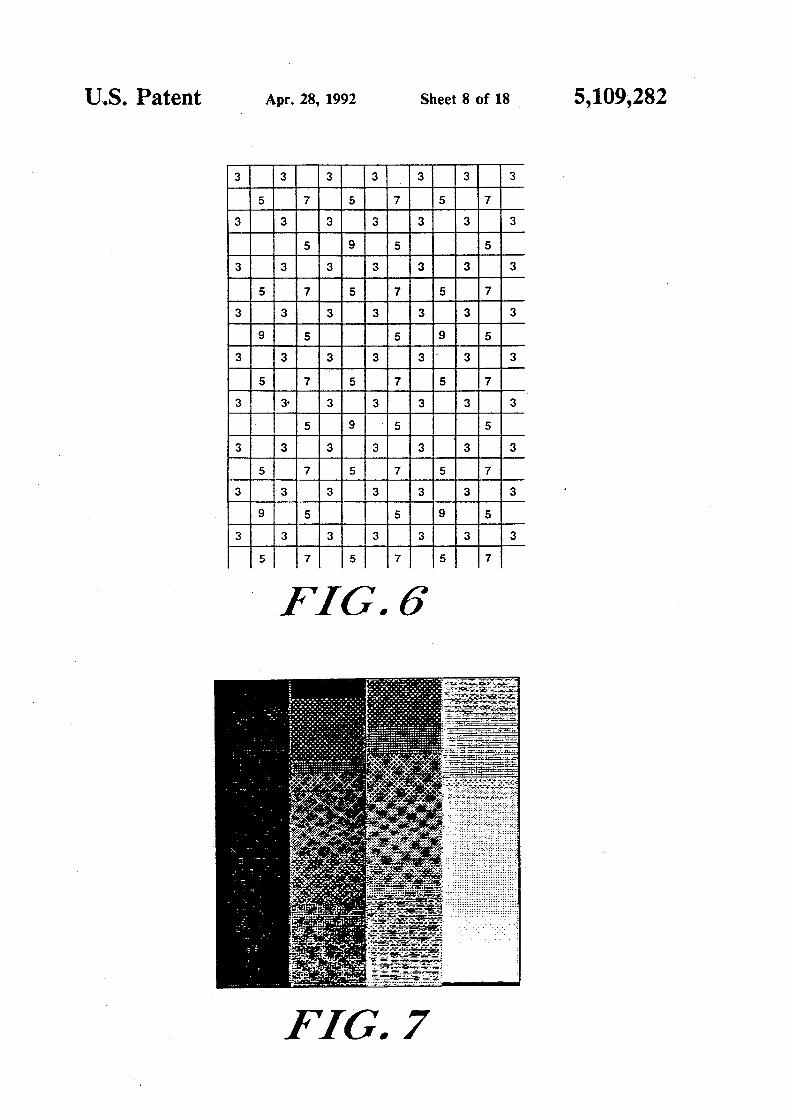
accord with the method of FIG. 4; FIG. 7 depicts the results of halftoning a linear grey
tone wedge in accordance with the method of FIG. 4; FIG. 8 is a schematic diagram depicting pixel posi-
50 tions tested for possible change of binary assignment in accordance with a clustered dot practice of the invention;
FIG. 9 depicts the results of halftoning a linear grey tone wedge in accordance with the clustered dots em- 55 bodiment of the invention, utilizing the same error threshold values utilized in FIG. 7, but with the test positions indicated in FIG. 8;
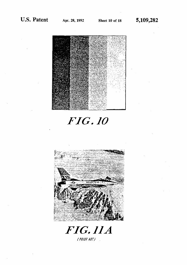
FIG. 10 depicts the results of halftoning a linear grey tone wedge in accord with another practice of the in- 60 vention, utilizing the test pixel positions indicated in FIG. 8;
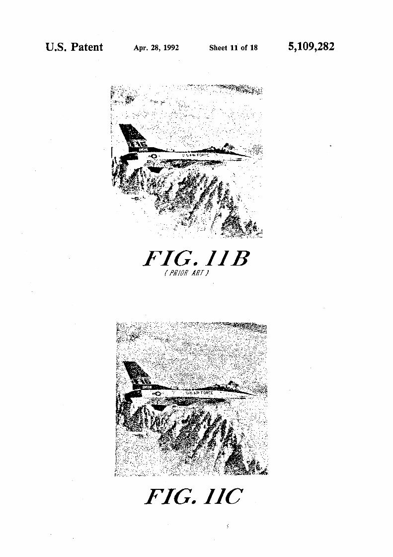
FIGS. llA and llB depict moderate resolution (5 12 x S 12) images generated by two different conven-tional halftoning methods; 65
FIG. llC depicts the image shown in FIGS. llA and llB, processed by the pyramidal error convergence method of the invention;
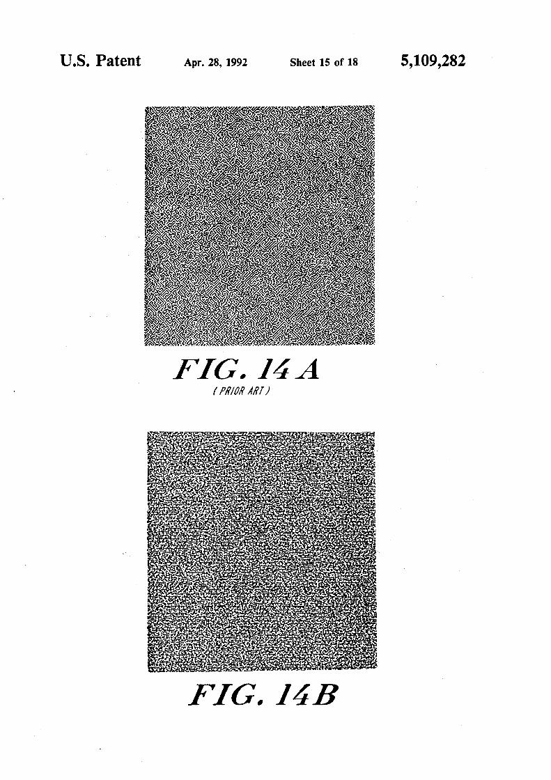
FIG. 14A depicts a sample image of uniform grey level, halftoned by the conventional error propagation method;
FIG. 148 depicts a sample image like that shown in FIG. 14A, halftoned in accordance with the invention;
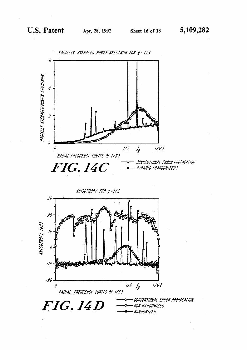
FIG. 14C is a graph indicating radial spectra obtained from 10 samples each of the images illustrated in FIGS. 14A and 148, using the conventional error propagation method, and the randomized pyramidal method of the invention, respectively;
FIG. 14D is a graph comparing anisotropy for the pyramidal error convergence method of the invention (randomized and nonrandomized), and the conventional error propagation method, respectively;
FIG. 1SA depicts a sample image of another uniform grey level, halftoned by the conventional error propagation method;
FIG. lSB depicts a sample image like that depicted in FIG. 1SA, halftoned in accordance with the invention;
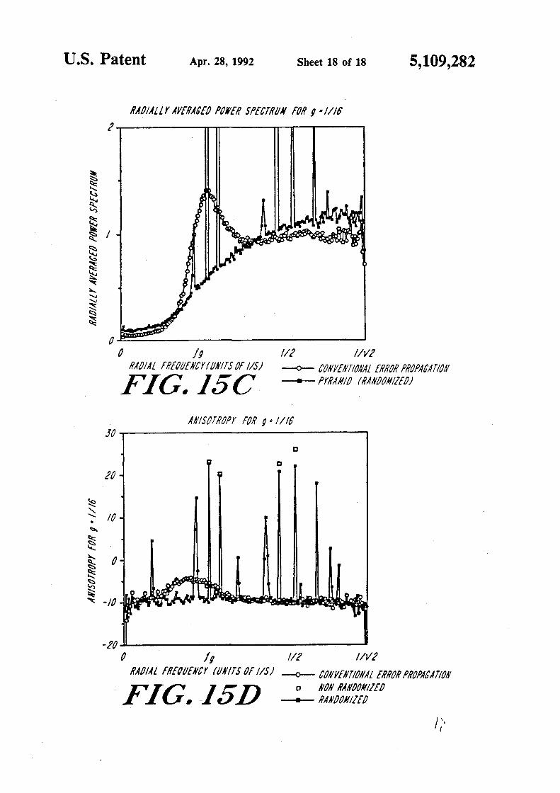
FIG. 1SC is a graph indicating radial spectra obtained from 10 samples each of the images illustrated in FIGS. lSA and 1SB, using the conventional error propagation method. and the randomized pyramidal method of the invention. respectively; and
FIG. lSD is a graph comparing anisotropy for the pyramidal error convergence method of the invention (randomized and nonrandomized), and the conventional error propagation method, respectively.
DESCRIPTION OF ILLUSTRATED EMBODIMENTS
System Structure
FIG. 1 is a block diagram of an image processing system 10 constructed in accordance with the invention. The system converts multi-value grey tone images into half-tone images that can be displayed or printed by limited-resolution monochrome monitors or printers, without the visual artifacts associated with conventional halftone imaging systems.
More particularly, the system 10 utilizes an image processor 16 that receives input signals representative of grey tone images, and executes an image conversion process in accord with the invention (discussed below in connection with FIG. 4) to generate a halftone image having high spatial resolution. The image conversion is implemented by processor 16 under the control of instructions stored in read-only memory (ROM) 18 or an equivalent permanent information storage device. Data utilized in the conversion process or generated by the process can be stored in, and retrieved from, a random access memory (RAM) device 20.
In one embodiment of the invention, image processing module 16 contains a general-purpose microcomputer processor, such as the Intel Corporation 80386. Alternatively, image processing module 16 can include a processor constructed specifically for rapid execution
7 5,109,282
8 era 12 generates a grey-tone image. and transmits pixel values representative of the image to processor 16. The processor converts the grey tone image data into pixel values representative of a magnified halftone image of
of the image conversion process of the invention. This special-purpose embodiment of image processing module 16 can utilize a neural network or other highly-parallel multiprocessor architecture, as discussed in greater detail hereinafter. 5 high spatial resolution, in accord with the method de
scribed hereinafter. The processor then relays the pixel values of the magnified halftone image to binary display 28, for viewing by the user.
As indicated in FIG. 1, the halftone output images generated by the processor 16 can be transmitted to a printer 24 or a conventional binary monitor 26 for printing or displaying the halftone image. Because the invention enables visually enhanced rendition of halftone to images on low-cost, moderate-resolution monitors and printers, display 26 can be a conventional liquid crystal display (LCD) or plasma display device, and printer 24 can be a conventional laser printer or ink jet printer having a resolution of 300 dots per inch (dpi).
The original multi-value grey tone image can be generated by a conventional input device 12, which can include a vidicon camera, CCD array, or other conventional imaging element for collecting light from an object 11 to form an image of the object. In the illustrated 20 embodiment, the output of imaging device 12 is transmitted to a conventional frame grabber 14, which relays image-representative digital signals to image processor
This embodiment of the invention thus provides a compact, portable closed-circuit viewing system for vision impaired individuals, which affords a significantly larger visual field than that provided by conventional miniature, portable viewing systems. In particular, the visual field of the illustrated system utilizing a
15 Private Eye display is approximately twice that afforded by a conventional system utilizing a Sony Watchman® or other miniature television screen. The size of visual field provided by the Private Eye or other
16 on a frame-by-frame basis. The output of the frame grabber 14 is a series of digital picture element (pixel) 25 values representative of a grey-tone image.
Alternatively, the input image can be obtained from a storage module 22, which may include conventional magnetic disks, optical disks, or other elements for storing digital data representative of images. The stored 30 images can include grey tone images generated by the input module 12, grey tone images generated remotely by other input devices and transferred to storage, or halftone images generated by the image processor 16. Those skilled in the art will recognize that because the 35 input to processor 16 can include images stored in and transferred from a storage device, the invention can be
virtual monitor device can be further expanded by twenty to fifty percent through modification of the virtual monitor. A virtual monitor is also lighter and more compact than conventional miniature television screens.
Additionally, the head-mounted display system de-picted in FIG. 2 enhances the user's ability to navigate across text and select text regions to be magnified. Low vision patients with substantially equal vision in both eyes, as well as patients having only one useful eye, can position the display so that the enlarged material appears in a region of the visual field corresponding naturally to the area being sought with the camera.
A further significant benefit provided by the illustrated embodiment is the extremely high contrast provided by a virtual monitor such as the Private Eye. This contrast level greatly exceeds that afforded by conven-tional miniature television screens.
practiced without input device 12 and frame grabber 14. System Operation-Overview Moreover, it will be appreciated that a modem or other conventional data transmission apparatus can be em- 40 Having described image processing systems utilizing ployed to relay grey tone image data to the image pro- image processor 16, further discussion of the operation cessor 16. of image processor 16 is now in order. with reference to
In the embodiment depicted in FIG. 1. the halftone FIGS. 3 and 4. As depicted in FIG. 3, the image proces-images generated by processor 16 can also be transmit- sor 16 incorporates an input section 40 having a conven-ted to a micro-display device 28. One such micro-dis- 45 tiona! input port 41 for receiving grey tone pixel values play is the Private Eye manufactured by Reflection from an imaging device or from storage; an execution Technology of Waltham, Mass. The Private Eye, re- module 43 having an error convergence section 42 that ferred to herein as a "virtual monitor," is worn over a executes a pyramidal, multi-resolution error conver-user's eye. A temporally-modulated light beam or gence process described hereinafter to convert the grey "spot" is rapidly scanned across the visual field of the 50 tone values to halftone values with high spatial resolu-eye. so that an image is formed on the retina of the eye. tion; and an output section 44 including an output port The modulation of the beam and the content of the 45 for relaying the halftone pixel values to a conven-image are controlled by information-representative tiona) display or printer. input signals transmitted to the device. The virtual mon- . As indicated in FIG. 3, the execution module 43 gen-itor thus utilizes the persistence characteristic of the 55 erates . a pyramidal data structure 46. The pyramidal human visual system to form an image that is visible structure incorporates successively larger data levels, only to the wearer. By utilizing a virtual monitor or each characterized by a selected region or "window" of other binary micro-display, the image processing as- image pixels (3 X 3, 5 X 5, 7 X 7, 9 X 9, etc.) that are pro-peels of the invention can be practiced in the image cessed in accordance with the method steps depicted in enhancement/magnification system depicted in FIG. 2. 60 FIG. 4.
Referring now to FIG. 2, the illustrated system 10 FIG. 4 shows a method for determining the binary enables individuals with low vision deficiencies to read assignment-for example, black or white-of each pixel standard-font printed matter, by providing image mag- of the output image, based on the grey-tone value of nification and contrast enhancement. The user 27 wears corresponding pixels of the input image. The method a virtual monitor or other miniature binary display 28 65 depicted in FIG. 4 is referred to herein as an error con-that is affixed to the user's head by a strap 29. The user vergence method, because the binary value assignment can then move a conventional camera 12 across the for a given pixel is determined in response to error print lines of a book or other written material 30. Cam- values associated with all neighboring pixels.

9 5,109,282
In particular, the error convergence method of FIG. 4 is a progressive coding scheme ptilizing a pyramidal structure based on errors generated by the binary assignment at each pixel. At each successive level of the pyramid, larger regions of pixels are tested for a possible S change of the binary assignment, in response to progressively larger regions of evaluation of local errors. As discussed below, the utilization of Jess than fifty percent overlapping pixel "neighborhoods" in the error conver-gence process enables parallel processing. 10
The results of the method of FIG. 4 are best explained with reference to FIGS. SA-SD, which depict images corresponding to the progressive development of a halftone image at the various levels of the pyramidal error convergence method of the invention. Refer- 15 ring to FIG. 4, in the first level of the pyramid, the execution module 43 (FIG. 3) thresholds the original grey tone image l(i,j) on a pixel by pixel basis (step 110) to generate a binary image B(i,j). In one embodiment,
20 the thresholding is defined as follows:
Eq.(l)
B(l,J) = 0 if /{i.J) ;;;; 127
10 is changed, or inverted. If change would result in a larger average error, the pixel value is not inverted.
Not every pixel will be tested. Instead, certain pixels are selected for testing, as indicated in FIG. 6, which depicts the pixel positions tested at each level of the process pyramid. At the 3 X 3 level of the process pyramid, the execution module tests every other pixel on every other line, as indicated by the positions marked by the numeral "3" in FIG. 6.
The test pixel positions indicated in FIG. 6 represent alternating diagonal horizontal-vertical patterns of selected pixels. These patterns have been found to provide good output image quality. Because the test pixel' positions form diagonal arrays, for input images having uniform grey levels requiring a change of only the test pixels from their background, the pattern will have a visually more acceptable diagonal screen pattern.
This test pixel selection scheme avoids overlapping of the windows from which the errors are calculated with any other point that may have been changed at a given level of the pyramid. This independence permits com-
. ( 255 if /(i.j) > 127
FIG. SA shows the binary image resulting from this thresholding at the first level of the pyramid. The thresholded image is characterized by low spatial resolu-
25 pletely parallel operation, because a pixel ·being changed will not affect the averaged error in any other neighboring point being considered in the image. The illustrated selection of pixels thus enables the use of high-speed, parallel computing architectures for halftone image generation.
~. ~ The execution module 43 (FIG. 3) then compares the
binary image with the original image (step 112) to obtain an error array E(i,j), except for E=O, where E(i,j) is the difference between the pixel values of the original input grey tone image and the binary image, as ex- 35 pressed in Equation 2:
E(i.J)= B{i.J)-I{i.J) Eq. (2)
The sign of the error E(i,j) is thus representative of the pixel values in the binary image B(i,j), except in the case 40 of E(i,j)=O, which is ambiguous.
In the second level of the pyramid, the execution module 43 (FIG. 3) addresses windows of 3 X 3 pixels. The signed error array, E{i,j), is convolved (step 120) with a 3 X 3 matrix, x(3), to yield a weighted average 45 error of order 3, E<3l(i_,j), as follows:
if.3Jii.JI=E(i.J) • xf3l Eq. (3A)
where • is the convolution operator and
At this level in the image conversion process, following calculation and correction of errors over windows of 3 X 3 pixels, the corresponding image resembles that depicted -in FIG. SB. Next, the error array is updated (step 124) for every change of a pixel (from black to white, or white to black) according to the following expression:
E(' ~ _ ( E - 2SS if white - black '·1 - E + 255 if black - white
Eq. (4)
Thus, the original error array is modified wherever a decision is made to change the polarity of a pixel. The execution module then utilizes this modified error array to calculate the next level of the pyramid, in which 5 X 5 ·
SO windows are utilized. I I
"""i'2 """i'2
xf3) = + I T
I I """i'2 """i'2
I """i'2
I """i'2
I """i'2
Eq. (38) The 5 X 5 level of the pyramid is processed in a man
ner similar to that utilized in calculating the 3 X 3 level, by obtaining, for every point in the array, a weighted
55 average error over a 5 X 5 mask. This is expressed by the following equation:
The sum of the weight of the terms in x<3) is equal to £1.5l(i.J)=E(i.J) • .xl5> Eq. (S) unity. The weight of the terms can be selected from The actual calculation of the average is performed by various alternatives, each providing different weight 60 t · 1 · ( t l30) th pd t d y d
. . . . . wtce convo vmg s ep e u a e error arra tstnbuuons between central and surroundmg pomts. E . . . .
3 . . '(3)
The execution module next compares the averaged {t,J~ ~tth ~ umform 3 X averagmg. ~atnx x . -a error with the original error at selected pixel positions matnx m whtch all terms equal 1/9. Thts ts summanzed (step 122) to determine whether a change of the binary by Equation 6: assignment of each test pixel (from black to white, or 65 white to black) will result in a smaller average error over the 3 X 3 window. If a change to a tested pixel would result in a smaller average error, the pixel value
ECSl(ij)=E(ij) • x13) • x•(3) Eq (6)
The result of these two convolutions is equivalent to one convolution with a 5 X 5 matrix x(S), as follows:
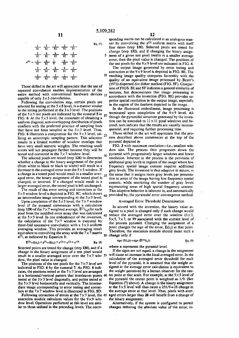
I 8"1
11
2 3 2 8"1 8"1 8"1
I 8"1
5,109,282 12
Eq. (7)
sponding matrix can be calculated in an analogous manner by convolving the x<3l uniform matrix with itself four times (step 130). Selected pixels are tested for change (step 132), and if changing the binary assign-
2 8"1
.. 6 4 8"1 8"1 8"1
6 8"1
I 9
6 8"1
_2_ 81
_3_ 81
s ment of a given test pixel results in a smaller average error, then the pixel value is changed. The positions of the test pixels for the 9X9level are indicated in FIG. 6.
I 8"1
4 8"1
2 8"1
6 8"1
3 8"1
4 8"1
2 8"1
2 _1_ 8"1 81
The output image generated by error testing and correction at the 9 X 9 level is depicted in FIG. SE. The
10 resulting image quality compares favorably with the quality of an equivalent image processed by Bayer's (1973) dispersed dot dither method (FIG. SF). Compar-
Those skilled in the art will appreciate that the use of ison of FIGS. SE and SF indicates a general similarity of repeated convolution enables implementation of the entire method with conventional hardware devices 15 textures, but demonstrates that image processing in capable of only 3 x 3 convolutions. accordance with the invention (FIG. SE) provides su-
Following the convolution step, certain pixels are perior spatial resolution in the output image, especially selected for testing at the 5 X S level, in a manner similar in the reg~on of the feather~ depict~d in the imag~. . to the testing performed at the 3 x 3 level. The positions In. the Illustrated embo~1ment, Image processmg IS of the 5 X 5 test pixels are indicated by the numeral S in termmated upon completiOn of the 9 X 9 level. AI-FIG. 6. At the 5 x 5 level, the constraint of obtaining a
20 though the pyramidal structure generated by the inven-
uniform diagonal, non-overlapping distribution of pixels tion can be extended to 11 X 11 pixel windows and be-conflicts with the preferred practice of sampling lines yond, tests indicate that the results are visually inconse-that have not been sampled at the 3 x 3 level. Thus, quential, and requiring further processing time. . FIG. 6 illustrates a compromise for the 5 x 5 level, uti- 25 Those s~illed in the art will appreciate that the pro-lizing an anisotropic sampling pattern. This selection cess descnbed above commences at the top of the results in a limited number of window overlaps that pyramid depicted in have very small numeric weights. The resulting small FIG. 3 with maximum resolution-i.e., smallest win-errors will not propagate further because they will be dow size. The process then progresses down the tested and corrected in the 7 X 7 window level. 30 pyramid with progressively larger windows and lower
The selected pixels are tested (step 126) to determine resolution. Inherent in the process is the provision of whether a change in the binary assignment of the pixel additional gray levels in regions of the image where low (from white to black or black to white) will result in a frequency spatial image content requires additional decrease in the averaged error over the 5 X 5 window. If grey levels. The invention inhus adaptive in nature, in a change in a test~d pixel ~ould result in a smaller_ ave:- 35 the sense that it assigns more gray levels per presenta-aged error, t~e bmary asstgnment of the tested ptx~l IS tion to areas of the image having low frequency spatial changed, or mverted. If a chang~d ~ould result m a content, while restricting the number of gray levels larger averaged er:or, the test~d p1xel ts left u~changed. representing areas of high spatial frequency content.
The ~esult of tht~ erro: testt.ng and correct~on at the This adaptive behavior is inherent in, and automatically 5 x_5 wmdo~ le~el1s depicted m F_IG. SC, which shows 40 provided by, the pyramidal error convergence method. an mtermedtate tmage correspondmg to the 5 X 5 level.
Upon completion of the 5 X 5 level, the 7 X 7 window level of the pyramid commences with a calculation (step 128) of the 7 X 7 weighted average, E(7J(iJ) for each pixel from the modified error array that was calculated at the 5 X 5 level. In one embodiment of the invention, 45
the calculation of the 7 X 7 window is executed by three-fold successive convolution with a 3 X 3 uniform averaging window. This provides an averaging result equivalent to convolving the array with the 7 X 7 matrix x<7l, as indicated by Equation 8: 50
E:<'l=E(i.il • x(7)=E(iJ) • ,.·(3) • ,.·(3) • ,.·(3) Eq. (8)
Selected points are tested for change (step 130), and if a change in the binary assignment of a test pixel would result in a smaller averaged error over the 7 X 7 win- 55 dow, the pixel value is changed.
The positions of the test pixels for the 7 X 7 level are indicated in FIG. 6 by the numeral 7. As FIG. 6 indicates, the positions tested at the 7 X 7 level are arranged in a horizontal/vertical pattern that interleaves points 60 tested at the 3X3level diagonally, and points tested at the 5 X 5 level horizontally and vertically. The intermediate image corresponding to error testing and correction at the 7X7 window level is illustrated in FIG. SD.
Following correction of errors at the 7 X 7 level, the 65 execution module calculates values for the 9 X 9 window level. Operations performed at this level are similar to those utilized in the preceding levels. The corre-
Averaged Error Threshold Determination
In accord with the invention, the binary value assigned to a pixel is changed only if such change would reduce the averaged error over the window (3 X 3, 5X5, 7x7, or 99 associated with the current level of the process pyramid. Changing the assignment of a point changes the sign of the error, E(i,j) at that point. Therefore, the execution module should make such a change only if
sign (E(i.j))=sign (ECn)(i.j)) ~.(9)
where n represents the pyramid level. If the signs are not equal, a change in the assignment
will cause an increase in the local averaged error. In the calculation of the averaged error threshold for each level of the pyramid, it is assumed that the weight assigned in the average error calculation is equivalent to the weight perceived by a human observer for the center point at that scale. For example, at the 5 X 5 level of the pyramid the center point is weighted as 1/9. (See Equation (7) above). A change in the binary assignment at the 5x5 level will thus cause a 255/9=28 change in the average error at that level. Thus, pixels with averaged errors larger than 28 will benefit from a change of the binary assignment.
Alternatively, if the system is configured to permit changes reducing the absolute value of the error, in-
13 5,109,282
14 eluding cases in which such changes invert the sign of the averaged error, then pixels with averaged error larger then 14 can be changed.
Applying these criteria to the method discussed above, tests have been performed using linear grey tone 5 wedges as input images, to evaluate the accuracy with which the binary output images represent the input grey levels. These tests have demonstrated that the above criteria result in an unequal representation of the grey levels of a linear grey tone wedge. In addition, the 10 number of grey levels represented was less than expected. These effects result from arbitrary selection of weight for the x(3) matrix, and from non-ideal placing of the points tested at 5 X 5 level.
In order to improve the results of the process. error 15 correction thresholds can be empirically determined for each level of the pyramid, by utilizing values that divide each previous section of the grey scale wedge into two nearly equal sub-sections. Table I compares empirically determined error thresholds with threshold values cal- 20 culated in accordance with the above-listed criteria.
TABLE I
rather than dispersed dots, where possible. The resulting patterns represent a compromise between dispersed dot and clustered dot patterns, with greater clustering of the dots occurring toward intermediate levels of grey tones.
This effect is depicted in FIG. 9, which shows the results of halftone processing a linear grey tone wedge with the clustered dots pattern, using error thresholds of the same values as those utilized in connection with FIG. 7. The tested pixel positions are those indicated in FIG. 8.
Those skilled in the art will appreciate that ink spread characteristics and differences between the size of a printed dot and a non-printed dot may result in printed grey levels thai are not linearly related to the number of black dots. This is discussed in Stevenson et al., "Binary Display of Hexagonally Sampled Continuous-Tone Images", JOSA A, Vol. 2, pp. 1009-1013, 1985. Thus, an optimal, accurate assignment of error thresholds may be printer-dependent and paper-dependent, and can be obtained only be extensive calibration. However, the empirical values noted in Table I provide a good first
Error threshold> u'ed t0 determine whether a pixel binary approximation from which such assignments can be a.signment should be changed: ______ ___::..._ _____ .......:'--------
25 determined.
pyramtJ level 3 x ~ 5 X ~ 7 X 7 9 · X 9 calculated values 43_8{, 14-.lB 9_18 7_14 Position Noise Dithering: The pyramidal error con-empirical \'alue 64 36 to 3 vergence methods described above combine high reso-
FIG. 7 depicts a linear grey tone wedge halftoned with the empirically determined error threshold values 30 shown in Table I. These error threshold values provide a more even distribution of values along the wedge, and enhance the number of distinguishable grey levels. In
lution with large dynamic range, and provide visually pleasing diagonal textures in the output halftone image. The dispersed dot embodiment of the invention provides diagonal textures similar to those generated by certain prior art methods, but with higher spatial resolution. See, for example, Bayer's dispersed dot dither technique. The enhanced spatial resolution provided by FIG. 7, 32 grey levels are discernable.
35 the invention is demonstrated by a comparison of FIG. Clustered Dots and Position Dither
In addition to the basic method discussed above in connection with FIG. 4, other embodiments of the invention can incorporate clustered dot methods and position dithering, as described below. Clustered dots 40 can be utilized to enhance printing reproducibility. Position dithering. in turn, can be employed for reducing contouring and anisotropy of the mixture, and to furnish desirable blue noise characteristics.
Clustered Dots: The selection of test pixels indicated 45 in FIG. 6 results in dispersed doCpatterns, as is evident from FIG. SE and FIG. 7. Unfortunately, dispersed dot patterns frequently do not reproduce well in print media, because of unreliable reproduction and placement of single dots. Accordingly, clustered dot patterns have SO been developed to improve the quality of reproduction by laser printers and other moderate-resolution print devices. The pyramidal error convergence method of the invention is readily modified to accommodate clustered dot patterns, further enhancing print reproduc- SS tion. The only modification required to implement this is a different selection of points to be tested at each level of the process pyramid, as indicated in FIG. 8.
FIG. 8 depicts pixel positions to be tested at each process level in a clustered dots embodiment of the 60 invention. The shaded areas indicate the windows over which error values are calculated for the 3 X 3 level (to left) and 5 X 5 level (bottom). This pattern diverges from the pattern depicted in FIG. 6, beginning with the 5 X 5 level of the process pyramid. In particular, points 65 at the 5 x 5 level and succeeding levels are situated adjacent to points already tested at eailier levels of the process pyramid. This adjacency provides clustered
SE with FIG. SF. The resolution advantage over conventional dither techniques, and the multiplicity of grey levels discernable in the halftone output-e.g., thirty-two grey levels-are significant benefits of the dispersed dot practice of the invention.
The halftone output of the image processor can be further enhanced, moreover, by eliminating visible false contour lines. These artifacts, which are similar to those evident in images processed by Bayer's dither method, are discernable because of the visibility of texture changes in areas of low grey level gradient, as in FIG. SE.
Additional improvements in appearance can be attained by enhancing the texture within areas of uniform grey level. Research by Ulichney demonstrates that halftone patterns of uniform grey levels having "blue" noise characteristics and reduced anisotropy are much more acceptable and visually pleasing than are patterns lacking these characteristics.
One embodiment of the invention provides improved blue noise and isotropy characteristics, while simultaneously reducing false contouring, by introducing pseudo-random variations or "noise" in the selection of points tested at each level of the process pyramid. Instead of testing points in accord with the orderly grids depicted in FIG. 6 or FIG. 8, the execution modult! in this embodiment of the invention pseudo-randomly "shifts" the selection to one of the eight neighborir.g pixels, for approximately half the pixels in the image field. The decision as to which pixel will be tested and modified is established in accord with known random variable processes. This random selection need not be
5,109,282 15
re-calculated for each image; it can be selected once and then fixed and used for every image.
In accord with this embodiment of the invention, horizontal and vertical shifts are determined independently. In one embodiment, the probability of shift of a 5 tested central point to any of the neighboring positions is designated by a matrix P, where
I 2 I Eq. (10)
6(j'"' 15 6(j'"' 10
P=+ 8 I 15 15
I 2 I 6(j'"' 15 6(j'"'
16 this method, however, is inherently slow. FIG. llC presents the same image processed by a pyramidal error convergence method in accord with the invention. As FIG. llC demonstrates, the invention provides higher spatial resolution with smooth transitions in regions of shallow gradients. Although the textures are slightly Jess pleasing then the textures obtained with the error propagation method, the invention provides superior spatial resolution and enables faster implementation.
The results of this position noise dithering variation are exemplified by FIG. 10. In particular, FIG. 10 shows a linear grey tone wedge halftoned by the clustered dot position-dithered method, using the same test pixel selections as those employed in FIG. 9-i.e., the 20 positions indicated in FIG. 8. Comparing FIG. 10 to FIG. 9, it will be seen that false contours are significantly reduced, and that only a few such contours are visible, at the very dark and very bright ends of the
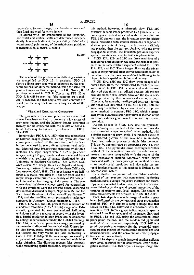
FIGS. 12A, 12B, and 12C are three renditions of a baboon race, processed by the same methods (and presented in the same relative sequence) utilized for FIGS. llA, liB, and llC. These images illustrate the advantages ofthe pyramidal error convergence method of the
15 invention over the two conventional halftoning tech-
wedge. 25
· Visual and Quantitative Comparison
The pyramidal error convergence methods described above have been utilized to process a wide range of grey tone images, and the halftone images generated 30 thereby can be compared with the results of conventional halftoning techniques, by reference to FIGS. llA-lSD.
In particular, FIGS. llA-lSD relate to a comparison of halftone images generated by the pyramidal error 35 convergence method of the invention, and halftone images generated by two different conventional methods. Identical input images were processed by all three methods. The input images were 512X512 grey tone images having 256 grey levels, and were selected from 40 a widely used package of images distributed by the University of Southern California. (See Weber, USC SIP/ Reoort 101, Image Data Base Signal and Image Processing Institute, University of Southern California, Los Angeles, Calif., 1988). The input images were half- 45 toned at a spatial resolution of I dot per pixel, and the output images were printed at a density of 150 dots per inch, to enable clear imaging of dot patterns. The two conventional halftone methods tested for comparison with the invention were the ordered dither, dispersed 50 dots method discussed in Bayer, "Optimum Method for Two Level Rendition of Continuous-Tone Pictures," 1973; and the modified error propagation technique addressed in Ulichney, "Digital Halftoning," 1987.
FIGS. llA, llB, and llC present three renditions of 55 a moderate resolution (512X512 dots) image of an F-16 aircraft, generated by two conventional halftoning techniques and by a method in accord with the invention. Spatial resolution in each image can be compared by noting the serial number under the F-16 tail marking. 60 FIG.llA, in particular, presents an image processed by a conventional dispersed dot method with 33 grey levels. See Bayer, supra. Spatial resolution is acceptable, but textures are very visible and false contouring is evident. FIG. llB depicts the same image processed by 65 a conventional error propagation method with blue noise dithering. The dithering reduces false contours while maintaining spatial resolution. Implementation of
niques, in both spatial resolution and texture. FIGS. 13A, 13B, and 13C show three images of a
human face. Here, the textures used to render the skin are critical. In FIG. 13A, a simulated optical-screen clustered dots dither was utilized because this method provides smooth skin texture; however, the spatial resolution provided by this conventional method is poor. (Compare, for example, the dispersed dots result for the same image, as illustrated in FIG. SE.) In FIG. 13B, the same image is halftoned by a conventional error propagation method. In contrast, FIG. 13C, which is generated by the pyramidal error convergence method of the invention, exhibits good skin texture and high spatial resolution.
As can be seen in FIGS. 11A-13C, the pyramidal error convergence method of the invention provides spatial resolution superior to both other methods, with a similar number of grey levels. The random nature of the dithered pattern of the invention substantially blends and reduces previously visible false contours. This can be demonstrated by comparing FIG. SE with FIG. 13C. The pyramidal error convergence/dither method of the invention thus also provides smooth texture transitions comparable with the results of the error propagation method. Moreover, while images processed with the error propagation method demonstrate good spatial resolution and blue noise texture, rapid implementation of this method is limited by its inherent serial nature.
In a further comparison of the dither variation method of the invention with conventional halftoning methods, radial average frequency spectrum and anisot-ropy were evaluated to determine the effect of position noise dithering on the spatial spectral properties of the textures of uniform grey level images. The results of these measurements are depicted in FIGS. 14A-1SD.
FIG. 14A depicts a sample image of uniform grey level, halftoned by the conventional error propagation method. FIG. 14B depicts a sample image like that shown in FIG. 14A, halftoned in accordance with the invention. FIG. 14C is a graph indicating radial spectra obtained from 10 samples each of the images illustrated in FIGS. 14A and 14B, using the conventional error propagation method, and the randomized pyramidal method of the invention, respectively. FIG. 14D is a graph comparing anisotropy for the pyramidal error convergence method of the invention (randomized and nonrandomized), and the conventional error propagation method, respectively.
FIG. 1SA depicts a sample image of another uniform grey level, halftoned by the conventional error propagation method. FIG. 1SB depicts a sample image like

,
17 5,109,282
18 entations. The anisotropy represented by the peaks is not immediately discernable to human observers.
Implementation With Parallel Architectures
Based on the pixel selection criteria discussed above, multi-resolution pyramidal error convergence methods in accord with the invention can be implemented in a multiprocessor computing system or other parallel processing computer architecture. Preferably, the process-
that depicted in FIG. lSA, halftoned in accordance with the invention. FIG. lSC is a graph indicating radial spectra obtained from 10 samples each of the images illustrated in FIGS. lSA and 1SB, using the conventional error propagation method, and the randomized 5 pyramidal method of the invention, respectively. FIG. JSD is a graph comparing anisotropy for the pyramidal error convergence method of the invention (randomized and nonrandomized), and the conventional error propagation method, respectively.
FIGS. 14A, 14B, 14C and 140, in particular, demonstrate certain characteristics of sample images of uniform grey level 85 (g= i). The sample image in FIG. l4A was generated by a conventional error propagation method, utilizing selected weight values in accord with I 5 the method recommended for a rectangular grid by Ulichney. The sample image in FIG. 14B, conversely, was generated by a pyramidal error convergence method in accord with the invention, utilizing random position dithering. Very little directional texture can be 20
discerned. Thus, comparison of FIGS. 14A and 14B demonstrate that the pyramidal error convergence method provides better performance than the conven-
10 ing element or elements should be capable of simultaneously executing 3 X 3 convolution operations for a complete 512 X 512 pixel image. Such processing devices are now available, and tests have demonstrated
tional error propagation method. 25 As noted above, FIG. 14C depicts radial spectra obtained from 10 samples each of the images illustrated
that relatively inexpensive hardware embodiments of the invention can perform the convolution operation in approximately 0.03 seconds. As discussed above, the invention utilizes iterative application of the 3 X 3 convolution step: once for the 3 X 3 level, twice for the 5 X 5 level, three times for the 7 X 7 level, and four times for the 9 X 9 level, for a total of ten iterations of the 3 ·X 3 convolution operation. These iterations determine the time required for calculating a 512 X 512 pixel image. Images larger than 512 X 512 can be divided into smaller overlapping segments that are processed and recombined in a known manner after removal of the overlapped edges. Those skilled in the art will appreciate that the overlapping areas are used in removing edge artifacts from each section. A significant advantage of the invention is that the randomization associated with position noise dithering, as described above, provides an invisible seam between segments.
It will thus be seen that the invention efficiently attains the objects set forth above, among those made apparent from the preceding description. In particular,
in FIGS. 14A and 14B. generated by conventional error propagation and by the pyramidal error convergence method of the invention, respectively. The spectra cor- 30 responding to the pyramidal method contain strong peaks at a few frequencies, but both spectra have the preferred characteristics of low frequency cut-off at the principal frequency (F8), sharp transitions, and relatively flat blue noise area.
FIG. 14D shows the anisotropy calculated for the pyramidal error convergence method (for both randomized and non-randomized variations) compared with the anisotropy of the error propagation sample. The ideal result would be flat anisotropy of - lOdB. 40 The randomized pyramidal method attains this level, except for a few spikes. In the error propagation method, however, anisotropy increases at the principal frequency to the OdB. The non-random version of the pyramidal error convergence method is presented to 45 illustrate the effect of randomization in reducing the anisotropy by 25dB or more across most frequencies.
35 the invention provides a multi-resolution error convergence method that attains significant advantages over conventional halftone methods. It provides superior spatial resolution and an enhanced dynamic range. The
FIGS. 15A, 1SB, 1SC and 1SD are similar to FIGS. 14A, 14B, 14C and 14D, respectively, except that the image is characterized by grey level 16 (g= 1/16). As so FIGS. 14C and 14D indicate, the error propagation method of the invention provides better anisotropy results. In this case, the spectral characteristics are very similar and close to the ideal for both methods.
As FIGS. 14C, 14D, JSC, and 1SD illustrate, the 55 spectra corresponding to the dithered patterns of the invention contain spikes at frequencies corresponding to the underlying ordered pixel selection patterns. However, ihe general characteristics of the dithered pattern spectra are similar to the ideal patterns discussed 60 in Ulichney, "Digital Halftoning," 1987. The spectra associated with the invention have a nearly-ideal blue noise high-pass nature, with a transition occurring near the principal frequency. The anisotropy (FIGS. 14D and 1SD) is at the ideal -10 dB level, except for a few 65 peaks at the underlying frequencies. These peaks result from the pixel selection patterns discussed above, which are intended to have the more preferable diagonal ori-
blue noise characteristics of the textures generated by the invention are comparable with those of the best implementation of the relatively slow error propagation technique.
In addition, the technique is adaptive in nature and provides for the rendition of more gray levels where the local spatial frequencies are low. These advantages are especially significant for the rendition of images at mod-erate resolution of 512 X 512 dots or less.
Apparatus and methods in accordance with the invention are especially suitable for applications in computer preparation of images for printing, in preparation of images for miniaturized displays, and in high-speed limited-bandwidth communication such as picture phones and facsimile machines. The speed of the illustrated system is enhanced by its progressive coding property and its adaptability to rapid parallel processing with currently available hardware.
It will be understood that changes may be made in the above construction and in the foregoing sequences of operation without departing from the scope of the invention. For example, the invention can be practiced with test pixel selections other than those indicated in FIGS. 6 and 8. It is accordingly intended that all matter contained in the above description or shown in the accompanying drawings by interpreted as illustrative rather than in a limiting sense.
It is also to be understood that the following claims are intended to cover all of the generic and specific features of the invention as described herein, and all

19 5,109,282
20 statements of the scope of the invention which, as a matter of language, might be said to fall therebetween.
Having described the invention, what is claimed as new and secured by Letters Patent is:
J. Apparatus for transforming a multiple gray scale 5 image into a halftone image, the multiple gray scale image having a range of gray scale levels including a lightest shade and a darkest shade, the apparatus comprising
A. means for convening said gray scale image into a 10 first corresponding halftone image by convening each pixel value of the gray scale image into one of two opposing extreme pixel values, each extreme pixel value corresponding to the lightest and darkest shade in the range of gray scale levels of the 15 multiple gray scale image,
B. means for generating an error matrix representative of a diffe1 ence between each pixel value in the first halftone image and a corresponding pixel value in the gray scale image, and 20
C. means for modifying the first halftone image by a pyramidal error convergence for successively larger sized blocks of pixels for a predetermined number of levels, where said means for modifying comprises 25 means for calculating a first error average, the first
error average being an average of the corresponding pixel values in the error matrix, for each of a plurality of equal sized blocks of pixels in the first halftone image, each block being cen- 30 tered around a preselected pixel position,
means for calculating, for each said block, a second error average, the second error average representing what the first error average would be if (i) the value of the preselected pixel position in 35 the first halftone image was changed to an opposing extreme pixel value. and a corresponding error value in an error matrix was recalculated accordingly, and
means for changing. in each said block, the value of 40 the preselected pixel position in the first halftone image to the opposing extreme pixel value if the second error average is less than the first error average.
2. A method for transforming a multiple gray scale 45 image into a halftone image, the multiple gray scale image having a range of gray scale levels including a lightest shade and a darkest shade, the method comprising the steps of:
A. generating a first halftone image corresponding to 50 said multiple gray scale image by converting each
55
60
65
pixel value of the gray scale image into one of two opposing extreme pixel values. each extreme pixel value corresponding to the lightest and darkest shade in the range of gray scale levels of the multiple gray scale image,
B. generating an error matrix representative of a difference between each pixel value in the first halftone image and a corresponding pixel value in the gray scale image, and
C. modifying the first halftone image by a pyramidal error convergence means for successively larger sized blocks of pixels for a predetermined number of levels, where each level of the pyramidal error convergence means comprises the further steps of: calculating a first error average, the first error
average being the average of an corresponding pixel values in the error matrix for each of a plurality of equal sized blocks of pixels in the first halftone image, each block of pixels being centered around a preselected position,
calculating a second error average, the second error average representing what the first error average would be for each said block if the value of the preselected pixel position in the first halftone image was changed to an opposing extreme pixel value, and a corresponding error value in the error matrix was recalculated accordingly, and
changing, for each said block, the value of the preselected pixel position in the first halftone image to the opposing extreme pixel value if the second error average is less than the first error average.
3. A method for transforming an array of elements to minimize errors in the array, the method comprising the steps of:
averaging error values over each of a plurality of equal-sized blocks of elements, each block surrounding and being centered around a preselected element, each preselected element having an associated value,
changing the associated value of each preselected element if the change results in a lower averaged error value of the block of elements centered around the preselected element, and
successively repeating. the above steps for increasingly larger-sized blocks of elements, with a different set of preselected centered-element positions for each block-size stage.
• • • • •