119204253 tank blanketing
TRANSCRIPT
Industry Headlines News Alerts
Free Subscription Renew Subscription Current Issue Next Issue Past Issues Submissions Contact Staff Editorial Calendar Free Product Info Technology Spotlight
Event Calendar Associations
Vendor Directory Standards Bookshelf Research Links
About Flow Control Advertise Media Kit Contact Us
Asian Developing
Nations
Invest in education for girls in Nepal, Vietnam, India & Cambodia.
Public Service Ads by Google
Flow Control Network>PastIssues>jun2003>Tank Blanketing Guide Part I Tank Blanketing: A Complete Guide for Designers, Installers and Users Part I of IV by Paul R. Ostand, PE Knowledge is key to protecting a tank's stored product, protecting the tank itself, the atmosphere that workers breathe and -- last but not least -- life and property from accidental fires. The Nature of the Process and Definitions Tank blanketing is a term commonly used in industry to refer to the procedure in which a stored liquid is protected by a gas space (blanket or pad) above the liquid. Nitrogen is commonly used, although other gases may be employed. This process also is referred to as tank blanketing, inert gas (nitrogen) blanketing, padding or any combination of these terms. The process consists of providing a gas delivery system to maintain the pressure of the gas blanket as the temperature and liquid level in the tank varies. These will vary due to liquid transfer, leakage or thermal effects. Tank blanketing has been in use for several decades. The process can be divided into two components: pad (make-up) and depad (vent). Pad is the portion of the process that provides blanket gas into the tank’s vapor space, maintaining its pressure and thereby its gas blanket. This involves admitting gas to the tank when the liquid level or the pressure in the gas space drops. The liquid level will drop when pumping off, resulting in an increase in the volume of the gas space, requiring adding gas to maintain the pressure. In addition, the pressure of the gas space will drop due to diurnal effects, weather changes or temperature drops in the process. In any case, this will necessitate adding gas to maintain the blanket pressure. The depad process functions to remove gas from the tank’s vapor space in cases where the pressure in the gas space increases. This is a venting function. The
Login/Register
SEARCH THE SITE
search criteria G O
Current Issue
.
liquid level will rise when pumping liquid into the tank, resulting in a decrease in the volume of the gas space, requiring removing gas to maintain the pressure. In addition, the pressure of the gas space will rise due to diurnal effects, weather changes or temperature increases in the process. In any case, this will necessitate removing or venting gas to maintain the blanket pressure. The combination of these two operations may also be called make-up and vent. Valving is used to perform the operations. It may involve two independent valves or a combination unit. In addition to the pad and depad equipment, a tank will usually have an additional vacuum and pressure vent. These have set-points outside of the blanket system's operating pressure range. They function to protect the tank, personnel and property in case of failures. The vacuum vent’s purpose is to prevent tank collapse from vacuum. The pressure vent protects against damage from over-pressurization of the tank. This vent is also called the normal vent. You might use or have heard the term ullage or ullage space. This is the same as the vapor space mentioned above. Purpose Of course, there are sound reasons why a tank blanketing system is used. There are several reasons and their use depends mostly on the nature of the liquid in storage. This will also influence the nature of the gas used. From the beginning of this article, it is apparent that the gas pressure in the vapor space is being controlled. This pressure control also, indirectly controls the concentration of blanket gas within that space. (More about this in Part IV, in the September Flow Control , under Initial Purge.) Possibly the most common reason for using gas blanketing is to prevent, or reduce, damage by oxidation to the stored product or the tank material. In such cases, a gas such as nitrogen is used. This replaces atmospheric air contact with the stored product or the tank material. The product and the material are both protected to resist degradation by contact with the oxygen in air. In some cases, the goal might be to protect the stored product from contamination by atmospheric air. Atmospheric air contains moisture as well as particulate contaminants. If these can spoil or degrade the stored product, air contact must be avoided. In other cases, we are not trying to protect the stored product but are trying to protect the atmosphere that
we breathe from product vapor emissions. In this case, the blanketing system maintains and contains a gas atmosphere inside the tank. This gas does not vent to the atmosphere. A pipe-away vent is used to direct vapors to a processor. The processor will remove or dispose of objectionable vapors. Last but certainly not least is to reduce the possibility of combustion. In the case of combustible or flammable liquids, replacement of atmospheric air with an inert gas blanket enhances safety. These cases may be justified on economic grounds or as just necessary to the process. Economic Justification To justify the equipment economically one might consider the savings from the following:
· Protecting the stored product from damage or degradation.
· Protecting the tank material from corrosion. · Protecting the atmospheric air we breathe
from contamination. · Protecting life and property from damage by
fire. What Industries Are Known to Use Gas Blanketing? I hesitate to indicate which industry might be the largest user. However, it is true that the chemical industry is a large user of gas blanketing. There are so many chemicals protected by gas blanketing that I will not attempt to list them. Suffice it to say that any chemical that needs to be protected for any of the purposes in the previous section is certainly a candidate for gas blanketing protection. The food processing industry is a user of gas blanketing. Protection of the product from the atmospheric air is the reason. Air can spoil the food product by oxidizing, which leads to spoilage. Air also can contaminate the food by water and particle contamination. Protecting stored vegetable oils is a major application here. The manufacture of electronic semi-conductors requires cleanliness far in excess of that required by common chemicals and food products. In addition, this industry uses some chemicals, which if left uncontrolled would be an air pollutant. In this category are volatile organic chemicals (VOCs), which must be kept from evaporating into the air. Gas blanketing will control this emission. Hydrocarbon fuel storage is another controlled product. As above, using gas blanketing could control the emission of vapors from these products. High temperature oil is used as a heat transfer
medium. This oil is heated to very high temperatures and is affected by contamination with atmospheric air or moisture. Some of these hot oil systems protect their oil with gas blankets.
Methods and Requirements The central piece of equipment in tank blanketing is the tank. The tank size is determined by the needs of the process. In sizing, ullage space is provided for expansion as well as to prevent overflow of stored product. These tanks are usually low-pressure tanks. One definition of low pressure is less than 15 psig. However, as we shall see, gas blanket pressures are usually less than one psig. Tanks need be pressure tight to satisfy the needs of tank blanketing. In fact, when older, existing tanks are put into tank blanketing service, pressure tightness can be a problem. Several organizations provide guidance and recommended practices for the tank construction and operation. These include API, 1 FM, 2 NFPA3 and UL.4 ASME 5 pressure vessel codes refer to tanks at or above 15 psig. While there are codes that apply to tank construction and operation, there are not any codes that directly cover the blanketing process. The API Standard 2000 6
does offer some information that is helpful in determining how to size the pad and depad systems. I shall deal with this in some detail in the section on sizing next month. API offers several publications regarding storage tanks. NFPA has information on handling and storing flammable liquids7. Contact organizations referenced at the end of this paper for a list of their publications. The valves, fittings and connections used in tank blanketing are only special in that the controlled pressure is very low, necessitating valves that can reliably maintain the pressure. They must be able to react quickly to changes in the controlled variable. The engineer will take into consideration pressures, temperatures and acceptable materials of construction in selecting valves and fittings. As in all installations, safety must be taken into consideration. Don’t be fooled by the low-pressure operating conditions. There is always the possibility of an accident due to incorrect design, even with low pressures. In fact, a low-pressure system can be more prone to failure due to its low-pressure capability. When put into low-pressure service, an atmospheric type of tank may have a factor of safety. However, the maximum pressure rating is still very low. So be careful; don’t be fooled by very low working pressures. When considering safety in relation to the gas
blanketing system, bear in mind the following. The tank must be capable of operating at the desired pressure, with an appropriate factor of safety. The tank must be protected from vacuum and pressure that might occur outside of the operating pressure range and within safe limits of tank operation. Take into account industry or government regulations that apply. The tank must have appropriate safety railings and platforms to protect personnel installing or maintaining the equipment. The equipment must to be installed in a manner that enables these safety requirements. The pad valve must have the capacity to respond and deliver enough gas to keep the tank pressure above the minimum limits set. The tank vacuum protection valve must have adequate capacity to protect against vacuum collapse should the normal operating equipment fail to maintain the tank pressure above the minimum. In a like manner, the depad tank blanketing vent valve must be able to respond and maintain the tank upper operating pressure below the maximum limit set. The tank pressure protection valve must have adequate capacity to protect the tank against failure due to overpressurization. Finally, there may be an emergency fire exposure vent. While outside of the operating range of the equipment previously described, it must be properly sized for this important function. Consider one more safety point: Do not be fooled into thinking nitrogen is safe. It is in the context we have been discussing, but it will not support life. We need oxygen as well as nitrogen to breathe. Personnel need to be trained that they must not enter a tank containing nitrogen, without wearing supplemental breathing apparatus.
Selection of an Appropriate Blanketing Gas Selecting a blanketing gas requires you to answer some questions. Which gases are compatible with your product? What are the costs of these gases? How available are they to your site in the quantities you will need? As I mentioned earlier, nitrogen is a commonly used blanketing gas. It is easy to handle and available most anywhere. It can be produced on-site or purchased. However, some operations have other gases available on-site that are a by-product of their processes. If they will meet their needs as a blanketing gas, then these may be the best choice. Some of the most commonly used gases are nitrogen, carbon dioxide and natural gas. Please keep in mind that these all have very different specific gravities.
When sizing, they will require different sized valves and piping. More about this next month in Part II, Sizing. About the Author Paul R. Ostand, PE, is a mechanical engineering consultant in Charleston, WV with extensive experience in valve design and applications. He has 10 patents, including three for tank blanketing valves. He is a member of ASME and a life member of ISA. Ostand has been associated with Dover Corp., OPW Division, Richards Industries (Jordan Valve), Appalachian Controls Environmental (ACE), and Fisher Controls. He can be reached by e-mail at [email protected] or by phone at 304 984-2889. His Web site is www.ostand.com
References 1. American Petroleum Institute (API), 1220 L St., Washington, D.C. 20005-4070, 202 682-8000 2. Factory Mutual, 1301 Atwood Ave., PO. Box 7500, Johnston, R.I. 02919, 401 275-3000 3. National Fire Protection Association (NFPA), 1 Batterymarch Park, P.O. Box 9101, Quincy, MA 02269-9101, 617 770-3000 4. Underwriters Laboratory, 333 Pfingsten Rd. Northbrook, IL 60062-2096 5. ASME International, Three Park Ave., New York, NY 10016-5990, 800 843-2763 6. API Standard 2000, Venting Atmospheric and Low Pressure Storage Tanks, Nonrefrigerated and Refrigerated. 7. Flammable and Combustible Liquids Code Handbook, Robert P. Benedetti, C.S.P., Ed., NFPA
Subscribe | Site Map | Advertise
©2005 Grand View Media Group, Inc. All rights reserved. Unauthorized use prohibited.
Privacy Policy Terms of Use
Industry Headlines News Alerts
Free Subscription Renew Subscription Current Issue Next Issue Past Issues Submissions Contact Staff Editorial Calendar Free Product Info Technology Spotlight
Event Calendar Associations
Vendor Directory Standards Bookshelf Research Links
About Flow Control Advertise Media Kit Contact Us
Save Canada's
Wilderness
Join the Canadian Parks and Wilderness
Society.
Public Service Ads by Google
Flow Control Network>PastIssues>jul2003>Tank Blanketing Guide Part II Tank Blanketing: A Complete Guide for Designers, Installers and Users Part II of IV by Paul R. Ostand, PE This month we look at several styles of valves suitable for tank blanketing and focus on how to select the atmospheric discharge vent and the pipe away vent valves. There are several styles of valves suitable for tank blanketing. In addition, some are not as suitable. Further, we need to look at the application, both pad (make-up) or depad (vent). Venting can further be divided into the tank pressure-temperature (PV) vent, the emergency fire exposure vent, the atmospheric discharge vent and the pipe away vent. The last two are usually part of the tank blanketing system. I shall briefly treat each device, but the purpose of this paper is to discuss tank blanketing, so my emphasis shall be on those two valves and their function. Before discussing hardware, we need to look at how all of these devices’ settings are related to each other. This will also make their purpose clearer. In each case the term “set-point” refers to the pressure at which the device is set to open. In fact, manufacturers' precise definition of this pressure may be somewhat different. What is important is that you find how they define it. Starting at the lowest value on the chart, I will explain each. Vacuum Vent Set-Point The tank low pressure protective device is the vacuum vent. It is considered part of the normal venting function. Most tanks can tolerate little vacuum, so its setting will be very close to atmospheric pressure. Besides protecting the tank, it is the lowest system operating pressure. Should this vent operate, it will admit atmospheric air to the tank. Careful consideration of the conditions must be taken into account when selecting and sizing. It should not open under normal operating conditions.
Login/Register
SEARCH THE SITE
search criteria G O
Current Issue
.
Tank Blanketing (Pad) Set-Point This is the operating pressure for the pad valve. It must be far enough above the vacuum vent setting so that there is no overlap that would cause the vacuum vent to open. This requires additional explanation. Most blanketing valves have an operating curve, referred to as a droop curve. Droop is a drop-off in controlled pressure as the valve opens further and further. Should the controlled pressure drop into the operating range of the vacuum vent, this vent will open to protect the tank. The specifying engineer needs to determine for the blanketing valve specified that there is enough “space” so that the controlled pressure does not drop into the vacuum vent operating range. This will necessitate consulting the manufacturer’s specifications. Be also aware that the blanketing valve may require additional pressure build up to fully shut off. This pressure rise above set is called “lock-up.” Lock-up occurs as the valve mechanism applies further force on the valve trim to seat it and fully shut off. This is actually a very small leakage flow. It should not be ignored, but in the big scheme of things, its effect is small. Again, the amount of lock-up pressure needs to be found from the manufacturers specifications. More about this in the section to follow on PRVs. Tank Blanketing (Depad) Set-Point This is the operating pressure for the depad valve. The depad valve might simply be the tank’s normal vent doing double duty and venting to atmosphere, or piping away to a remote vapor collection or disposal device. In either case, it needs to be high enough above the blanketing valve’s operating range so that they do not interact. Here again, consult the manufacturer’s specifications. Should there be interaction, both the blanketing and vent valves would be open together and blanketing gas would be wasted through the vent. I shall call the separation of operating points “deadband.” That is a pressure range, or band, in which we do not want both valves to operate. The most common operating problem is when these two valves are set too close together. When the vent valve opens, the tank pressure may drop. This is especially so if the vent demand is low. Low demand could occur if the tank pressure rises slowly due to atmospheric heating. The valve, being sized for maximum conditions, would briefly open and shut. This could cause the tank pressure to drop and the blanketing pad valve to open. Pressure Vent Set-Point This set point is the next higher on our scale. The pressure vent is necessary to protect the tank. It is
the maximum working pressure that the tank might see in normal operation. Again, as in the previous example, we need a deadband to separate the valves. Emergency Pressure Vent Set-Point This vent is the last-ditch pressure protection. It is a large vent valve designed to pass enough fluid to protect the tank when exposed to a fire. Knowledge of the tank's pressure capabilities is essential. Consult the manufacturer’s specifications as well as applicable codes and practices.2 The Hardware Pad Valve The types of valves available for use as a pad valve are:
l Direct operated pressure regulating valves (PRV)
l Pilot operated pressure regulating valves (PPRV) l Control valve and control loop
Control Valve In practice, only the first two are used. The control valve is usually inappropriate. Blanketing is not a continuous type of process. Typically, the valve is not flowing for long periods. Pump off operations are usually of short duration. Control valves require some time to cycle in to their set-points. Usually, there is not enough time available before the demand ceases. In addition, the control valve and loop components are the most expensive option.
PRV This is the basic valve for control of pressure. It has the fastest response. Control pressure is applied to a spring-loaded diaphragm, which operates the valve plug to open or close the valve. The design of the PRV is such that droop is a characteristic of these valves. It occurs when flow is increased. The spring is extended to move the plug and its force diminishes. This is the force applied to the diaphragm. The magnitude of this force, over the area of the diaphragm, defines the controlled pressure (force ÷ unit area). As the valve opens, the force is reduced and the controlled pressure “droops” off. Rising tank pressure closes the valve. Falling tank pressure opens the valve. Droop should not be a reason to reject using a PRV valve. Knowing droop, one can accommodate it into the design. The droop will merely extend the operating range of the valve. This then will help in establishing the blanketing valve set-point above the vacuum vent to avoid pressures lower than desired. Lock-up is another characteristic of the PRV. In operation, when the internal valve plug contacts the
valve seat, full shut off is not obtained. This is because the seat will leak until an additional force is applied to the plug to stop leakage flow. The additional force is obtained from the controlled pressure acting on the diaphragm. In other words, the tank pressure continues to rise (due to the leakage flow) and applies added force to the valve plug by means of the diaphragm. The controlled pressure will continue to increase until the valve is shut terminating leakage flow. The additional tank pressure increase is called “lock-up” pressure. This shut-off is bubble tight and can only be achieved with a soft seated valve. Be advised that there are different styles of valve construction, which lock up differently. Only soft seat valves are appropriate for tank blanketing. A properly selected and sized PRV is an excellent choice for tank blanketing. PPRV The PPRV can be considered a combination of two valves. These are usually in one “package.” One, is a small PRV that operates as the PRV previously described. The second valve is operated by the first. While the internal construction of various manufacturer's valves might differ, the purpose is the same. A diaphragm and spring operate the pilot valve. The pilot valve is very small and only has to supply a controlled flow to operate the main valve. Being small, it also has a short stroke to open and close the pilot. The short stroke means that the spring travel is small and will result in less droop. The PPRV does have less droop and can control closer to set-point. The PPRV is also more appropriate for larger flow requirements because the diaphragm does not have to provide the higher seating force that a larger plug requires. The pilot valve also extends rangeability, as its two-valve construction makes it capable of controlling very small flow rates. The PPRV does still have droop and lock-up as mentioned previously. The droop should be less than a PRV of the same capacity. Lock -up may or may not be less. Again, check specifications with the manufacturer. Sensing Line The location of the sensing line is an important consideration regardless of the style of blanket valve. In all cases, the sensing connection must be at the tank. It must sense the vapor space pressure in order to provide accurate control. In operation, the backpressure (piping friction loss) created by flowing gas from the valve to the tank can be as much or more than the controlled pressure. This
backpressure is not constant but varies exponentially with the flow rate. If sensing is attempted in or near to the valve, such as in the valve body or the delivery piping, it will sense the sum of the tank pressure and the backpressure, resulting in premature shut off. Upon shut off, flow terminates, and the backpressure component disappears. The valve now senses the tank pressure only, which is below set and the valve opens, repeating the cycle. This is a constant cycling of the valve without the tank reaching set-point. The blanketing valve must not be configured for internal pressure registration. It must have a connection for field installation of a remote sensing line direct to the tank vapor (ullage) space. Valve Materials of Construction Proper selection of the materials of construction is essential for a reliable system. Improperly applied materials can lead to poor performance or even the failure of the hardware to perform its function. The points to consider are:
l Compatibility of the materials with their environment
l Compatibility of the materials within the expected range of temperatures
Manufacturers may only offer certain materials in their product. It is still prudent for the user to confirm that all materials are appropriate for their expected usage. In most cases, the materials expert is the user. The user most likely has other hardware in similar service. Under normal conditions, pad valves are exposed to the blanketing gas, and the vent valve is exposed to the tank vapors. When considering this, be aware that although the blanketing valve may normally handle nitrogen, it is possible to overfill the tank and expose the valve to tank contents. Purges and check valves may be employed to limit exposure. Don’t ignore the importance of selecting the proper elastomers and plastics. These materials are more sensitive to temperature and chemical contact than the metals. Material hardening, softening or even dissolving can cause serious problems and system failure. Further, contact suppliers technical department for assistance in selecting materials. Venting Venting refers to several different functions. It is performed by several different pieces of hardware. The tank pressure and vacuum ratings must be known in advance in order to select the vents and the operating pressures. Used tanks, without PV ratings,
must be cautiously and carefully evaluated to see if they are safe to use. The pressure-vacuum vent (PV) is a protective device. It is also called the normal vent. It often contains both functions in a single unit. It would have separate vacuum and pressure sections. Usually, it is has a weighed pallet construction. The weights determine the operating vacuum or pressure. The pallet functions as the valve. They are very simple in construction. The vacuum vent provides essential protection against vacuum collapse. Most tanks have little capability to resist internal vacuum. A collapsed tank will result in a spill, a nonrepairable tank and possible damage to associated equipment. It would be a hazard to life and property. Select this vent carefully working with the tank and vent manufacturers. API 1,2 publications offer help in this area. The pressure portion of the PV vent protects against tank overpressure. It is set above the blanketing system operating range. Depending on the system, it may also function as the blanketing vent. Systems allowed to vent to atmosphere combine the blanketing upper limit and pressure vent setting into a single vent. This simplifies the installed system. This vent can be direct to the atmosphere or pipe away to a remote location. In a pipe away vent, any backpressure in the discharge will change the vent set-point. This pressure directly adds to the pallet loading pressure. Characteristics of these vents include small seat leakage, additional pressure buildup and reseat pressure. Because of their construction, these products are not capable over time of remaining bubble tight. There is an additional pressure buildup in the tank to fully open the valve. During full flow, the tank pressure will have to rise to some percentage above the set pressure. Additionally, when tank pressure reduces, the vent will not reseat until the tank pressure drops somewhat below the opening set pressure. If these characteristics are not acceptable, then consider using pilot operated vents and depad valves. If pipe-away venting is required, it often is for environmental reasons. The tank vapors are directed to a device to process the vapors. Several methods are in use including refrigeration and thermal oxidizers. Pipe-away venting involves backpressure buildup. The tank vent must be able to operate at its set-point, regardless of the backpressure. In this case, some manufacturers offer depad venting valves that meet this requirement. Some combine the pad and depad valves into a single packaged unit.
About the Author Paul R. Ostand, PE, is a mechanical engineering consultant in Charleston, WV with extensive experience in valve design and applications. He has 10 patents, including three for tank blanketing valves. He is a member of ASME and a life member of ISA. Ostand has been associated with Dover Corp., OPW Division, Richards Industries (Jordan Valve), Appalachian Controls Environmental (ACE), and Fisher Controls. He may be reached at [email protected] or 304 984-2889. His Web site is http://www.ostand.com/. References 1. American Petroleum Institute (API), 1220 L St., Washington, D.C. 20005-4070, 202 682-8000 2. API Standard 2000, Venting Atmospheric and Low Pressure Storage Tanks, Nonrefrigerated and Refrigerated.
Subscribe | Site Map | Advertise
©2005 Grand View Media Group, Inc. All rights reserved. Unauthorized use prohibited.
Privacy Policy Terms of Use
Industry Headlines News Alerts
Free Subscription Renew Subscription Current Issue Next Issue Past Issues Submissions Contact Staff Editorial Calendar Free Product Info Technology Spotlight
Event Calendar Associations
Vendor Directory Standards Bookshelf Research Links
About Flow Control Advertise Media Kit Contact Us
Support The Carter Center
You can help wage peace,
fight disease & build hope.
Join us!
Public Service Ads by Google
Flow Control Network>PastIssues>aug2003>Tank Blanketing Guide Part III Tank Blanketing: A Complete Guide for Designers, Installers and Users Part III of IV: The Importance of Valve Sizing by Paul R. Ostand, PE Failure to size valves correctly can result in operational problems, damage to the stored product or even damage to life and property. It is important to determine the correct size and capacity required, for the valves and vents used in tank blanketing. The hardware’s purpose, in combination, is provided to protect from under or overpressure conditions during operation. Failure to do so can result in operational problems, damage to the stored product or even damage to life and property. Sizing is not difficult if one knows under what parameters the system will operate. Proper sizing results in a proper operating system. In Part I the relationship of the various pressure/vacuum set points were discussed and how they might interact if not properly set in relation to each other. All of this hardware, combined, is a system and must be evaluated as such. I have often been asked about reducing gas usage by means of lower set-points for the pad valve. In fact, the lower the set-point, the less gas will be used. However, this saving is very small. The volume of gas saved is in ratio to the absolute pressures, not the gage pressures. While it is worthwhile to reduce gas usage, it should not be a primary objective. It is more important and worthwhile to raise the pad set-point to prevent interaction with the vacuum vent. Following this train of thought, accuracy of regulation is important only when related to the deadband between valves and vents. The actual accuracy is not important unless compared to the available deadband. The more deadband available, the less accuracy required. In your design, emphasize selecting set-points in relation to the deadband between devices.
Login/Register
SEARCH THE SITE
search criteria G O
Current Issue
.
API 2000 API 20001 is recognized as the authority for sizing. Most, if not all, hardware manufacturers reference it. In addition, it offers insights into the proper design of venting for tanks. To its credit, there is an Appendix which provides background as to how the sizing method has been derived. I strongly recommend reading this publication. In order to use API 2000 for sizing you will need to know the flash or boiling point for the stored liquid. Table 1, contained in API 2000, provides normal venting requirements due to liquid flow. Table 2 will give thermal venting capacity requirements for inbreathing (vacuum vents) as well as outbreathing (pressure vents). The sum of the flows from Table 1 and 2 determine the vent requirement. An additional amount need be considered for the pressure vent. One need determine the maximum flow that could pass through the tank-blanketing valve, should it fail open. This value is available from the manufacturer. The outbreathing venting requirement previously determined from tables 1 and 2 needs to be at least this large. Further, an engineering analysis need consider whether the combination of maximum pump in, maximum thermal outbreathing and blanketing failure could simultaneously occur. In such case the pressure vent need have the capacity to handle the sum of all three. Tables 3 and 5 included in the API standard are used for emergency vent requirements. Knowing these requirements allows you to go to the vent manufacturers catalog and find the appropriate size vent. When sizing pad and depad valves, the engineer should carefully review the basis for the sizing to determine whether the basis used in API 2000 is appropriate for the specific application. Tables 1 and 2 again can be used to determine the normal liquid transfer and thermal portion of pad (inbreathing) and depad (outbreathing) flows. However, they may well oversize the pad and depad valves, which can cause some operational problems. The possible problem is best understood by reading Appendix A of API 2000. It was developed, in part by assuming the tank to be in the southwestern USA, and cooled by a sudden rainstorm on an otherwise hot day. This would rapidly cool the tank and require rapid inbreathing to protect the tank. Outbreathing was assumed to require 60 percent of inbreathing flows. These assumptions may well oversize the PV vents. On a simple, non-blanketed, storage tank that is not a problem. The vents are relatively inexpensive,
especially as compared to the cost of a tank. In addition, oversized vents in that application are not likely to cause an operational problem. When determining the requirements for the pad and depad valve, I recommend that careful consideration be given to the selected flow requirement. Look at it this way, if our problem were to be blanketing water contained in an indoor tank, there is no need to compensate for liquid volatility or thermal changes for pad and outbreathing sizing. Simple direct displacement, gallon for gallon would suffice. Some users recognize the issues with API 2000 to their specific operation and apply their in-house correction factors to those tabulated values in API 2000. Tank Integrity Possibly the most prevalent operational problem encountered with tank blanketing can be related to storage tank leakage. This is usually due to leaking gaskets in the vapor space. A leaking tank will result in a constant inflow of blanketing gas through the pad valve. This is a continual waste of gas. This outflow will be a mixture of tank vapors and blanket gas. The only way to avoid this problem is to seal all leaks. Location of Valves or Vents Install all of the hardware discussed in this paper on top of the tank. Vents need be in communication with the vapor space so that there is no liquid transfer through them. This means vents need be directly fastened to the top of the shell of a horizontal tank, or the head of vertical tanks. Piping between the vent and the tank is not recommended. Vents capacities are based on direct connection; additional piping or fittings will reduce the installed capacity. There is an additional reason for locating the pad blanketing valve on the top of the tank. This relates to the sensing line. It may be easier to discuss this by considering a pad valve located at ground level and having its outlet and sensing lines running vertically to the top of the tank. Further, assume a blanketing set-point of two inches water column (in.wc). Condensation, or collection of liquid, in the sensing line will apply a head pressure to the valve diaphragm. A collection of two inches of liquid would equal the set-point and the valve would never open, because it would consider the tank pressure to be at set. This condition can result in ingress of atmospheric air through the vacuum vent. In a worst-case scenario a vacuum collapse of the tank. For this reason, all pad valves need be located above the liquid level in the tank and have piping self-draining to the tank. The delivery line from the pad blanketing valve should
extend a short distance in to the tank, above the maximum liquid level. The sensing line should be located away from this discharge line to avoid interaction. Some manufacturers offer special fittings to connect both connections to a single tank nozzle. These devices are designed to avoid interaction and are well worth their cost. All of these devices are optional. I will describe their advantages for consideration. Isolation Valves Isolation valves are very useful should a pad valve need be replaced. They allow the blanket gas source and the tank vapor space to be isolated, preventing leakage from either. These valves should be full flow valves, such as ball valves, and be rated for the service pressure, temperature and product contact. It is very important that they be operated in the correct sequence to prevent damage. Incorrect sequencing can cause over pressurization and failure. For this reason, it is advisable to place the appropriate warning tags on the equipment and remove the valve handles. The sequence for opening the valves is as follows.
1. Open the discharge isolation valve (located between the pad valve and tank).
2. Open the sensing line isolation valve 3. Slowly open the pad valve inlet isolation valve.
When the valves need be closed, and removing the pad valve would cause system problems, first shut the process down. The sequence for closing the valves is:
1. Close the pad valve inlet isolation valve. 2. Close the discharge isolation valve. 3. Close the sensing line isolation valve. 4. Do not remove the hardware unless you are
sure that no pressure or hazardous gas or liquid product is trapped in the valve or piping.
Check Valve Check valves can be provided to prevent liquid from backing up into the pad blanketing valve. They can only be installed on the pad blanketing valve tank (gas delivery) line. Do not use a check valve on a sensing line. Sensing lines require bi-directional flow. A check valve would cause system failure. Do not use check valves on vents or depad valve. They would reduce the installed flow capacity. Purges
Purges are commonly used to prevent or reduce the amount of tank vapors migrating into the pad valve. They would be connected to the pad blanketing valve discharge and sensing lines, close to the pad valve. These are useful devices but bear in mind that to function they must continually deliver gas. The gas is metered through a rotameter and adjusted for a flow of about 0.5 scfh of gas. The purge flow will be continuously vented by the normal pressure vent or depad valve. The tank pressure will stabilize at the vent set-point pressure. Manufacturers can provide these on their equipment. It is not necessary to purge vents or depad valves as they must be able to handle contact with the tank vapors. Blanket Gas Supply Line Sizing The sizing of the blanket gas lines must be considered. This is the line providing blanket gas to the pad blanketing valve. Merely using piping the same size as the valve may not be adequate. The piping, and gas supply, must be of adequate size, to provide the full gas flow to the blanketing valve at the necessary pressure as measured at the valve inlet. For this reason it is good engineering practice to provide an inlet pressure gage at this valve. Undersized piping may provide adequate pressure at low flow rates. Yet, at higher flow rates, the pipe size may be inadequate. Piping restricts flow by causing pressure drop. This is caused by the pipe fittings, diameter of the pipe and the roughness. It is not difficult for a piping engineer to properly size piping at the design stage. It is very difficult to correct for improperly sized piping after it is installed. Pipe Away Vent or Depad Line Sizing We mentioned previously that vents and depad valves are to be in direct contact with the tank vapor space. In these cases their inlets are connected to tank nozzles of the same size. That is the only line sizing consideration. However, normal vent or depad valve with pipe away connections require consideration of the pipe away pipe, fittings and any associated downstream devices. In fact this can be a very critical factor. First, pipe away with a standard, pallet weight loaded, vent is not good. These vents are directly affected by the backpressure in the pipe away. That pressure is the sum of the piping friction losses and the backpressure created by any associated downstream device. The backpressure is not constant; it is dependent upon velocity (flow rate). The actual, in service, set point of weight-loaded vents is the sum of the backpressure plus the weight
setting. Therefore, the tank pressure also rises above what it would be without pipe away. If this variable pressure can be tolerated by the system, there is no problem. Otherwise in order to have a constant set-point you will need to use piloted venting or depad valves that are not effected by backpressure. Safety In all cases, consider the safety of plant personnel as well as equipment.
l Install the necessary guards, railings and stairways for both installation and operational work.
l Be sure that pipe, valves and fittings have the appropriate safe working pressures and corrosion resistance for the application. Apply the appropriate engineering or legal codes into design considerations.
l Consider the effect of a reduction of wall thickness, over time, due to corrosion.
l Consider the effect of corrosion over time on the pipe internal roughness. Use a higher roughness factor to compensate.
l Provide the proper pipe and valve supports to reduce structural piping stresses, tank loads and bending loads on valves. Valves are not pipe supports.
Multiple Tank Installations Conditions arise where several tanks need to be gas blanketed. These tanks are usually in close proximity and require the same blanketing gas and pressure. When this occurs plant operators may desire to use one tank-blanketing valve for the entire group of tanks. This would involve installing a manifold to interconnect all of the tank vapor spaces to a single pad-blanketing valve. This may be possible. Before proceeding with an analysis, the engineer must be able to answer yes to the following questions regarding the pad valve.
1. Is it acceptable if liquid or vapors from the various tanks intermingle?
2. Can all of the tanks operate at the same pressure?
3. Can the blanketing valve control gas flows and tank pressures from the smallest anticipated flow rate requirement from any single tank up to the maximum flow rate required for all tanks simultaneously?
4. Is it acceptable, if in case of valve failure, that all tanks go out of service at that time?
If the answer to all of the above is yes, then the
engineer can proceed to estimate the installed cost of the manifold piping and a single valve as compared to multiple valves, without the manifolding. Should this show an economic advantage, then a single valve serving multiple tanks may be the best for this job. Otherwise stay with one valve per tank, or in the case of a large number of tanks, look at serving a smaller group of tanks with a single pad-blanketing valve. It is never recommended that the tanks share normal PV, depad, or emergency vents. Common piping could cause large backpressures, venting problems, and possibly an accident. Other Installation Issues It is good practice to provide pressure gages. Gages provide a great way to observe operation and analyze any problems that may arise. In the overall scheme of things, they are inexpensive. It is valuable to know the inlet blanket gas pressure and tank vapor space pressure to evaluate system performance. The location of the gages depends on the installation. Whether they should be at the point of measurement, or remote with transducers, is entirely the decision of the plant operator or engineer. Two gages are required. Install an inlet pressure gage at the inlet of the pad blanketing valves gas supply line. Second, a pressure gage measuring the tank vapor space pressure. Use gage isolation valves between the gage and system. This allows for removal and replacement. Some operations also install flowmeters in the blanket gas supply. These can be anything from a simple vane instrument to indicate a relative flow rate or even a totalizing meter indicating usage volumes. Keep in mind that some flowmeters do cause friction loss. Assure that this loss will not impede providing the necessary gas flow rate under maximum conditions. Initial Purge Last in this section is initial tank purging. When a new tank is put into service or an existing one back into service, it is likely that the vapor space will contain a very high percentage of air. It is desirable to reduce this to a very low proportion of air by diluting the tank vapors with blanketing gas. This can be done by flowing a volume of blanket gas into the tank. The question is what amount of gas is adequate to achieve the desired concentration? Suppliers of Nitrogen gas have looked at this question and can provide answers to their customers. I encourage the engineer to contact such a source. One supplier, has posted a paper dealing with this subject on their Internet site.2 This paper is worthwhile to
download. It contains information of methods and shows how to achieve results. This initial purge can be done by a bypass valve and flowmeter. In applications where life, safety or equipment is at risk an O2 sensor should be employed to confirm the adequacy of the purge. Summary Providing a tank blanketing system is not a difficult task. However, it does require advance planning and attention to engineering practices and procedures. It should be given the same priority that would be given to any process system design and installation. First and last, consider safety of personnel, the environment and equipment. In planning be able to identify your needs. Work with operations, engineering and supply people. Know what size the tank is or will be. Know the pressure capabilities of the tank. Know the product to be stored. Know the liquid flow rates. Know the environmental concerns. Understand the strengths and limits of available equipment. Complete a detailed plan to identify possible problems ahead of time. Determine the amount of gas needed to properly blanket under liquid movement out and thermal contraction. Determine the pressure venting requirements to compensate for liquid movement in, thermal expansion, and possible pad valve failure in the open position. Determine the vacuum vent capacity required to compensate for pad valve failure under the combined conditions of liquid movement out and thermal contraction. Consider the set-points of all the hardware as a system, taking into considering each device’s expected operating pressure range above and below set-point pressure. Consider the effects of the piping size, length and fittings on supplying adequate blanketing gas. Consider all aspects of safety. By following a solid plan from beginning to end, success is almost assured. But then I think that you know that. I hope that this paper will enable you to reach that goal. References
1. API Standard 2000, Venting Atmospheric and Low Pressure Storage Tanks, Nonrefrigerated and Refrigerated. 2. How to Purge With Nitrogen. Air Liquide web posting at: http://www4.us.airliquide.com/cgi-bin/USBVP10/ReferenceLibrary.jsp?0&OID=-14860 Next month, real world problems and their solutions. About the Author Paul R. Ostand, PE, is a mechanical engineering consultant in Charleston, WV with extensive experience in valve design and applications. He has 10 patents, including three for tank blanketing valves. He is a member of ASME and a life member of ISA. Ostand has been associated with Dover Corp., OPW Division, Richards Industries (Jordan Valve), Appalachian Controls Environmental (ACE), and Fisher Controls. He may be reached at [email protected] or 304 984-2889. His Web site is http://www.ostand.com/.
Subscribe | Site Map | Advertise
©2005 Grand View Media Group, Inc. All rights reserved. Unauthorized use prohibited.
Privacy Policy Terms of Use
Industry Headlines News Alerts
Free Subscription Renew Subscription Current Issue Next Issue Past Issues Submissions Contact Staff Editorial Calendar Free Product Info Technology Spotlight
Event Calendar Associations
Vendor Directory Standards Bookshelf Research Links
About Flow Control Advertise Media Kit Contact Us
Are You a New Dad?
She might be
having the baby, but there is a lot for dad
to do!
Public Service Ads by Google
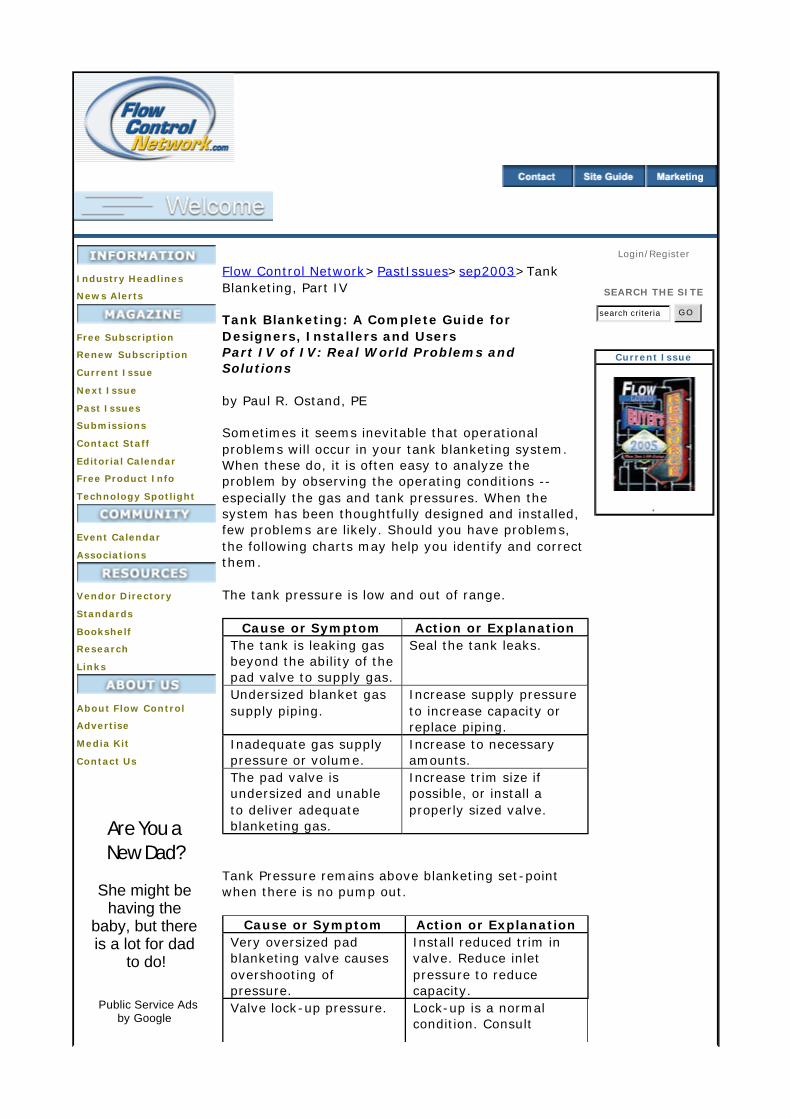
Flow Control Network>PastIssues>sep2003>Tank Blanketing, Part IV Tank Blanketing: A Complete Guide for Designers, Installers and Users Part IV of IV: Real World Problems and Solutions by Paul R. Ostand, PE Sometimes it seems inevitable that operational problems will occur in your tank blanketing system. When these do, it is often easy to analyze the problem by observing the operating conditions -- especially the gas and tank pressures. When the system has been thoughtfully designed and installed, few problems are likely. Should you have problems, the following charts may help you identify and correct them. The tank pressure is low and out of range.
Tank Pressure remains above blanketing set-point when there is no pump out.
Cause or Symptom Action or Explanation The tank is leaking gas beyond the ability of the pad valve to supply gas.
Seal the tank leaks.
Undersized blanket gas supply piping.
Increase supply pressure to increase capacity or replace piping.
Inadequate gas supply pressure or volume.
Increase to necessary amounts.
The pad valve is undersized and unable to deliver adequate blanketing gas.
Increase trim size if possible, or install a properly sized valve.
Cause or Symptom Action or Explanation Very oversized pad blanketing valve causes overshooting of pressure.
Install reduced trim in valve. Reduce inlet pressure to reduce capacity.
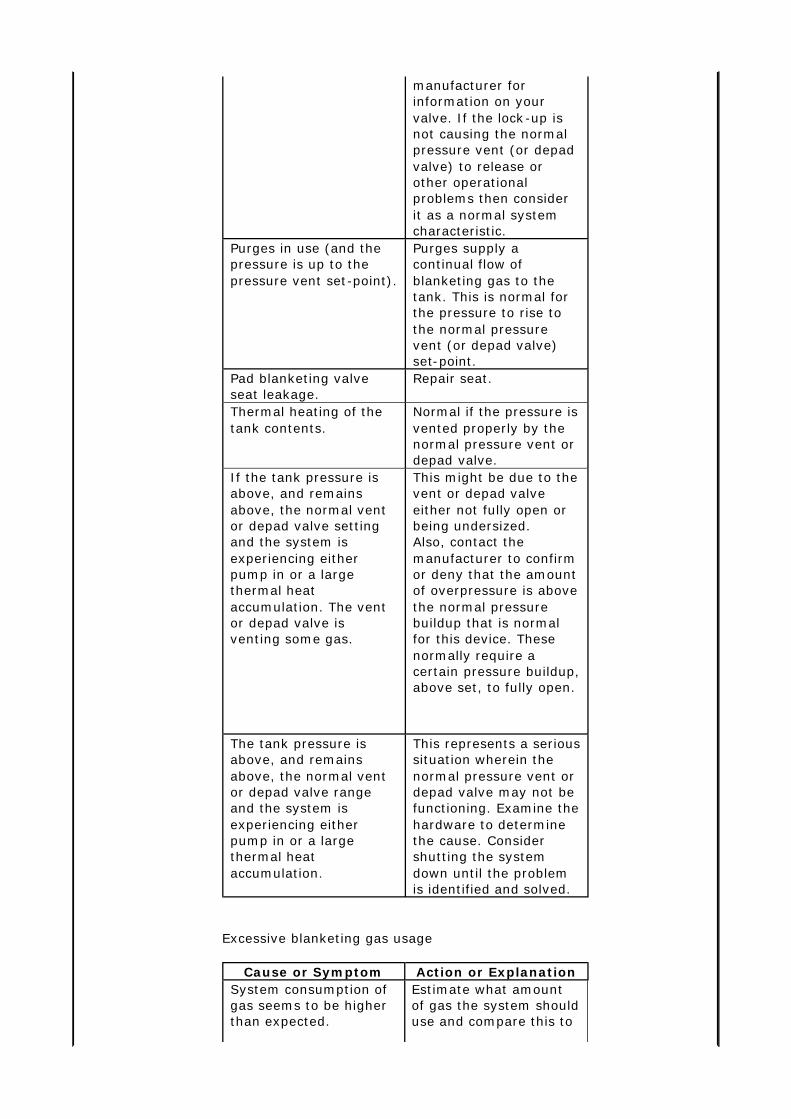
Valve lock-up pressure. Lock-up is a normal condition. Consult
Login/Register
SEARCH THE SITE
search criteria G O
Current Issue
.
Excessive blanketing gas usage
manufacturer for information on your valve. If the lock-up is not causing the normal pressure vent (or depad valve) to release or other operational problems then consider it as a normal system characteristic.
Purges in use (and the pressure is up to the pressure vent set-point).
Purges supply a continual flow of blanketing gas to the tank. This is normal for the pressure to rise to the normal pressure vent (or depad valve) set-point.
Pad blanketing valve seat leakage.
Repair seat.
Thermal heating of the tank contents.
Normal if the pressure is vented properly by the normal pressure vent or depad valve.
If the tank pressure is above, and remains above, the normal vent or depad valve setting and the system is experiencing either pump in or a large thermal heat accumulation. The vent or depad valve is venting some gas.
This might be due to the vent or depad valve either not fully open or being undersized. Also, contact the manufacturer to confirm or deny that the amount of overpressure is above the normal pressure buildup that is normal for this device. These normally require a certain pressure buildup, above set, to fully open.
The tank pressure is above, and remains above, the normal vent or depad valve range and the system is experiencing either pump in or a large thermal heat accumulation.
This represents a serious situation wherein the normal pressure vent or depad valve may not be functioning. Examine the hardware to determine the cause. Consider shutting the system down until the problem is identified and solved.
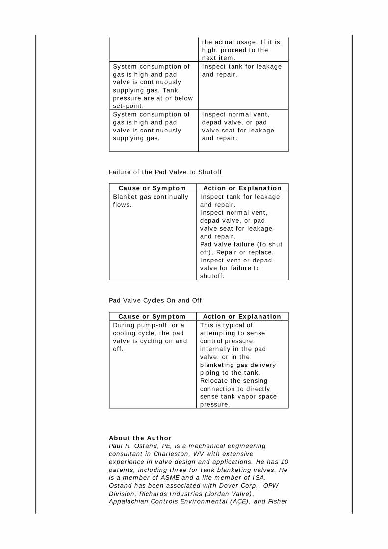
Cause or Symptom Action or Explanation System consumption of gas seems to be higher than expected.
Estimate what amount of gas the system should use and compare this to
Failure of the Pad Valve to Shutoff
Pad Valve Cycles On and Off
About the Author Paul R. Ostand, PE, is a mechanical engineering consultant in Charleston, WV with extensive experience in valve design and applications. He has 10 patents, including three for tank blanketing valves. He is a member of ASME and a life member of ISA. Ostand has been associated with Dover Corp., OPW Division, Richards Industries (Jordan Valve), Appalachian Controls Environmental (ACE), and Fisher
the actual usage. If it is high, proceed to the next item.
System consumption of gas is high and pad valve is continuously supplying gas. Tank pressure are at or below set-point.
Inspect tank for leakage and repair.
System consumption of gas is high and pad valve is continuously supplying gas.
Inspect normal vent, depad valve, or pad valve seat for leakage and repair.
Cause or Symptom Action or Explanation Blanket gas continually flows.
Inspect tank for leakage and repair. Inspect normal vent, depad valve, or pad valve seat for leakage and repair. Pad valve failure (to shut off). Repair or replace. Inspect vent or depad valve for failure to shutoff.
Cause or Symptom Action or Explanation During pump-off, or a cooling cycle, the pad valve is cycling on and off.
This is typical of attempting to sense control pressure internally in the pad valve, or in the blanketing gas delivery piping to the tank. Relocate the sensing connection to directly sense tank vapor space pressure.

Controls. He may be reached at [email protected] or 304 984-2889. His Web site is http://www.ostand.com/.
Subscribe | Site Map | Advertise
©2005 Grand View Media Group, Inc. All rights reserved. Unauthorized use prohibited.
Privacy Policy Terms of Use