manufactured by zuercher technik web: … · 2019-09-27 · tank blanketing systems where does...
TRANSCRIPT
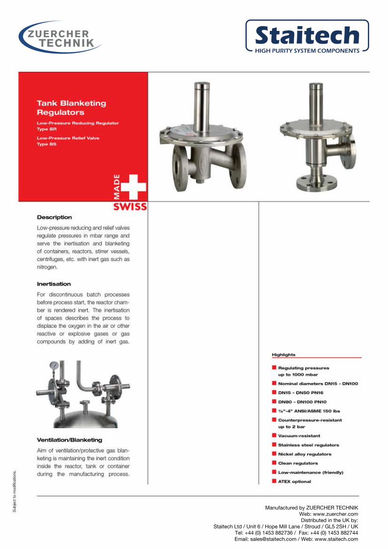
Manufactured by ZUERCHER TECHNIKWeb: www.zuercher.comDistributed in the UK by:
Staitech Ltd / Unit 6 / Hope Mill Lane / Stroud / GL5 2SH / UKTel: +44 (0) 1453 882736 / Fax: +44 (0) 1453 882744Email: [email protected] / Web: www.staitech.com

Technical Data
Sub
ject
tomod
ifica
tions
.
inletprocess
Reducing Regulator Function
Spring-loaded pressure reducing regulators are “relative pressure
regulators”, designed to keep the process pressure “B” at a con-
stant level. The nominal pressure is set by means of the setscrew,
located at the spring housing. When at rest, the regulator remains
in an open position. When the pressure “A” rises, pressure is
released through the open valve seat “F” to the process side of
the valve and through the internal feedback bore “E” underneath
the diaphragm. This will continue, until the diaphragm force “C”
exceeds the spring force “D”, while the process pressure “B”
rises. The diaphragm is lifted and the vale seat “F” closes. In the
event that the process pressure “B” drops below the pre-
adjusted nominal pressure, the spring force “D” presses the dia-
phragm downwards, so that the valve seat “F” opens and admits
gas until pressure equalization is reached again.
processoutlet
Relief Valve Function
Spring-loaded relief valves are “relative pressure regulators”,
designed to keep the process pressure “A” at a constant level.
The nominal pressure is set by means of the setscrew, located
at the spring housing. When at rest, the regulator remains in
a closed position. When the process pressure “A” increases,
pressure is released through the internal feedback bore “E”
underneath the diaphragm. If the diaphragm force “C” exceeds
the spring force “D” the valve seat “F” opens and the over pres-
sure is discharged to the vent side “B”. If the process pressure “A”
drops, the diaphragm force “C” is lower compared to the spring
force “D” and the valve seat “F” closes. The pressure in the vent
line can be atmospheric or vacuum. With vacuum in the vent line
the flow capacity of the regulator is increased.
Nominal Pressure Rating
Stainless steel casing : DN15 to DN50 16 bar
DN80 to DN100 10 bar
Max. inlet pressure : up to DN50 <_ 50°C 16 bar
at max. 150°C 13 bar
DN80 – DN100 <_ 50°C 10 bar
at max. 150°C 8 bar
Max. negative pressure : vacuum-resistant
Control range springs : -200 to 1000 mbar
Control range pilot pressure : -200 to 2000 mbar
Max. temp. FFKM (Kalrez®) : -20°C to +150°C
Max. temp. PKM (Viton®) : -20°C to +120°C
Max. temp. PVDF : -20°C to +130°C
Seat Tightness/Standard Setting
Seat tightness according to P12; EN 12266-1:2003;
leakage rate A
Flow rate at standard setting: DN 15 /1/2” : 0.5 Nm3/h
DN 25 / 1” : 1 Nm3/h
DN 40 /11/2” : 2 Nm3/h
DN 50 / 2” : 2 Nm3/h
DN 80 / 3” : 5 Nm3/h
DN 100 / 4” : 5 Nm3/h
Designs/Certificates
Design according to pressure equipment directive : DGR 97/23/EG
Marking >_ DN32 : CE0036
Declaration of Conformity QS 04 ATEX 2006 : II 2GD opt. IIC
FDA conformity for elastomers: : US.FDA 21 CFR
Factory Acceptance Certificate: : EN10204 2.2
EN10204 3.1
Sub
ject
tomod
ifica
tions
.
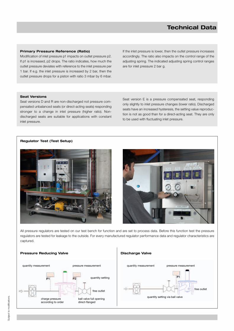
Regulator Test (Test Setup)
All pressure regulators are tested on our test bench for function and are set to process data. Before this function test the pressure
regulators are tested for leakage to the outside. For every manufactured regulator performance data and regulator characteristics are
captured.
Pressure Reducing Valve Discharge Valve
Primary Pressure Reference (Ratio)
Modification of inlet pressure p1 impacts on outlet pressure p2.
If p1 is increased, p2 drops. The ratio indicates, how much the
outlet pressure deviates with reference to the inlet pressure per
1 bar. If e.g. the inlet pressure is increased by 2 bar, then the
outlet pressure drops for a piston with ratio 3 mbar by 6 mbar.
If the inlet pressure is lower, then the outlet pressure increases
accordingly. The ratio also impacts on the control range of the
adjusting spring. The indicated adjusting spring control ranges
are for inlet pressure 2 bar g.
Seat Versions
Seat versions D and R are non-discharged not pressure com-
pensated unbalanced seats (or direct-acting seats) responding
stronger to a change in inlet pressure (higher ratio). Non-
discharged seats are suitable for applications with constant
inlet pressure.
Seat version E is a pressure compensated seat, responding
only slightly to inlet pressure changes (lower ratio). Discharged
seats have an increased hysteresis, the setting value reproduc-
tion is not as good than for a direct-acting seat. They are only
to be used with fluctuating inlet pressure.
Technical Data
quantity measurement quantity measurementpressure measurement pressure measurement
quantity setting
free outletfree outlet
charge pressureaccording to order
quantity setting via ball valveball valve full openingdirect-flanged

Typical Pressure Profile Of Discharge Valves
setting point e.g. 1 Nm3/hfor DN 25 regulator
flow rate
pressure
pressure drop at zero flow rate
pressure profile dome discharge valve
setting point e.g. 1 Nm3/hfor DN 25 regulator
pressure drop at zero flow rate
pressure increase spring-loaded
System-inducedcharacteristic ofspring-loaded dischargevalves:the regulated pressureincreases with increasingflow rate.
System-inducedcharacteristics of domedischarge valves:the regulated pressure staysconstant with increasingflow rate.
Typical Pressure Profile
The characteristic pressure profile is the best way to analyze
the pressure regulator system performance. For these pres-
sure profile diagrams the set pressure is indicated with refe-
rence to the flow rate (see below). The two profiles describe an
idealized pressure profile for a pressure reducing valve and a
discharge valve.
The regulators are not set static, but dynamic with low flow rate
(e.g. DN25 at 1 Nm3/h).
Pressure Regulator Characteristics
Sub
ject
tomod
ifica
tions
.
External Impulse Line
(Pressure Feedback)
If the secondary pressure is set below
10 mbar, or are pressure losses at the
pressure reducing valve outlet, e.g. due
to built-in instruments, to be expected,
which will exceed the set pressure at the
pressure reducing valve, then external
impulse line is to be considered. Also, if
quickly large flow rates are demanded.
horizontalinstallation
gradient min. 2%
Caution! Unconnected impulseline damages the pressurereducing valve!
System-inducedcharacteristic ofspring-loaded pressurereducing valves:the regulated outlet pressuredrops with increasingflow rate.
System-inducedcharacteristic of pressurereducing dome valves:the regulated outlet pressurestays constant with increasingflow rate.
Typical Pressure Profile Of Pressure Reducing Valves
pressure
pressure increase zero flow rate
setting point e.g. 1 Nm3/hfor DN 25 regulator
drop spring-loaded
flow rate
pressure
pressure increase zero flow rate
setting point e.g. 1 Nm3/hfor DN 25 regulator
pressure profile dome reducing valve

Standard Regulators
Application For processes, e.g. in chemical-pharmaceutical industry,without increased performance profile.
Design Inline and angle pattern/corner design.
Surfaces Without specific treatment.
Self-draiming Conditional.
Example of use Control processes for fluids and gases, no specific requirementsfor cleanliness and cleanability of the pressure regulator.
Vario Regulators
Application For processes, e.g. in chemical-pharmaceutical industry,with increased requirements for corrosion resistance.
Design Inline pattern.
Surfaces Without specific treatment, others on request.
Self-draiming Conditional.
Example of use Control processes for aggressive fluids and gases, no specificrequirements for cleanability of pressure regulator and deadspots.
Clean Regulators
Application For processes, e.g. in the pharmaceutical industry andfood processing, with increased requirements for surfaces,dead spots and cleanability.
Design Angle pattern.
Specials Corners replaced with radii, minimized dead space.
Surfaces Medium contact surfaces < Ra 0.8 µm.
Self-draiming Yes.
Example of use A typical application for these pressure valves is the regulationof sterile air (bio reactor).
Designs
Sub
ject
tomod
ifica
tions
.
Sub
ject
tomod
ifica
tions
.
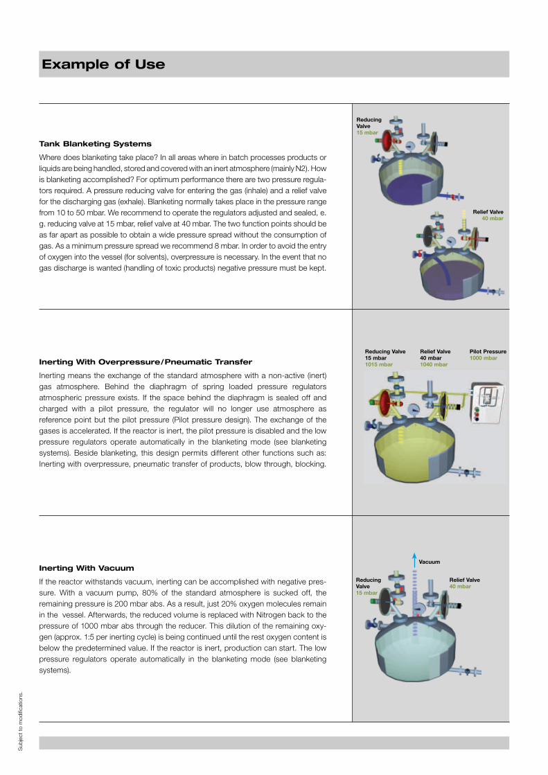
Tank Blanketing Systems
Where does blanketing take place? In all areas where in batch processes products orliquids are being handled, stored and coveredwith an inert atmosphere (mainly N2). Howis blanketing accomplished? For optimum performance there are two pressure regula-tors required. A pressure reducing valve for entering the gas (inhale) and a relief valvefor the discharging gas (exhale). Blanketing normally takes place in the pressure rangefrom 10 to 50 mbar. We recommend to operate the regulators adjusted and sealed, e.g. reducing valve at 15 mbar, relief valve at 40 mbar. The two function points should beas far apart as possible to obtain a wide pressure spread without the consumption ofgas. As a minimum pressure spread we recommend 8 mbar. In order to avoid the entryof oxygen into the vessel (for solvents), overpressure is necessary. In the event that nogas discharge is wanted (handling of toxic products) negative pressure must be kept.
Inerting With Overpressure/Pneumatic Transfer
Inerting means the exchange of the standard atmosphere with a non-active (inert)gas atmosphere. Behind the diaphragm of spring loaded pressure regulatorsatmospheric pressure exists. If the space behind the diaphragm is sealed off andcharged with a pilot pressure, the regulator will no longer use atmosphere asreference point but the pilot pressure (Pilot pressure design). The exchange of thegases is accelerated. If the reactor is inert, the pilot pressure is disabled and the lowpressure regulators operate automatically in the blanketing mode (see blanketingsystems). Beside blanketing, this design permits different other functions such as:Inerting with overpressure, pneumatic transfer of products, blow through, blocking.
Inerting With Vacuum
If the reactor withstands vacuum, inerting can be accomplished with negative pres-sure. With a vacuum pump, 80% of the standard atmosphere is sucked off, theremaining pressure is 200 mbar abs. As a result, just 20% oxygen molecules remainin the vessel. Afterwards, the reduced volume is replaced with Nitrogen back to thepressure of 1000 mbar abs through the reducer. This dilution of the remaining oxy-gen (approx. 1:5 per inerting cycle) is being continued until the rest oxygen content isbelow the predetermined value. If the reactor is inert, production can start. The lowpressure regulators operate automatically in the blanketing mode (see blanketingsystems).
ReducingValve15 mbar
Reducing Valve15 mbar1015 mbar
Relief Valve40 mbar1040 mbar
ReducingValve15 mbar
Relief Valve40 mbar
Vacuum
Pilot Pressure1000 mbar
Relief Valve40 mbar
Example of Use
Sub
ject
tomod
ifica
tions
.
Why Inertisation/Ventilation?
1. Explosion Protection
Excerpt ATEX 137:
Measures to prevent explosive atmospheres outplay all other
explosion prevention measures. By replacing the air mixture
with inert gas (inert substances are sluggish in reaction and do
not react within the respective reaction system) the formation
of an explosive atmosphere is prevented.
3. Oxidation Protection
Oxygen contained in the air can react or oxidize with other
substances. By replacing the air mixture in the container with
inert gas the forming of an oxidation-enabled atmosphere
is prevented. As a basic prerequisite for validation constant,
reproducible conditions are created.
4. Contamination Protection
Ventilation in positive pressure processes protects the product
from outside contamination. Ventilation in negative pressure
processes prevents contamination of the surroundings through
process substances.
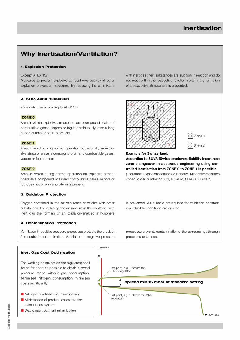
2. ATEX Zone Reduction
Zone definition according to ATEX 137
ZONE 0
Area, in which explosive atmosphere as a compound of air and
combustible gases, vapors or fog is continuously, over a long
period of time or often is present.
ZONE 1
Area, in which during normal operation occasionally an explo-
sive atmosphere as a compound of air and combustible gases,
vapors or fog can form.
ZONE 2
Area, in which during normal operation an explosive atmos-
phere as a compound of air and combustible gases, vapors or
fog does not or only short-term is present.
Example for Switzerland:
According to SUVA (Swiss employers liability insurance)
zone changeover in apparatus engineering using con-
trolled inertisation from ZONE 0 to ZONE 1 is possible.
(Literature: Explosionsschutz Grundsätze Mindestvorschriften
Zonen, order number 215Gd, suvaPro, CH-6002 Luzern)
Inertisation
Zone 1
Zone 2
set point, e.g. 1 Nm3/h forDN25 regulator
flow rate
set point, e.g. 1 Nm3/h for DN25regulator
pressure
spread min 15 mbar at standard setting
Inert Gas Cost Optimisation
The working points set on the regulators shall
be as far apart as possible to obtain a broad
pressure range without gas consumption.
Minimised nitrogen consumption minimises
costs significantly.
■ Nitrogen purchase cost minimisation
■ Minimisation of product losses into the
exhaust gas system
■ Waste gas treatment minimisation
inert gas
discharged air

Manufactured by ZUERCHER TECHNIKWeb: www.zuercher.comDistributed in the UK by:
Staitech Ltd / Unit 6 / Hope Mill Lane / Stroud / GL5 2SH / UKTel: +44 (0) 1453 882736 / Fax: +44 (0) 1453 882744Email: [email protected] / Web: www.staitech.com