11a - chapter 11, sec 11.1 - 11.3 black
TRANSCRIPT

7/25/2019 11A - Chapter 11, Sec 11.1 - 11.3 Black
http://slidepdf.com/reader/full/11a-chapter-11-sec-111-113-black 1/19
Heat Exchangers:
Design Considerations
Chapter 11
Sections 11.1 through 11.3
7/25/2019 11A - Chapter 11, Sec 11.1 - 11.3 Black
http://slidepdf.com/reader/full/11a-chapter-11-sec-111-113-black 2/19
Types
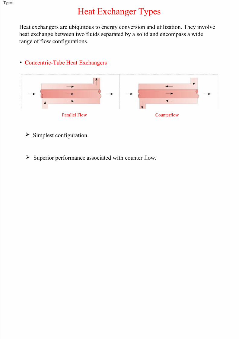
Heat Exchanger Types
Heat exchangers are ubiquitous to energy conversion and utiliation. They involve
heat exchange bet!een t!o "luids separated by a solid and enco#pass a !ide
range o" "lo! con"igurations.
$ Concentric%Tube Heat Exchangers
&arallel 'lo! Counter"lo!
Si#plest con"iguration.
Superior per"or#ance associated !ith counter "lo!.

7/25/2019 11A - Chapter 11, Sec 11.1 - 11.3 Black
http://slidepdf.com/reader/full/11a-chapter-11-sec-111-113-black 3/19
Types (cont.)
$ Cross%"lo! Heat Exchangers
'inned%*oth 'luids
+n#ixed
+n"inned%,ne 'luid -ixed
the ,ther +n#ixed
'or cross%"lo! over the tubes "luid #otion and hence #ixing in the transverse
direction ( y) is prevented "or the "inned tubes but occurs "or the un"inned condition.
Heat exchanger per"or#ance is in"luenced by #ixing.

7/25/2019 11A - Chapter 11, Sec 11.1 - 11.3 Black
http://slidepdf.com/reader/full/11a-chapter-11-sec-111-113-black 4/19
Types (cont.)
$ Shell%and%Tube Heat Exchangers
One Shell Pass and One Tube Pass
*a""les are used to establish a cross%"lo! and to induce turbulent #ixing o" the shell%side "luid both o" !hich enhance convection.
The nu#ber o" tube and shell passes #ay be varied e.g.:
,ne Shell &ass
T!o Tube &asses
T!o Shell &asses
'our Tube &asses

7/25/2019 11A - Chapter 11, Sec 11.1 - 11.3 Black
http://slidepdf.com/reader/full/11a-chapter-11-sec-111-113-black 5/19
Types (cont.)
$ Co#pact Heat Exchangers
/idely used to achieve large heat rates per unit volu#e particularly !hen
one or both "luids is a gas.
Characteried by large heat trans"er sur"ace areas per unit volu#e s#all"lo! passages and la#inar "lo!.
(a) 'in%tube ("lat tubes continuous plate "ins)
(b) 'in%tube (circular tubes continuous plate "ins)
(c) 'in%tube (circular tubes circular "ins)
(d) &late%"in (single pass)
(e) &late%"in (#ultipass)

7/25/2019 11A - Chapter 11, Sec 11.1 - 11.3 Black
http://slidepdf.com/reader/full/11a-chapter-11-sec-111-113-black 6/19
,verall Coe""icient
,verall Heat Trans"er Coe""icient
$ 0n essential require#ent "or heat exchanger design or per"or#ance calculations.
$ Contributing "actors include convection and conduction associated !ith the
t!o "luids and the inter#ediate solid as !ell as the potential use o" "ins on both
sides and the e""ects o" ti#e%dependent sur"ace "ouling.
$ /ith subscripts c and h used to designate the hot and cold "luids respectively
the #ost general expression "or the overall coe""icient is:
( ) ( )
( ) ( ) ( ) ( )
1 1 1
1 1
c h
f c f h
w
o o o oc c h h
UA UA UA
R R R
hA A A hAη η η η
= =
′′ ′′= + + + +

7/25/2019 11A - Chapter 11, Sec 11.1 - 11.3 Black
http://slidepdf.com/reader/full/11a-chapter-11-sec-111-113-black 7/19
,verall Coe""icient
( )o
,verall sur"ace e""iciency o" "in array (Section 3..2)
1 1
o
f
c or h f
c or h
A
A
η
η η
→
= − − ÷
total sur"ace area ("ins and exposed base) sur"ace area o" "ins onlyt
f A A A = →→
0ssu#ing an adiabatic tip the "in e""iciency is
( )
tanh f c or h
c or h
mL
mL
η
= ÷
( ) 4c or h p w c or h
m U k t =
partial overall coe1
""icient p c or h
f c or h
hU hR
= → ÷ ÷′′+
"or a unit sur" 'ouling "act ace area (# /)or 54 f R′′ → ×
Table 11.1→
conduction resistan/all (54/ce )w R →

7/25/2019 11A - Chapter 11, Sec 11.1 - 11.3 Black
http://slidepdf.com/reader/full/11a-chapter-11-sec-111-113-black 8/19
6-TD -ethod
0 -ethodology "or Heat Exchanger
Design Calculations% The 6og -ean Te#perature Di""erence (6-TD) -ethod %
$ 0 "or# o" 7e!ton8s 6a! o" Cooling #ay be applied to heat exchangers by using a log%#ean value o" the te#perature di""erence bet!een the t!o "luids:
1mq U A T ∆=
( )1
1
1 1n 4m
T T T
T T
∆ ∆∆
∆ ∆
−=
Evaluation o" depends on the heat exchanger type.1 andT T ∆ ∆
$ Counter%'lo! Heat Exchanger :
1 1 1
h c
h i c o
T T T
T T
∆ ≡ −
= −
h c
h o c i
T T T
T T
∆ ≡ −= −

7/25/2019 11A - Chapter 11, Sec 11.1 - 11.3 Black
http://slidepdf.com/reader/full/11a-chapter-11-sec-111-113-black 9/19
6-TD -ethod (cont.)
$ &arallel%'lo! Heat Exchanger :
1 1 1
h c
h i c i
T T T
T T
∆ ≡ −
= −
h c
h o c o
T T T T T
∆ ≡ −= −
7ote that T c,o can not exceed T h,o "or a &' H9 but can do so "or a C' H9.
'or equivalent values o" UA and inlet te#peratures
1 1 m CF m PF T T ∆ ∆>
$ Shell%and%Tube and Cross%'lo! Heat Exchangers:
1 1 m m CF T F T ∆ ∆=
'igures 11.1 % 11.13 F →

7/25/2019 11A - Chapter 11, Sec 11.1 - 11.3 Black
http://slidepdf.com/reader/full/11a-chapter-11-sec-111-113-black 10/19
Energy *alance
,verall Energy *alance
$ 0ssu#e negligible heat trans"er bet!een the exchanger and its surroundings and negligible potential and ;inetic energy changes "or each "luid.
( ) h i h ohq m i i×= −
( ) c c o c iq m i i×
= −
"luid enthalpyi →
$ 0ssu#ing no l/v phase change and constant speci"ic heats
( ) p h h i h ohq m c T T ×= − ( ) h h i h oC T T = −
( ) c p c c o c iq m c T T ×
= − ( ) c c o c iC T T = −
Heat capacity r sateh cC C →
$ 0pplication to the hot (h) and cold (c) "luids:

7/25/2019 11A - Chapter 11, Sec 11.1 - 11.3 Black
http://slidepdf.com/reader/full/11a-chapter-11-sec-111-113-black 11/19
Special Conditions
Special ,perating Conditions
Case (a): C h>>C c or h is a condensing vapor ( ) .hC → ∞
– 7egligible or no change in ( ) .h h o h iT T T =
Case (b): C c>>C h or c is an evaporating liquid ( ) .cC → ∞
– 7egligible or no change in ( ) .c c o c iT T T =
Case (c): C h=C c
1 1mT T T ∆ ∆ ∆= = –

7/25/2019 11A - Chapter 11, Sec 11.1 - 11.3 Black
http://slidepdf.com/reader/full/11a-chapter-11-sec-111-113-black 12/19
&roble#: ,verall Heat Trans"er Coe""icient
&roble# 11.2: Deter#ination o" heat trans"er per unit length "or heat recovery
device involving hot "lue gases and !ater.
&roble#: ,verall Heat Trans"er Coe""icient

7/25/2019 11A - Chapter 11, Sec 11.1 - 11.3 Black
http://slidepdf.com/reader/full/11a-chapter-11-sec-111-113-black 13/19
&roble#: ,verall Heat Trans"er Coe""icient
(cont.)
( ) ( ) ( )! oc c h14 +0 14 h0 < 14 h0
η = + +
( ) ( )
( )
i i1 =!
ln D 4 D ln 3:4 =< >.1: 1: 5 4 /.
;6 2: / 4 # 5 l#π π
−= = = ×
⋅
&roble#: ,verall Heat Trans"er Coe""icient
7/25/2019 11A - Chapter 11, Sec 11.1 - 11.3 Black
http://slidepdf.com/reader/full/11a-chapter-11-sec-111-113-black 14/19
&roble#: ,verall Heat Trans"er Coe""icient
(cont.)
&roble#: ,verall Heat Trans"er Coe""icient

7/25/2019 11A - Chapter 11, Sec 11.1 - 11.3 Black
http://slidepdf.com/reader/full/11a-chapter-11-sec-111-113-black 15/19
&roble#: ,verall Heat Trans"er Coe""icient
(cont.)
&roble#: ,verall Heat Trans"er Coe""icient

7/25/2019 11A - Chapter 11, Sec 11.1 - 11.3 Black
http://slidepdf.com/reader/full/11a-chapter-11-sec-111-113-black 16/19
&roble#: ,verall Heat Trans"er Coe""icient(cont.)
&roble#: ,cean Ther#al Energ Con ersion

7/25/2019 11A - Chapter 11, Sec 11.1 - 11.3 Black
http://slidepdf.com/reader/full/11a-chapter-11-sec-111-113-black 17/19
&roble#: ,cean Ther#al Energy Conversion
&roble# 11.=>: Design o" a t!o%pass shell%and%tube heat exchanger to supply
vapor "or the turbine o" an ocean ther#al energy conversion
syste# based on a standard (<an;ine) po!er cycle. The po!er
cycle is to generate -/e at an e""iciency o" 3?. ,cean
!ater enters the tubes o" the exchanger at 35 and its desired
outlet te#perature is @5. The !or;ing "luid o" the po!er
cycle is evaporated in the tubes o" the exchanger at its
phase change te#perature o" @5 and the overall heat trans"er
coe""icient is ;no!n.
&roble#: ,cean Ther#al

7/25/2019 11A - Chapter 11, Sec 11.1 - 11.3 Black
http://slidepdf.com/reader/full/11a-chapter-11-sec-111-113-black 18/19
&roble#: ,cean Ther#al Energy Conversion (cont)
&roble#: ,cean Ther#al

7/25/2019 11A - Chapter 11, Sec 11.1 - 11.3 Black
http://slidepdf.com/reader/full/11a-chapter-11-sec-111-113-black 19/19
&roble#: ,cean Ther#al
Energy Conversion (cont)