121207 initial engineering report 7087
TRANSCRIPT

Initial RDM Engineering Report On the Masterplan for
THE LAKES DEVELOPMENT NORTH BOAMBEE ROAD, COFFS HARBOUR
December 2007
RESOURCE DESIGN & MANAGEMENT PTY LTD Suite 34 Jetty Village Centre (PO Box J430)
COFFS HARBOUR NSW 2450 Phone (02) 6651 2688
Fax (02) 6651 3689
Email: [email protected]
Reference No: 07087CR01
© Reproduction of this document without prior permission is not permitted.

Engineering Report The Lakes Development, Coffs Harbour
Resource Design & Management Pty Ltd Page 1
TABLE OF CONTENTS 1. INTRODUCTION AND PURPOSE OF REPORT
2. WATER RETICULATION
3. ELECTRICITY
3.1 INTRODUCTION 3.2 OPTION 1 3.3 OPTION 2 3.4 EAST OF LAKE 5
4. SEWER RETICULATION
4.1 INTRODUCTION 4.2 CATCHMENT 1A 4.3 CATCHMENT 1B 4.4 CATCHMENT 2 4.4.1 WITHOUT RTA CORRIDOR 4.4.2 WITH RTA CORRIDOR
5. ANNEXURES
5.1 COFFS HARBOUR CITY COUNCIL SERVICING STRATEGY
5.2 CLARENCE CONSULTANTS “RELOCATION ROUTE OPTIONS REPORT” DATED 14/06/2005
5.3 CLARENCE CONSULTANTS LETTER DATED 10/12/2007
5.4 RDM DRAWINGS NUMBERED 07087/1-6

Engineering Report The Lakes Development, Coffs Harbour
Resource Design & Management Pty Ltd Page 2
1. INTRODUCTION AND PURPOSE OF THE REPORT Resource Design & Management (RDM) have been appointed to provide professional consulting engineering services with respect to updating the conceptual master plan for sewer and water supply services to the above proposed development. In addition, RDM have been tasked with co-ordinating the preferred underground solution for the relocation of the 66KVa overhead power line. Doug Gow and Associates, as project managers for this project have issued :-
• A base plan indicating the previous lot layout for the entire estate – Figure 4, Ref 5517-BF
• Additional lot information regarding revised zones to Stage 1.2 north of Lake 5
• Additional cadastral and some lot information regarding the newly acquired land east of lake 5.
• A report from Umwelt regarding the major stormwater detention system
• A report from Clarence Consultants (2005) regarding options for relocating the 66 KVa power line. In addition to this, and in order to allow engineering analysis to be rationally concluded, RDM have sourced lot layouts for the areas adjacent to the proposed development. These adjacent subdivisions include :-
• The proposed Golding subdivision west of Stage 9.2 • The proposed subdivision west of Stage 4.2
• The partially completed Central Grove estate east of Stage 2B
• The proposed subdivision east of Stage 6.2
• The proposed RTA highway corridor which passes through stages 8.2 and 9.2. This corridor
envelope was supplied by Coffs Harbour City Council (CHCC) and is their most recent available information regarding the highway corridor. We are advised that the RTA is refining the envelope and specific details may be available in the near future.
• Other adjacent lot and cadastral information from CHCC
All this information has been integrated to produce the masterplan base sheet which has been used throughout this report. The plans referred to in this report have been drawn at A1 size in an effort to achieve a balance between having sufficient detail across the full catchment areas. Although a set of A3 plans are embedded in the report, greater clarity is obtained by use of the larger attached drawings.

Engineering Report The Lakes Development, Coffs Harbour
Resource Design & Management Pty Ltd Page 3
2. WATER RETICULATION Refer to RDM drawing number (07087-1 Master Plan - Water Reticulation) The layout shown reflects the Coffs Harbour City Council Servicing Strategy defined in their “North Boambee Valley Information Sheet”- dated 22nd September, 2000. That strategy defines a network of main water supply lines desired by the Council to ensure adequate supply of potable water is available for the servicing of the area. The major elements of the strategy which are found within the development limits include :- • A 150 mm (diameter) main connecting the development to the existing 150 mm main in
Lophostemon Drive. Previously this connection was shown tracking up Road 14, turning East around Lake 5, and then across the boundary into the adjacent property. With Astoria’s acquisition of the land bounded by Hall’s Road and Lophostemon Drive, this extension of the 150 mm main will need to be integrated through the proposed development of this land.
• A 200 mm main in Lakes Drive connecting the Council 450 mm main in the West to the
development and reducing to 150 at the Road 14 intersection. (Lake 5) • Extending the 150 mm main north from Road 14/ Lake 5 to connect with the existing Council 600
main west of the Robert’s Hill Reservoir. • Extending the existing 150mm main which has been laid in Stages 1 & 2 west and north to link up
with the new 200 mm main to be laid in Lakes Drive. Within the framework of the main water supply network, the individual lots will be provided with reticulated water via a 100 mm main system. Generally these 100 mm service lines will form closed loops avoiding dead ends where possible. As the constructed stages approach the boundary of the development the individual 100 mm elements may need to connect with the adjacent development to provide continuity of supply. Council has devised this water supply scheme to provide both potable water and water for fire fighting purposes with sufficient head and in sufficient quantities. However, in the case of high density development (e.g. multi-storey units) further analysis of the local supply system may be required.

Engineering Report The Lakes Development, Coffs Harbour
Resource Design & Management Pty Ltd Page 4
3. ELECTRICITY
Re-routing of the existing overhead 66 KVa powerline onto a suitable underground alignment.
3.1 Introduction
Clarence Consultants produced a report in June 2005 regarding the options for the relocation of the overhead 66 KV line. The report addressed the whole of development scenario and nominated three solutions for the long tem development. In addition a short term temporary option was also suggested to allow the construction of Stage 2 without the capital intensive and fixed long term options. The three long term options suggested were :- a. Extend the overhead line up the eastern side of Lakes Drive for approximately 800 metres. Turning
south west, the proposed overhead line then tracks back to the existing at approximately pole 40233. Lay underground conduits up the eastern side of Lakes Drive in the Stage 2 area to allow future underground re-alignment if required.
b. Extend the line underground up the eastern side of Lakes Drive for approx 800 m. Switch to
overhead and link back to the existing at pole 40233 as above (underground option A of the 2005 report)
c. Extend the line underground along the eastern side of Lakes Drive for approximately 200 metres,
then turn South-west and track along the internal road system in a westerly direction to link up with the existing line half way between pole 40233 & 40234 (Underground option B of the 2005 report)
The client has indicated their preference is for a solution which optimises economy with underground sections in road reserves and other areas if practical and economical. The service provider has indicated that any underground sections should be as long as practical with minimum changes of direction. In the meantime the short term temporary diversion around Stage 2 has been implemented. This is an overhead line tracking up the eastern side of Lakes Drive approximately 200 metres, turning south west to link back to the existing overhead line at existing pole 40235. This short term diversion is shown on the plans. In order to translate the above identified options by Clarence Consultants into the latest development footprint as shown in the current masterplan, RDM after consultation with the Project Manager, Clarence Consultants and Astoria, has produced plans indicating two preferred alignments for consideration by all stakeholders. These two alignments are not exclusive and are subject to input by other stakeholders and related agencies. They may be amended or superseded in the interests of providing a solution compatible with the Clients perceived objectives. Additional investigation is required to cost out the selected options as well as reviewing potential lot rearrangement to access lower capital costs alignments. These two preferred options are discussed below.

Engineering Report The Lakes Development, Coffs Harbour
Resource Design & Management Pty Ltd Page 5
3.2 Option 1 – Routing the alignment along the shortest route within the proposed road reserve system.
Refer to RDM drawing number (07087-2 Master Plan - 66 KV Powerline - underground re-location – option 1) This option has a preferred underground alignment tracking approximately 160 metres up the eastern side of Lakes Drive, turning into Road No. 8, and then Road No. 13, and following the future internal road system to meet the existing overhead line in the reserve adjacent to the western boundary of the development. The entire line is underground except for the entry exit connections. The total length of line is approximately 650 metres. It includes 4 x 90 o changes of direction. The bends may be adjusted to accommodate the minimum radii allowed by the servicing authority. However, the points raised by Clarence Consultants (refer attached letter dated 11th December, 2007) are valid and may preclude agreement from the service authority to this alignment.
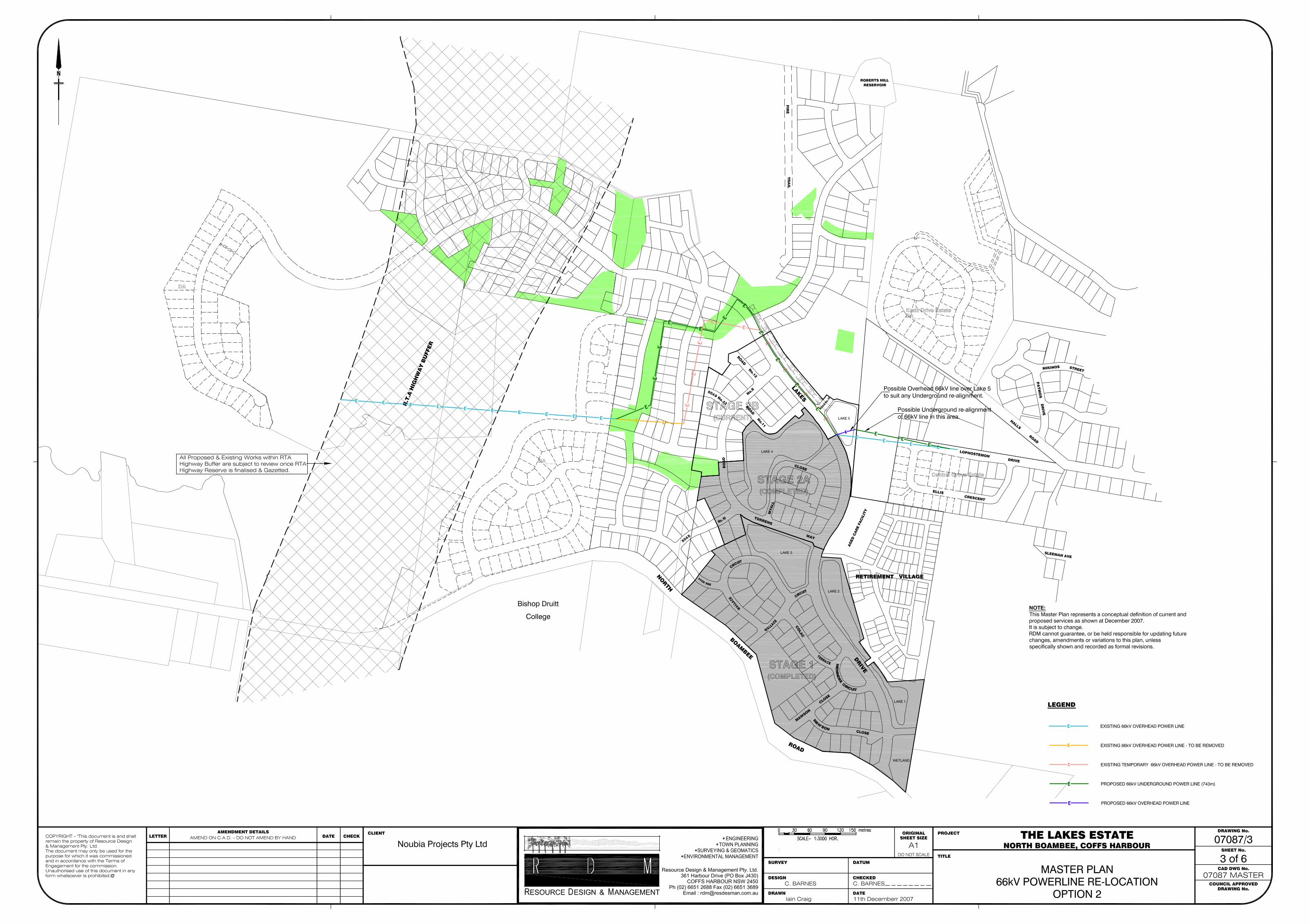
3.3 Option 2 – Routing the alignment along the shortest route within the proposed road reserve system and also using the reserve areas (Flora and Fauna linkages).
Refer to RDM drawing number (07087-3 Master Plan - 66 KV Powerline - underground re-location – option 2) The proposed alignment is underground up Lakes Drive (approximately 350 metres) and including the road crossing at that point into the reserve to the south west. The line then tracks approximately 400 metres along the area zoned as reserve, until reuniting with the existing overhead line in the reserve adjacent to the western boundary of the development. The total length of line is approximately 750 metres. It includes 2 x 90 o changes of direction. Similar concerns apply to this option regarding changes of direction but are less severe than option. In addition the changes of direction are predominantly in or next to “Reserve” areas. A possible variation to this option may be to consider making the section in the reserve overhead. This would remove the majority of the changes in direction issue. 3.4 East of Lake 5 With the purchase by Astoria of the land East of Lake 5 the option of undergrounding the 66 KV line in this area is raised. RDM have indicated this option in general terms without fixing any specific route – which is not possible as no lot layout is currently available. It raises the question of whether to re-align the line around Lake 5 altogether ? This should be considered in detail with the service provider once a lot layout concept is available.

Engineering Report The Lakes Development, Coffs Harbour
Resource Design & Management Pty Ltd Page 6
4. SEWER RETICULATION
4.1 Introduction The entire development extends across two major Council catchment areas. The overall wastewater capture and sewer reticulation is defined by the Coffs Harbour City Council Servicing Strategy as shown in the “North Boambee Valley Information Sheet”- dated 22nd September, 2000. The sewer reticulation servicing strategy plan in that document has the following major components :- • Pump station No. 50A servicing the catchment No. 2 to the west, and
• Pump station No. 50 servicing catchment No. 1A and No. 1B to the centre and eastern section of the
development. Pump station No. 50 also receives output from Pump Station No. 50A. Catchment No. 3 of the Council servicing strategy does not form part of this report. The strategy defined provides a collection network allowing all the proposed areas to be serviced by gravity sewer systems. Some earth-working is unavoidable to allow these gravity systems to be appropriately designed and constructed. However, this earth-working is likely to be secondary to the earth-working required to accommodate flood levels. Nevertheless in the detailed design stage this aspect will need to be evaluated and accommodated in the design documentation. Catchment 1 has been split into two parts – 1A and 1B. The reason for this is that the lakes system upstream of Lake 2 prevents these two sub-catchments being serviced by a single common sewer main. As a result there are two sewer mains servicing the catchment, and they are referred to as :- Sub-catchment 1A the eastern sub-catchment serviced by a 225 mm diameter sewer main East of
Lake 5 and routed north. Sub-catchment 1B the western sub-catchment serviced by a 300 mm diameter sewer main routed
up Lakes Drive

Engineering Report The Lakes Development, Coffs Harbour
Resource Design & Management Pty Ltd Page 7
4.2 Catchment 1A (Eastern sub-catchment) Refer to RDM drawing number (07087/4 Master Plan - Sewer Reticulation – Catchments 1A and 1B) This sub-catchment is serviced by a proposed (now partially constructed) 225 mm (diameter) sewer main tracking around Lake 2, North along the eastern edge of Lakes Drive and Lake 5, and then north along what is currently a boundary line as shown. It services not only the development area to the north of Lake 5, but also adjacent developments to the East. These contributing areas are identified in the drawing as well as the expected loading to the sewer. These contributing elements include :- • 20 Lots from the proposed subdivision Stage 2 of Lot 6, DP 852521, Kratz Drive Coffs Harbour.
(SMH O17) • 39 Lots from Stage 2 of “Central Grove Estate” (Village Building Copmpany) • 30 lots of the proposed development to the North of SMH O18 • 19 lots of the proposed development to the East of SMH O16 • 15 lots of the proposed development to the East of SMH O16 • 135 Retirement Village lots North and East of Lake 5 (SMH O13 – O16) A suggested layout is indicated on the drawing suggesting how the area may be serviced by a system of gravity lines feeding into the 225 main. The 225 line has sufficient capacity for this loading regime. Some filling of the site will be needed :- • In the low lying areas adjacent to Lake 5 • In the eastern sector between the channel and higher ground A significant stormwater drain servicing the area to the NNE will be required to cross this line in order to access Lake 5 at some point. We believe that the proposed line will have sufficient cover to allow this to occur north of Lake 5. 4.3 Catchment 1B (Western sub-catchment) Refer to RDM drawing number (07087/4 Master Plan - Sewer Reticulation – Catchments 1A and 1B) This area extends west to the ridge line – refer to the catchment boundary indicated on the plans. There is sufficient capacity in this line to accommodate significant additional loading. We have indicated a gravity sewer reticulation arrangement which will allow all of the sub-catchment to be serviced. This arrangement is only one option and the generous fall in the land will allow many variations to this as desired. The sub-catchment also acts a receiving system for the catchment 2 sewer pump station (PS 50A) – as is shown on the plan. It will also allow the reticulated wastewater from the Astoria development lots within Catchment 2 to be pumped into Catchment 1B if desired. This is dealt with in greater detail in sections 3.4.1 and 3.4.2 below.

Engineering Report The Lakes Development, Coffs Harbour
Resource Design & Management Pty Ltd Page 8
4.4 Catchment 2 4.4.1 Catchment 2 - option without RTA corridor
Refer to RDM drawing number (07087-5 - Master Plan - Sewer Reticulation – Catchment 2 – option without RTA corridor)
If the RTA preferred Highway Corridor was not considered, then the proposed Astoria development of approximately 96 lots in Catchment 2 could be serviced by a 150 mm diameter gravity system as shown in the plan. The collected wastewater would be directed to PS 50A using a 150 gravity main. This main can be installed without compromising the depth of the pump station required to service the adjacent contributing developments (Golding). It does however cross the adjacent land-holders property and an agreement with the said landholder would be required. If any impediment precluded approval to cross the adjoining land, a dedicated pump station would allow transfer of collected wastewater back to the 300 main in catchment 1B. 4.4.2 Catchment 2 - option with RTA corridor Refer to RDM drawing number (07087-6 - Master Plan - Sewer Reticulation – Catchment 2 – option with RTA corridor) If the RTA preferred Highway Corridor is taken into account, then much of the proposed Astoria development lots in this catchment will fall within the RTA corridor as shown on the plan. This leaves two smaller parcels of land either side of the corridor. We suggest that the western parcel may be difficult to service economically. The eastern parcel containing about 16 lots may be serviced either by a gravity connection to PS 50A, or by a small pump station pumping sewerage into the 300 mm line in Catchment 1B. Because of the uncertainty of the RTA corridor limits, we have not continued past this general strategy. Once the corridor is fixed and the general road arrangement adjusted it will be possible to identify specific solutions. We suggest that both solutions are feasible and economically viable.

Engineering Report The Lakes Development, Coffs Harbour
Resource Design & Management Pty Ltd Page 9
5. ANNEXURES 5.1 COFFS HARBOUR CITY COUNCIL SERVICING STRATEGY 5.2 CLARENCE CONSULTANTS PTY LTD “RELOCATION ROUTE OPTIONSREPORT” DATED
14/06/2005 5.3 CLARANCE CONSULTANTS LETTER DATED 10/12/2007 5.4 RDM DRAWINGS NUMBERED 07087/1-6

Update No. 1 to the RDM Engineering Report of December
2007 on the Masterplan for
THE LAKES DEVELOPMENT NORTH BOAMBEE ROAD, COFFS HARBOUR
November 2008
RESOURCE DESIGN & MANAGEMENT PTY LTD Suite 34 Jetty Village Centre (PO Box J430)
COFFS HARBOUR NSW 2450 Phone (02) 6651 2688
Fax (02) 6651 3689
Email: [email protected]
Reference No: 07087CR01
© Reproduction of this document without prior permission is not permitted.

Update No. 1 to the RDM Engineering Report of December 2007. The Lakes Development, Coffs Harbour
Master Plan Update
Resource Design & Management Pty Ltd Page 1
TABLE OF CONTENTS 1. INTRODUCTION AND PURPOSE OF REPORT
2. WATER RETICULATION
3. SEWER RETICULATION
3.1 INTRODUCTION 3.2 CATCHMENT 1A 3.3 CATCHMENT 1B
4. ANNEXURES
4.1 RDM DRAWING 07087/1A – MASTER PLAN – WATER RETICULATION
4.2 RDM DRAWING 07087/4A – MASTER PLAN – SEWER RETICULATION CATCHMENTS 1A & 1B

Update No. 1 to the RDM Engineering Report of December 2007. The Lakes Development, Coffs Harbour
Master Plan Update
Resource Design & Management Pty Ltd Page 2
1. INTRODUCTION AND PURPOSE OF THIS UPDATE NO.1 Previously in October 2007, Resource Design & Management (RDM) were appointed to provide professional consulting engineering services with respect to updating the conceptual master plan for sewer and water supply services to the above proposed development. Their initial report was issued to Doug Gow and Associates in December 2007. Since that issue some further amendments have been effected to the Master Plan. This “Update No. 1” represents the RDM response to the master plan amendments since December 2007 relating to the sewer and water reticulation. This information has been included on the amended drawings numbers :- • 07087-1A Master Plan - Water Reticulation – Update number 1. • 07087/4A Master Plan - Sewer Reticulation – Catchments 1A and 1B - Update number 1. Note:- • The infrastructure layouts illustrated in this report reflect the appropriate agency’s requirements.
For example, the sewer reticulation corresponds generally with the Coffs Harbour City Council strategic plan for this service in the area of interest. By conforming to the Council plan the proposal reflects infrastructure has the appropriate capacity for the land zoning.
• There is no physical or legal impediment that RDM is aware of to prevent services being located underground.
• Electricity and TELSTRA services have already been rolled out to stages 1 and 2 of this development. We understand that there is no restriction on the provision of these services to the remainder of the estate.
2. WATER RETICULATION Refer to RDM drawing number (07087-1A - Master Plan - Water Reticulation) The overall layout shown reflects the Coffs Harbour City Council Servicing Strategy defined in their “North Boambee Valley Information Sheet”- dated 22nd September, 2000. That strategy defines a network of main water supply lines as proposed by the Council to ensure adequate supply of potable water is available for the servicing of the area. The major elements of the strategy which are found within the development limits have been defined in our earlier December 2008 report. The reticulation network has been amended to suit the latest lot layout, and is shown in the amended drawing 07987-1A

Update No. 1 to the RDM Engineering Report of December 2007. The Lakes Development, Coffs Harbour
Master Plan Update
Resource Design & Management Pty Ltd Page 3
3. SEWER RETICULATION
3.1 Introduction As noted in the December 2007 report, the entire development extends across two major Council catchment areas. The overall wastewater capture and sewer reticulation is defined by the Coffs Harbour City Council Servicing Strategy as shown in the “North Boambee Valley Information Sheet”- dated 22nd September, 2000. The strategy defined provides a collection network allowing all the proposed areas to be serviced by gravity sewer systems. Some earth-working is unavoidable to allow these gravity systems to be appropriately designed and constructed. However, this earth-working is likely to be secondary to the earth-working required to accommodate flood levels. Nevertheless in the detailed design stage this aspect will need to be evaluated and accommodated in the design documentation. Catchment 1 has been split into two parts – 1A and 1B. The reason for this is that the lakes system upstream of Lake 2 prevents these two sub-catchments being serviced by a single common sewer main. As a result there are two sewer mains servicing the catchment, and they are referred to as :- Sub-catchment 1A the eastern sub-catchment serviced by a 225 mm diameter sewer main East of
Lake 5 and routed north. Sub-catchment 1B the western sub-catchment serviced by a 300 mm diameter sewer main routed
up Lakes Drive 3.2 Catchment 1A (Eastern sub-catchment) Refer to RDM drawing number (07087/4A - Master Plan - Sewer Reticulation – Catchments 1A and 1B – Update No. 1) This sub-catchment is serviced by a proposed (now partially constructed) 225 mm (diameter) sewer main tracking around Lake 2, North along the eastern edge of Lakes Drive and Lake 5. Currently it has been constructed as far as existing SMH O14 This sewer main services not only the development area to the north of Lake 5, but also adjacent developments to the East. These contributing areas are identified in the drawing as well as the expected loading to the sewer. These contributing elements include :- • 21 Lots from the proposed subdivision Stage 2 of Lot 6, DP 852521, Kratz Drive Coffs Harbour -
directed to the new SMH G1 • 60 Lots from Stage 2 of “Central Grove Estate” (Village Building Copmpany) and adjacent
undeveloped land in the east to the existing SMH O13. • 104 lots of the proposed development stage 1.2 and 6.2 to the North of new SMH A1 (including (a)
above) • 57 lots from the adjacent undeveloped land to the east to new SMH A1.

Update No. 1 to the RDM Engineering Report of December 2007. The Lakes Development, Coffs Harbour
Master Plan Update
Resource Design & Management Pty Ltd Page 4
A suggested sewer reticulation layout is indicated on the drawing indicating how the area may be serviced by a system of gravity lines feeding into the 225 main. The 225 line has sufficient capacity for this loading regime. Some filling of the site within this catchment in the low lying area around Lake 5 will be needed :- • In the areas to the north of the Lake 5 within the Stage 1.2 boundary • In the adjacent land to the east of Lake 5 owned by others The latest master plan lot arrangement of Stage 1.2 and 6.2 has been changed from the previous lot arrangement. Stage 1.2 has previously been designed and documented (but not yet submitted to Council) as “Stage 3” of the Lakes. As a consequence of the alteration to the lot layout in this area, the old Stage 3 design documentation will need to be reviewed and updated to accommodate this latest lot layout. A significant stormwater drain servicing the area to the NNE will be required to track south and cross this existing 225 line in order to access Lake 5 at some point. We believe that the existing 225 line has sufficient cover to allow this to occur at Lake 5, and this stormwater access into Lake 5 from the east over the sewer main has been documented into the Stage 3 design documents. 3.3 Catchment 1B (Western sub-catchment) Refer to RDM drawing number (07087/4A - Master Plan - Sewer Reticulation – Catchments 1A and 1B – Update No. 1) Generally the steeper slopes in this catchment allow some flexibility in the sewer reticulation design. As illustrated on the drawing 07087/4A, the proposed lot arrangement in this catchment may be serviced by a gravity system, and generally as described in the initial report. However, one area which differs noticeably from the initial Master Plan and will require filling is the eastern sector of stage 3.2. The proximity of that area to the stormwater flood lines suggests a rigorous assessment of the fill necessary to enable the proposed gravity system design to function correctly will be required. This may be addressed in depth in the detailed design stage of stage 3.2.
4. ANNEXURES 4.1 RDM DRG 07087/1A – MASTER PLAN – WATER RETICULATION – UPDATE NO. 1 4.2 RDM DRG 07087/4A – MASTER PLAN – SEWER RETICULATION CATCHMENTS 1A AND 1B –
UPDATE No. 1