12d solutions pty ltd - 12d model - civil engineering, water … part 2.pdf · · 2014-01-07the...
TRANSCRIPT

12d Solutions Pty LtdCivil and Surveying Software
Version 8 Course Notes
STORMWATER DESIGN - Part 2
12d Solutions Pty Limited
ACN 056 019 713
Phone: +61 (2) 9970 7117 Fax: +61 (2) 9970 7118Email [email protected]
CIVIL AND
SURVEYING SOFTWARE
THE 12D PERSPECTIVE

12d Stormwater Course - Part 2 Notes
These course notes assume that the trainee has the basic 12d Model skills usually obtained
from the “12d Model Training Manual”
These notes are intended to cover basic Stormwater Design. For more information regarding
training courses contact 12d Solutions Training Manager.
These notes were prepared by
Robert Graham
Revised July 2008
Copyright © 12d Solutions Pty Limited 2008
These notes may be copied and distributed freely.
Disclaimer
12d Model is supplied without any express or implied warranties whatsoever.
No warranty of fitness for a particular purpose is offered.
No liabilities in respect of engineering details and quantities produced by 12d Model are
accepted.
Every effort has been taken to ensure that the advice given in these notes and the program 12d
Model is correct, however, no warranty is expressed or implied by 12d Solutions.
Copyright © 12d Solutions Pty Limited 2007
Revised July 2008 12d Stormwater Course - Part 2 Notes Page 3 of 109
12d Solutions Pty Ltd
COURSE NOTES
STORMWATER DESIGN - Part 2
1.0 Stormwater Design Part 2- Introduction ................................................................................. 5
2.0 Starting with a Basic Drainage Network ................................................................................. 6
3.0 Setup Files and Their Locations ............................................................................................... 6
4.0 Bypass Flow .............................................................................................................................. 10
4.1 Drawing Bypass Flow Strings ........................................................................................ 10
4.2 Set Pit Details - Calculate the Bypass Flow Data ........................................................... 16
5.0 The drainage.4d file ................................................................................................................. 21
5.1 Pit Inlet Capacities .......................................................................................................... 23
6.0 12d Storm Analysis Bypass and Flooded Width Calculations ............................................. 26
7.0 Major Flood Events.................................................................................................................. 28
8.0 Open Channel Flow.................................................................................................................. 30
9.0 Excavation Quantities .............................................................................................................. 34
10.0 Network Quantities Report ..................................................................................................... 37
11.0 Exporting to Drainage Design Software Packages................................................................ 42
12.0 Drainage Data Input and Output to Spreadsheets................................................................ 44
12.1 12d to spreadsheet transfers ............................................................................................ 44
12.2 “12d drainage spreadsheet” Format ................................................................................ 50
12.3 12d Drainage Variable Names ........................................................................................ 52
13.0 Running PCdrain for Windows .............................................................................................. 54
13.1 PCdrain Requirements .................................................................................................... 54
13.2 12d to PCdrain ................................................................................................................ 56
13.3 PCdrain to 12d ................................................................................................................ 57
14.0 Running Drains - Version 2 onwards ..................................................................................... 58
14.1 Drains Interface Overview.............................................................................................. 58
14.2 Catchment Data............................................................................................................... 59
14.3 Synchronising the Drains database and the drainage.4d file. ......................................... 59
14.4 Drains to drainage.4d file................................................................................................ 61
14.5 Editing the Drainage.4d file............................................................................................ 63
14.6 Setting the Overflow Route, the Pit and Pipe types........................................................ 64
14.7 Drains Version 2+ Requirements.................................................................................... 66
14.8 12d to Drains................................................................................................................... 67
14.9 Drains to 12d Update ...................................................................................................... 68
14.10 Drains Mapping File ....................................................................................................... 69
15.0 Running XPSWMM and RAT2000........................................................................................ 71
15.1 xpstorm and xpswmm bypass requirements ................................................................... 71
15.2 12d to the XP Programs .................................................................................................. 74
15.3 XP Programs to 12d ........................................................................................................ 76
16.0 Detailed Drainage Plan Drawing - Creating MH Symbols .................................................. 79
17.0 User Defined Attributes........................................................................................................... 82
17.1 Drainage Pit attributes .................................................................................................... 83
17.2 Drainage Pipe attributes.................................................................................................. 86
18.0 Detailed Drainage Plan Drawing ............................................................................................ 88
19.0 Drainage Long Section Plotting - Hatching Under Roads ................................................... 92
Revised July 2008 12d Stormwater Course - Part 2 Notes Page 4 of 104
19.1 Creating the Obvert strings..............................................................................................92
19.2 Create and Null the Obvert tin.........................................................................................94
19.3 Create a Roads Only Tin .................................................................................................95
19.4 Use the Hatching Feature in Drainage Longsections ......................................................98
20.0 Flooded Width Analysis and HEC RAS ...............................................................................102
20.1 Limitations where overland flow lines join...................................................................102
20.2 Limitations at SAG pits .................................................................................................102
20.3 Cross Sections, Discharges and Warnings ....................................................................104
21.0 Drainage Overflow Areas from Volumes .............................................................................106
22.0 Appendices...............................................................................................................................109
22.1 Appendix A: 12d V8 Drainage Analysis Detention Basins ..........................................109
22.2 Appendix B: 12d V8 Drainage Analysis Hydraulics ....................................................109
22.3 Appendix C: 12d V8 Drainage Analysis Ku Kw ..........................................................109

Revised July 2008 12d Stormwater Course - Part 2 Notes: Page 5 of 110
12d Solutions Pty Ltd
COURSE NOTES
STORMWATER DESIGN - Part 2
1.0 Stormwater Design Part 2- Introduction
The Stormwater Design Course Part 1 and this manual, the Stormwater Design Part , describe
the functions and processes of the 12d drainage module. In these documents, the generic term pit
refers manholes inlets, catch basin and manholes.
The Stormwater Design Course - Part 1 Notes contain:
s create a super tin for pipe cover and pit cover levels,
s set drainage defaults and layout a drainage network from CAD and in 12d,
s use the 12d drainage network editor to assign names to the pit/pipes, avoid service
clashes, grade pipes, align obverts, minimise depth and many other design tools,
s designate catchment areas and produce catchment plans,
s run the 12d storm rational hydrology and hydraulics engine,
s transfer data to and from electronic spreadsheets to enable the user to easily review
the data and add user defined data to the 12d pipe network. This data may include
such data as pipe bedding types and trench width,
s create a drainage template containing customised default design parameters,
s create pit setout schedules to export to spreadsheets or word processors for final for-
matting,
s produce long section drainage profiles including HGL data, flows, invert levels and
service crossings,
s create plan drawings with pipe sizes, flows, pit symbols, linestyles for pipe sizes,
design parameters for pit and pipes and user defined data,
s locate pits/manholes at exact chainage and offset locations.
This manual, the Stormwater Design Course - Part 2, is intended to describe the additional fea-
tures of 12d model drainage and discuss the customisation of the package. This will include
s customising the drainage.4d file,
s 12d storm analysis with inlet capacity calculations and bypass flow,
s flooded width analysis and flooding at SAG pits,
s drainage trench excavation volume calculations,
s pipe and pit quantity calculations/reports,
s open channel calculations,
s adjusting pit locations for changes in horiz road geometry
s analysing the major flood events,
s design or evaluate the drainage system using by creating input files for the xpswmm/
xprat-hgl, Windes, Drains and PCdrain drainage design packages,
s read the output from the drainage design packages and update the drainage network
plus storing the hydraulic data, such as hgl (hydraulic grade line) levels, peak pipe
Revised July 200812d Stormwater Course - Part 2 Notes: Page 6 of 110
12d Solutions Pty Ltd
COURSE NOTES
STORMWATER DESIGN - Part 2
flows and pipe capacities,
s creating drainage symbols with grates and upstream side inlets,
s detailed drainage plan labelling and long sections with hatching under roads.
2.0 Starting with a Basic Drainage Network
In this document, the generic term pit refers to manholes, inlets, catch basin and manholes. When the
term manhole is used on the 12d menu system it refers to any type of pit. Pit types, dimensions and
inlet capacities of the pits are set in the drainage.4d file.
These course notes assume that you have completed the Stormwater Design Course and that you
have experience creating 12d model drainage networks with catchments areas. This course will
begin with a completed drainage design found in the directory
\12djobs\8.00\Courses\Drainage_Analysis
The project name is Local Road Complete.
3.0 Setup Files and Their Locations
The drainage module consists of the optional 12d Drainage Analysis, utilities, startup configuration
files for RAT2000, XP SWMM and the 12d drainage configuration file (drainage.4d).
All setup files have been configured for the training version. However, when you start working on
real projects you may want customise the drainage module. More - Customising the drainage
module
The drainage.4d file contains pipe types (RCP, Class 2 etc.) and example pit inlet capacites for inlet
pits. Detailed pit type descriptions and internal pit dimensions can be included in this file to be
inserted into your pit schedules. For PCdrain and Drains users there are routines to read your gully
pit/database files and create the drainage.4d file More.
REVIEW THIS DATA CAREFULLY! The drainage.4d file may be customised for any additional
inlet capacity data you may have.
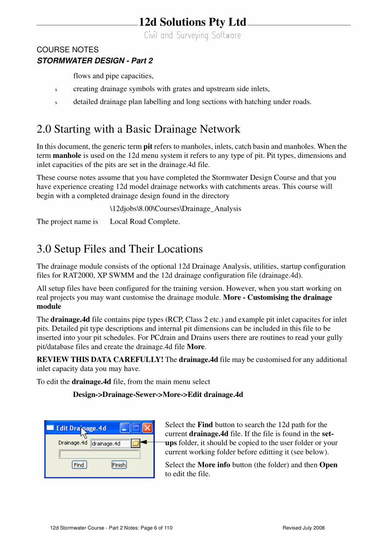
To edit the drainage.4d file, from the main menu select
Design->Drainage-Sewer->More->Edit drainage.4d
Select the Find button to search the 12d path for the
current drainage.4d file. If the file is found in the set-
ups folder, it should be copied to the user folder or your
current working folder before editting it (see below).
Select the More info button (the folder) and then Open
to edit the file.
Revised July 2008 12d Stormwater Course - Part 2 Notes: Page 7 of 110
12d Solutions Pty Ltd
COURSE NOTES
STORMWATER DESIGN - Part 2
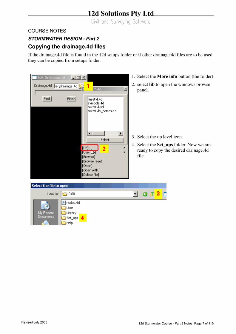
Copying the drainage.4d files
If the drainage.4d file is found in the 12d setups folder or if other drainage.4d files are to be used
they can be copied from setups folder.
1. Select the More info button (the folder)
2. select lib to open the windows browse
panel.
3. Select the up level icon.
4. Select the Set_ups folder. Now we are
ready to copy the desired drainage.4d
file.

Revised July 200812d Stormwater Course - Part 2 Notes: Page 8 of 110
12d Solutions Pty Ltd
COURSE NOTES
STORMWATER DESIGN - Part 2
You must restart 12d for these changes to become active. Select Project->Restart!
5. type dr*.4d and press Enter to get a list of the drainage.4d files.
6. RB the desired file
7. Select Copy to place the file on the clipboard.
8. select the Up level icon to move back up a level
9. Select the User folder
10.RB in the white space and then selectPaste.
11.The file can now be renamed drainage.4d if it had another name.

Revised July 2008 12d Stormwater Course - Part 2 Notes: Page 9 of 110
12d Solutions Pty Ltd
COURSE NOTES
STORMWATER DESIGN - Part 2
At startup, if there are significant errors in the file, refer to the output window where 12d will
print the line number where it give up. When looking in the long list of files, the drainage.4d file
is loaded after the shp files.
See “The drainage.4d file” on page 21.
REVIEW THIS DATA CAREFULLY! A detailed description of the pit inlet capacity tables in
this file is given in “Pit Inlet Capacities” on page 23. The drainage.4d file may be customised for
any additional inlet capacity data you may have.

Revised July 200812d Stormwater Course - Part 2 Notes: Page 10 of 110
12d Solutions Pty Ltd
COURSE NOTES
STORMWATER DESIGN - Part 2
4.0 Bypass Flow
Bypass flow strings are used to trigger the bypass calculations in the network editor and are used as a
centre line for flooded width calculations. The later requires unique names for the bypass flow
strings.
The 12d storm analysis, and many of the design programs 12d exports to, allow for bypass flow.
Bypass flow involves the calculation of inlet capacity which is based on the pit type and often on the
road grade and/or crossfall upstream of the inlet.
Key Points
1. Set the pit type. (Pit Type on the Pit tab). For the 12d storm analysis these pit types must have
inlet capacity data in the drainage.4d file.
2. Set the Inlet config on the Pit->Main tab (Manhole, Ongrade or SAG). This selection will be dis-
abled if cap_config parameter sets the structure type in the drainage.4d file. Manholes have no
inlet capacity and are not considered inlets (sealed), on grade inlets capture the water as it passes
the inlet while SAG inlets trap the water flowing in from all directions (until the catchment over-
flows at the low point).
3. Draw an bypass flow string in the direction of flow so that it passes within 1 pit diameter of an
inlet. When bypass flow strings join they must join within 1 pit diameter of an inlet (Manhole
types are not considered inlets). If flooded with calculations are to be done later, the bypass flow
string must have a unique name and the string should located in the flow channel.
Enter the model name in the Bypass flow model field on the Global->Utility Models tab.
4. Many bypass strings may join at an inlet but only one bypass string should leave each inlet.
5. On grade pits may require road grade and/or crossfall data for inlet capacity. A setout string link is
required to measure road grade. If road crossfall is needed then the centre string is also required.
These strings are specified using the Road design file on the Global->Utility Models tab.
6. Pond depth measurements for a SAG inlet require a link to a catchment string. Also check that
your grate level is correct (Grate rl mode).
7. Press the Set Pit Details button. Road grades, crossfalls, ponding depths and bypass pits will now
be found on the Pit->Bypass tab of the Network Editor.
8. Bypass pits may be cleared using Clear Bypass Links on the Globals->Utility Models tab
9. Storm Analysis must have Consider Bypass Flows selected.
4.1 Drawing Bypass Flow Strings
The bypass flow string must be within 1. pit diameter of the drainage pit in be considered on the
bypass flow path. If the bypass flow string is to be used for flooded width calculations in the future,
the string must also be drawn in the main flow area of the cross section.
For project with roads it is easiest to copy a road string (invert strings are usually the best) into the
flow model and then check the string to see if it flows down hill. You may be required reverse the
direction of some strings, split some strings at major crests, join some strings that do not meet at

Revised July 2008 12d Stormwater Course - Part 2 Notes: Page 11 of 110
12d Solutions Pty Ltd
COURSE NOTES
STORMWATER DESIGN - Part 2
inlets and finally add some flow lines where flow crosses the road.
Copying the Invert strings into the bypass model
First we will create a new view for just the road strings.
View->Create->Plan view
10.Type Roads
11.Select Create
1. Place your point over the + button and press
Shift+r to display all of the models starting with
R.
2. Drag your pointer across all of the road models to
select them
3. Lb the Select button to add them to the view.
Revised July 200812d Stormwater Course - Part 2 Notes: Page 12 of 110
12d Solutions Pty Ltd
COURSE NOTES
STORMWATER DESIGN - Part 2
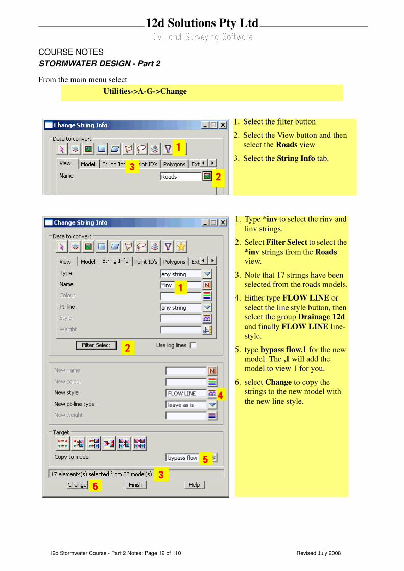
From the main menu select
Utilities->A-G->Change
1. Select the filter button
2. Select the View button and then
select the Roads view
3. Select the String Info tab.
1. Type *inv to select the rinv and
linv strings.
2. Select Filter Select to select the
*inv strings from the Roads
view.
3. Note that 17 strings have been
selected from the roads models.
4. Either type FLOW LINE or
select the line style button, then
select the group Drainage 12d
and finally FLOW LINE line-
style.
5. type bypass flow,1 for the new
model. The ,1 will add the
model to view 1 for you.
6. select Change to copy the
strings to the new model with
the new line style.

Revised July 2008 12d Stormwater Course - Part 2 Notes: Page 13 of 110
12d Solutions Pty Ltd
COURSE NOTES
STORMWATER DESIGN - Part 2
Splitting the Strings at Major Crests
If the roads contain a major crest that defines a separate catchment then the flow lines will need to
be split so that one segment can be reversed.
If you have labelled the crests and sag points then you can use these labels to quickly identify the
crests.
1. Drag out the CAD string toolbar and select the String split icon.
2. Instructions will be given in the 12d message area (bottom left corner of the screen). Pick
and accept the string to be split.
3. Pick and accept the split point or if you have them the crest marker. The string will now be
split.
repeat steps 2 and 3 for all strings to be split. Press ESC when finished.
Revised July 200812d Stormwater Course - Part 2 Notes: Page 14 of 110
12d Solutions Pty Ltd
COURSE NOTES
STORMWATER DESIGN - Part 2
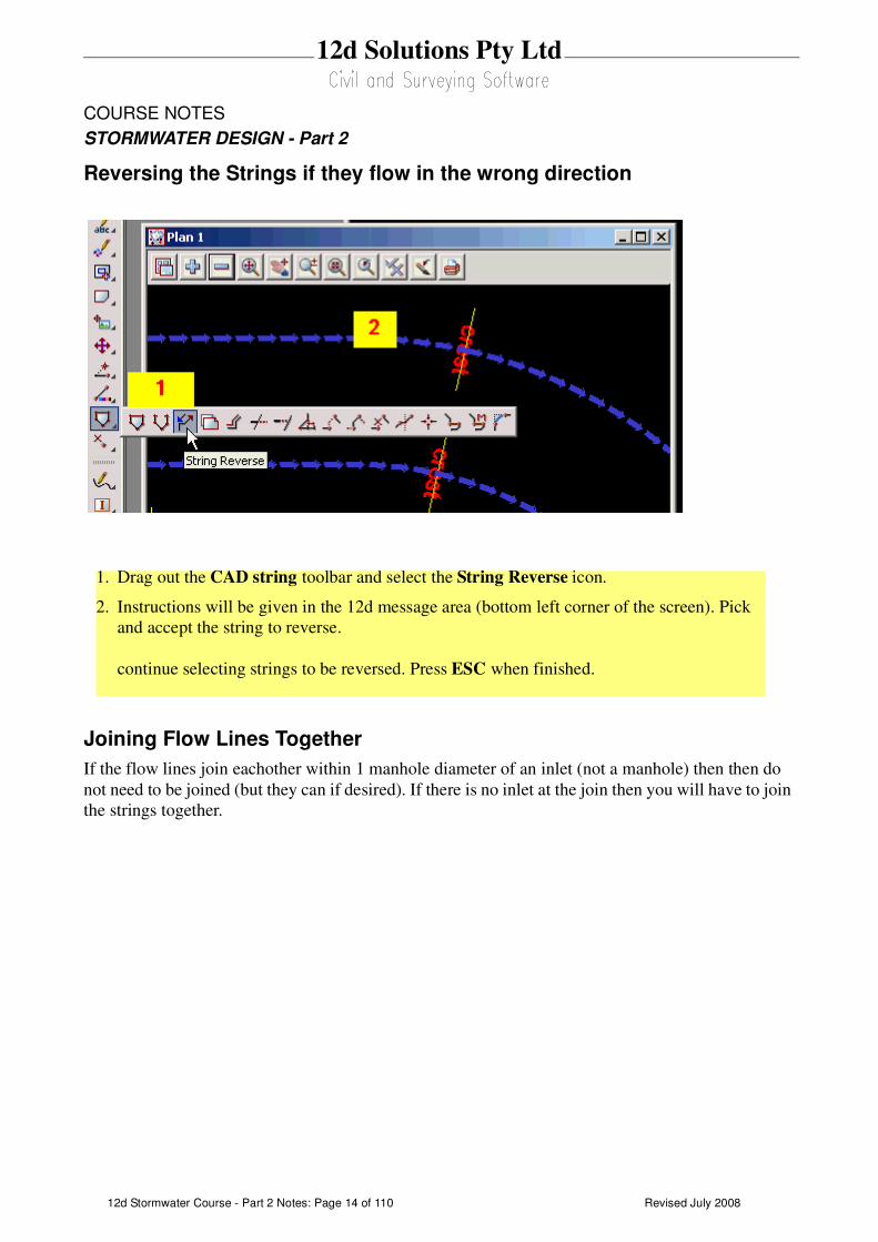
Reversing the Strings if they flow in the wrong direction
Joining Flow Lines Together
If the flow lines join eachother within 1 manhole diameter of an inlet (not a manhole) then then do
not need to be joined (but they can if desired). If there is no inlet at the join then you will have to join
the strings together.
1. Drag out the CAD string toolbar and select the String Reverse icon.
2. Instructions will be given in the 12d message area (bottom left corner of the screen). Pick
and accept the string to reverse.
continue selecting strings to be reversed. Press ESC when finished.

Revised July 2008 12d Stormwater Course - Part 2 Notes: Page 15 of 110
12d Solutions Pty Ltd
COURSE NOTES
STORMWATER DESIGN - Part 2
Adding additional flow lines where the flow cross the road
Use the CAD toobar to create the bypass flow paths. A unique name is required if you plan to
calculated flooded widths after the analysis is done.
Starting at the upstream end. LB select an insertion point and MB or press return to accept the
selection. Continue this until you reach the end of the flow path. The string will not be shown in
the new linestyle until the screen is redrawn. Press ESC to finish drawing the string. MB on the
1. Drag out the CAD string
toolbar and select the String Join icon.
2. Instructions will be given in the 12d message area (bottom left corner of the screen). Pick
and accept the upstream string then pick and accept the downstream string. Since they are
already drawn in the same direction you will not have to use a directional pick.
continue selecting strings to be joined. Press ESC when finished.
To use the CAD toolbar go to the CAD data bar and enter a
string name and model name. Select the line style (optional).
DRAG the Create line button and release at
the Create Line String button.
When finished drawing the string press ESC.
Revised July 200812d Stormwater Course - Part 2 Notes: Page 16 of 110
12d Solutions Pty Ltd
COURSE NOTES
STORMWATER DESIGN - Part 2
plan view title area to redraw the screen. The correct linestyle will now appear.
If you reach a sag pit location you may terminate the string or continue defining the bypass flow path
for a surcharging event out of the sag location.
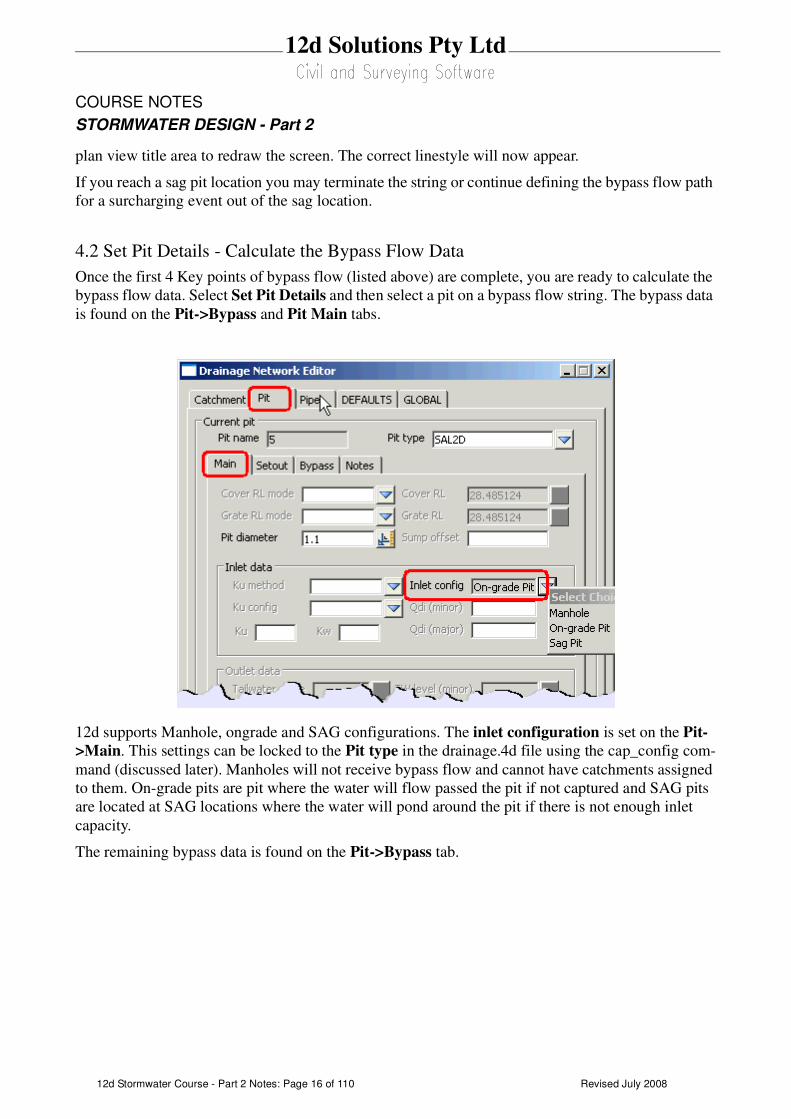
4.2 Set Pit Details - Calculate the Bypass Flow Data
Once the first 4 Key points of bypass flow (listed above) are complete, you are ready to calculate the
bypass flow data. Select Set Pit Details and then select a pit on a bypass flow string. The bypass data
is found on the Pit->Bypass and Pit Main tabs.
12d supports Manhole, ongrade and SAG configurations. The inlet configuration is set on the Pit-
>Main. This settings can be locked to the Pit type in the drainage.4d file using the cap_config com-
mand (discussed later). Manholes will not receive bypass flow and cannot have catchments assigned
to them. On-grade pits are pit where the water will flow passed the pit if not captured and SAG pits
are located at SAG locations where the water will pond around the pit if there is not enough inlet
capacity.
The remaining bypass data is found on the Pit->Bypass tab.
Revised July 2008 12d Stormwater Course - Part 2 Notes: Page 17 of 110
12d Solutions Pty Ltd
COURSE NOTES
STORMWATER DESIGN - Part 2
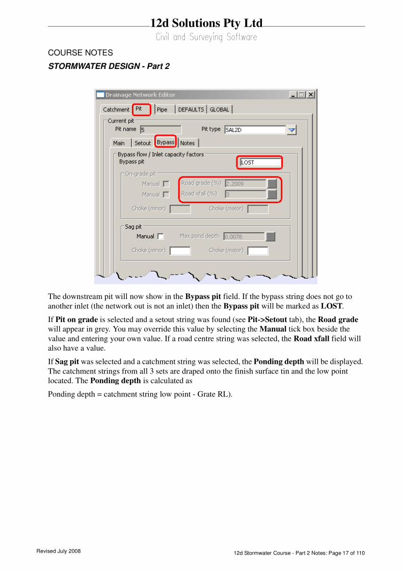
The downstream pit will now show in the Bypass pit field. If the bypass string does not go to
another inlet (the network out is not an inlet) then the Bypass pit will be marked as LOST.
If Pit on grade is selected and a setout string was found (see Pit->Setout tab), the Road grade
will appear in grey. You may override this value by selecting the Manual tick box beside the
value and entering your own value. If a road centre string was selected, the Road xfall field will
also have a value.
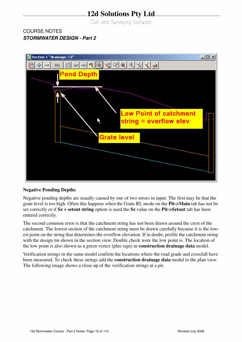
If Sag pit was selected and a catchment string was selected, the Ponding depth will be displayed.
The catchment strings from all 3 sets are draped onto the finish surface tin and the low point
located. The Ponding depth is calculated as
Ponding depth = catchment string low point - Grate RL).
Revised July 200812d Stormwater Course - Part 2 Notes: Page 18 of 110
12d Solutions Pty Ltd
COURSE NOTES
STORMWATER DESIGN - Part 2
Negative Ponding Depths
Negative ponding depths are usually caused by one of two errors in input. The first may be that the
grate level is too high. Often this happens when the Grate RL mode on the Pit->Main tab has not be
set correctly or if Sz + setout string option is used the Sz value on the Pit->Setout tab has been
entered correctly.
The second common error is that the catchment string has not been drawn around the crest of the
catchment. The lowest section of the catchment string must be drawn carefully because it is the low-
est point on the string that determines the overflow elevation. If in doubt, profile the catchment string
with the design tin shown in the section view. Double check were the low point is. The location of
the low point is also shown as a green vertex (plus sign) in construction drainage data model.
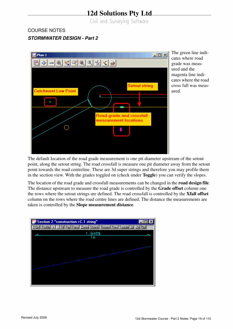
Verification strings in the same model confirm the locations where the road grade and crossfall have
been measured. To check these strings add the construction drainage data model to the plan view.
The following image shows a close up of the verification strings at a pit.
Revised July 2008 12d Stormwater Course - Part 2 Notes: Page 19 of 110
12d Solutions Pty Ltd
COURSE NOTES
STORMWATER DESIGN - Part 2
The default location of the road grade measurement is one pit diameter upstream of the setout
point, along the setout string. The road crossfall is measure one pit diameter away from the setout
point towards the road centreline. These are 3d super strings and therefore you may profile them
in the section view. With the grades toggled on (check under Toggle) you can verify the slopes.
The location of the road grade and crossfall measurements can be changed in the road design file.
The distance upstream to measure the road grade is controlled by the Grade offset column one
the rows where the setout strings are defined. The road crossfall is controlled by the Xfall offset
column on the rows where the road centre lines are defined. The distance the measurements are
taken is controlled by the Slope measurement distance.
The green line indi-
cates where road
grade was meas-
ured and the
magenta line indi-
cates where the road
cross fall was meas-
ured.

Revised July 200812d Stormwater Course - Part 2 Notes: Page 20 of 110
12d Solutions Pty Ltd
COURSE NOTES
STORMWATER DESIGN - Part 2
Important Notes
1. Pits with no inlet capacity defined will have a zero inlet capacity.
2. Manholes have no inlet capacity.
3. If no bypass flow string is supplied for a pit, the inlet capacity is set to 100%.
4. If you have a problem with the inlet capacity factors (Drains Version 1 and ILSAX), check the
calculated crossfall and grade.
Revised July 2008 12d Stormwater Course - Part 2 Notes: Page 21 of 110
12d Solutions Pty Ltd
COURSE NOTES
STORMWATER DESIGN - Part 2
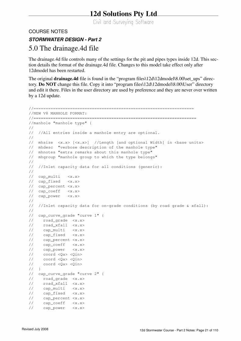
5.0 The drainage.4d file
The drainage.4d file controls many of the settings for the pit and pipes types inside 12d. This sec-
tion details the format of the drainage.4d file. Changes to this model take effect only after
12dmodel has been restarted.
The original drainage.4d file is found in the “program files\12d\12dmodel\8.00\set_ups” direc-
tory. Do NOT change this file. Copy it into “program files\12d\12dmodel\8.00\User” directory
and edit it there. Files in the user directory are used by preference and they are never over written
by a 12d update.
//==================================================================
//NEW V8 MANHOLE FORMAT:
//===================================================================
//manhole "manhole type" {
//
// //All entries inside a manhole entry are optional.
//
// mhsize <x.x> [<x.x>] //Length [and optional Width] in <base units>
// mhdesc "verbose description of the manhole type"
// mhnotes "extra remarks about this manhole type"
// mhgroup "manhole group to which the type belongs"
//
// //Inlet capacity data for all conditions (generic):
//
// cap_multi <x.x>
// cap_fixed <x.x>
// cap_percent <x.x>
// cap_coeff <x.x>
// cap_power <x.x>
//
// //Inlet capacity data for on-grade conditions (by road grade & xfall):
//
// cap_curve_grade "curve 1" {
// road_grade <x.x>
// road_xfall <x.x>
// cap_multi <x.x>
// cap_fixed <x.x>
// cap_percent <x.x>
// cap_coeff <x.x>
// cap_power <x.x>
// coord <Qa> <Qin>
// coord <Qa> <Qin>
// coord <Qa> <Qin>
// }
// cap_curve_grade "curve 2" {
// road_grade <x.x>
// road_xfall <x.x>
// cap_multi <x.x>
// cap_fixed <x.x>
// cap_percent <x.x>
// cap_coeff <x.x>
// cap_power <x.x>
Revised July 200812d Stormwater Course - Part 2 Notes: Page 22 of 110
12d Solutions Pty Ltd
COURSE NOTES
STORMWATER DESIGN - Part 2
// coord <Qa> <Qin>
// coord <Qa> <Qin>
// coord <Qa> <Qin>
// }
// cap_curve_grade "curve n" {
// road_grade <x.x>
// road_xfall <x.x>
// cap_multi <x.x>
// cap_fixed <x.x>
// cap_percent <x.x>
// cap_coeff <x.x>
// cap_power <x.x>
// coord <Qa> <Qin>
// coord <Qa> <Qin>
// coord <Qa> <Qin>
// }
//
// //Inlet capacity data for sag conditions:
//
// cap_curve_sag "curve sag" {
// cap_multi <x.x>
// cap_fixed <x.x>
// cap_percent <x.x>
// cap_coeff <x.x>
// cap_power <x.x>
// coord <Depth> <Qin>
// coord <Depth> <Qin>
// coord <Depth> <Qin>
// }
//}
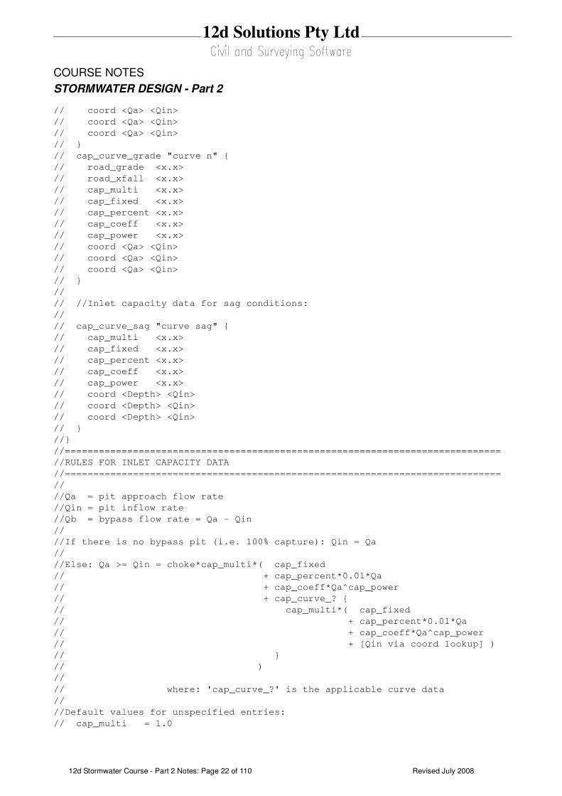
//=============================================================================
//RULES FOR INLET CAPACITY DATA
//=============================================================================
//
//Qa = pit approach flow rate
//Qin = pit inflow rate
//Qb = bypass flow rate = Qa - Qin
//
//If there is no bypass pit (i.e. 100% capture): Qin = Qa
//
//Else: Qa >= Qin = choke*cap_multi*( cap_fixed
// + cap_percent*0.01*Qa
// + cap_coeff*Qa^cap_power
// + cap_curve_? {
// cap_multi*( cap_fixed
// + cap_percent*0.01*Qa
// + cap_coeff*Qa^cap_power
// + [Qin via coord lookup] )
// }
// )
//
// where: 'cap_curve_?' is the applicable curve data
//
//Default values for unspecified entries:
// cap_multi = 1.0
Revised July 2008 12d Stormwater Course - Part 2 Notes: Page 23 of 110
12d Solutions Pty Ltd
COURSE NOTES
STORMWATER DESIGN - Part 2
// cap_fixed = 0.0
// cap_percent = 0.0
// cap_coeff = 0.0
// cap_power = 1.0
//
//Rules for 'cap_curve_grade' entries:
// *Only applicable to on-grade pits.
// *All cap_curve_grade entries must be uniquely named within a pit.
// *The 'road_grade' and 'road_xfall' entries are both optional, but their
// use must be consistent across all cap_curve_grade entries within a pit.
// *If both 'road_grade' and 'road_xfall' entries are omitted, only one
// cap_curve_grade entry is allowed within a pit.
// *The 'road_grade' and 'road_xfall' entries must be specified in %, and are
// interpreted as minimum threshold values.
// *The cap_curve_grade 'coord' entries (if used) must be in order of
// increasing Qa.
//
//Rules for 'cap_curve_sag' entries:
// *Only applicable to sag pits.
// *Only one cap_curve_sag entry is allowed within a pit, and it must have
// a valid name.
// *The cap_curve_sag 'coord' entries (if used) must be in order of
// increasing Depth.
// *It is recommended that all sag pits have 'coord' entries, because even
// if there is no bypass pit (100% capture), the 'coord' entries are used
// to reverse-calculate the flooded depth at the sag inlet, based on Qin.
//
//NB1: Flow rates must be specified in "cubic <base units> per second".
//NB2: Depths must be specified in <base units>.
//
//
=============================================================================
5.1 Pit Inlet Capacities
The pit inlet capacity tables contained within the drainage.4d file are used by the drainage design
packages in different ways but with a common philosophy.
5.1.1 On grade pits
The grade and crossfall values for the tables are threshold values, i.e. the next set of capacity fac-
tors will not be used until the crossfall and grade are equal to or exceed the values for the curves.
The curves are not interpolated!
12d Storm Analysis
Some sample Pit definitions follow to demonstrate how the pit inlet capacities are calculated.
Revised July 200812d Stormwater Course - Part 2 Notes: Page 24 of 110
12d Solutions Pty Ltd
COURSE NOTES
STORMWATER DESIGN - Part 2
Manhole "SEP 25" {
mhsize 1.200 0.900
mhdesc "SEP with 25 l/s"
mhnotes ""
mhgroup "SA"
cap_multi 1.0
cap_fixed 0.025
}
Manhole "SEP 50 percent" {
mhsize 1.200 0.900
mhdesc "SEP with 50%"
mhnotes ""
mhgroup "SA"
cap_multi 1.0
cap_percent 50.
}
Manhole "SEP Grade x 10" {
mhsize 1.200 0.900
mhdesc "SEP with 25 l/s"
mhnotes ""
mhgroup "SA"
cap_curve_grade "curve 1" {
road_grade 1
cap_multi 1.0
cap_fixed 0.010
}
cap_curve_grade "curve 2" {
road_grade 2
cap_multi 1.0
cap_fixed 0.020
}
cap_curve_grade "curve 3" {
road_grade 3
cap_multi 1.0
cap_fixed 0.030
}
cap_curve_sag "curve sag" {
Revised July 2008 12d Stormwater Course - Part 2 Notes: Page 25 of 110
12d Solutions Pty Ltd
COURSE NOTES
STORMWATER DESIGN - Part 2
cap_multi 1.0
coord 0.0 0.000
coord 0.1 0.010
}
}
Drains Version 1 and ILSAX
The cap1, cap2, cap3 and cap4 values are used to describe the inlet capacity of the pit as described
in their user manuals.
Drains Version +
The 12d inlet curve names are exported to Drains as the pit family.
xpswmm, xpstorm and RAT-HGL
If cap2, cap3 and cap4 are all equal to zero then a fixed inlet capacity equal to cap1 will be
exported to RAT-HGL. If the sum of these three values is greater than zero then a pit type will be
created in the format of pit_type-crossfall-roadgrade. For example SA2-3-2 for a SA2 pit with a
road crossfall of 3% and a road grade of 2%. A rating curve with this name will have to exist
inside RAT-HGL. 12d has no way of transferring the rating curve itself into RAT-HGL.
PC Drain
Similar to RAT-HGL, PC Drain has it own rating curves defined internally. The road grade is sent
as a separate piece of data to PC Drain so that the pit inlet capacity may be determined.
5.1.2 SAG Inlets
PC Drain
PC Drain places a suffix code in the pit type to specify that the pit is a SAG pit. For example an
9S.03 indicates that pit type 9 is a sag pit and the maximum depth before bypassing is 30mm.
Revised July 200812d Stormwater Course - Part 2 Notes: Page 26 of 110
12d Solutions Pty Ltd
COURSE NOTES
STORMWATER DESIGN - Part 2
6.0 12d Storm Analysis Bypass and Flooded Width Calculations
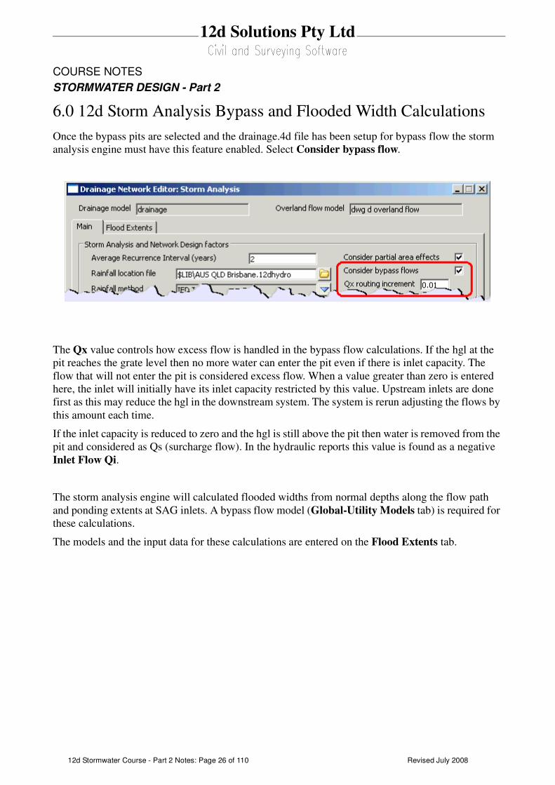
Once the bypass pits are selected and the drainage.4d file has been setup for bypass flow the storm
analysis engine must have this feature enabled. Select Consider bypass flow.
The Qx value controls how excess flow is handled in the bypass flow calculations. If the hgl at the
pit reaches the grate level then no more water can enter the pit even if there is inlet capacity. The
flow that will not enter the pit is considered excess flow. When a value greater than zero is entered
here, the inlet will initially have its inlet capacity restricted by this value. Upstream inlets are done
first as this may reduce the hgl in the downstream system. The system is rerun adjusting the flows by
this amount each time.
If the inlet capacity is reduced to zero and the hgl is still above the pit then water is removed from the
pit and considered as Qs (surcharge flow). In the hydraulic reports this value is found as a negative
Inlet Flow Qi.
The storm analysis engine will calculated flooded widths from normal depths along the flow path
and ponding extents at SAG inlets. A bypass flow model (Global-Utility Models tab) is required for
these calculations.
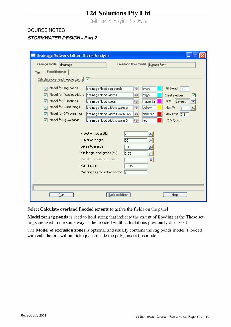
The models and the input data for these calculations are entered on the Flood Extents tab.
Revised July 2008 12d Stormwater Course - Part 2 Notes: Page 27 of 110
12d Solutions Pty Ltd
COURSE NOTES
STORMWATER DESIGN - Part 2
Select Calculate overland flooded extents to active the fields on the panel.
Model for sag ponds is used to hold string that indicate the extent of flooding at the These set-
tings are used in the same way as the flooded width calculations previously discussed.
The Model of exclusion zones is optional and usually contains the sag ponds model. Flooded
with calculations will not take place inside the polygons in this model.

Revised July 200812d Stormwater Course - Part 2 Notes: Page 28 of 110
12d Solutions Pty Ltd
COURSE NOTES
STORMWATER DESIGN - Part 2
7.0 Major Flood Events
If you want to keep the results for the minor and the major event then create a copy of your drainage
network and add a suffix to the model name. Select File IO->Data Output->12da/4da data.
Now read the same file into 12d using a suffix 100. Select File IO->Data Input->12da/4da data.
Use the DNW to select the new drainage 100 model.
For major flood events the user may desire to use an alternative set of values for
Catchment tc,
Catchment C,
Pit direct inflow (Qdi),
Pipe direct inflow (Qpi),
Revised July 2008 12d Stormwater Course - Part 2 Notes: Page 29 of 110
12d Solutions Pty Ltd
COURSE NOTES
STORMWATER DESIGN - Part 2
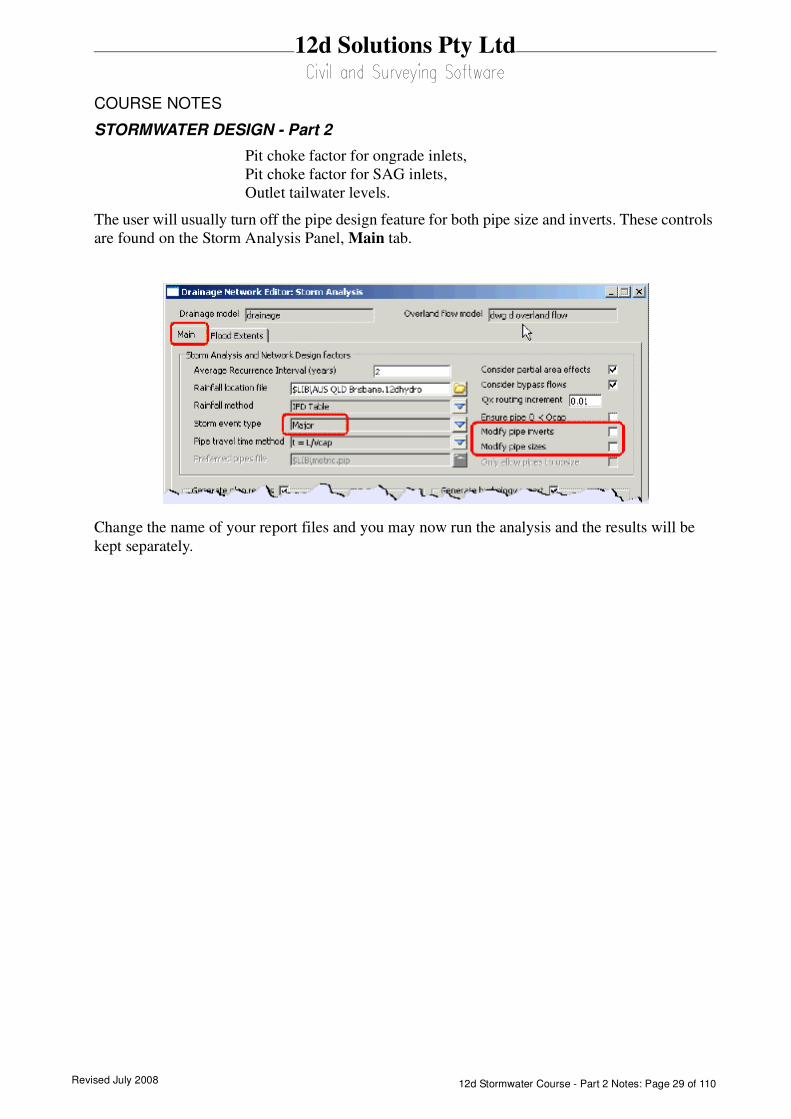
Pit choke factor for ongrade inlets,
Pit choke factor for SAG inlets,
Outlet tailwater levels.
The user will usually turn off the pipe design feature for both pipe size and inverts. These controls
are found on the Storm Analysis Panel, Main tab.
Change the name of your report files and you may now run the analysis and the results will be
kept separately.
Revised July 200812d Stormwater Course - Part 2 Notes: Page 30 of 110
12d Solutions Pty Ltd
COURSE NOTES
STORMWATER DESIGN - Part 2
8.0 Open Channel Flow
12d can model flow in open channels a trapezoidal sections. Suggestions for drainage network editor
settings are listed below.
Key points
The pit grate level must always be at or above the top of the open channel conduit.
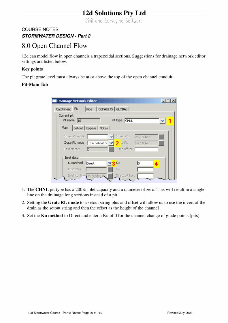
Pit-Main Tab
1. The CHNL pit type has a 200% inlet capacity and a diameter of zero. This will result in a single
line on the drainage long sections instead of a pit.
2. Setting the Grate RL mode to a setout string plus and offset will allow us to use the invert of the
drain as the setout string and then the offset as the height of the channel
3. Set the Ku method to Direct and enter a Ku of 0 for the channel change of grade points (pits).

Revised July 2008 12d Stormwater Course - Part 2 Notes: Page 31 of 110
12d Solutions Pty Ltd
COURSE NOTES
STORMWATER DESIGN - Part 2
Pit-Setout Tab
4. Enter the Sz equal to the height of the channel. This will set the grate level at the top of the
channel.
Revised July 200812d Stormwater Course - Part 2 Notes: Page 32 of 110
12d Solutions Pty Ltd
COURSE NOTES
STORMWATER DESIGN - Part 2
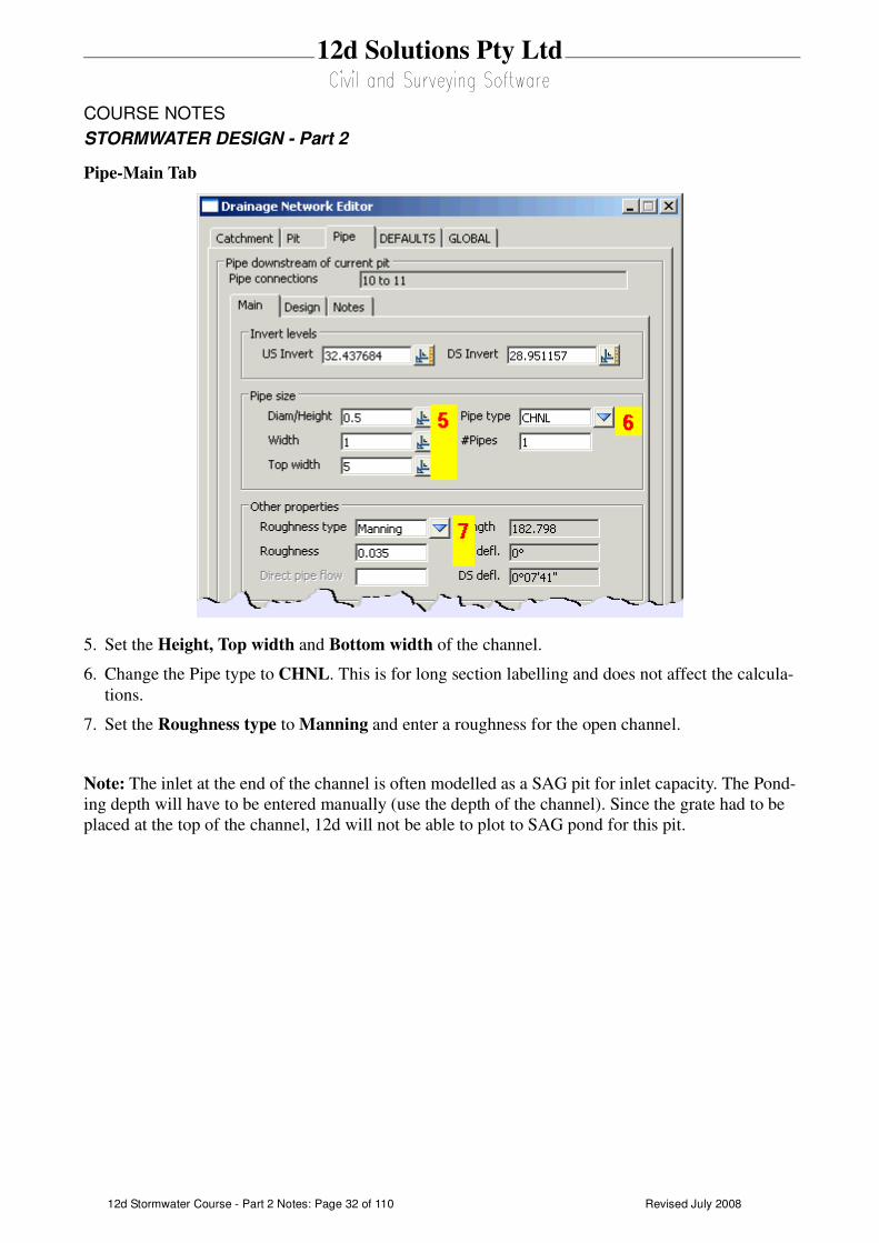
Pipe-Main Tab
5. Set the Height, Top width and Bottom width of the channel.
6. Change the Pipe type to CHNL. This is for long section labelling and does not affect the calcula-
tions.
7. Set the Roughness type to Manning and enter a roughness for the open channel.
Note: The inlet at the end of the channel is often modelled as a SAG pit for inlet capacity. The Pond-
ing depth will have to be entered manually (use the depth of the channel). Since the grate had to be
placed at the top of the channel, 12d will not be able to plot to SAG pond for this pit.
Revised July 2008 12d Stormwater Course - Part 2 Notes: Page 33 of 110
12d Solutions Pty Ltd
COURSE NOTES
STORMWATER DESIGN - Part 2
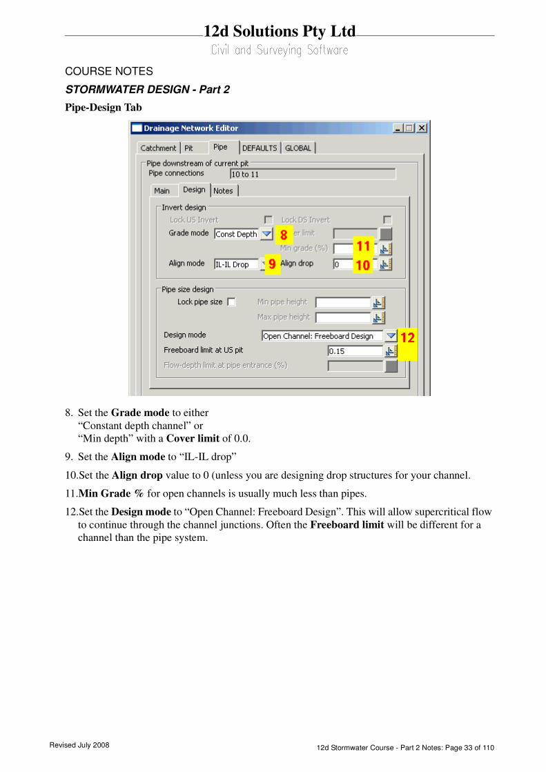
Pipe-Design Tab
8. Set the Grade mode to either
“Constant depth channel” or
“Min depth” with a Cover limit of 0.0.
9. Set the Align mode to “IL-IL drop”
10.Set the Align drop value to 0 (unless you are designing drop structures for your channel.
11.Min Grade % for open channels is usually much less than pipes.
12.Set the Design mode to “Open Channel: Freeboard Design”. This will allow supercritical flow
to continue through the channel junctions. Often the Freeboard limit will be different for a
channel than the pipe system.

Revised July 200812d Stormwater Course - Part 2 Notes: Page 34 of 110
12d Solutions Pty Ltd
COURSE NOTES
STORMWATER DESIGN - Part 2
9.0 Excavation Quantities
Sample templates are included in the courses section of 12djobs (\12djobs\courses\8.00\drain-
age\pipe template.tpl). The templates from this template library may be added to your project using
Design=>Templates=>Utilities=>Input.
This routine uses 12d templates to calculate the excavation volume for all of the drainage strings in a
model. An option to create section for a tin on top of the pipe is also available so that the drainage
long sections can include hatching between the obvert of the pipe and the design tin under roads.
Templates with names set to the pipe diameters (times 1000) are used for the calculations, thus
trench shapes can be customised and over excavation for bedding materials can be included. Net area
calculations to exclude pipe area are not supported.
Key points
1. One template for each pipe size (mm)
2. If obvert templates are used, add the prefix “obvert “ to the pipe size
3. Carefully consider the tin selected.
A template must exist for each pipe size in the model (pipe size x 1000). For example a 0.3m pipe
will require a template to exist named 300. A 0.5ft pipe would require a template named 500. Sample
templates are included in the courses section of 12djobs (\12djobs\courses\7.00\drainage). These
may be copied to your *.project directory and then added to your project using Design=>Tem-
plates=>Utilities=>Add=>All all to project.
The templates are run along the strings and the total volumes are reported. Volumes for each strings
are given in the report file. An example follows.
----------------------------- BEGIN APPLY TEMPLATE REPORT ------------------------------
apply template to string report -
string E
tin design
separation 10.000
left template 375
right template 375
cut volumes and areas are negative
fill volumes and areas are positive
chainage- ------sectional information------ ------intermediate information---- ---------accumulative information-------
---------- ---cut area --fill area ------------ ----cut vol ---fill vol -cut volume-- -fill volume- ---balance---
0.000 -1.434 0.000 0.000 0.000 0.000
-0.771 0.000
0.550 -1.367 0.000 -0.771 0.000 -0.771
-14.222 0.000
10.000 -1.642 0.000 -14.992 0.000 -14.992
-15.293 0.000
20.000 -1.416 0.000 -30.286 0.000 -30.286
-1.845 0.000
21.313 -1.393 0.000 -32.130 0.000 -32.130
-0.794 0.000
21.863 -1.493 0.000 -32.924 0.000 -32.924
total cut -32.924
total fill 0.000
balance -32.924
ie excess of cut over fill 32.924
----------------------------- END APPLY TEMPLATE REPORT ------------------------------
Revised July 2008 12d Stormwater Course - Part 2 Notes: Page 35 of 110
12d Solutions Pty Ltd
COURSE NOTES
STORMWATER DESIGN - Part 2
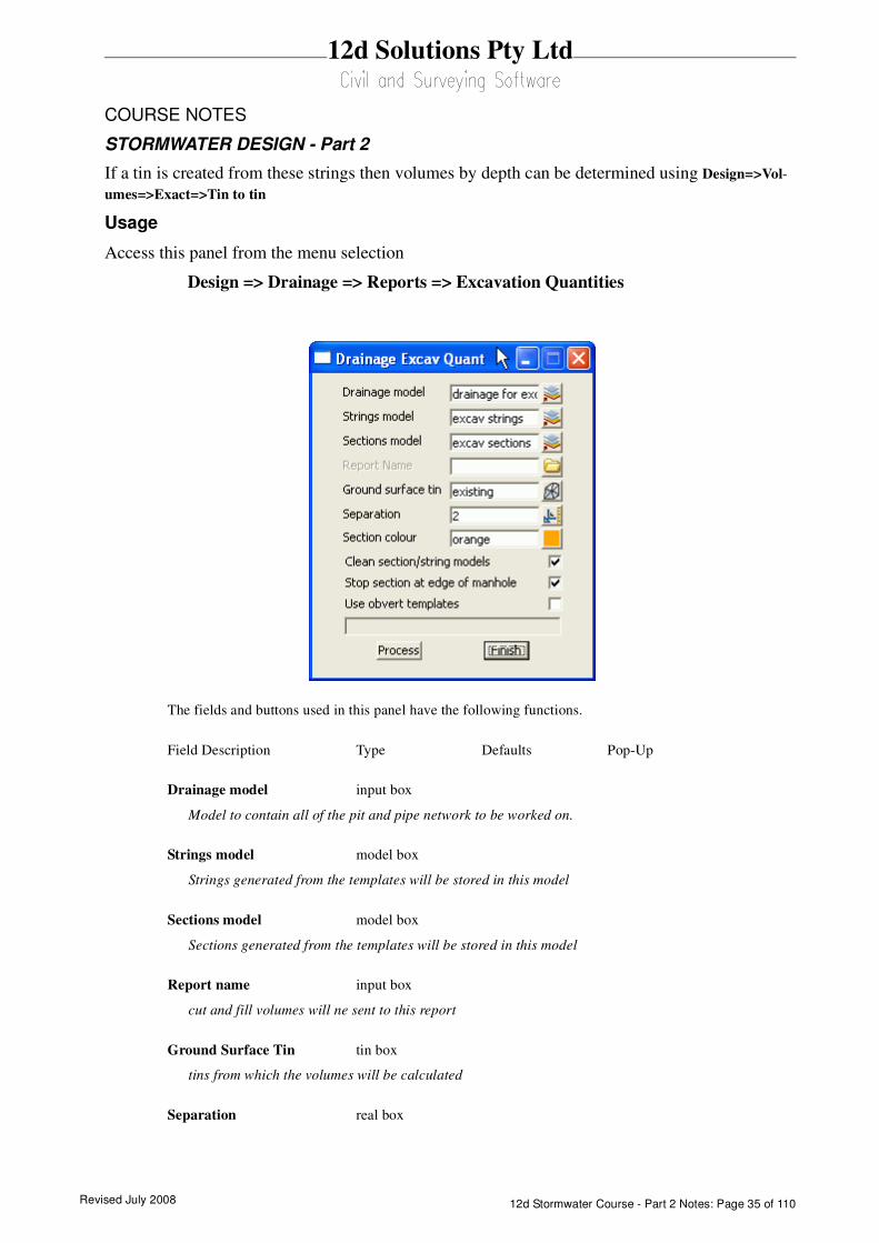
If a tin is created from these strings then volumes by depth can be determined using Design=>Vol-
umes=>Exact=>Tin to tin
Usage
Access this panel from the menu selection
Design => Drainage => Reports => Excavation Quantities
The fields and buttons used in this panel have the following functions.
Field Description Type Defaults Pop-Up
Drainage model input box
Model to contain all of the pit and pipe network to be worked on.
Strings model model box
Strings generated from the templates will be stored in this model
Sections model model box
Sections generated from the templates will be stored in this model
Report name input box
cut and fill volumes will ne sent to this report
Ground Surface Tin tin box
tins from which the volumes will be calculated
Separation real box
Revised July 200812d Stormwater Course - Part 2 Notes: Page 36 of 110
12d Solutions Pty Ltd
COURSE NOTES
STORMWATER DESIGN - Part 2
distance between the sections
Sections colour colour box
Sections generated from the templates will be assigned this colour (strings colours are defined in the tem-
plates)
Clean section/strings model tick box
Delete the strings in these models before processing.
Stop section at edge of pit tick box
Template are run from pit centre to centre if this is not selected. The templates stop at the edge of the pit if
selected. This is often selected with the following option Use obvert templates.
Use obvert templates tick box
Templates must be named with the prefix “obvert”. i.e. obvert 300. The template is still run along the
invert of the pipe but the user now has a section “set” of templates that can be used to create a tin on top
of the pipe as well as below.
Revised July 2008 12d Stormwater Course - Part 2 Notes: Page 37 of 110
12d Solutions Pty Ltd
COURSE NOTES
STORMWATER DESIGN - Part 2
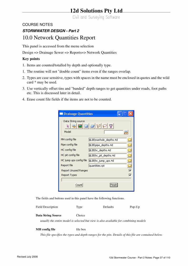
10.0 Network Quantities Report
This panel is accessed from the menu selection
Design => Drainage Sewer => Reports=> Network Quantities
Key points
1. Items are counted/totalled by depth and optionally type.
1. The routine will not "double count" items even if the ranges overlap.
2. Types are case sensitive, types with spaces in the name must be enclosed in quotes and the wild
card * may be used.
3. Use vertically offset tins and "banded" depth ranges to get quantities under roads, foot paths
etc. This is discussed later in detail.
4. Erase count file fields if the items are not to be counted.
The fields and buttons used in this panel have the following functions.
Field Description Type Defaults Pop-Up
Data String Source Choice
usually the entire model is selected but view is also available for combining models
MH config file file box
This file specifies the types and depth ranges for the pits. Details of this file are contained below.
Revised July 200812d Stormwater Course - Part 2 Notes: Page 38 of 110
12d Solutions Pty Ltd
COURSE NOTES
STORMWATER DESIGN - Part 2
Pipe config file file box
This file specifies the types and depth ranges for the pipes. Details of this file are contained below.
HC config file file box
This file specifies the types and depth ranges for the house connections. Details of this file are contained
below.
HC pit config file file box
This file specifies the types and depth ranges for the HC pits. Details of this file are contained below.
HC jump ups file file box
This file specifies the types and depth ranges for the house connections jump ups. Details of this file are
contained below.
Report file file box
a sample report file is given below.
Report unused ranges tick box
the depth ranges for the pit/pipe/house connections are defined in the *.4d files. Selecting this option will
cause the depth ranges in the file to be printed even if there are no pit/pipe/house connections in these
depth ranges (zero quantity values will be shown).
Report types tick box
Selecting this option will cause the pit/pipe/house connection types used in the model types to be listed
(even if quantities are not requested in the *.4d files). Since this is a complete of the type used in the model,
the list informs the user what types have not been included in the quantity calculation.
Count button
executes the option.
Finish button
removes the dialogue from the screen
The *.4d files listed above are contained in the 12d library directory. Each line is the file performs a
count (count lines). No items are counted twice. Therefore, if an item is counted its type and then a
count line is found the wild card is used for the type, the type already counted will not be included in
the count.
The format for a count line is three or four values (space delimited) per line. Size is optional.
<type (from drainage.4d)> <size> <starting depth> <ending depth>
Notes:
Revised July 2008 12d Stormwater Course - Part 2 Notes: Page 39 of 110
12d Solutions Pty Ltd
COURSE NOTES
STORMWATER DESIGN - Part 2
All types with spaces in the name must be enclosed in quotes The wild card * may be used.
The size is optional and if omitted the all sizes will be counted in this group (do not use the * for a
wild card).
The starting depth and ending depth are required for all count lines.
Quantities Under Roads and Footpaths
By creating super tins with vertically offset sections, quantities under roads, footpaths etc. can be
determined. for example.
Offset your road design tin up by 1000m (Tins->Utility->Translate/Copy) and then use the
depth range 1000-1999 for pipes under roads.
Create a tin from the footpaths only, null by angle length with a small length to remove the road
and then offset it vertically by 2000m. the depth range 2000-2999 is not the quantities under the
footpath.
Sample count lines
// sum concrete cover manholes is various ranges
"CONC COVER" 0.0 1.6
"CONC COVER" 1.5 3.0
"CONC COVER" 3.0 999.9 // this is expected to be zero
"CONC COVER" -999.0 0.0 // trap errors
// any that are not Concrete cover will be counted here
* 0.0 1.6
* 1.6 3.0
* 3.0 999.9
Revised July 200812d Stormwater Course - Part 2 Notes: Page 40 of 110
12d Solutions Pty Ltd
COURSE NOTES
STORMWATER DESIGN - Part 2
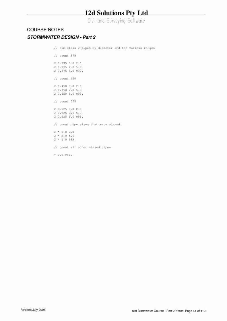
Sample count lines for pipes follow.
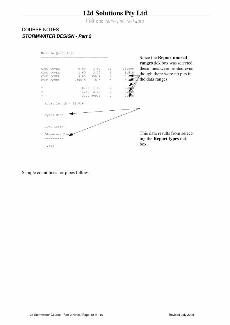
Manhole Quantities
====================================
CONC COVER 0.00 1.60 13 16.506
CONC COVER 1.60 3.00 1 1.510
CONC COVER 3.00 999.9 0 0.000
CONC COVER -999.0 0.0 0 0.000
* 0.00 1.60 0 0.000
* 1.60 3.00 0 0.000
* 3.00 999.9 0 0.000
total length = 18.016
Types Used
----------
CONC COVER
Diameters Used
----------
1.100
Since the Report unused
ranges tick box was selected,
these lines were printed even
though there were no pits in
the data ranges.
This data results from select-
ing the Report types tick
box.
Revised July 2008 12d Stormwater Course - Part 2 Notes: Page 41 of 110
12d Solutions Pty Ltd
COURSE NOTES
STORMWATER DESIGN - Part 2
// sum class 2 pipes by diameter and for various ranges
// count 375
2 0.375 0.0 2.0
2 0.375 2.0 5.0
2 0.375 5.0 999.
// count 450
2 0.450 0.0 2.0
2 0.450 2.0 5.0
2 0.450 5.0 999.
// count 525
2 0.525 0.0 2.0
2 0.525 2.0 5.0
2 0.525 5.0 999.
// count pipe sizes that were missed
2 * 0.0 2.0
2 * 2.0 5.0
2 * 5.0 999.
// count all other missed pipes
* 0.0 999.

Revised July 200812d Stormwater Course - Part 2 Notes: Page 42 of 110
12d Solutions Pty Ltd
COURSE NOTES
STORMWATER DESIGN - Part 2
11.0 Exporting to Drainage Design Software Packages
12d contains most of the data required for your drainage design packages. However, each packages
has specific design variables that 12d does not have access too. The design process is intended to
export your data from 12d to the design package, design the drainage system and then read the
results back into 12d for your long sections.
If pits/pipes are to be added/deleted from your network during the design process you are safest to
add/delete the pit/pipe to 12d and to your design package separately.
Not recommended and as a poor alternative, you have the option of reading the results back into 12d,
adding/deleting the pits/pipes and then exporting the data to a new drainage project in your drainage
design software. As 12d does not have access to all of the data in the design packages this
method is not recommended!
Some of the drainage design programs offer a third option that allows you to import data “on top of”
an existing project thereby merging and over writing the existing data. Be sure to contact the drain-
age software supplier to obtain exact details of how the merging process is performed.
The interface is run by selecting Import/Export from the Drainage Network Editor
Design->Drainage-Sewer->Network Editor
Revised July 2008 12d Stormwater Course - Part 2 Notes: Page 43 of 110
12d Solutions Pty Ltd
COURSE NOTES
STORMWATER DESIGN - Part 2
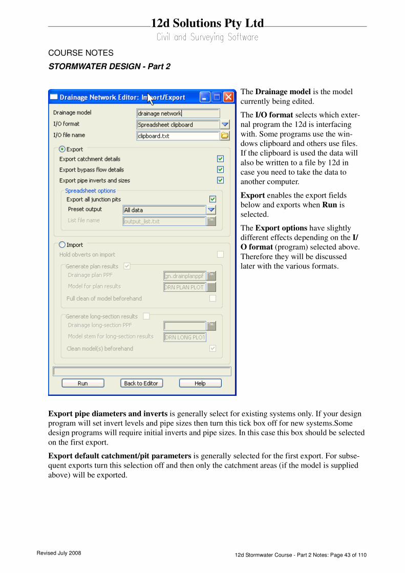
Export pipe diameters and inverts is generally select for existing systems only. If your design
program will set invert levels and pipe sizes then turn this tick box off for new systems.Some
design programs will require initial inverts and pipe sizes. In this case this box should be selected
on the first export.
Export default catchment/pit parameters is generally selected for the first export. For subse-
quent exports turn this selection off and then only the catchment areas (if the model is supplied
above) will be exported.
The Drainage model is the model
currently being edited.
The I/O format selects which exter-
nal program the 12d is interfacing
with. Some programs use the win-
dows clipboard and others use files.
If the clipboard is used the data will
also be written to a file by 12d in
case you need to take the data to
another computer.
Export enables the export fields
below and exports when Run is
selected.
The Export options have slightly
different effects depending on the I/
O format (program) selected above.
Therefore they will be discussed
later with the various formats.

Revised July 200812d Stormwater Course - Part 2 Notes: Page 44 of 110
12d Solutions Pty Ltd
COURSE NOTES
STORMWATER DESIGN - Part 2
12.0 Drainage Data Input and Output to Spreadsheets
Spreadsheets are an effective method to manage the numerous variables urban drainage designers
create in the modelling process. Spreadsheet data can be transferred to and from 12d in tab delimited
files and stored within 12d as “user definable attributes”. These attributes are linked to the pit and
pipes within a network. Drainage long section plots can display the pipe attributes in the “arrows”
data area and pit attributes in the bubbles area. Drainage plan drawing can also show these pit and
pipe attributes.
Drainage strings will be created if they do not exist in the model but pits cannot be added to existing
strings.
See also
12d to spreadsheet transfers
Spreadsheet to 12d update and create
Spreadsheet options
12.1 12d to spreadsheet transfers
This interface is accessed the Import/Export button on the Drainage Network Editor.
Revised July 2008 12d Stormwater Course - Part 2 Notes: Page 45 of 110
12d Solutions Pty Ltd
COURSE NOTES
STORMWATER DESIGN - Part 2
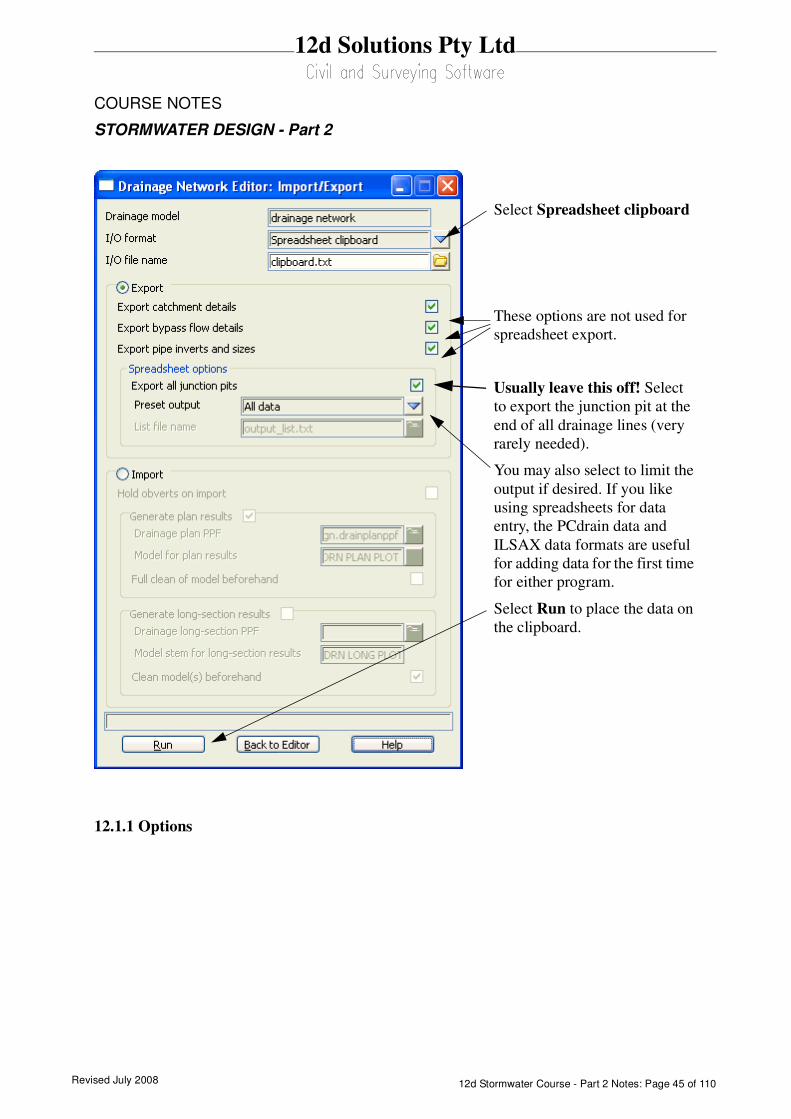
12.1.1 Options
Select Spreadsheet clipboard
These options are not used for
spreadsheet export.
Usually leave this off! Select
to export the junction pit at the
end of all drainage lines (very
rarely needed).
You may also select to limit the
output if desired. If you like
using spreadsheets for data
entry, the PCdrain data and
ILSAX data formats are useful
for adding data for the first time
for either program.
Select Run to place the data on
the clipboard.

Revised July 200812d Stormwater Course - Part 2 Notes: Page 46 of 110
12d Solutions Pty Ltd
COURSE NOTES
STORMWATER DESIGN - Part 2
The Spreadsheet Options section allows the user to define the amount of data exported.
All Data: All of the 12d drainage string data and the user defined attributes will be exported to the
clipboard in a tab delimited format. The 12d data names and the user defined attribute names will
appear at the top of the spreadsheets columns.
ILSAX: For the ILSAX program, the spreadsheet column headings will change depending on the
pipe and catchment indicators (P2 card) and the inlet type (P3 card). Therefore, use the ILSAX pipe
editor macro to set up one pit/catchment for the type of data you wish to enter. Now when you export
the pipe network data the column headings will include the names of the relevant parameters.
User defined below: The Customised list file name is used to define the drainage values, their
order and format you desire.
The customised list file is a text file where each line contains a drainage variable or a spreadsheet IO
command (blank lines are ignored unless preceded by the header command). The spreadsheet IO
commands are all lower case and listed below:
header to define a line of text to be exported
blank to leave a blank column in the output
pit data the following attributes are for the pit.
downstream pit data the following attributes are for the downstream pit.
upstream pit data the following attributes are for the upstream pit(s).
pipe data the following attributes are for the pit’s outlet pipe
downstream pipe data the following attributes are for the downstream pipe(s)
upstream pipe data the following attributes are for the upstream pipe(s)
variable name a 12d drainage variable names
factor the following variable is multiplied by this factor
decimals the following variable will export with these decimal places
The simplest way to create your own customised tab delimited file is to set the Preset Output field
Export all junction pits
when selected will repeat
the data for the junction
pit at the end of each
branch line.
Preset Output this
choice box offers the fol-
lowing choices:
Revised July 2008 12d Stormwater Course - Part 2 Notes: Page 47 of 110
12d Solutions Pty Ltd
COURSE NOTES
STORMWATER DESIGN - Part 2
to All data and leave the customised list file name field blank. Selecting Set, Finish and then
Copy from the main dialogue. The data will be placed on the clipboard and a customised list file,
named output_list.txt will be created containing the names of all of the drainage variables in the
12d model. Use a text editor to add/or delete the variable names, change their order and/or add
spreadsheet IO commands. Save the file with a new name! The output_list.txt file is overwitten
on every export.
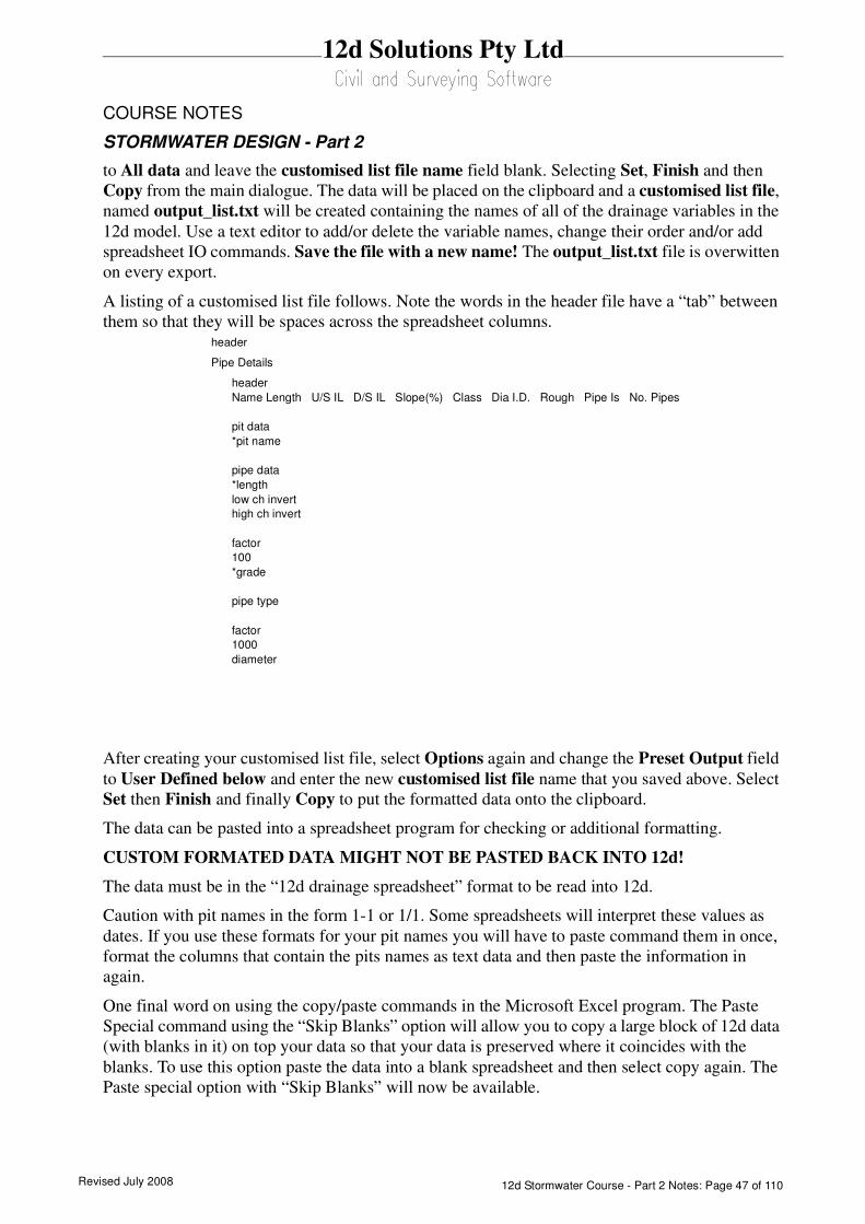
A listing of a customised list file follows. Note the words in the header file have a “tab” between
them so that they will be spaces across the spreadsheet columns.
After creating your customised list file, select Options again and change the Preset Output field
to User Defined below and enter the new customised list file name that you saved above. Select
Set then Finish and finally Copy to put the formatted data onto the clipboard.
The data can be pasted into a spreadsheet program for checking or additional formatting.
CUSTOM FORMATED DATA MIGHT NOT BE PASTED BACK INTO 12d!
The data must be in the “12d drainage spreadsheet” format to be read into 12d.
Caution with pit names in the form 1-1 or 1/1. Some spreadsheets will interpret these values as
dates. If you use these formats for your pit names you will have to paste command them in once,
format the columns that contain the pits names as text data and then paste the information in
again.
One final word on using the copy/paste commands in the Microsoft Excel program. The Paste
Special command using the “Skip Blanks” option will allow you to copy a large block of 12d data
(with blanks in it) on top your data so that your data is preserved where it coincides with the
blanks. To use this option paste the data into a blank spreadsheet and then select copy again. The
Paste special option with “Skip Blanks” will now be available.
header
Pipe Details
header
Name Length U/S IL D/S IL Slope(%) Class Dia I.D. Rough Pipe Is No. Pipes
pit data
*pit name
pipe data
*length
low ch invert
high ch invert
factor
100
*grade
pipe type
factor
1000
diameter
Revised July 200812d Stormwater Course - Part 2 Notes: Page 48 of 110
12d Solutions Pty Ltd
COURSE NOTES
STORMWATER DESIGN - Part 2
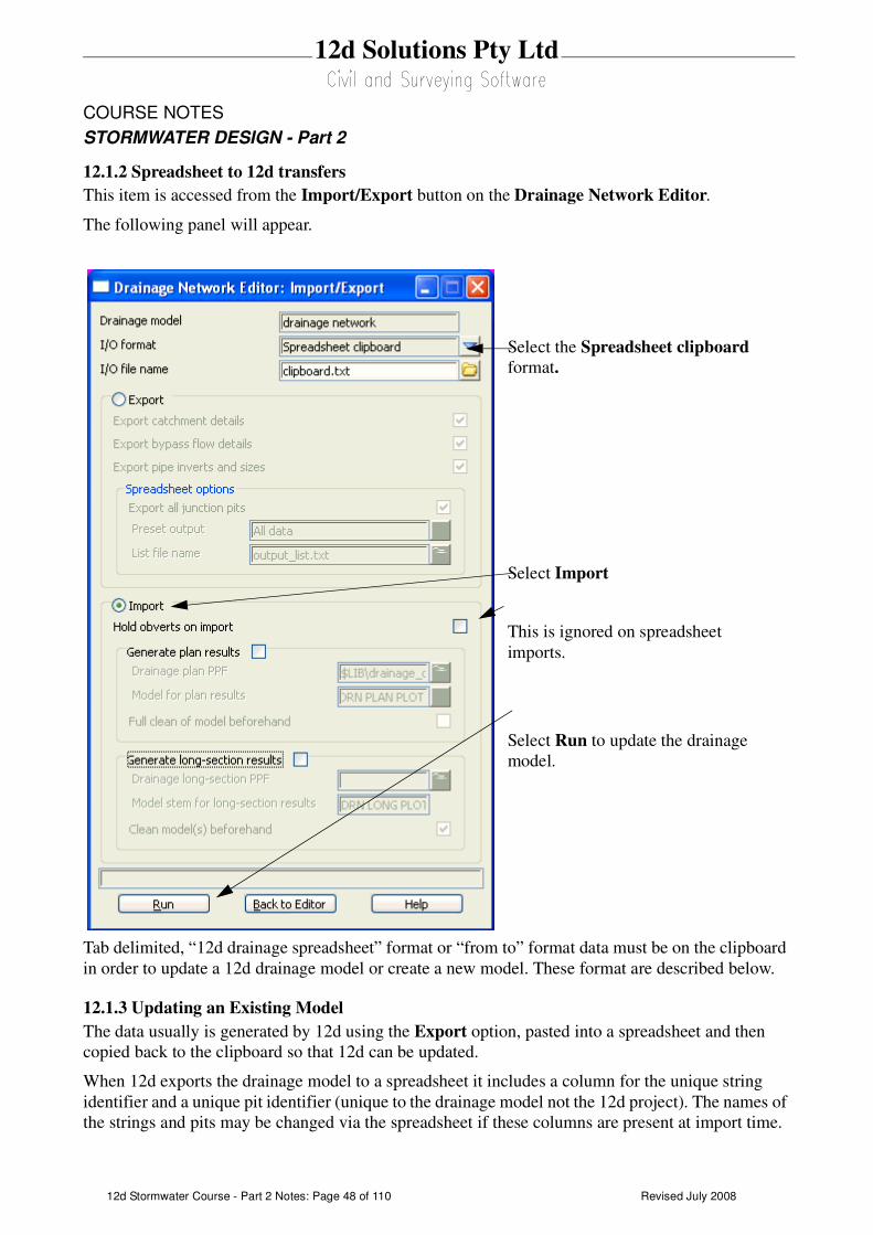
12.1.2 Spreadsheet to 12d transfers
This item is accessed from the Import/Export button on the Drainage Network Editor.
The following panel will appear.
Tab delimited, “12d drainage spreadsheet” format or “from to” format data must be on the clipboard
in order to update a 12d drainage model or create a new model. These format are described below.
12.1.3 Updating an Existing Model
The data usually is generated by 12d using the Export option, pasted into a spreadsheet and then
copied back to the clipboard so that 12d can be updated.
When 12d exports the drainage model to a spreadsheet it includes a column for the unique string
identifier and a unique pit identifier (unique to the drainage model not the 12d project). The names of
the strings and pits may be changed via the spreadsheet if these columns are present at import time.
Select the Spreadsheet clipboard
format.
Select Import
This is ignored on spreadsheet
imports.
Select Run to update the drainage
model.

Revised July 2008 12d Stormwater Course - Part 2 Notes: Page 49 of 110
12d Solutions Pty Ltd
COURSE NOTES
STORMWATER DESIGN - Part 2
If the pit id column is not present, 12d will search the drainage model for a matching pit name.
When the pit is a junction between drainage lines, only the trunk line will be the data updated.
12.1.4 Creating a New Model
It is possible to create a new string or an entire drainage network using this format. However, pits
cannot be added to an existing string. The entire drainage string must be created at once. Two for-
mats are available, the “from-to pit” format and the “12d drainage spreadsheet” format.
At present the network editor must select a drainage string to become active. Therefore, if you are
not adding strings to a network, you will have to great a drainage network with one “dummy” pit.
Select this one “dummy” pit to activate the editor. After importing the data and the new drainage
lines are created the “dummy” pit may be deleted.
12d drainage spreadsheet Format
The top left cell in the clipboard data must be the text “12d” to specify this format. The min-
imum amount of data required to create a new string is the string name, pit name, x and y
coordinates. You can add as much additional data as you have available. This would include
pipe diameters inverts etc. The pits must be listed from upstream to downstream order. If
the string is to join a trunk line, the junction pit must be included for both the tributary and
the trunk line.
An example file exists called new_network.txt is supplied in the library. Open this file in a
spreadsheet or a text editor and copy it to the clipboard. Set the I/O Action to Import and
select Run. The new drainage lines will exist in the model currently being edited.
From-to Pit Format
The top left cell in the clipboard data must be the text “from to” to specify this format. The
minimum amount of data required to create a new string is the upstream pit name "*pit
name), the downstream pit name (*ds pit name) and the x(x location) and y(y location)
coordinates of the upstream pit. If the string is to join a trunk line, the junction pit must be
included for both the tributary and the trunk line.
An optional column for the pit cover elev (cover elev) may be specified. Once the network
has been created additional pipe and pit data may be added using the “12d drainage spread-
sheet” format described above.
An example file exists called new_from_to_network.txt is supplied in the library. It is
shown below. Open this file in a spreadsheet or a text editor and copy it to the clipboard.
Enter a new model name in the Drainage model field and select paste. The new drainage
model will now exist.
Revised July 200812d Stormwater Course - Part 2 Notes: Page 50 of 110
12d Solutions Pty Ltd
COURSE NOTES
STORMWATER DESIGN - Part 2
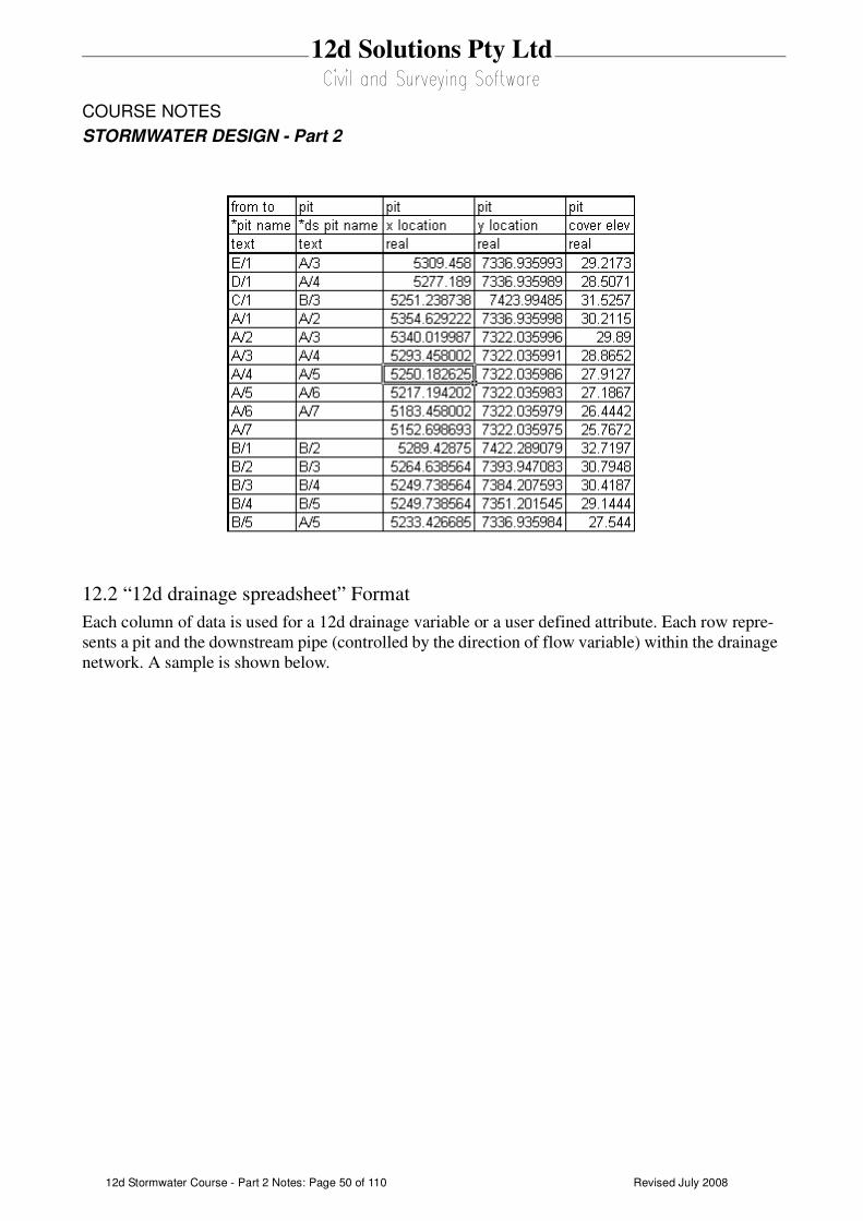
12.2 “12d drainage spreadsheet” Format
Each column of data is used for a 12d drainage variable or a user defined attribute. Each row repre-
sents a pit and the downstream pipe (controlled by the direction of flow variable) within the drainage
network. A sample is shown below.
Revised July 2008 12d Stormwater Course - Part 2 Notes: Page 51 of 110
12d Solutions Pty Ltd
COURSE NOTES
STORMWATER DESIGN - Part 2
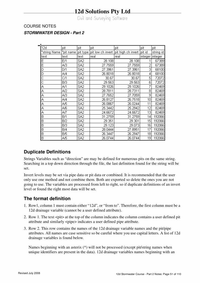
Duplicate Definitions
Strings Variables such as “direction” are may be defined for numerous pits on the same string.
Searching in a top down direction through the file, the last definition found for the string will be
set.
Invert levels may be set via pipe data or pit data or combined. It is recommended that the user
only use one method and not combine them. Both are exported so delete the ones you are not
going to use. The variables are processed from left to right, so if duplicate definitions of an invert
level or found the right most data will be set.
The format definition
1. Row1, column 1 must contain either “12d”, or “from to”. Therefore, the first column must be a
12d drainage variable (cannot be a user defined attribute).
2. Row 1. The text <pit> at the top of the column indicates the column contains a user defined pit
attribute and similarly <pipe> indicates a user defined pipe attribute.
3. Row 2. This row contains the names of the 12d drainage variable names and the pit/pipe
attributes. All names are case sensitive so be careful where you use capital letters. A list of 12d
drainage variables is found below.
Names beginning with an asterix (*) will not be processed (except pit/string names when
unique identifiers are present in the data). 12d drainage variables names beginning with an
Revised July 200812d Stormwater Course - Part 2 Notes: Page 52 of 110
12d Solutions Pty Ltd
COURSE NOTES
STORMWATER DESIGN - Part 2
asterix indicate that this data was calculated at export time and cannot be read back into 12d (for
example, pipe length, pipe grade and deflection angle).
Prefixing an user defined attribute name with “DELETE ” (no quotes, note the space after the
DELETE) will cause the attribute to be deleted from all pits/pipes within the model.
4. Row 3. The text in this row define the type of attribute to be stored within 12d. The only valid
choices are;
integer
real
text
If you want to change an attribute type you must delete the attribute and create it again. If you
simply change the attribute type in the third row then that attribute will not be updated.
5. Blank lines may be inserted as desired.
6. You are not required to fill in all of the cells in the spreadsheets. Blank cells are ignored (you must
use a space to remove all data from text attributes (the space will not be stored).
7. Pipe names are included in the data so that they can be changed but they are not used to identify
the pipe. Pipe data will always be assigned to the pipe following the pit in the direction of ascend-
ing chainage. If flow directions is ascending then the pipe data will be for the downstream pipe. If
the flow direction is descending then the pipe data will apply to the upstream pipe.
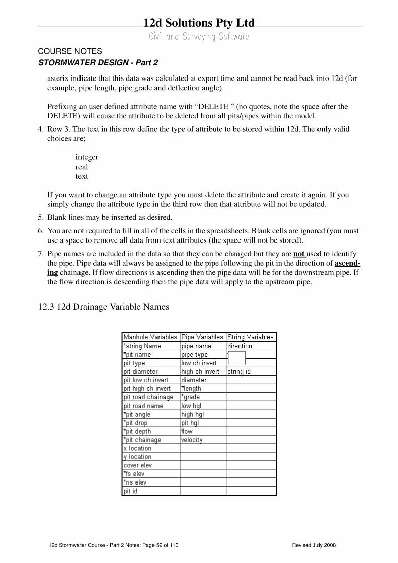
12.3 12d Drainage Variable Names

Revised July 2008 12d Stormwater Course - Part 2 Notes: Page 53 of 110
12d Solutions Pty Ltd
COURSE NOTES
STORMWATER DESIGN - Part 2

Revised July 200812d Stormwater Course - Part 2 Notes: Page 54 of 110
12d Solutions Pty Ltd
COURSE NOTES
STORMWATER DESIGN - Part 2
13.0 Running PCdrain for Windows
Data is exchanged to and from PCdrain via the interchange (*.int) file. Gutter profiles and inlet type
must be specified in PCdrain before the interchange file is read into PCdrain.
The data sent to PCdrain includes
s pit names and types, easting and northing data with surface levels
s pipe deflection angles at pits
s finished surface profile along the centre line of the pipes
s optional - crossing services - level, size and location along the pipes
s optional - bypass inlets, road grades and SAG inlet ponding depths
s optional - up to 2 catchment areas per inlet
s optional - default catchment characteristics, k values and overland travel times
s optional - pipe sizes and invert levels
13.1 PCdrain Requirements
Pit names
The pit name from 12d is assigned to both the structure and catchment name in PCdrain. These
names cannot exceed 7 characters.
Pit type
The 12d pit type is transferred to the structure type in PCdrain. These names must match those spec-
ified in the PCdrain Inlet charts selected (Data=>Inlet charts). Select the desired inlet charts
BEFORE importing the interchange file.
12d pit types with an “S” in the name are treated by 12d and PCdrain as a SAG inlet pit. 12d will
strip off all characters after the “S” before adding the ponding depth. If a catchment string in set #1 is
available for the SAG pit then the ponding depth will be calculated.The12d pit type will remain
unchanged. A typical example would be a pit type “1TC” with the sag tick box on would become
“1TC0.100” if a ponding depth of 0.1 was calculated.
Bypass Flow
When a catchment string is specified for the pit, the maximum depth before bypass flow commences
is calculated. The lowest point on the catchment string is determined by draping it onto the drainage
strings tin. The maximum depth before bypass is calculated pit setout level less the setout to grate
offset less the lowest point on the catchment string.
PCdrain differentiates between pits (no surface inflow) and gully pits via the 12d pit type. The
bypass flow strings can only be drawn within 1 pit diameter of the gully pits. Keep the bypass flow
strings away from the PCdrain pits.
Revised July 2008 12d Stormwater Course - Part 2 Notes: Page 55 of 110
12d Solutions Pty Ltd
COURSE NOTES
STORMWATER DESIGN - Part 2
Catchments
Again, since PCdrain differentiates between inlets and manholes (using the 12d pit type), ensure
that catchments are only drawn for gully inlet and NOT manholes.
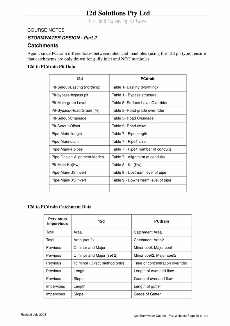
12d to PCdrain Pit Data
12d to PCdrain Catchment Data
12d PCdrain
Pit-Setout-Easting (northing) Table 1- Easting (Northing)
Pit-bypass-bypass pit Table 1 - Bypass structure
Pit-Main-grate Level Table 5- Surface Level Overrider
Pit-Bypass-Road Grade (%) Table 5- Road grade over rider
Pit-Setout-Chainage Table 5- Road Chainage
Pit-Setout-Offset Table 5- Road offset
Pipe-Main -length Table 7 - Pipe length
Pipe-Main-diam Table 7 - Pipe1 size
Pipe-Main-# pipes Table 7 - Pipe1 number of conduits
Pipe-Design-Alignment Modes Table 7 - Alignment of conduits
Pit-Main-Ku(Kw) Table 8 - Ku (Kw)
Pipe-Main-US invert Table 9 - Upstream level of pipe
Pipe-Main-DS invert Table 9 - Downstream level of pipe
Perviouus
Impervious12d PCdrain
Total Area Catchment Area
Total Area (set 2) Catchment Area2
Pervious C minor and Major Minor coef; Major coef
Pervious C minor and Major (set 2) Minor coef2; Major coef2
Pervious Tc minor (Direct method only) Time of concentration overrider
Pervious Length Length of overland flow
Pervious Slope Grade of overland flow
Impervious Length Length of gutter
Impervious Slope Grade of Gutter

Revised July 200812d Stormwater Course - Part 2 Notes: Page 56 of 110
12d Solutions Pty Ltd
COURSE NOTES
STORMWATER DESIGN - Part 2
13.2 12d to PCdrain
1. Export the data to PCdrain selected via the Network editor
Design=>Drainage-Sewer=>Drainage Network Editor
After selecting the drainage network, select the Import/Export button and the following dialogue
will appear.
Select the Run button and the interface file will be created.
2. Launch the PCdrain for Windows program. If you have a project set up with the design parame-
ters, rainfall data, inlet charts and gutter profiles then open it now and skip to step 8. Otherwise
continue with step 5.
3. The Design Parameters can be set as desired with the menu selection
Data=>Design Parameters.
4. Select the rainfall data using the Data=>Rainfall menu selection.
5. Select the inlet charts using the Data=>Inlet Charts menu selection. The pit types specified in
12d must be included in these settings. More - PCdrain to 12d pit converter
6. At least one gutter profile in PCdrain needs to be defined. These are set through the menu selec-
tion Data=>Gutter Profiles. The default gutter section name (Road ID) from 12d is 4d and
therefore it is recommended you create a profile with this name and your own description. If you
have changed the profile names in 12d (through the spreadsheet interface or the Attribute editor)
these new profile names will have to exist in PCdrain.
7. Save this file now so that you can retrieve it later if required. It can be used as a starting template
for new jobs.
8. File=>Import from the menu. Select the file exported in step 1. The information from 12d may
be viewed by selecting Data=>Network and then selecting the desired tabs.
9. The HGL level and the pipe elevation at the outlet should be set using the menu selection
Data=>Outlet.
10.If you have not exported pipe data then the pipe size must be determined. Use the menu selection
Process=>Select Pipe Sizes.
The drainage model will be completed
by the editor.
Select PCdrain Int (Windows) from
the drop down list.
Enter the name of the int file to be cre-
ated.
Select Export.
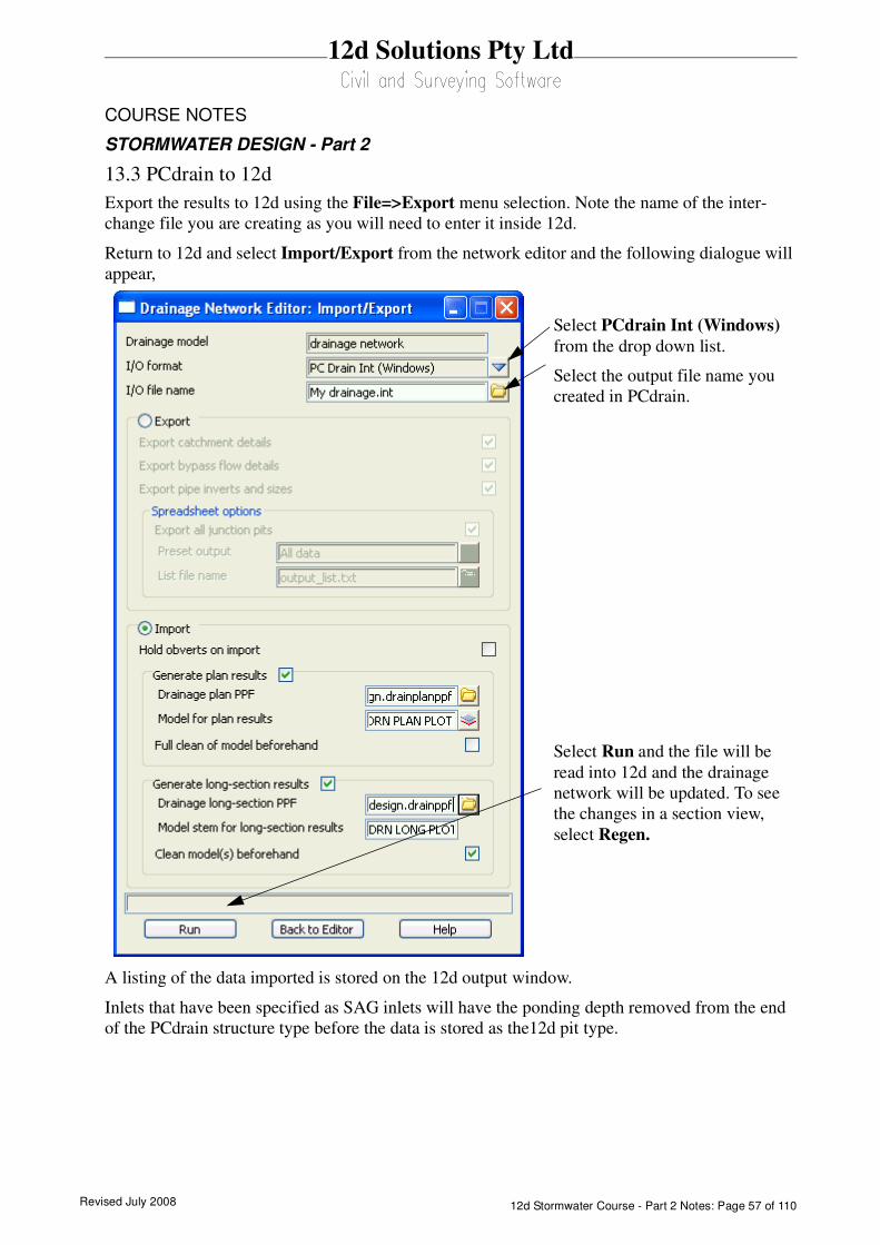
Revised July 2008 12d Stormwater Course - Part 2 Notes: Page 57 of 110
12d Solutions Pty Ltd
COURSE NOTES
STORMWATER DESIGN - Part 2
13.3 PCdrain to 12d
Export the results to 12d using the File=>Export menu selection. Note the name of the inter-
change file you are creating as you will need to enter it inside 12d.
Return to 12d and select Import/Export from the network editor and the following dialogue will
appear,
A listing of the data imported is stored on the 12d output window.
Inlets that have been specified as SAG inlets will have the ponding depth removed from the end
of the PCdrain structure type before the data is stored as the12d pit type.
Select PCdrain Int (Windows)
from the drop down list.
Select the output file name you
created in PCdrain.
Select Run and the file will be
read into 12d and the drainage
network will be updated. To see
the changes in a section view,
select Regen.
Revised July 200812d Stormwater Course - Part 2 Notes: Page 58 of 110
12d Solutions Pty Ltd
COURSE NOTES
STORMWATER DESIGN - Part 2
14.0 Running Drains - Version 2 onwards
Key Points
1. The Drains database (each project has its own) and the12d database (drainage.4d) must be syn-
chronised (More).
2. 12d Version 8 needs you to create a new drainage.4d file to include the new inlet capacity curves
(pit groups are no longer used).
3. For pits with a bypass pit and road grade defined (non ILLUDAS), 12d selects pit families for
Drains in the following way
The users selects the pit type (Drains pit size) in 12d and 12d selects the ongrade or sag curve
from the drainage.4d file (see inlet capacity calculations). The names of these curves are the
Drains pit families. If there are no curves for the pit type in the drainage.4d file then the Drains pit
type is exported as ILLUDAS with no family or size data.
If the 12d pit type is Headwall then the pit will be exported as a headwall.
4. Catchment lengths, slopes and roughness values are NOT exported in the Drains Rational format.
The default values for these parameters are NOT exported in the Drains ILSAX format but the
explicit settings from the catchment panel are exported. If used, Drains requires length, slope and
roughness for both impervious (paved) and pervious (grass). Supplementary values must entered
in Drains.
5. Data is copied from 12d to the Windows clipboard and then pasted into Drains. 12d can not delete
any objects in Drains, it can only add and update.
6. When updating 12d from Drains, always copy the DATA to 12d before the results. 12d will
update the network but will not add or delete pits.
7. If a new pit is added in Drains, the user willhave the option to create it in 12d. If it is created only
the pit will be added and not the pipes.
Why Do I get ILLUDAS pits?
1. The bypass pit is blank. There must bypass pit for the water to go to. Bypass flow strings must
pass within 1 pit diameter (beware pits with zero manhole diameters) and you can enter them
manually.
2. The pit type selected has no capacity curves in the drainage.4d file. The curve names become the
pit family for the export to Drains. No pit family means ILLUDAS.
If you are intentionally using a drainage.4d file with NO inlet capacity curves, the pit families you
set in Drains will be remembered by 12d when you import back into 12d. The inlet capacity
curves will not be required for your next export to Drains.
14.1 Drains Interface Overview
The Drains program performs the rational or ILSAX hydrology calculations as well as hydraulic
Revised July 2008 12d Stormwater Course - Part 2 Notes: Page 59 of 110
12d Solutions Pty Ltd
COURSE NOTES
STORMWATER DESIGN - Part 2
grade line calculations that determine pipe sizes and pipe invert levels.
The data sent to Drains includes
s pit names and types, easting and northing data with surface levels
s finished surface profile along the centre line of the pipes
s Headwalls and their levels
s optional - bypass inlets, road grades/crossfalls and SAG Inlet Calculations (ponding
volumes and depths). Pit family selection using road grade and crossfall data.
s optional - composite catchment area create from three12d areas per inlet (must alter
the mapping file)
s catchment characteristics, k values and overland travel times
s pipe sizes, type and invert levels
Data is copied from 12d to the Windows clipboard and then pasted into Drains (Edit=>Paste
data from spreadsheet). 12d can not delete any objects in Drains, it can only add and update.
The Drains menu selection Run=>Design is used to design the network. Once the drainage net-
work has been designed in Drains the updated design data (Edit=>Copy data to spreadsheet)
and/or the hydraulic results (Edit=>Copy results to spreadsheet) are sent back to 12d via the
clipboard.
Always copy the DATA to 12d before the results as the results are deleted inside 12d with
every update of the data!
14.2 Catchment Data
Drains has one catchment per inlet and therefore only 12d’s catchment set one is used in the inter-
face. The 12d catchment is split a pervious (grass) area and an impervious (paved) area using the
percent impervious fraction. The rational and ilsax spreadsheet export formats (selected in the
import/export panel) are different.
The Rational format of the Drains interface does not export Drains “more detailed data”. The
ilsax format does support the “more detailed data” format but the user must define the length,
slope and roughness in the catchment panel. No 12d DNE default data will be exported. As 12d
does not have a supplementary area this data will have to be entered into Drains. Gutter lengths
and slopes are calculated from the upstream section of the longest overland flow path entering the
inlet.
Supplementary data entered in Drains will be remembered in 12d for the next export. The grassed
percentage for the next export is calculated as the (100 - % impervious - % supplementary).
14.3 Synchronising the Drains database and the drainage.4d file.
The 12d pipe types are always used to interface with Drains. Ongrade or SAG pits will be cre-
ated for export to Drains if the 12d pit has a bypass pit, road grade and a pit type with inlet capac-
ity curves. If all three are not present it will be exported as an ILLUDAS pit.

Revised July 200812d Stormwater Course - Part 2 Notes: Page 60 of 110
12d Solutions Pty Ltd
COURSE NOTES
STORMWATER DESIGN - Part 2
Every Drains file begins with a default database and Drains uses that database for the life of the
project. This database must by synchronised with the drainage.4d file in 12d to ensure the Drains pit
families, pit sizes, pipe types and overflow route types match. Therefore it is highly recommended
that copy of the drainage.4d file be kept in the 12d working folder.
The Drains and 12d data must match as follows.
Note: If Drains is to be used to select the pit size then an exact match in pit types is not required. For
this case the 12d pit type need only be the prefix of the Drains pit size.
The following 6 steps will help ensure 12d is synchronised with Drains. More details are given in the
sections below.
1)Prepare the Drains Pit Database
IF 12d is to select the Drains Pit Size, then the Drains Pit Size and 12d Pit types have to match,
exactly! If Drains is used to determine the pit size then you may skip this step.
The pit databases supplied by Drains often have road grade and/or crossfall attached to the end of the
pit size. THIS EXTRA DATA MUST BE REMOVED!
For example, in Drains database you may find the following
Pit family Pit size
NSW RTA SA Inlet, 3% crossfall, 1% grade SA1 (Type 2) - 1% longitudinal grade
and
NSW RTA SA Inlet, 3% crossfall, 3% grade SA1 (Type 2) - 3% longitudinal grade
The pit size for both is the same, SA1, but 12d can not tell this because of all the extra data at the
end. In Drains, simply remove the extra information so that they are both SA1. If the network already
exists in Drains, then Drains will automatically change the names of the sizes you have already
selected. No time lost here.
Once you have changed the Drains pit size names, you are ready to use the Drains to drainage.4d
routine to create a drainage.4d file that is synchronised with Drains.
2)Export the Drains database from your Drains file
Inside Drains Open your drains file or begin with a blank file. Select Project=>Overflow Route
Drains database drainage.4d
Pipe type Pipe type entries
Drains database drainage.4d
Pit size Pit type
Pit famly ongrade or sag curve names
Overland route database default in mapping file
Only if bypass flow is required
Revised July 2008 12d Stormwater Course - Part 2 Notes: Page 61 of 110
12d Solutions Pty Ltd
COURSE NOTES
STORMWATER DESIGN - Part 2
database. Then select OK and then YES. This will cause Drains to export the database to the file
“Drains Connection Data.txt” and store it in the folder with the Drains program.
3)Create a drainage.4d file from the Drains file
s From the 12d menu select Design->Drainage-Sewer->More->Drains to drain-
age.4d.
s Select Copy Drains database to copy the file to the 12d working folder.
s select Create drainage.4d. The Drains database dump file is copied to the 12d work-
ing folder and a drainage.4d file is created in the 12d working folder.
s More details below.
4)Edit the drainage.4d file
From the 12d menu select Design->Drainage-Sewer->More->Edit drainage.4d. Select Find
then edit from the file more info button. Set the road grade and crossfalls for the 12d pit
groups.More details below.
5)Restart 12d
From the 12d menu select Project->Restart.
6)Set the Overflow shape, Update Pit and Pipe types (Optional)
If the network has already been created using pit and pipe types that no longer exist in the drain-
age.4d file, they will have to be updated before the export to Drains can occur. You may update
them using the drainage network editor (one at a time) or you may set all of the pit and pipes types
to one value using this routine.Later you may change them individually using the Drainage net-
work editor
This routine will also set a default overflow route shape for export (values can be modified in the
Drains program if desired).
From the 12d menu select Design->Drainage-Sewer->More->Drainage io defaults.
More details below.
14.4 Drains to drainage.4d file
Position of option on menu: Design =>Drainage-Sewer =>More=>Drains to drainage.4d
On selecting the Drains to drainage.4doption, the Drains to drainage.4d panel is displayed.
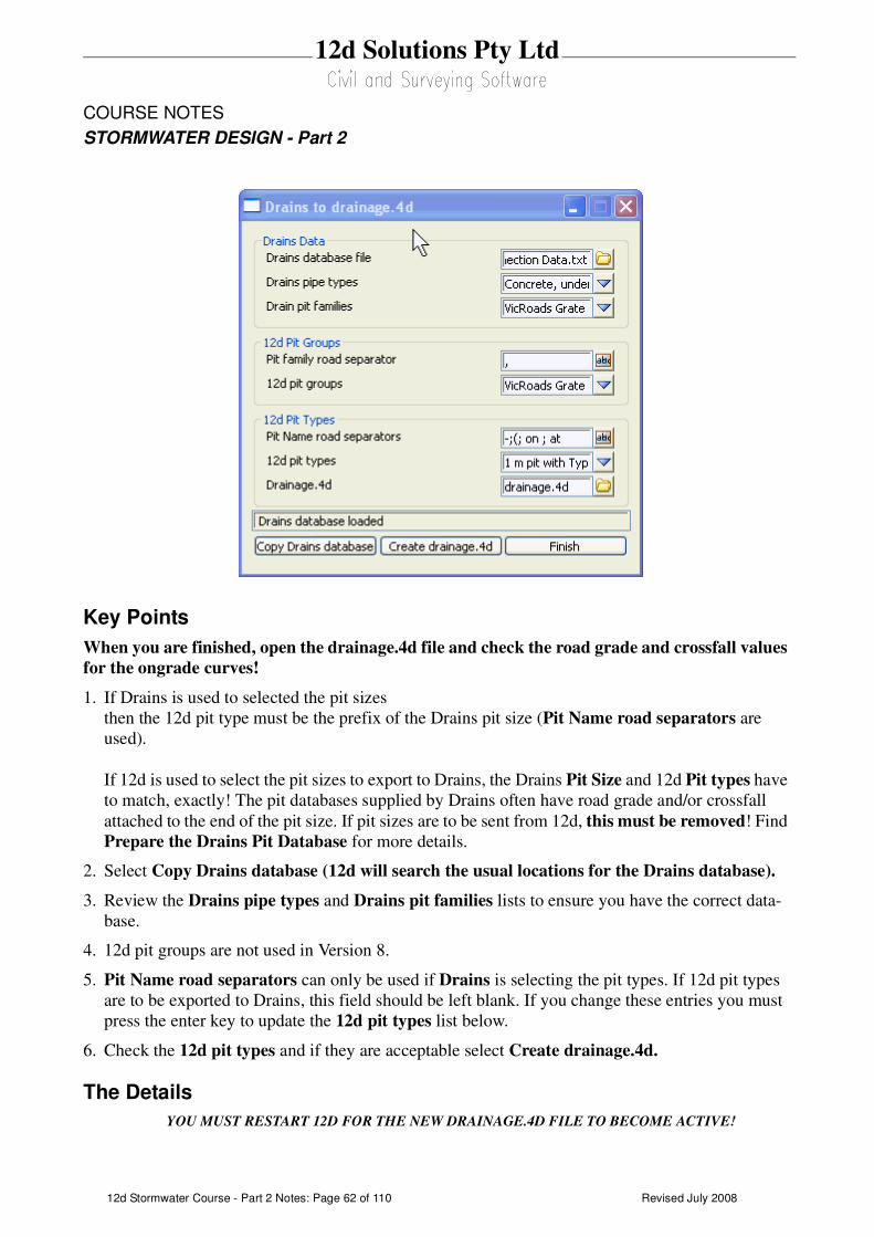
Revised July 200812d Stormwater Course - Part 2 Notes: Page 62 of 110
12d Solutions Pty Ltd
COURSE NOTES
STORMWATER DESIGN - Part 2
Key Points
When you are finished, open the drainage.4d file and check the road grade and crossfall values
for the ongrade curves!
1. If Drains is used to selected the pit sizes
then the 12d pit type must be the prefix of the Drains pit size (Pit Name road separators are
used).
If 12d is used to select the pit sizes to export to Drains, the Drains Pit Size and 12d Pit types have
to match, exactly! The pit databases supplied by Drains often have road grade and/or crossfall
attached to the end of the pit size. If pit sizes are to be sent from 12d, this must be removed! Find
Prepare the Drains Pit Database for more details.
2. Select Copy Drains database (12d will search the usual locations for the Drains database).
3. Review the Drains pipe types and Drains pit families lists to ensure you have the correct data-
base.
4. 12d pit groups are not used in Version 8.
5. Pit Name road separators can only be used if Drains is selecting the pit types. If 12d pit types
are to be exported to Drains, this field should be left blank. If you change these entries you must
press the enter key to update the 12d pit types list below.
6. Check the 12d pit types and if they are acceptable select Create drainage.4d.
The Details
YOU MUST RESTART 12D FOR THE NEW DRAINAGE.4D FILE TO BECOME ACTIVE!
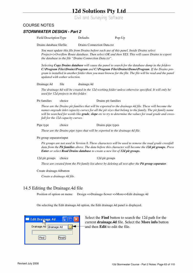
Revised July 2008 12d Stormwater Course - Part 2 Notes: Page 63 of 110
12d Solutions Pty Ltd
COURSE NOTES
STORMWATER DESIGN - Part 2
Field Description Type Defaults Pop-Up
Drains database filefile Drains Connection Data.txt
You must update this file from Drains before each use of this panel. Inside Drains select
Project=>Overflow Route database. Then select OK and then YES. This will cause Drains to export
the database to the file “Drains Connection Data.txt”.
Selecting Copy Drains database will cause the panel to search for the database dump in the folders
C:\Program Files\Drains\Program and C:\Program Files\Drains\Demo\Program. If the Drains pro-
gram is installed in another folder then you must browse for the file. The file will be read and the panel
updated with eother selection.
Drainage.4d file drainage.4d
The drainage.4d will be created in the 12d working folder unless otherwise specified. It will only be
used for 12d projects in this folder.
Pit families choice Drains pit families
These are the Drains pit families that will be exported to the drainage.4d file. These will become the
names ongrade inlet capacity curves for all the pit sizes that belong to the family. The pit family name
will be searched for words like grade, slope etc to try to determine the values for road grade and cross-
fall for the 12d capacity curves.
Pipe type choice Drains pipe types
These are the Drains pipe types that will be exported to the drainage.4d file.
Pit group separatorinput
Pit groups are not used in Version 8. These characters will be used to remove the road grade crossfall
data from the Pit families above. The data before this character will become the 12d pit groups. Press
Enter or select Read Drains database to create a new list of 12d pit groups.
12d pit groups choice 12d pit groups
These are created from the Pit family list above by deleting all text after the Pit group separator.
Create drainage.4dbutton
Create a drainage.4d file.
14.5 Editing the Drainage.4d file
Position of option on menu: Design =>Drainage-Sewer =>More=>Edit drainage.4d
On selecting the Edit drainage.4d option, the Edit drainage.4d panel is displayed.
Select the Find button to search the 12d path for the
current drainage.4d file. Select the More info button
and then Edit to edit the file.

Revised July 200812d Stormwater Course - Part 2 Notes: Page 64 of 110
12d Solutions Pty Ltd
COURSE NOTES
STORMWATER DESIGN - Part 2
The drainage.4d file contains Manhole and Pipe commands. 12d also uses the Manhole commands to
specify a pit group by using the prefix “group”. Details follow.
Headwalls
The pit type “Headwall” (case sensitive for Drains) is reserved for the inlet headwall for a conduit.
Drains does not use this for an outlet headwall.
If the inlet type is On Grade or there is no bypass pit, the grate level is exported as the Drains surface
level. If the Inlet type is marked as a SAG pit then the surface level will be calculated from the low
point on the catchment string (catchment set #1). Also see SAG Inlet Calculations.
Pit Families
Version 2+ of the Drains clipboard interface uses a pit family to describe the kerb shape and option-
ally, the name include the road crossfall and/or grade attached as a suffix.
An example pit group is the drainage.4d file is shown below.12d uses the road grade and/or the road
crossfall to select which pit family should be sent to Drains. In this example the road crossfall would
not be used in selecting the pit family.
It is up to the user to decide the grade when the next pit family should be used. In this case the
threshold value for the gutter grade is set midway between the published values of the inlet curves.
For example at a gutter grade of 2% 12d starts sending the NSW RTA Pits - 3% slope pit family.
The pit families listed on the right must match exactly with those in the Drains pit database.
Pit Types and Pit Sizes
Each Drains pit family has several pit sizes. The Drains pit sizes link to the12d pit types and there-
fore all Drains pit sizes should exist in the 12d drainage.4d file.
The pit size will be read back from Drains into 12d as the pit type so that it can be placed on the
drainage long sections and pit schedules. If no matching pit type is found in 12d then a character will
be dropped off the end of the Drains pit size and 12d will be searched for the new shorter pit type.
This will be repeated till a match is found (or there are no more characters in the Drains pit size).
Pipe Types
The pipe type selected in 12d must exist in the pipe database inside Drains. Simple “2” for class 2 or
“RCP “do not exist in Drains.
14.6 Setting the Overflow Route, the Pit and Pipe types
Position of option on menu: Design =>Drainage-Sewer =>More=>Drainage IO Defaults
On selecting the Drainage IO Defaults option, the Drainage IO Defaults panel is displayed.
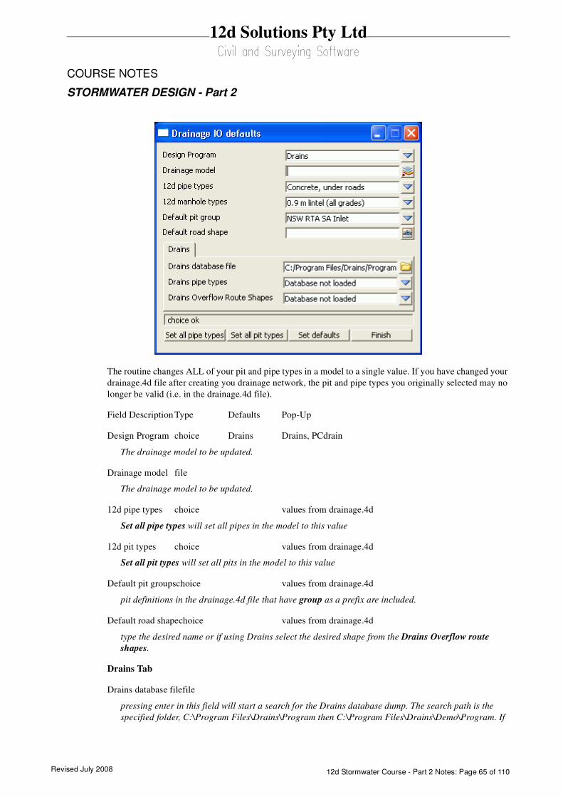
Revised July 2008 12d Stormwater Course - Part 2 Notes: Page 65 of 110
12d Solutions Pty Ltd
COURSE NOTES
STORMWATER DESIGN - Part 2
The routine changes ALL of your pit and pipe types in a model to a single value. If you have changed your
drainage.4d file after creating you drainage network, the pit and pipe types you originally selected may no
longer be valid (i.e. in the drainage.4d file).
Field Description Type Defaults Pop-Up
Design Program choice Drains Drains, PCdrain
The drainage model to be updated.
Drainage model file
The drainage model to be updated.
12d pipe types choice values from drainage.4d
Set all pipe types will set all pipes in the model to this value
12d pit types choice values from drainage.4d
Set all pit types will set all pits in the model to this value
Default pit groupschoice values from drainage.4d
pit definitions in the drainage.4d file that have group as a prefix are included.
Default road shapechoice values from drainage.4d
type the desired name or if using Drains select the desired shape from the Drains Overflow route
shapes.
Drains Tab
Drains database filefile
pressing enter in this field will start a search for the Drains database dump. The search path is the
specified folder, C:\Program Files\Drains\Program then C:\Program Files\Drains\Demo\Program. If
Revised July 200812d Stormwater Course - Part 2 Notes: Page 66 of 110
12d Solutions Pty Ltd
COURSE NOTES
STORMWATER DESIGN - Part 2
the file is found the choice fields below are populated. It is highly recommended that this file be in the
12d working folder.
Drains pipe typeschoice l values from Drains file
the pipe types are retrieved from the last Drains database dump. Changing this value will update the 12
pipe types above.
Drains Overflow Route Shapeschoice values from Drains file
the overflow route shapes are retrieved from the last Drains database dump. Changing this value will
update the Default road shape above.
Set all pipe types button
all pipe types in model are set to this value
Set all pit types button
all pit types in model are set to this value
Set defaults button
the defaults for the Drains Overflow Route Shapes and 12d pit group are set
Finish button
removes the panel
14.7 Drains Version 2+ Requirements
Pit Names
The 12d pit names cannot be more than 9 characters long. 12d uses 2 additional characters to the pit
name at export time create names for the pipes, overflow routes and catchments. For example pit “A-
1” will have a bypass route “F A-1”, a catchment “C A-1” and a downstream pipe “P A-1”.
Bypass Flow (Overland Flow Routes)
There are 3 requirements for Drains bypass flow (bypass pit, pit inlet capacity curve and road grade/
crossfall).
1. Select a pit type that has ongrade or sag inlet capacity curves defined in the drainage.4d file. The
Drains and 12d databases must be in sync.
2. Bypass strings in the Bypass route model specified (Network editor->Global->Utility Models-
>Bypass flow model. For more details see Bypass Flow.
3. Road grade and crossfall calculated (Network editor->Global->Utility Models->Road design file)
The overland flow strings are not allowed to pass through the outlet pit on the network.
SAG Inlet Calculations
SAG inlets are inlets where the water ponds at the surface rather than flowing past. If a SAG inlet
has a catchment string the overflow depth and volume are calculated. The catchment string from Set
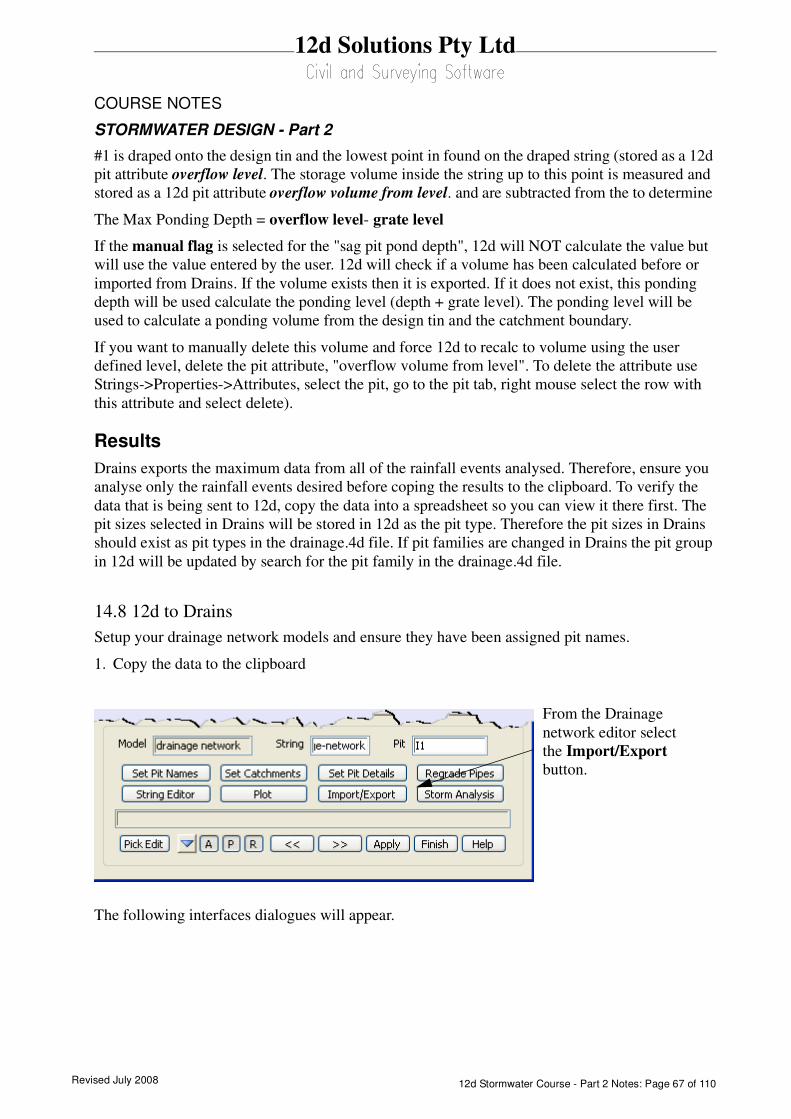
Revised July 2008 12d Stormwater Course - Part 2 Notes: Page 67 of 110
12d Solutions Pty Ltd
COURSE NOTES
STORMWATER DESIGN - Part 2
#1 is draped onto the design tin and the lowest point in found on the draped string (stored as a 12d
pit attribute overflow level. The storage volume inside the string up to this point is measured and
stored as a 12d pit attribute overflow volume from level. and are subtracted from the to determine
The Max Ponding Depth = overflow level- grate level
If the manual flag is selected for the "sag pit pond depth", 12d will NOT calculate the value but
will use the value entered by the user. 12d will check if a volume has been calculated before or
imported from Drains. If the volume exists then it is exported. If it does not exist, this ponding
depth will be used calculate the ponding level (depth + grate level). The ponding level will be
used to calculate a ponding volume from the design tin and the catchment boundary.
If you want to manually delete this volume and force 12d to recalc to volume using the user
defined level, delete the pit attribute, "overflow volume from level". To delete the attribute use
Strings->Properties->Attributes, select the pit, go to the pit tab, right mouse select the row with
this attribute and select delete).
Results
Drains exports the maximum data from all of the rainfall events analysed. Therefore, ensure you
analyse only the rainfall events desired before coping the results to the clipboard. To verify the
data that is being sent to 12d, copy the data into a spreadsheet so you can view it there first. The
pit sizes selected in Drains will be stored in 12d as the pit type. Therefore the pit sizes in Drains
should exist as pit types in the drainage.4d file. If pit families are changed in Drains the pit group
in 12d will be updated by search for the pit family in the drainage.4d file.
14.8 12d to Drains
Setup your drainage network models and ensure they have been assigned pit names.
1. Copy the data to the clipboard
The following interfaces dialogues will appear.
From the Drainage
network editor select
the Import/Export
button.
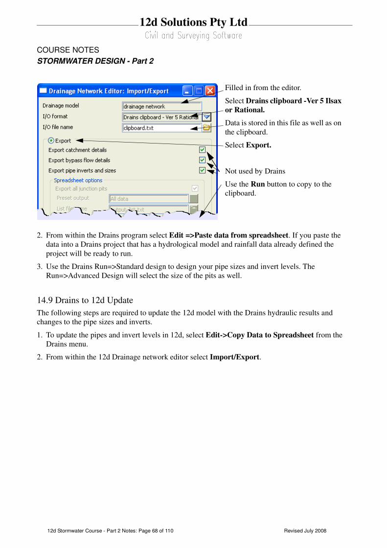
Revised July 200812d Stormwater Course - Part 2 Notes: Page 68 of 110
12d Solutions Pty Ltd
COURSE NOTES
STORMWATER DESIGN - Part 2
2. From within the Drains program select Edit =>Paste data from spreadsheet. If you paste the
data into a Drains project that has a hydrological model and rainfall data already defined the
project will be ready to run.
3. Use the Drains Run=>Standard design to design your pipe sizes and invert levels. The
Run=>Advanced Design will select the size of the pits as well.
14.9 Drains to 12d Update
The following steps are required to update the 12d model with the Drains hydraulic results and
changes to the pipe sizes and inverts.
1. To update the pipes and invert levels in 12d, select Edit->Copy Data to Spreadsheet from the
Drains menu.
2. From within the 12d Drainage network editor select Import/Export.
Filled in from the editor.
Select Drains clipboard -Ver 5 Ilsax
or Rational.
Data is stored in this file as well as on
the clipboard.
Select Export.
Not used by Drains
Use the Run button to copy to the
clipboard.
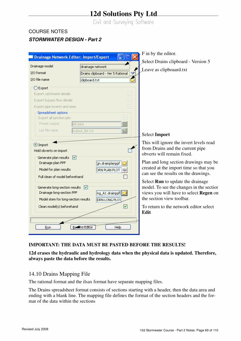
Revised July 2008 12d Stormwater Course - Part 2 Notes: Page 69 of 110
12d Solutions Pty Ltd
COURSE NOTES
STORMWATER DESIGN - Part 2
IMPORTANT: THE DATA MUST BE PASTED BEFORE THE RESULTS!
12d erases the hydraulic and hydrology data when the physical data is updated. Therefore,
always paste the data before the results.
14.10 Drains Mapping File
The rational format and the ilsax format have separate mapping files.
The Drains spreadsheet format consists of sections starting with a header, then the data area and
ending with a blank line. The mapping file defines the format of the section headers and the for-
mat of the data within the sections
F in by the editor.
Select Drains clipboard - Version 5
Leave as clipboaard.txt
Select Import
This will ignore the invert levels read
from Drains and the current pipe
obverts will remain fixed.
Plan and long section drawings may be
created at the import time so that you
can see the results on the drawings.
Select Run to update the drainage
model. To see the changes in the section
views you will have to select Regen on
the section view toolbar.
To return to the network editor select
Edit
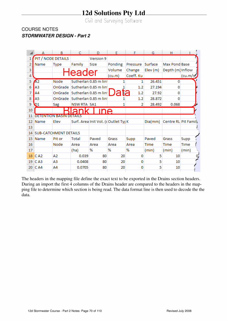
Revised July 200812d Stormwater Course - Part 2 Notes: Page 70 of 110
12d Solutions Pty Ltd
COURSE NOTES
STORMWATER DESIGN - Part 2
The headers in the mapping file define the exact text to be exported in the Drains section headers.
During an import the first 4 columns of the Drains header are compared to the headers in the map-
ping file to determine which section is being read. The data format line is then used to decode the the
data.

Revised July 2008 12d Stormwater Course - Part 2 Notes: Page 71 of 110
12d Solutions Pty Ltd
COURSE NOTES
STORMWATER DESIGN - Part 2
15.0 Running XPSWMM and RAT2000
The drainage design with all three of the XP software programs follows the same methodology.
The process is substantially automated with the XP-SWMM program so that the XPX file is auto-
matically read by XP-SWMM and automatically created when leaving XP-SWMM.
Drainage design with XP programs includes the following steps.
1. 12d creates an XPX file that is read by the XP programs.
2. The XP program is then run in the design mode to determine the pipe sizes and invert levels.
3. If bypass and overland flows are to be modelled then the inlet capacities need to be defined and
then run the XP program in the Full Analysis Model.
4. The XP program creates an XPX file for 12d to import.
15.1 xpstorm and xpswmm bypass requirements
12d will select the inlet capacity curves for the xp programs when the following bypass settings
are complete
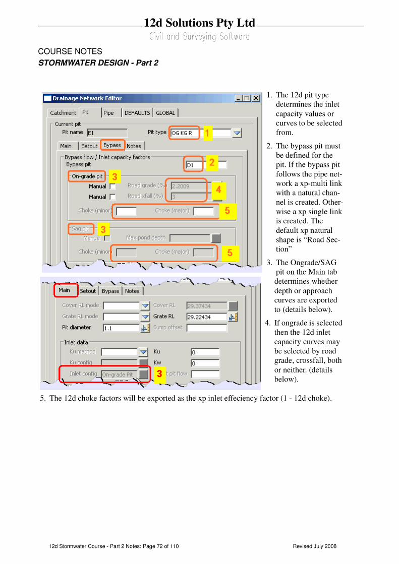
Revised July 200812d Stormwater Course - Part 2 Notes: Page 72 of 110
12d Solutions Pty Ltd
COURSE NOTES
STORMWATER DESIGN - Part 2
1. The 12d pit type
determines the inlet
capacity values or
curves to be selected
from.
2. The bypass pit must
be defined for the
pit. If the bypass pit
follows the pipe net-
work a xp-multi link
with a natural chan-
nel is created. Other-
wise a xp single link
is created. The
default xp natural
shape is “Road Sec-
tion”
3. The Ongrade/SAG
pit on the Main tab
determines whether
depth or approach
curves are exported
to (details below).
4. If ongrade is selected
then the 12d inlet
capacity curves may
be selected by road
grade, crossfall, both
or neither. (details
below).
5. The 12d choke factors will be exported as the xp inlet effeciency factor (1 - 12d choke).
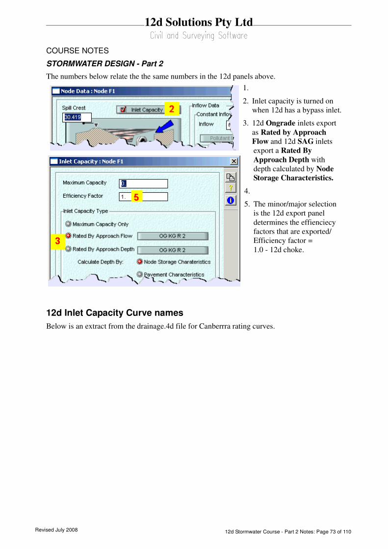
Revised July 2008 12d Stormwater Course - Part 2 Notes: Page 73 of 110
12d Solutions Pty Ltd
COURSE NOTES
STORMWATER DESIGN - Part 2
The numbers below relate the the same numbers in the 12d panels above.
12d Inlet Capacity Curve names
Below is an extract from the drainage.4d file for Canberrra rating curves.
1.
2. Inlet capacity is turned on
when 12d has a bypass inlet.
3. 12d Ongrade inlets export
as Rated by Approach
Flow and 12d SAG inlets
export a Rated By
Approach Depth with
depth calculated by Node
Storage Characteristics.
4.
5. The minor/major selection
is the 12d export panel
determines the effienciecy
factors that are exported/
Efficiency factor =
1.0 - 12d choke.

Revised July 200812d Stormwater Course - Part 2 Notes: Page 74 of 110
12d Solutions Pty Ltd
COURSE NOTES
STORMWATER DESIGN - Part 2
1. The manhole is the inlet type selected above.
2. cap_config G forces the inlet to be used as qa 12d ongrade inlet. An S would be SAG and an M a
manhole.
3. The curve name indicated here is exported as the xp inlet capacity curve.
4. The curve name will be exported starting at road grade of 0. Since one curve has a road grade
value all curves must have a road grade value and the user must have a road grade calculated on
the 12d bypass tab.
15.2 12d to the XP Programs
The x,y pit layouts and the cover/surface levels are obtained from your drainage network while the
catchment and overland flow data comes from the models specified in the drainage interface dia-
logue.
The steps required to transfer the data to the XP programs are as follows.
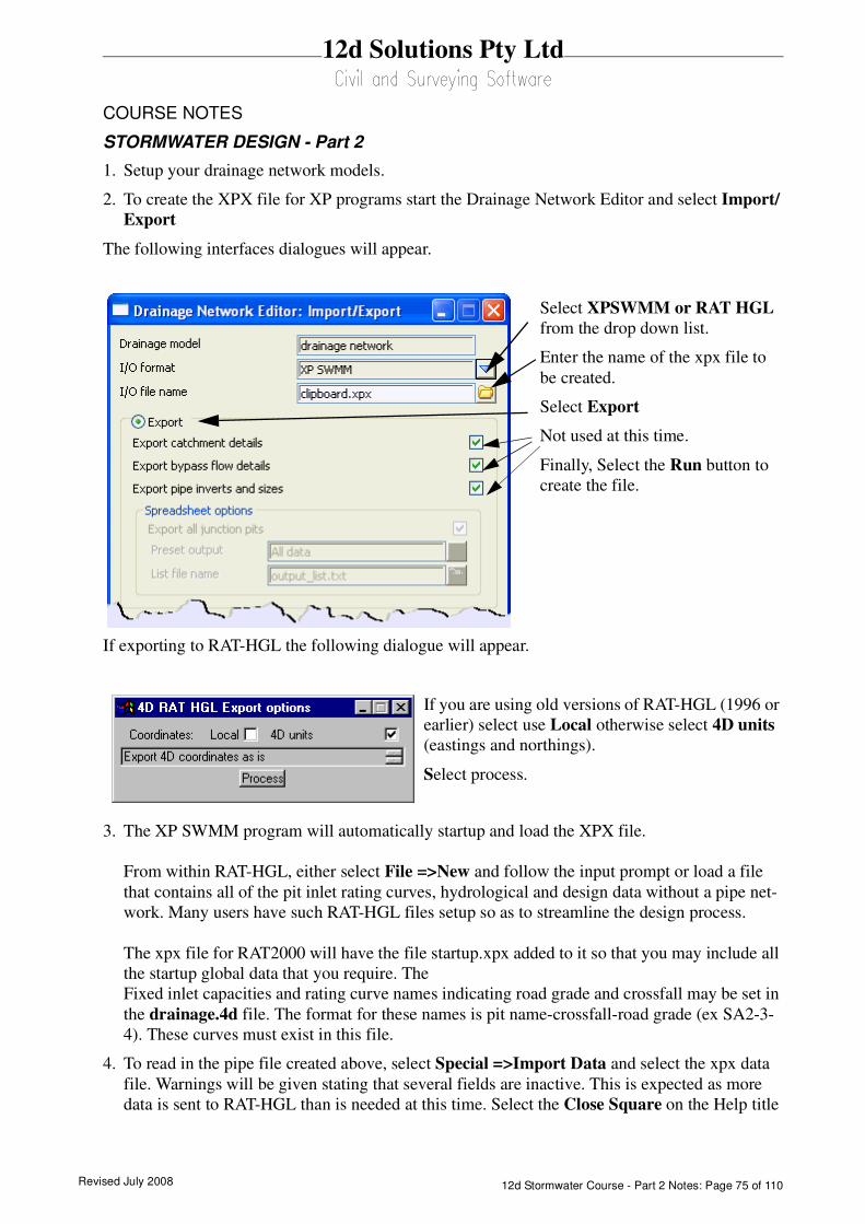
Revised July 2008 12d Stormwater Course - Part 2 Notes: Page 75 of 110
12d Solutions Pty Ltd
COURSE NOTES
STORMWATER DESIGN - Part 2
1. Setup your drainage network models.
2. To create the XPX file for XP programs start the Drainage Network Editor and select Import/
Export
The following interfaces dialogues will appear.
If exporting to RAT-HGL the following dialogue will appear.
3. The XP SWMM program will automatically startup and load the XPX file.
From within RAT-HGL, either select File =>New and follow the input prompt or load a file
that contains all of the pit inlet rating curves, hydrological and design data without a pipe net-
work. Many users have such RAT-HGL files setup so as to streamline the design process.
The xpx file for RAT2000 will have the file startup.xpx added to it so that you may include all
the startup global data that you require. The
Fixed inlet capacities and rating curve names indicating road grade and crossfall may be set in
the drainage.4d file. The format for these names is pit name-crossfall-road grade (ex SA2-3-
4). These curves must exist in this file.
4. To read in the pipe file created above, select Special =>Import Data and select the xpx data
file. Warnings will be given stating that several fields are inactive. This is expected as more
data is sent to RAT-HGL than is needed at this time. Select the Close Square on the Help title
Select XPSWMM or RAT HGL
from the drop down list.
Enter the name of the xpx file to
be created.
Select Export
Not used at this time.
Finally, Select the Run button to
create the file.
If you are using old versions of RAT-HGL (1996 or
earlier) select use Local otherwise select 4D units
(eastings and northings).
Select process.
Revised July 200812d Stormwater Course - Part 2 Notes: Page 76 of 110
12d Solutions Pty Ltd
COURSE NOTES
STORMWATER DESIGN - Part 2
area and the pipe network and catchments should now appear on the screen.
5. If you want RAT-HGL to redesign you network, change the analysis mode to Design mode by
selecting Special=>Job Control and Select Design mode. Do not do this if you want to analyse
the network you layed out in 12d (used for existing systems).
6. Select the rainfall events to design/analyse and the LB (twice) on OK to return to the layout. Now
select the outlet and enter the starting tailwater levels.
7. Now you can run RAT-HGL (Special =>Solve).
15.3 XP Programs to 12d
Once you have your design finished, the following steps are required to update your 12d model. Your
design may contain several return periods in the analysis (Rp1 to Rp7) but 12d reads only the results
from Rp1. The following table is taken from the RATHGL output file (*.out extension) and the
results indicated are read back into 12d via the xpx file.
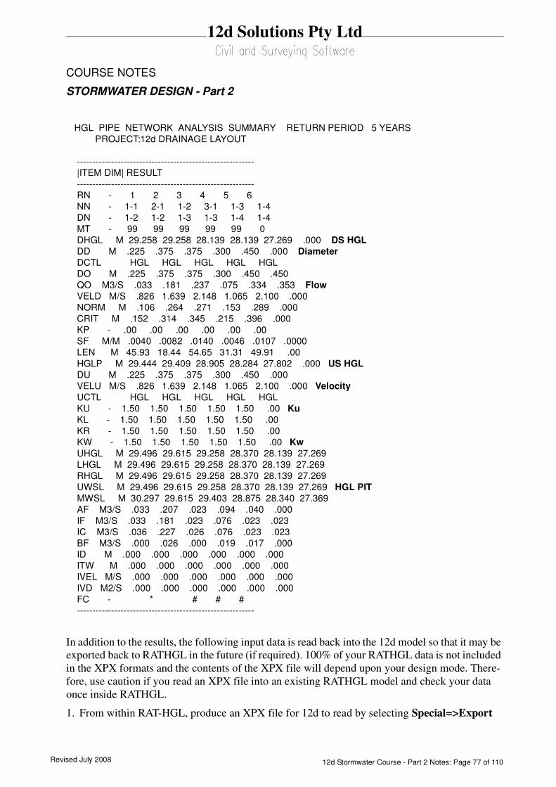
Revised July 2008 12d Stormwater Course - Part 2 Notes: Page 77 of 110
12d Solutions Pty Ltd
COURSE NOTES
STORMWATER DESIGN - Part 2
In addition to the results, the following input data is read back into the 12d model so that it may be
exported back to RATHGL in the future (if required). 100% of your RATHGL data is not included
in the XPX formats and the contents of the XPX file will depend upon your design mode. There-
fore, use caution if you read an XPX file into an existing RATHGL model and check your data
once inside RATHGL.
1. From within RAT-HGL, produce an XPX file for 12d to read by selecting Special=>Export
HGL PIPE NETWORK ANALYSIS SUMMARY RETURN PERIOD 5 YEARS
PROJECT:12d DRAINAGE LAYOUT
---------------------------------------------------------
|ITEM DIM| RESULT
---------------------------------------------------------
RN - 1 2 3 4 5 6
NN - 1-1 2-1 1-2 3-1 1-3 1-4
DN - 1-2 1-2 1-3 1-3 1-4 1-4
MT - 99 99 99 99 99 0
DHGL M 29.258 29.258 28.139 28.139 27.269 .000 DS HGL
DD M .225 .375 .375 .300 .450 .000 Diameter
DCTL HGL HGL HGL HGL HGL
DO M .225 .375 .375 .300 .450 .450
QO M3/S .033 .181 .237 .075 .334 .353 Flow
VELD M/S .826 1.639 2.148 1.065 2.100 .000
NORM M .106 .264 .271 .153 .289 .000
CRIT M .152 .314 .345 .215 .396 .000
KP - .00 .00 .00 .00 .00 .00
SF M/M .0040 .0082 .0140 .0046 .0107 .0000
LEN M 45.93 18.44 54.65 31.31 49.91 .00
HGLP M 29.444 29.409 28.905 28.284 27.802 .000 US HGL
DU M .225 .375 .375 .300 .450 .000
VELU M/S .826 1.639 2.148 1.065 2.100 .000 Velocity
UCTL HGL HGL HGL HGL HGL
KU - 1.50 1.50 1.50 1.50 1.50 .00 Ku
KL - 1.50 1.50 1.50 1.50 1.50 .00
KR - 1.50 1.50 1.50 1.50 1.50 .00
KW - 1.50 1.50 1.50 1.50 1.50 .00 Kw
UHGL M 29.496 29.615 29.258 28.370 28.139 27.269
LHGL M 29.496 29.615 29.258 28.370 28.139 27.269
RHGL M 29.496 29.615 29.258 28.370 28.139 27.269
UWSL M 29.496 29.615 29.258 28.370 28.139 27.269 HGL PIT
MWSL M 30.297 29.615 29.403 28.875 28.340 27.369
AF M3/S .033 .207 .023 .094 .040 .000
IF M3/S .033 .181 .023 .076 .023 .023
IC M3/S .036 .227 .026 .076 .023 .023
BF M3/S .000 .026 .000 .019 .017 .000
ID M .000 .000 .000 .000 .000 .000
ITW M .000 .000 .000 .000 .000 .000
IVEL M/S .000 .000 .000 .000 .000 .000
IVD M2/S .000 .000 .000 .000 .000 .000
FC - * # # #
---------------------------------------------------------
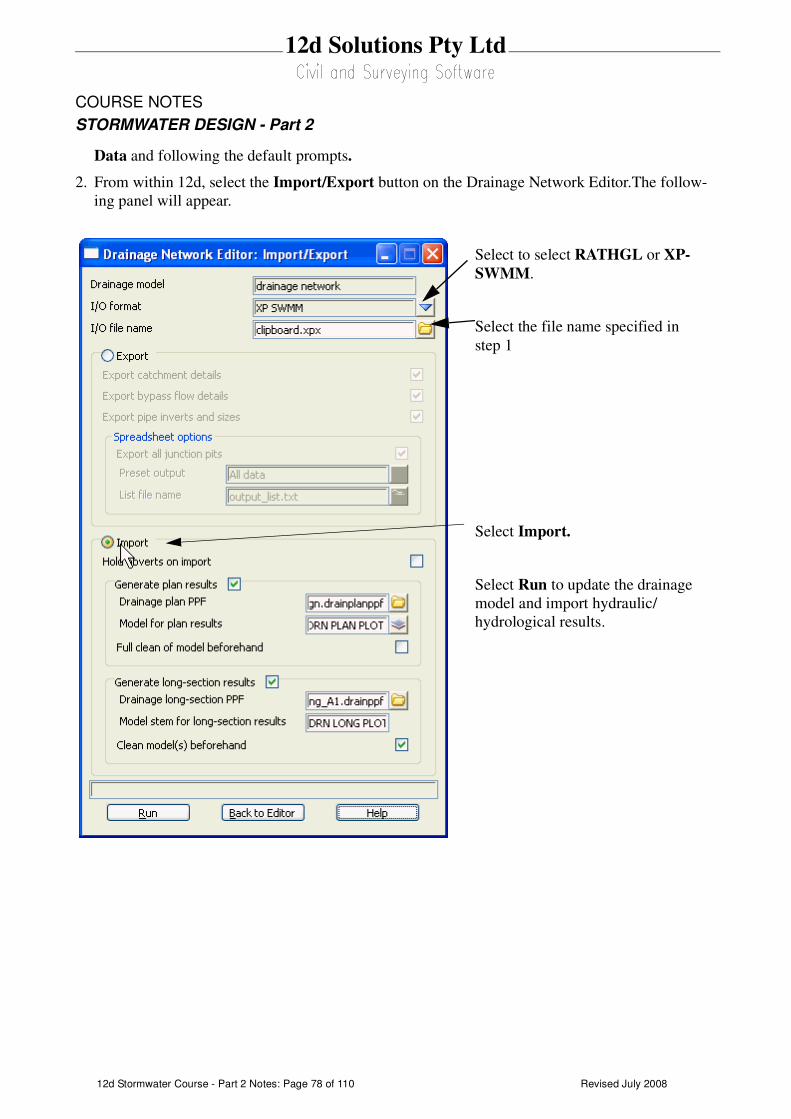
Revised July 200812d Stormwater Course - Part 2 Notes: Page 78 of 110
12d Solutions Pty Ltd
COURSE NOTES
STORMWATER DESIGN - Part 2
Data and following the default prompts.
2. From within 12d, select the Import/Export button on the Drainage Network Editor.The follow-
ing panel will appear.
Select to select RATHGL or XP-
SWMM.
Select the file name specified in
step 1
Select Import.
Select Run to update the drainage
model and import hydraulic/
hydrological results.
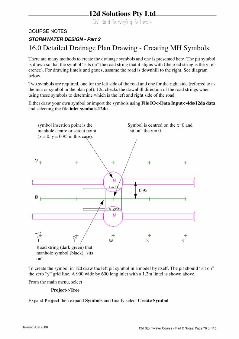
Revised July 2008 12d Stormwater Course - Part 2 Notes: Page 79 of 110
12d Solutions Pty Ltd
COURSE NOTES
STORMWATER DESIGN - Part 2
16.0 Detailed Drainage Plan Drawing - Creating MH Symbols
There are many methods to create the drainage symbols and one is presented here. The pit symbol
is drawn so that the symbol “sits on” the road string that it aligns with (the road string is the y ref-
erence). For drawing lintels and grates, assume the road is downhill to the right. See diagram
below.
Two symbols are required, one for the left side of the road and one for the right side (referred to as
the mirror symbol in the plan ppf). 12d checks the downhill direction of the road strings when
using these symbols to determine which is the left and right side of the road.
Either draw your own symbol or import the symbols using File IO->Data Input->4ds/12da data
and selecting the file inlet symbols.12da
To create the symbol in 12d draw the left pit symbol in a model by itself. The pit should “sit on”
the zero “y” grid line. A 900 wide by 600 long inlet with a 1.2m lintel is shown above.
From the main menu, select
Project->Tree
Expand Project then expand Symbols and finally select Create Symbol.
Road string (dark green) that
manhole symbol (black) “sits
on”.
symbol insertion point is the
manhole centre or setout point
(x = 0, y = 0.95 in this case).
Symbol is centred on the x=0 and
“sit on” the y = 0.
0.95
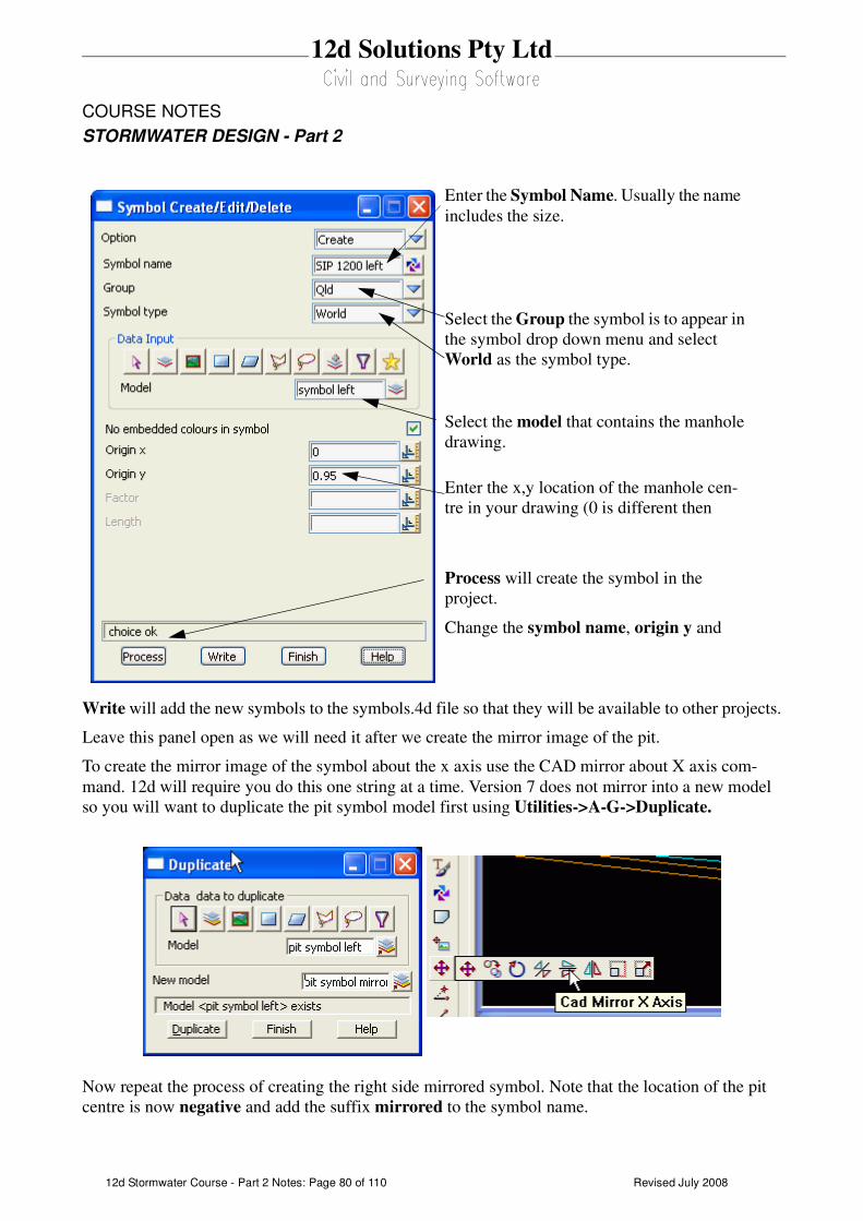
Revised July 200812d Stormwater Course - Part 2 Notes: Page 80 of 110
12d Solutions Pty Ltd
COURSE NOTES
STORMWATER DESIGN - Part 2
Write will add the new symbols to the symbols.4d file so that they will be available to other projects.
Leave this panel open as we will need it after we create the mirror image of the pit.
To create the mirror image of the symbol about the x axis use the CAD mirror about X axis com-
mand. 12d will require you do this one string at a time. Version 7 does not mirror into a new model
so you will want to duplicate the pit symbol model first using Utilities->A-G->Duplicate.
Now repeat the process of creating the right side mirrored symbol. Note that the location of the pit
centre is now negative and add the suffix mirrored to the symbol name.
Enter the Symbol Name. Usually the name
includes the size.
Select the Group the symbol is to appear in
the symbol drop down menu and select
World as the symbol type.
Enter the x,y location of the manhole cen-
tre in your drawing (0 is different then
Select the model that contains the manhole
drawing.
Process will create the symbol in the
project.
Change the symbol name, origin y and

Revised July 2008 12d Stormwater Course - Part 2 Notes: Page 81 of 110
12d Solutions Pty Ltd
COURSE NOTES
STORMWATER DESIGN - Part 2
Do not forget to select Write again to save the symbols to the symbols.4d file.
These symbols can now be used in the Maintenance hole tab of the Drainage Plan Plot ppf editor.
If your version of 12d supports, native-size symbol, in the ppf editor then use this mode. If not,
select scalable symbol and enter the size equal to the full width of the symbol (height if it is
greater).

Revised July 200812d Stormwater Course - Part 2 Notes: Page 82 of 110
12d Solutions Pty Ltd
COURSE NOTES
STORMWATER DESIGN - Part 2
17.0 User Defined Attributes
These drainage attributes are automatically created by 12d when required but you are free to change
them or add more as desired. The attributes may be exported to a spreadsheet and edited and then
imported back into 12d. To edit/add the user defined attributes within 12d select either
Strings=>Properties=>Attributes or
Strings=>User=>Attribute Editor. This second editor is described below.
.
They may not be defined for the pit you are editing. Not found will be displayed in the Data field if
the pit does not have that attribute defined.
To change the value for the attribute enter
the new value in the data field. If the
attribute does not exist, deleting the not
found text and adding data will create it.
The message on the right will be displayed
whenever you are creating a new attribute.
First Select Pick to select the string that
contains the user attributes (the drainage
string). The strings will be highlighted in
white when they are selected.
All catchment data is store with the pits in
drainage strings. To access the pit attributes,
select the drop down icon and then select
pit. A circle will be drawn around the pit
selected. Next and Prev will now move you
from pit to pit.
Select the drop down icon and then select
the Attribute Name from the list of existing
user defined attributes. These attributes
include all of the attributes in the model that
the string exists in.
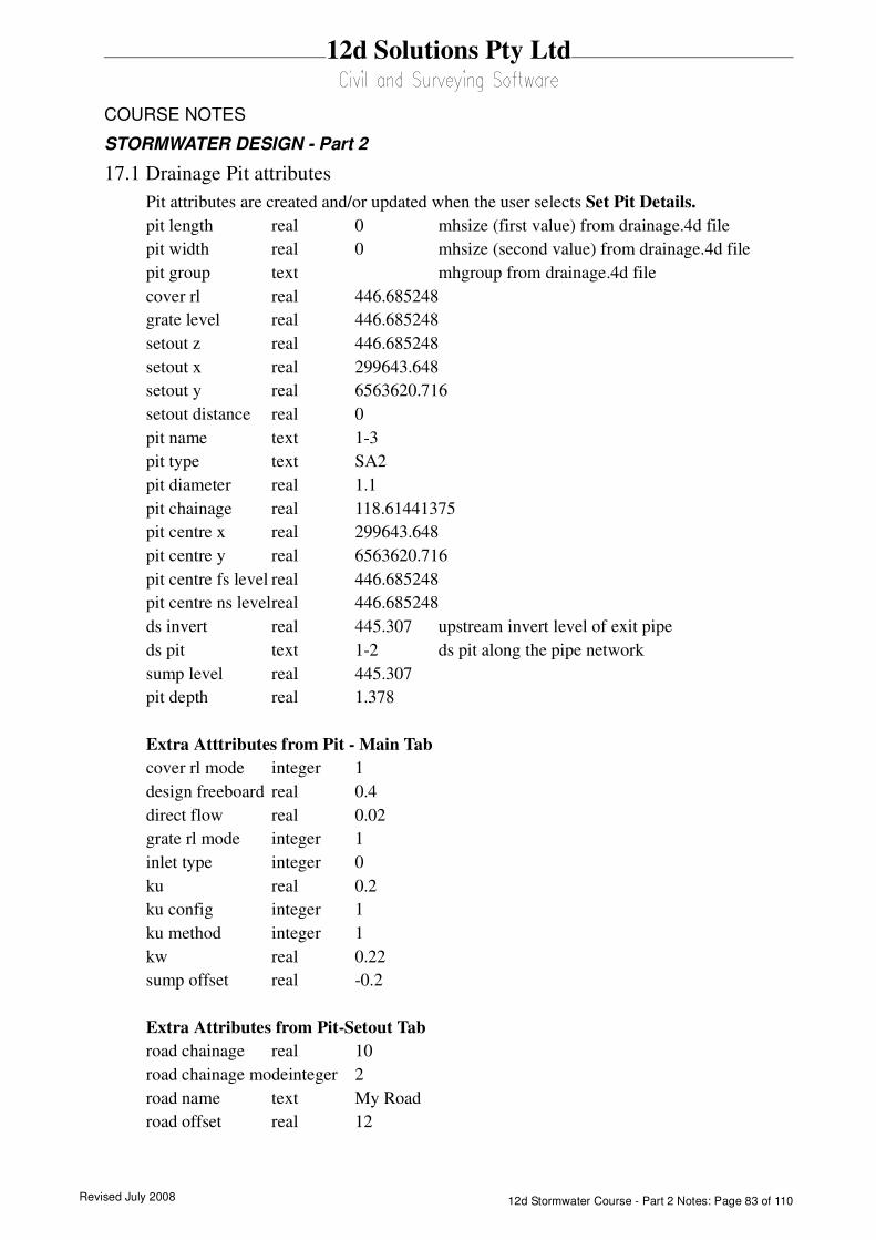
Revised July 2008 12d Stormwater Course - Part 2 Notes: Page 83 of 110
12d Solutions Pty Ltd
COURSE NOTES
STORMWATER DESIGN - Part 2
17.1 Drainage Pit attributes
Pit attributes are created and/or updated when the user selects Set Pit Details.
pit length real 0 mhsize (first value) from drainage.4d file
pit width real 0 mhsize (second value) from drainage.4d file
pit group text mhgroup from drainage.4d file
cover rl real 446.685248
grate level real 446.685248
setout z real 446.685248
setout x real 299643.648
setout y real 6563620.716
setout distance real 0
pit name text 1-3
pit type text SA2
pit diameter real 1.1
pit chainage real 118.61441375
pit centre x real 299643.648
pit centre y real 6563620.716
pit centre fs level real 446.685248
pit centre ns levelreal 446.685248
ds invert real 445.307 upstream invert level of exit pipe
ds pit text 1-2 ds pit along the pipe network
sump level real 445.307
pit depth real 1.378
Extra Atttributes from Pit - Main Tab
cover rl mode integer 1
design freeboard real 0.4
direct flow real 0.02
grate rl mode integer 1
inlet type integer 0
ku real 0.2
ku config integer 1
ku method integer 1
kw real 0.22
sump offset real -0.2
Extra Attributes from Pit-Setout Tab
road chainage real 10
road chainage modeinteger 2
road name text My Road
road offset real 12
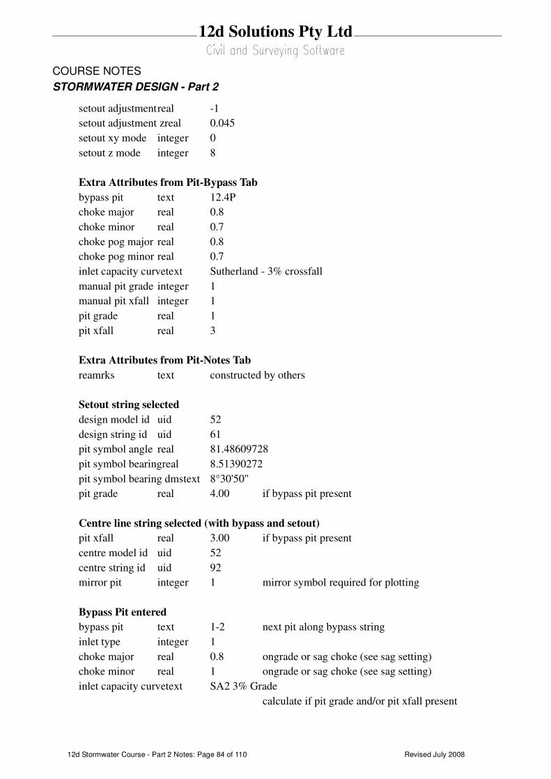
Revised July 200812d Stormwater Course - Part 2 Notes: Page 84 of 110
12d Solutions Pty Ltd
COURSE NOTES
STORMWATER DESIGN - Part 2
setout adjustmentreal -1
setout adjustment zreal 0.045
setout xy mode integer 0
setout z mode integer 8
Extra Attributes from Pit-Bypass Tab
bypass pit text 12.4P
choke major real 0.8
choke minor real 0.7
choke pog major real 0.8
choke pog minor real 0.7
inlet capacity curvetext Sutherland - 3% crossfall
manual pit grade integer 1
manual pit xfall integer 1
pit grade real 1
pit xfall real 3
Extra Attributes from Pit-Notes Tab
reamrks text constructed by others
Setout string selected
design model id uid 52
design string id uid 61
pit symbol angle real 81.48609728
pit symbol bearingreal 8.51390272
pit symbol bearing dmstext 8°30'50"
pit grade real 4.00 if bypass pit present
Centre line string selected (with bypass and setout)
pit xfall real 3.00 if bypass pit present
centre model id uid 52
centre string id uid 92
mirror pit integer 1 mirror symbol required for plotting
Bypass Pit entered
bypass pit text 1-2 next pit along bypass string
inlet type integer 1
choke major real 0.8 ongrade or sag choke (see sag setting)
choke minor real 1 ongrade or sag choke (see sag setting)
inlet capacity curvetext SA2 3% Grade
calculate if pit grade and/or pit xfall present
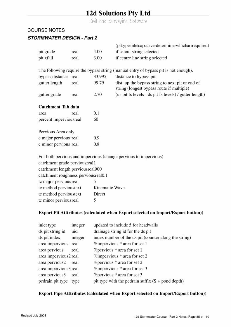
Revised July 2008 12d Stormwater Course - Part 2 Notes: Page 85 of 110
12d Solutions Pty Ltd
COURSE NOTES
STORMWATER DESIGN - Part 2
(pit type - inlet cap curves determines which are required)
pit grade real 4.00 if setout string selected
pit xfall real 3.00 if centre line string selected
The following require the bypass string (manual entry of bypass pit is not enough).
bypass distance real 33.995 distance to bypass pit
gutter length real 99.79 dist. up the bypass string to next pit or end of
string (longest bypass route if multiple)
gutter grade real 2.70 (us pit fs levels - ds pit fs levels) / gutter length)
Catchment Tab data
area real 0.1
percent imperviousreal 60
Pervious Area only
c major pervious real 0.9
c minor pervious real 0.8
For both pervious and impervious (change pervious to impervious)
catchment grade perviousreal1
catchment length perviousreal900
catchment roughness perviousreal0.1
tc major perviousreal 5
tc method pervioustext Kinematic Wave
tc method pervioustext Direct
tc minor perviousreal 5
Export Pit Atttributes (calculated when Export selected on Import/Export button))
inlet type integer updated to include 5 for headwalls
ds pit string id uid drainage string id for the ds pit
ds pit index integer index number of the ds pit (counter along the string)
area impervious real %impervious * area for set 1
area pervious real %pervious * area for set 1
area impervious2 real %impervious * area for set 2
area pervious2 real %pervious * area for set 2
area impervious3 real %impervious * area for set 3
area pervious3 real %pervious * area for set 3
pcdrain pit type type pit type with the pcdrain suffix (S + pond depth)
Export Pipe Atttributes (calculated when Export selected on Import/Export button))
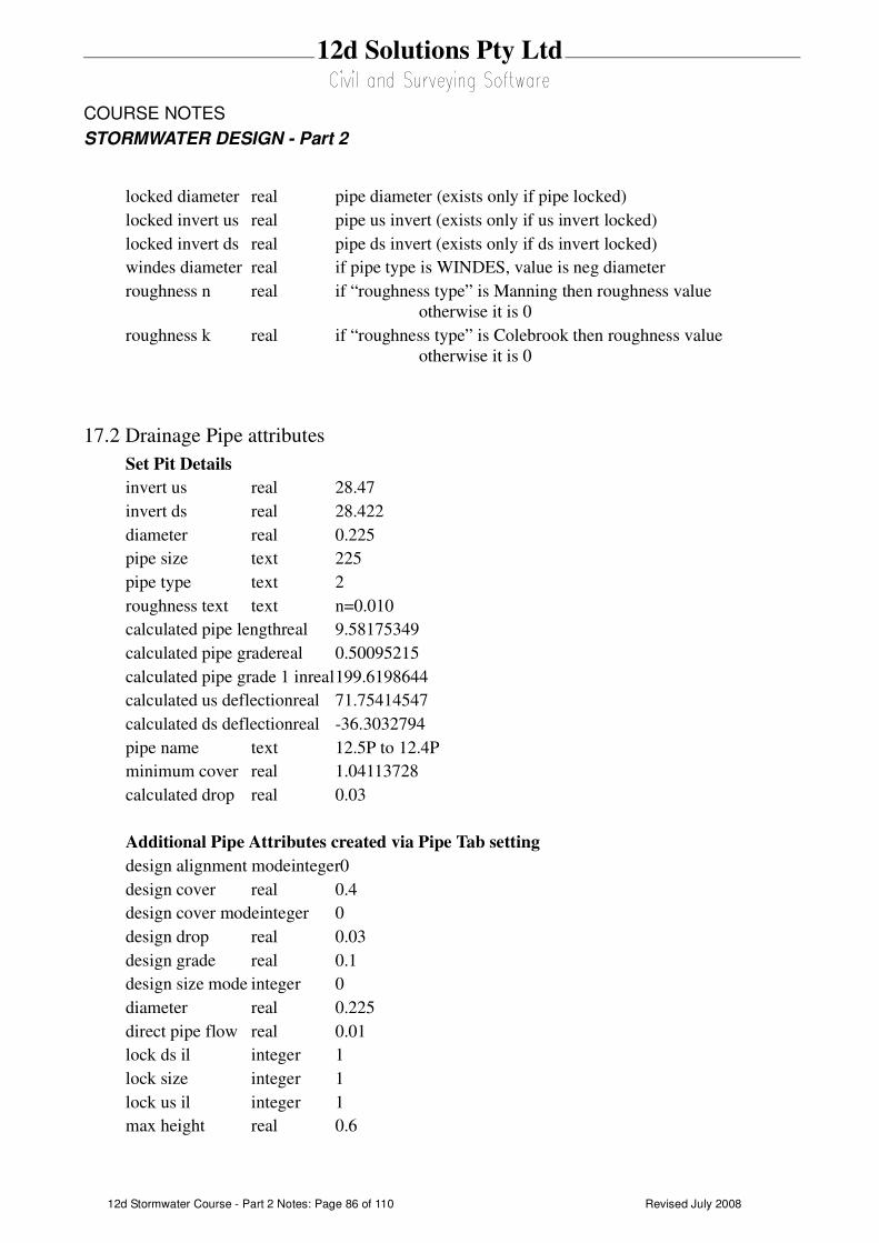
Revised July 200812d Stormwater Course - Part 2 Notes: Page 86 of 110
12d Solutions Pty Ltd
COURSE NOTES
STORMWATER DESIGN - Part 2
locked diameter real pipe diameter (exists only if pipe locked)
locked invert us real pipe us invert (exists only if us invert locked)
locked invert ds real pipe ds invert (exists only if ds invert locked)
windes diameter real if pipe type is WINDES, value is neg diameter
roughness n real if “roughness type” is Manning then roughness value
otherwise it is 0
roughness k real if “roughness type” is Colebrook then roughness value
otherwise it is 0
17.2 Drainage Pipe attributes
Set Pit Details
invert us real 28.47
invert ds real 28.422
diameter real 0.225
pipe size text 225
pipe type text 2
roughness text text n=0.010
calculated pipe lengthreal 9.58175349
calculated pipe gradereal 0.50095215
calculated pipe grade 1 inreal199.6198644
calculated us deflectionreal 71.75414547
calculated ds deflectionreal -36.3032794
pipe name text 12.5P to 12.4P
minimum cover real 1.04113728
calculated drop real 0.03
Additional Pipe Attributes created via Pipe Tab setting
design alignment modeinteger0
design cover real 0.4
design cover modeinteger 0
design drop real 0.03
design grade real 0.1
design size mode integer 0
diameter real 0.225
direct pipe flow real 0.01
lock ds il integer 1
lock size integer 1
lock us il integer 1
max height real 0.6

Revised July 2008 12d Stormwater Course - Part 2 Notes: Page 87 of 110
12d Solutions Pty Ltd
COURSE NOTES
STORMWATER DESIGN - Part 2
min height real 0.3
remarks text extra pipe notes
roughness real 0.012
roughness type text Manning
width real 0.225
width top real 6

Revised July 200812d Stormwater Course - Part 2 Notes: Page 88 of 110
12d Solutions Pty Ltd
COURSE NOTES
STORMWATER DESIGN - Part 2
18.0 Detailed Drainage Plan Drawing
12d drainage has the capability to create detailed drainage plan drawings with the following features:
screate symbols at the inlets and the type of symbol is controlled by the inlet type (given when you create
the inlet).
screate text labels for inlet types and user defined pit attributes
sdraw lines with line styles and colours to represent pipe sizes
screate text labels for pipe diameters, inverts and user defined pipe attributes
screate text labels for house connection types, invert levels and chainages
sindicate direction of flow on pipes.
An example is shown below
Usage
This option is accessed from the menu selection
Design => Drainage-Sewer => Plots => Plan Annotations
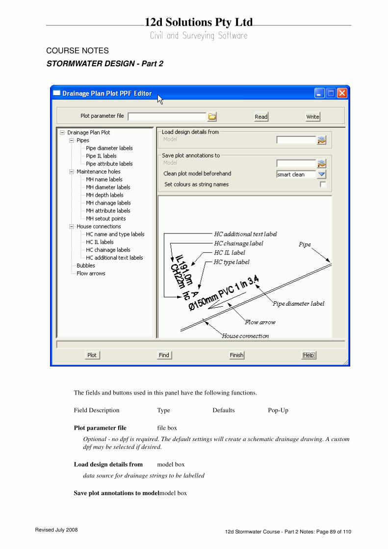
Revised July 2008 12d Stormwater Course - Part 2 Notes: Page 89 of 110
12d Solutions Pty Ltd
COURSE NOTES
STORMWATER DESIGN - Part 2
The fields and buttons used in this panel have the following functions.
Field Description Type Defaults Pop-Up
Plot parameter file file box
Optional - no dpf is required. The default settings will create a schematic drainage drawing. A custom
dpf may be selected if desired.
Load design details from model box
data source for drainage strings to be labelled
Save plot annotations to modelmodel box
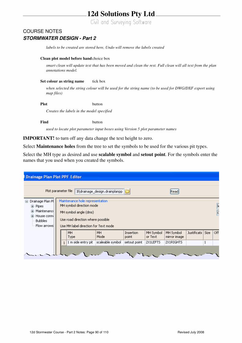
Revised July 200812d Stormwater Course - Part 2 Notes: Page 90 of 110
12d Solutions Pty Ltd
COURSE NOTES
STORMWATER DESIGN - Part 2
labels to be created are stored here, Undo will remove the labels created
Clean plot model before hand choice box
smart clean will update text that has been moved and clean the rest. Full clean will all text from the plan
annotations model.
Set colour as string name tick box
when selected the string colour will be used for the string name (to be used for DWG/DXF export using
map files)
Plot button
Creates the labels in the model specified
Find button
used to locate plot parameter input boxes using Version 5 plot parameter names
IMPORTANT! to turn off any data change the text height to zero.
Select Maintenance holes from the tree to set the symbols to be used for the various pit types.
Select the MH type as desired and use scalable symbol and setout point. For the symbols enter the
names that you used when you created the symbols.
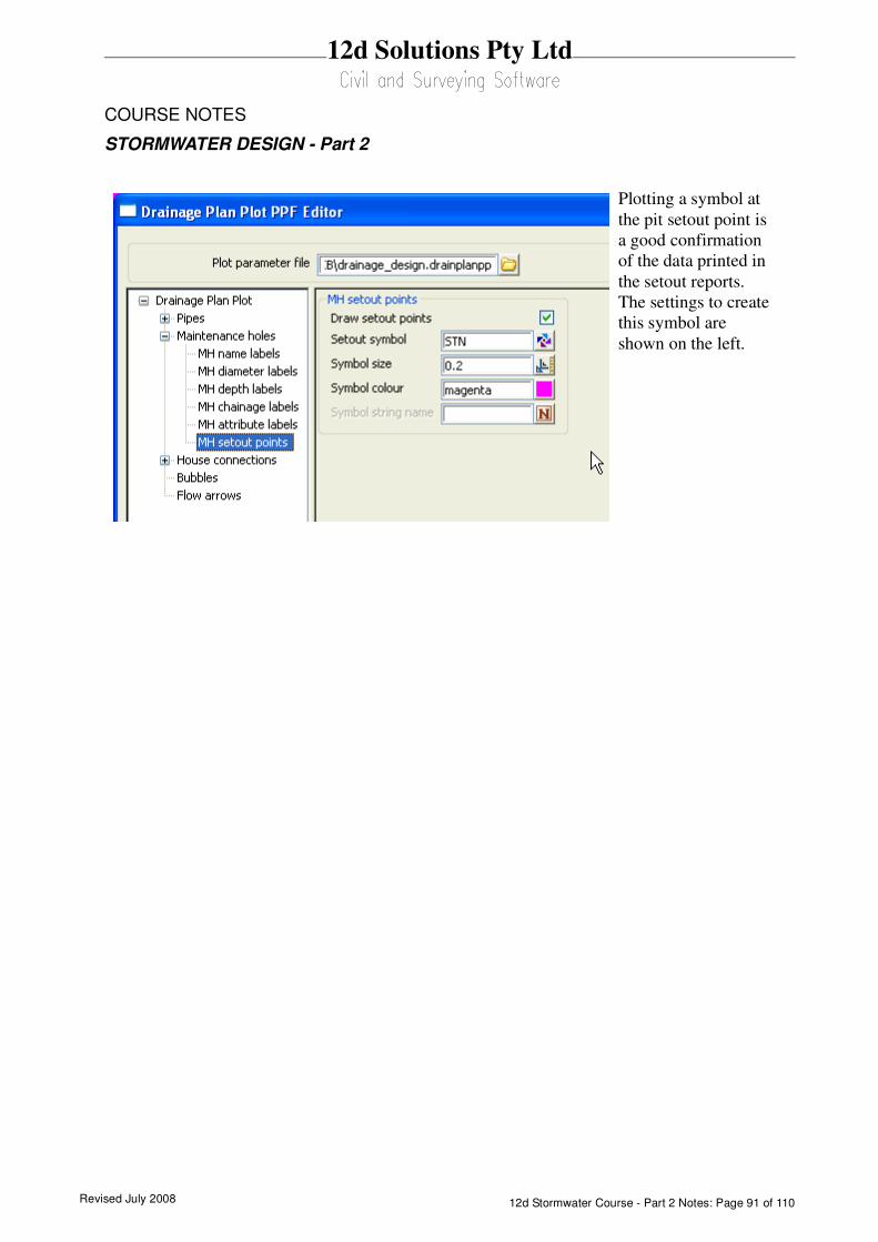
Revised July 2008 12d Stormwater Course - Part 2 Notes: Page 91 of 110
12d Solutions Pty Ltd
COURSE NOTES
STORMWATER DESIGN - Part 2
Plotting a symbol at
the pit setout point is
a good confirmation
of the data printed in
the setout reports.
The settings to create
this symbol are
shown on the left.
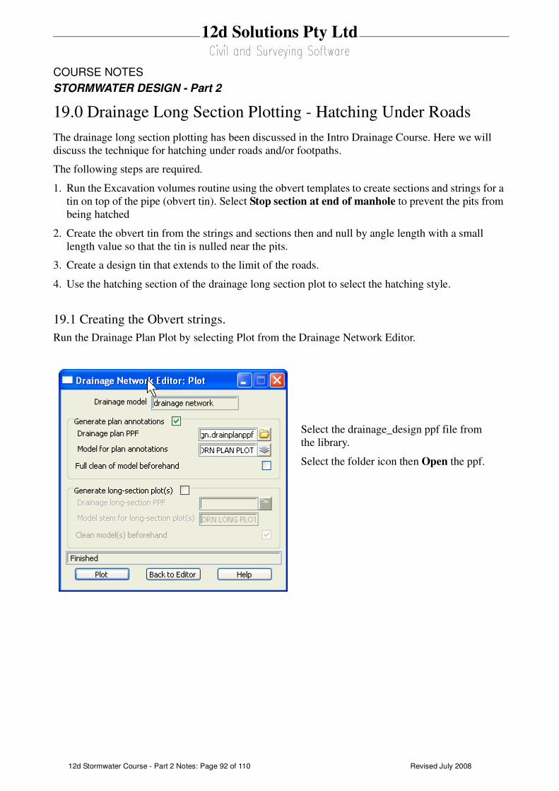
Revised July 200812d Stormwater Course - Part 2 Notes: Page 92 of 110
12d Solutions Pty Ltd
COURSE NOTES
STORMWATER DESIGN - Part 2
19.0 Drainage Long Section Plotting - Hatching Under Roads
The drainage long section plotting has been discussed in the Intro Drainage Course. Here we will
discuss the technique for hatching under roads and/or footpaths.
The following steps are required.
1. Run the Excavation volumes routine using the obvert templates to create sections and strings for a
tin on top of the pipe (obvert tin). Select Stop section at end of manhole to prevent the pits from
being hatched
2. Create the obvert tin from the strings and sections then and null by angle length with a small
length value so that the tin is nulled near the pits.
3. Create a design tin that extends to the limit of the roads.
4. Use the hatching section of the drainage long section plot to select the hatching style.
19.1 Creating the Obvert strings.
Run the Drainage Plan Plot by selecting Plot from the Drainage Network Editor.
Select the drainage_design ppf file from
the library.
Select the folder icon then Open the ppf.
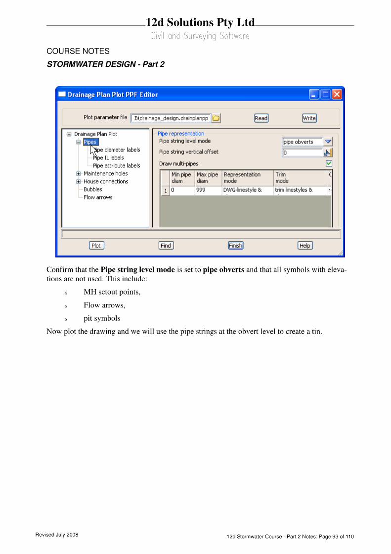
Revised July 2008 12d Stormwater Course - Part 2 Notes: Page 93 of 110
12d Solutions Pty Ltd
COURSE NOTES
STORMWATER DESIGN - Part 2
Confirm that the Pipe string level mode is set to pipe obverts and that all symbols with eleva-
tions are not used. This include:
s MH setout points,
s Flow arrows,
s pit symbols
Now plot the drawing and we will use the pipe strings at the obvert level to create a tin.

Revised July 200812d Stormwater Course - Part 2 Notes: Page 94 of 110
12d Solutions Pty Ltd
COURSE NOTES
STORMWATER DESIGN - Part 2
19.2 Create and Null the Obvert tin
To create the obvert tin select.
Tins->Create->Triangulate Data
Enter a New tin name as desired.
Select the Nulling tab
Enter a Length that is less than the pit
diameter and greater than the largest pipe.
Select Triangulate
Select the Data tab.
Select the plot model created above.

Revised July 2008 12d Stormwater Course - Part 2 Notes: Page 95 of 110
12d Solutions Pty Ltd
COURSE NOTES
STORMWATER DESIGN - Part 2
The tin will now only exist on top of the pipe and it is ready to use for hatching.
19.3 Create a Roads Only Tin
The design tin is already nulled to remove the long triangles. If the footpaths were to be excluded
from the tin then they should be removed from the road design strings. You could run a template
that did not include the footpath and has a Final Maximum slope width of zero or just copy the
desired road strings to one model and remove unwanted strings. We will use the later techniques.
Add all of the road string and kerb return models onto one view and then select
Utilities->A-G->Change
View select the view that contains all of the road
strings
Copy to model type the name of a model for all of
the road strings.
Select Change copy the strings.
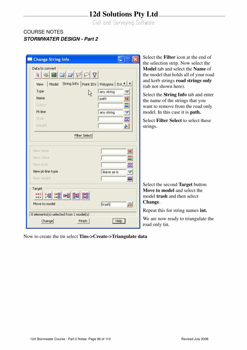
Revised July 200812d Stormwater Course - Part 2 Notes: Page 96 of 110
12d Solutions Pty Ltd
COURSE NOTES
STORMWATER DESIGN - Part 2
Now to create the tin select Tins->Create->Triangulate data
Select the Filter icon at the end of
the selection strip. Now select the
Model tab and select the Name of
the model that holds all of your road
and kerb strings road strings only
(tab not shown here).
Select the String Info tab and enter
the name of the strings that you
want to remove from the road only
model. In this case it is path.
Select Filter Select to select these
strings.
Select the second Target button
Move to model and select the
model trash and then select
Change.
Repeat this for string names int.
We are now ready to triangulate the
road only tin.
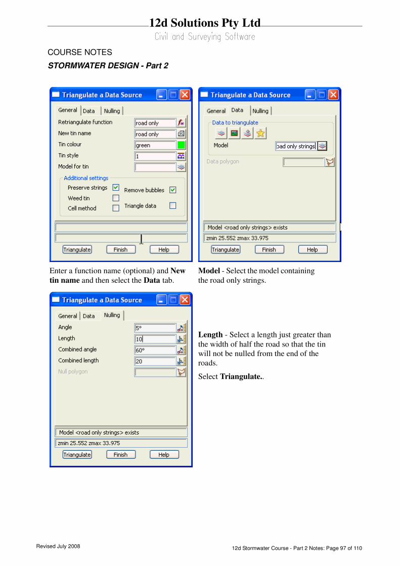
Revised July 2008 12d Stormwater Course - Part 2 Notes: Page 97 of 110
12d Solutions Pty Ltd
COURSE NOTES
STORMWATER DESIGN - Part 2
Model - Select the model containing
the road only strings.
Enter a function name (optional) and New
tin name and then select the Data tab.
Length - Select a length just greater than
the width of half the road so that the tin
will not be nulled from the end of the
roads.
Select Triangulate..
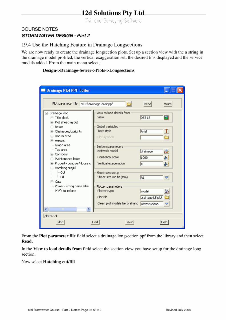
Revised July 200812d Stormwater Course - Part 2 Notes: Page 98 of 110
12d Solutions Pty Ltd
COURSE NOTES
STORMWATER DESIGN - Part 2
19.4 Use the Hatching Feature in Drainage Longsections
We are now ready to create the drainage longsection plots. Set up a section view with the a string in
the drainage model profiled, the vertical exaggeration set, the desired tins displayed and the service
models added. From the main menu select,
Design->Drainage-Sewer->Plots->Longsections
From the Plot parameter file field select a drainage longsection ppf from the library and then select
Read.
In the View to load details from field select the section view you have setup for the drainage long
section.
Now select Hatching cut/fill
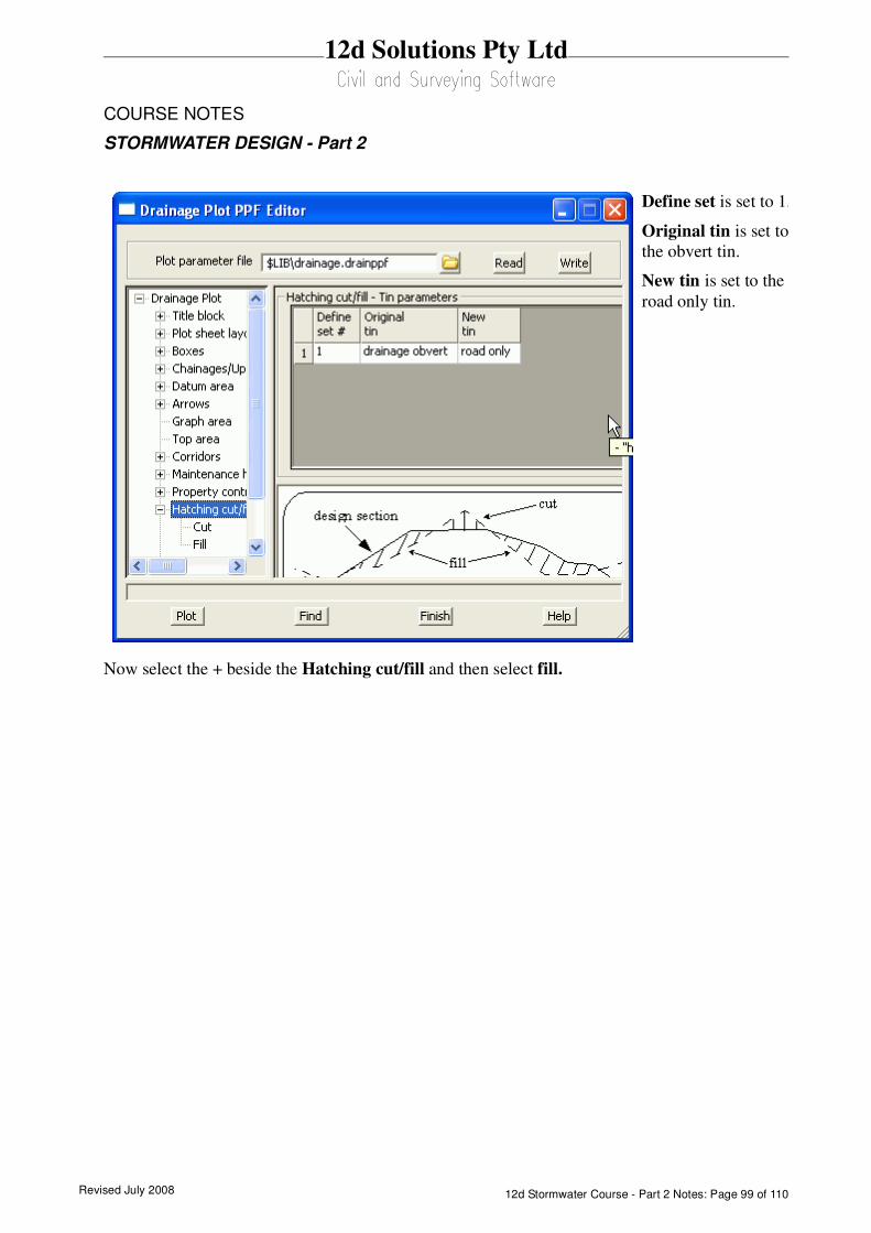
Revised July 2008 12d Stormwater Course - Part 2 Notes: Page 99 of 110
12d Solutions Pty Ltd
COURSE NOTES
STORMWATER DESIGN - Part 2
Now select the + beside the Hatching cut/fill and then select fill.
Define set is set to 1.
Original tin is set to
the obvert tin.
New tin is set to the
road only tin.
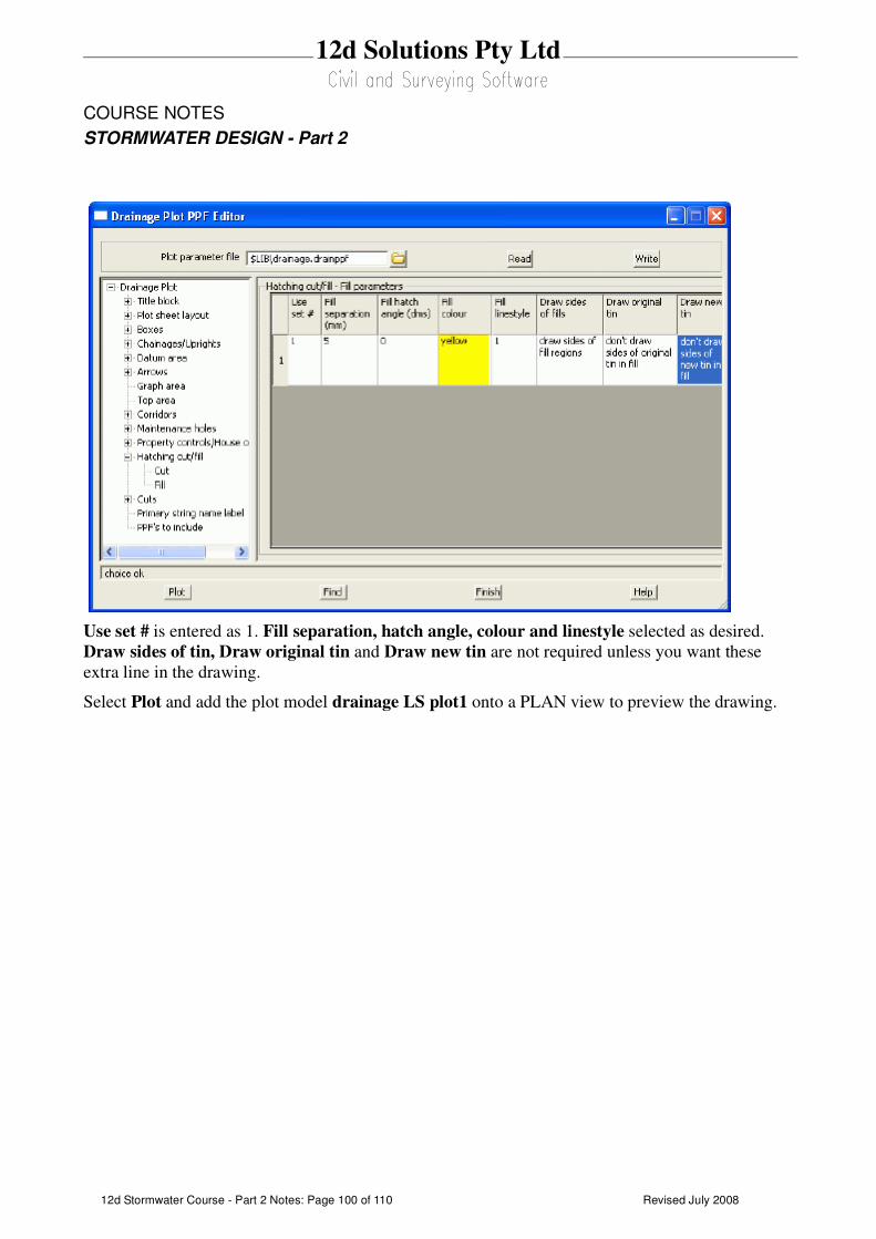
Revised July 200812d Stormwater Course - Part 2 Notes: Page 100 of 110
12d Solutions Pty Ltd
COURSE NOTES
STORMWATER DESIGN - Part 2
Use set # is entered as 1. Fill separation, hatch angle, colour and linestyle selected as desired.
Draw sides of tin, Draw original tin and Draw new tin are not required unless you want these
extra line in the drawing.
Select Plot and add the plot model drainage LS plot1 onto a PLAN view to preview the drawing.
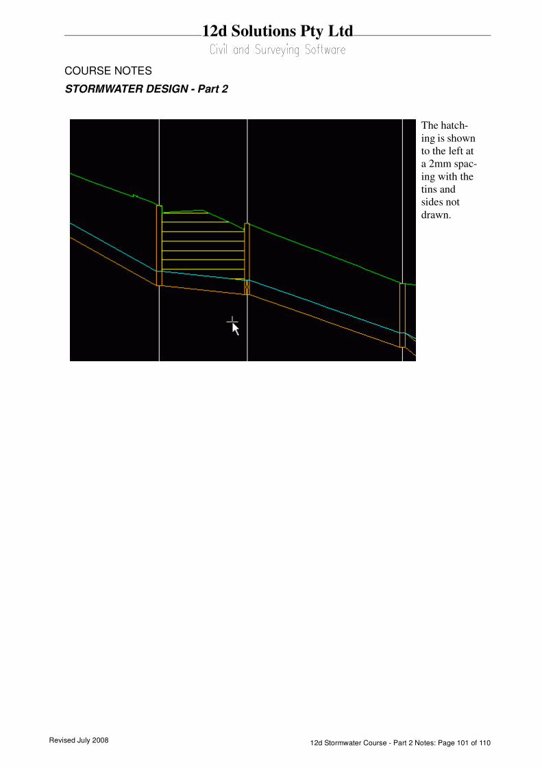
Revised July 2008 12d Stormwater Course - Part 2 Notes: Page 101 of 110
12d Solutions Pty Ltd
COURSE NOTES
STORMWATER DESIGN - Part 2
The hatch-
ing is shown
to the left at
a 2mm spac-
ing with the
tins and
sides not
drawn.
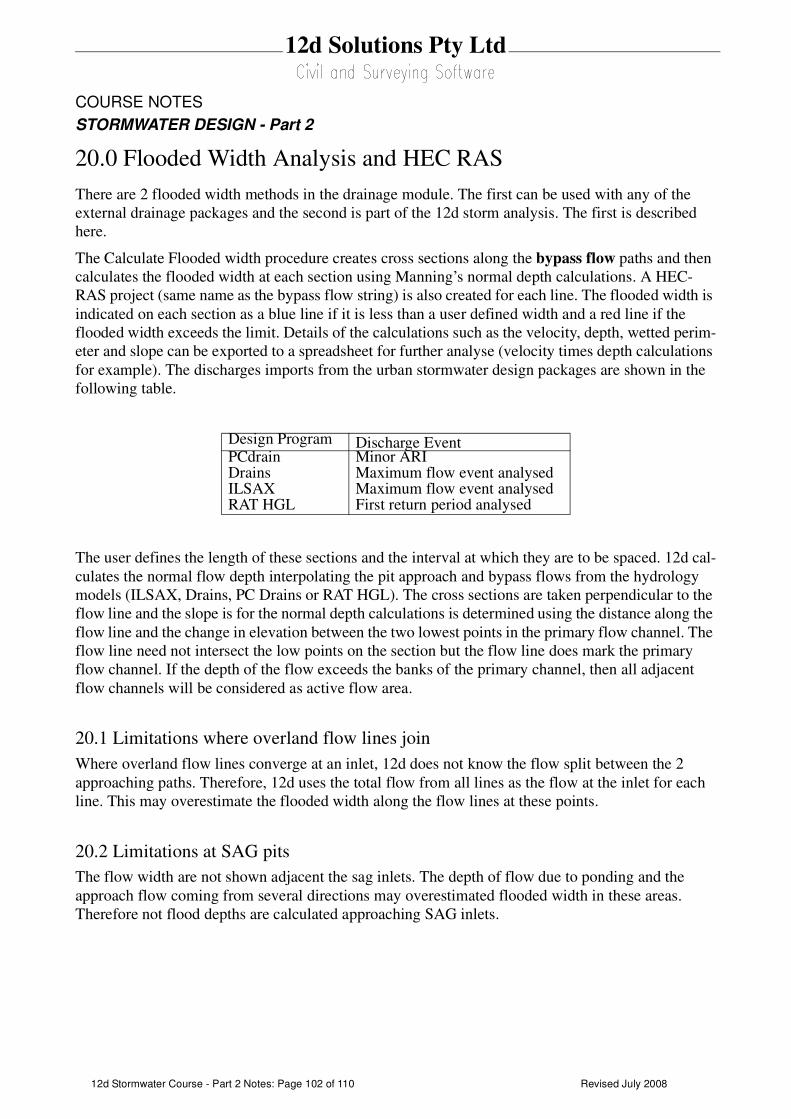
Revised July 200812d Stormwater Course - Part 2 Notes: Page 102 of 110
12d Solutions Pty Ltd
COURSE NOTES
STORMWATER DESIGN - Part 2
20.0 Flooded Width Analysis and HEC RAS
There are 2 flooded width methods in the drainage module. The first can be used with any of the
external drainage packages and the second is part of the 12d storm analysis. The first is described
here.
The Calculate Flooded width procedure creates cross sections along the bypass flow paths and then
calculates the flooded width at each section using Manning’s normal depth calculations. A HEC-
RAS project (same name as the bypass flow string) is also created for each line. The flooded width is
indicated on each section as a blue line if it is less than a user defined width and a red line if the
flooded width exceeds the limit. Details of the calculations such as the velocity, depth, wetted perim-
eter and slope can be exported to a spreadsheet for further analyse (velocity times depth calculations
for example). The discharges imports from the urban stormwater design packages are shown in the
following table.
The user defines the length of these sections and the interval at which they are to be spaced. 12d cal-
culates the normal flow depth interpolating the pit approach and bypass flows from the hydrology
models (ILSAX, Drains, PC Drains or RAT HGL). The cross sections are taken perpendicular to the
flow line and the slope is for the normal depth calculations is determined using the distance along the
flow line and the change in elevation between the two lowest points in the primary flow channel. The
flow line need not intersect the low points on the section but the flow line does mark the primary
flow channel. If the depth of the flow exceeds the banks of the primary channel, then all adjacent
flow channels will be considered as active flow area.
20.1 Limitations where overland flow lines join
Where overland flow lines converge at an inlet, 12d does not know the flow split between the 2
approaching paths. Therefore, 12d uses the total flow from all lines as the flow at the inlet for each
line. This may overestimate the flooded width along the flow lines at these points.
20.2 Limitations at SAG pits
The flow width are not shown adjacent the sag inlets. The depth of flow due to ponding and the
approach flow coming from several directions may overestimated flooded width in these areas.
Therefore not flood depths are calculated approaching SAG inlets.
Design Program Discharge EventPCdrain Minor ARIDrains Maximum flow event analysedILSAX Maximum flow event analysedRAT HGL First return period analysed

Revised July 2008 12d Stormwater Course - Part 2 Notes: Page 103 of 110
12d Solutions Pty Ltd
COURSE NOTES
STORMWATER DESIGN - Part 2
Trim sections at levee is used to create a cross section that stops at the crest on either side of the
flow channel. A levee point is the crest in the cross section found as you move away from the
flow line location. If a levee point is encountered then the section is trimmed here.
Levee tolerance is the amount the cross section needs to drop as you move away from the centre
line in order to call this local crest a levee.
VxD warning limit is the velocity times depth limit that when exceeded will cause a flooded
Enter the drainage network model.
Enter the bypass flow model.
Enter the model that will contain the actual flooded
width lines.
Select the tin that will be used to create the cross
sections.
Enter the model that will contain the cross sections.
The calculated values such as velocity and slope
are stored with these lines.
The flooded width will be drawn in blue in the
results model when it is less than the Max flooded
width (Variables tab). If the flooded width exceeds
this value it will be drawn in red.
If warnings are give for a section a yellow bar will
be placed in this model.
Max flooded width is the limit where the blue
flooded width bars turn red.
Manning’s n is the n value to be used in the normal
depth calculations.
The Flow correction factor is the factor described in
ARR 1987 for calculating depths of flow in gutter
channels.
Distance between sections specifies the interval at
which cross sections and therefore flooded width will
be calculated along the flow path.
Section Length defines the length of each cross sec-
tion. The cross section will be centred on the over-
land flow path.
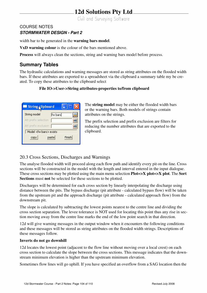
Revised July 200812d Stormwater Course - Part 2 Notes: Page 104 of 110
12d Solutions Pty Ltd
COURSE NOTES
STORMWATER DESIGN - Part 2
width bar to be generated in the warning bars model.
VxD warning colour is the colour of the bars mentioned above.
Process will always clean the sections, string and warning bars model before process.
Summary Tables
The hydraulic calculations and warning messages are stored as string attributes on the flooded width
bars. If these attributes are exported to a spreadsheet via the clipboard a summary table my be cre-
ated. To copy these attributes to the clipboard select
File IO->User->String attributes-properties to/from clipboard
20.3 Cross Sections, Discharges and Warnings
The analyse flooded width will proceed along each flow path and identify every pit on the line. Cross
sections will be constructed in the model with the length and interval entered in the input dialogue.
These cross sections may be plotted using the main menu selection Plot=>X plot=>X plot. The Sort
Sections must not be selected for these sections to be plotted.
Discharges will be determined for each cross section by linearly interpolating the discharge using
distance between the pits. The bypass discharge (pit attribute - calculated bypass flow) will be taken
from the upstream pit and the approach discharge (pit attribute - calculated approach flow) from the
downstream pit.
The slope is calculated by subtracting the lowest points nearest to the centre line and dividing the
cross section separation. The levee tolerance is NOT used for locating this point thus any rise in sec-
tion moving away from the centre line marks the end of the low point search in that direction.
12d will give warning messages in the output window when it encounters the following conditions
and these messages will be stored as string attributes on the flooded width strings. Descriptions of
these messages follow.
Inverts do not go downhill
12d locates the lowest point (adjacent to the flow line without moving over a local crest) on each
cross section to calculate the slope between the cross sections. This message indicates that the down-
stream minimum elevation is higher than the upstream minimum elevation.
Sometimes flow lines will go uphill. If you have specified an overflow from a SAG location then the
The string model may be either the flooded width bars
or the warning bars. Both models of strings contain
attributes on the strings.
The prefix selection and prefix exclusion are filters for
reducing the number attributes that are exported to the
clipboard.
Revised July 2008 12d Stormwater Course - Part 2 Notes: Page 105 of 110
12d Solutions Pty Ltd
COURSE NOTES
STORMWATER DESIGN - Part 2
flow line will go uphill until it crosses the overflow crest.
If the flow line is not supposed to be going uphill at this section, check to see where the flow line
intersects the cross section located upstream of the one identified in the warning message. If it is
in a local sag point that is not the lowest point on the section, move the flow line.
The program will use a slope of 0.5% to calculate a width at this location. This results in very
wide flooded width sections to draw the user’s attention to the problem area.
Vertical Walls Assumed at the Ends of the Cross Sections
If the depth of flow exceeds the ground surface elevation at the ends of the cross section a warn-
ing message the warning message shown above is shown. The cross sections causing the warning
follows.
The vertical wall is placed at cross section chainage –20. Note that the flow line is always at
chainage 0

Revised July 200812d Stormwater Course - Part 2 Notes: Page 106 of 110
12d Solutions Pty Ltd
COURSE NOTES
STORMWATER DESIGN - Part 2
21.0 Drainage Overflow Areas from Volumes
This option is used to graphically display the overflow storage volume at a sag pit. The following pit
attributes must exist for the flood extents to be calculated.
overflow volume value greater than zero required.
sag pit must be equal to 1.
catchment model id set by labelling catchments
catchment string id set by labelling catchments
The maximum storage volume is read from the drainage pit attribute "overflow volume". This may
be entered manually using the Attribute Editor or it will be created when data is read from the drain-
age design programs Drains or XP SWMM design programs.
This routine locates the lowest point on the catchment string by draping the string on the tin specified
and adds the overflow limit specified to this value. This becomes the overflow limit.
The volume at this level is calculated and the compared to the overflow volume read from the user
defined attribute.If the overflow volume is less than the volume in the catchment then the routine
iterates to find the flood level for the overflow volume.
If the overflow volume is greater than the volume in the catchment, the results depend on the Use
overflow limit tick box.
If the box is selected, the overflow limit (calculated above) is reported at the flood level in the catch-
ment.
If the tick box is not selected the routine iterates to find the flood level where the storage equals the
overflow volume read. This option allows the user to see the maximum flood level should the catch-
ment low point become blocked.
See Also
Drainage overview
Usage
This panel is accessed from the menu selection Design => Drainage Sewer => More=>Calc pit
overflow areas
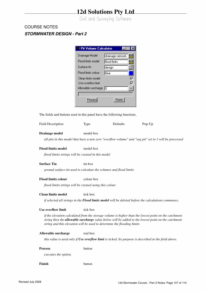
Revised July 2008 12d Stormwater Course - Part 2 Notes: Page 107 of 110
12d Solutions Pty Ltd
COURSE NOTES
STORMWATER DESIGN - Part 2
The fields and buttons used in this panel have the following functions.
Field Description Type Defaults Pop-Up
Drainage model model box
all pits in this model that have a non zero "overflow volume" and "sag pit" set to 1 will be processed
Flood limits model model box
flood limits strings will be created in this model
Surface Tin tin box
ground surface tin used to calculate the volumes and flood limits
Flood limits colour colour box
flood limits strings will be created using this colour
Clean limits model tick box
if selected all strings in the Flood limits model will be deleted before the calculations commence.
Use overflow limit tick box
if the elevation calculated from the storage volume is higher than the lowest point on the catchment
string then the allowable surcharge value below will be added to the lowest point on the catchment
string and this elevation will be used to determine the flooding limits
Allowable surcharge real box
this value is used only if Use overflow limit is ticked. Its purpose is described in the field above.
Process button
executes the option.
Finish button

Revised July 200812d Stormwater Course - Part 2 Notes: Page 108 of 110
12d Solutions Pty Ltd
COURSE NOTES
STORMWATER DESIGN - Part 2
removes the dialogue from the screen

Revised July 2008 12d Stormwater Course - Part 2 Notes: Page 109 of 110
12d Solutions Pty Ltd
COURSE NOTES
STORMWATER DESIGN - Part 2
22.0 Appendices
22.1 Appendix A: 12d V8 Drainage Analysis Detention Basins
22.2 Appendix B: 12d V8 Drainage Analysis Hydraulics
22.3 Appendix C: 12d V8 Drainage Analysis Ku Kw

Revised July 200812d Stormwater Course - Part 2 Notes: Page 110 of 110
12d Solutions Pty Ltd
COURSE NOTES
STORMWATER DESIGN - Part 2
Page 1 of 5
12d Model Civil and Surveying Software
Drainage Analysis Module
Detention/Retention Basins
Owen Thornton BE (Mech), 12d Model Programmer
24 January 2007
Revised:
04 April 2007
29 February 2008 (V8C1p)
This document describes the approximate method
for sizing detention basins via the Rational Method,
as implemented in the
Drainage Analysis module of 12d Model.
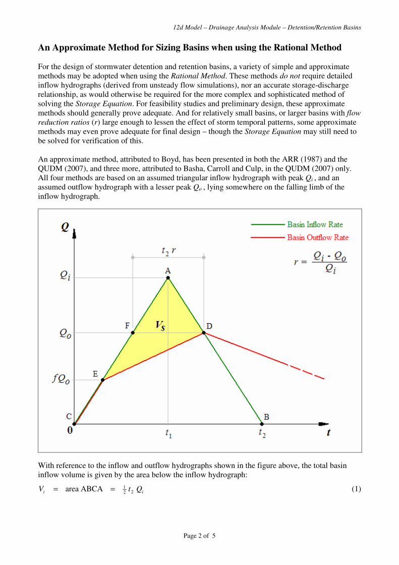
12d Model – Drainage Analysis Module – Detention/Retention Basins
Page 2 of 5
An Approximate Method for Sizing Basins when using the Rational Method
For the design of stormwater detention and retention basins, a variety of simple and approximate
methods may be adopted when using the Rational Method. These methods do not require detailed
inflow hydrographs (derived from unsteady flow simulations), nor an accurate storage-discharge
relationship, as would otherwise be required for the more complex and sophisticated method of
solving the Storage Equation. For feasibility studies and preliminary design, these approximate
methods should generally prove adequate. And for relatively small basins, or larger basins with flow
reduction ratios (r) large enough to lessen the effect of storm temporal patterns, some approximate
methods may even prove adequate for final design – though the Storage Equation may still need to
be solved for verification of this.
An approximate method, attributed to Boyd, has been presented in both the ARR (1987) and the
QUDM (2007), and three more, attributed to Basha, Carroll and Culp, in the QUDM (2007) only.
All four methods are based on an assumed triangular inflow hydrograph with peak Qi , and an
assumed outflow hydrograph with a lesser peak Qo , lying somewhere on the falling limb of the
inflow hydrograph.
With reference to the inflow and outflow hydrographs shown in the figure above, the total basin
inflow volume is given by the area below the inflow hydrograph:
ii QtV 221ABCA area == (1)
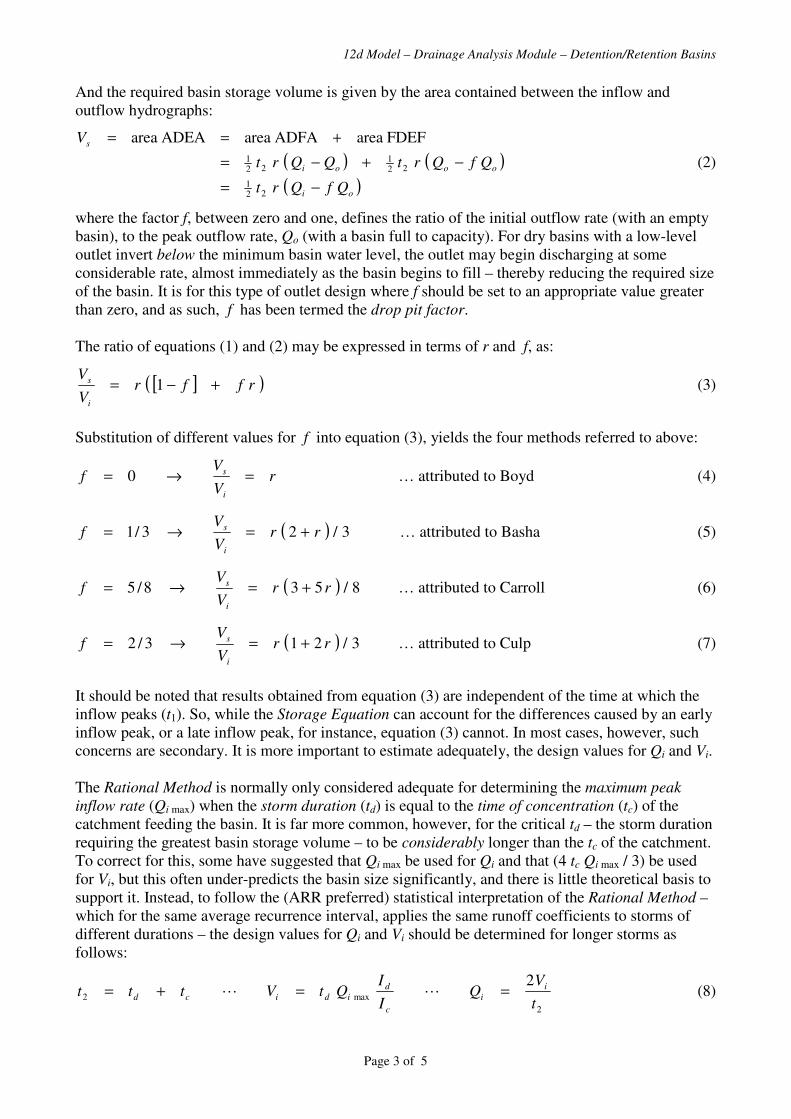
12d Model – Drainage Analysis Module – Detention/Retention Basins
Page 3 of 5
And the required basin storage volume is given by the area contained between the inflow and
outflow hydrographs:
( ) ( )
( )oi
oooi
s
QfQrt
QfQrtQQrt
V
−=
−+−=
+==
221
221
221
FDEF areaADFA areaADEA area
(2)
where the factor f, between zero and one, defines the ratio of the initial outflow rate (with an empty
basin), to the peak outflow rate, Qo (with a basin full to capacity). For dry basins with a low-level
outlet invert below the minimum basin water level, the outlet may begin discharging at some
considerable rate, almost immediately as the basin begins to fill – thereby reducing the required size
of the basin. It is for this type of outlet design where f should be set to an appropriate value greater
than zero, and as such, f has been termed the drop pit factor.
The ratio of equations (1) and (2) may be expressed in terms of r and f, as:
[ ]( )rffrV
V
i
s +−= 1 (3)
Substitution of different values for f into equation (3), yields the four methods referred to above:
rV
Vf
i
s =→= 0 … attributed to Boyd (4)
( ) 3/23/1 rrV
Vf
i
s +=→= … attributed to Basha (5)
( ) 8/538/5 rrV
Vf
i
s +=→= … attributed to Carroll (6)
( ) 3/213/2 rrV
Vf
i
s +=→= … attributed to Culp (7)
It should be noted that results obtained from equation (3) are independent of the time at which the
inflow peaks (t1). So, while the Storage Equation can account for the differences caused by an early
inflow peak, or a late inflow peak, for instance, equation (3) cannot. In most cases, however, such
concerns are secondary. It is more important to estimate adequately, the design values for Qi and Vi.
The Rational Method is normally only considered adequate for determining the maximum peak
inflow rate (Qi max) when the storm duration (td) is equal to the time of concentration (tc) of the
catchment feeding the basin. It is far more common, however, for the critical td – the storm duration
requiring the greatest basin storage volume – to be considerably longer than the tc of the catchment.
To correct for this, some have suggested that Qi max be used for Qi and that (4 tc Qi max / 3) be used
for Vi, but this often under-predicts the basin size significantly, and there is little theoretical basis to
support it. Instead, to follow the (ARR preferred) statistical interpretation of the Rational Method –
which for the same average recurrence interval, applies the same runoff coefficients to storms of
different durations – the design values for Qi and Vi should be determined for longer storms as
follows:
2
max2
2
t
VQ
I
IQtVttt i
i
c
d
idicd ==+= �� (8)
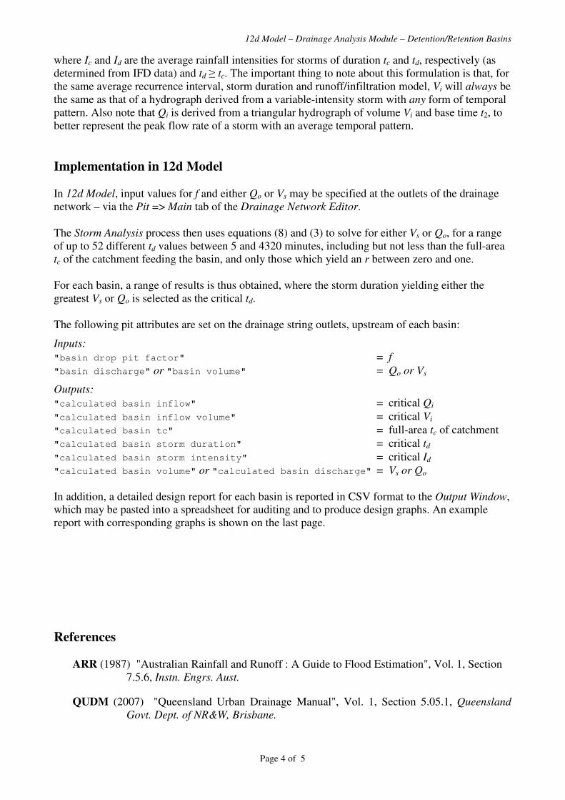
12d Model – Drainage Analysis Module – Detention/Retention Basins
Page 4 of 5
where Ic and Id are the average rainfall intensities for storms of duration tc and td, respectively (as
determined from IFD data) and td � tc. The important thing to note about this formulation is that, for
the same average recurrence interval, storm duration and runoff/infiltration model, Vi will always be
the same as that of a hydrograph derived from a variable-intensity storm with any form of temporal
pattern. Also note that Qi is derived from a triangular hydrograph of volume Vi and base time t2, to
better represent the peak flow rate of a storm with an average temporal pattern.
Implementation in 12d Model
In 12d Model, input values for f and either Qo or Vs may be specified at the outlets of the drainage
network – via the Pit => Main tab of the Drainage Network Editor.
The Storm Analysis process then uses equations (8) and (3) to solve for either Vs or Qo, for a range
of up to 52 different td values between 5 and 4320 minutes, including but not less than the full-area
tc of the catchment feeding the basin, and only those which yield an r between zero and one.
For each basin, a range of results is thus obtained, where the storm duration yielding either the
greatest Vs or Qo is selected as the critical td.
The following pit attributes are set on the drainage string outlets, upstream of each basin:
Inputs:
"basin drop pit factor" = f
"basin discharge" or "basin volume" = Qo or Vs
Outputs:
"calculated basin inflow" = critical Qi
"calculated basin inflow volume" = critical Vi
"calculated basin tc" = full-area tc of catchment
"calculated basin storm duration" = critical td
"calculated basin storm intensity" = critical Id
"calculated basin volume" or "calculated basin discharge" = Vs or Qo
In addition, a detailed design report for each basin is reported in CSV format to the Output Window,
which may be pasted into a spreadsheet for auditing and to produce design graphs. An example
report with corresponding graphs is shown on the last page.
References ARR (1987) "Australian Rainfall and Runoff : A Guide to Flood Estimation", Vol. 1, Section
7.5.6, Instn. Engrs. Aust.
QUDM (2007) "Queensland Urban Drainage Manual", Vol. 1, Section 5.05.1, Queensland
Govt. Dept. of NR&W, Brisbane.
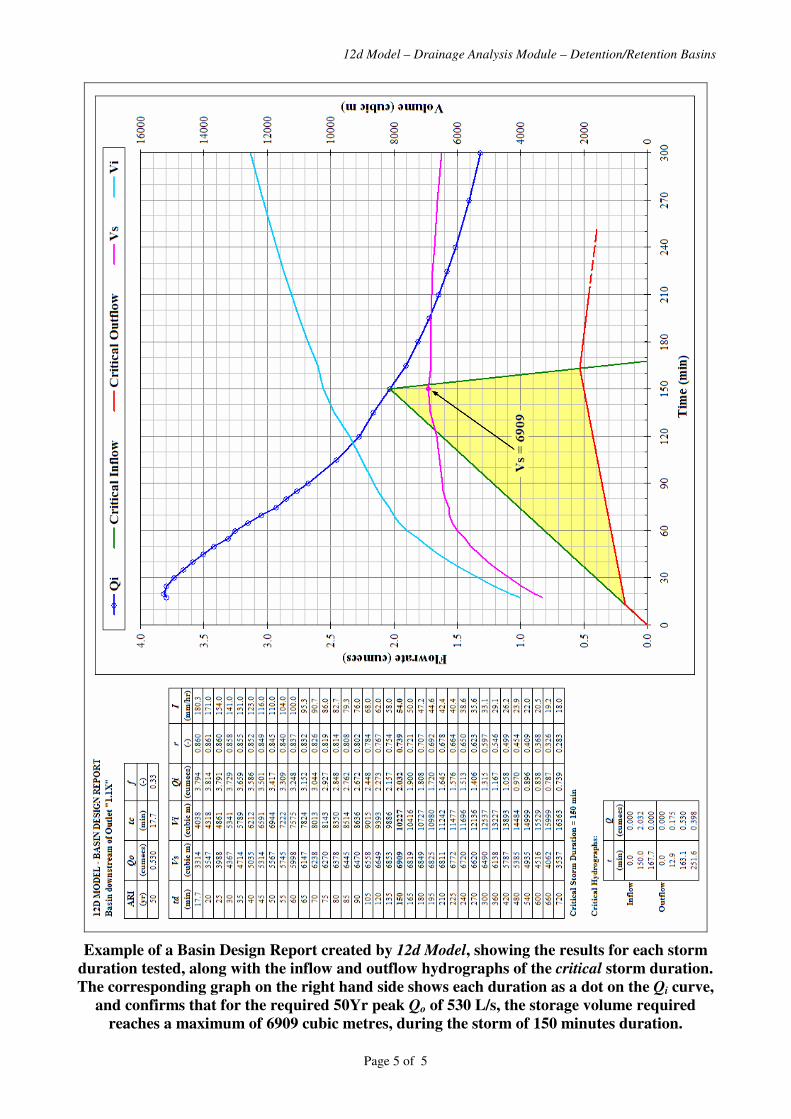
12d Model – Drainage Analysis Module – Detention/Retention Basins
Page 5 of 5
Example of a Basin Design Report created by 12d Model, showing the results for each storm
duration tested, along with the inflow and outflow hydrographs of the critical storm duration.
The corresponding graph on the right hand side shows each duration as a dot on the Qi curve,
and confirms that for the required 50Yr peak Qo of 530 L/s, the storage volume required
reaches a maximum of 6909 cubic metres, during the storm of 150 minutes duration.

Page 1 of 11
12d Model Civil and Surveying Software
Version 8
Drainage Analysis Module
Hydraulics
Owen Thornton BE (Mech), 12d Model Programmer
04 June 2007
Revised:
23 August 2007 (V8C1i)
04 February 2008 (V8C1p)
This document defines the various terms relevant to the hydraulic calculations performed by the
Drainage Analysis module of 12d Model version 8, including how and where they are calculated.
The terms pipe and channel are sometimes used interchangeably, as are the terms pit, manhole, inlet
and structure.

12d Model – V8 Drainage Analysis Module – Hydraulics
Page 2 of 11
Definitions:
Qrat = Peak Flow The peak flow rate for the pipe, without consideration of bypass flows. It is determined from the
contributing catchments via the Rational Method (and includes any direct pit or pipe flow that may
have been specified upstream). It is shown in the Hydraulic Report as "Peak Flow Qrat", and is also
set as a pipe attribute named "calculated peak flow".
Qb = Net Bypass Flow When considering bypass flows, Qb for the pipe is determined from an analysis of all the upstream
pits contributing to the pipe, as recommended in the Australian Rainfall and Runoff. It represents
the sum of the peak bypass flows approaching these pits, minus the sum of the peak bypass flows
leaving them. It is shown in the Hydraulic Report as "Net Bypass Flow Qb", and is also set as a pipe
attribute named "calculated net bypass flow". Note: the peak bypass flow leaving each pit, is
determined from the pit inlet capacity data, defined for each pit type in the drainage.4d setup file, as
well as the relevant choke factor determined for each pit.
Q = Pipe Flow = Qrat + Qb The peak flow rate in the pipe, represented by the sum of Qrat and Qb. It is shown in the Hydraulic
Report as "Pipe Flow Q", and is also set as a pipe attribute named "pipe flow". Note: it is only when
considering bypass flows, that Q may differ from Qrat.
Qx = Excess Pipe Flow If the pipe flow, Q, is so large that the HGL would rise above the upstream pit’s grate level, then Qx
will represent the difference between Q and the flow rate that would keep the HGL just at the grate
level. It is shown in the Hydraulic Report as "Excess Pipe Flow Qx", and is also set as a pipe
attribute named "calculated excess flow". Note: the excess flow amount, Qx, is still included in the
pipe flow, Q, and is not automatically re-routed to the overland system. However, when considering
bypass flows, the user may set the Qx routing increment to a value greater than zero, which will
initiate extra analysis passes to re-route just enough flow as is necessary, from the pipe network to
the overland system, so as to eradicate the excess pipe flows. At each extra pass, an amount no
greater than the Qx routing increment is removed from the pipe network – from the most upstream
pipe(s) with excess flow(s) – and re-routed to the overland system. If flow is entering from the top
of a pipe’s upstream pit, the re-routing is achieved initially by reducing the pit’s choke factor by an
amount calculated to have the same effect. Once the choke factor is reduced to zero, however, any
remaining Qx is re-routed as pit surcharge flow, Qs.
Qs = Pit Surcharge Flow When (and only when) excess pipe flows are re-routed to the overland system, it possible for some
pits to surcharge (flow rising up and exiting the top of the pit). At such pits, the choke factor will
have been reduced to zero, and Qs will have a positive value equal in magnitude to the negative pit
inflow. In the Hydrology Report, a negative value of "Inlet Flow Qi" indicates a surcharge flow,
and Qs is also set as a pit attribute named "calculated surcharge flow". Note: pit surcharge flow is
automatically included in the bypass flow leaving a pit, and may re-enter the pipe network
elsewhere.
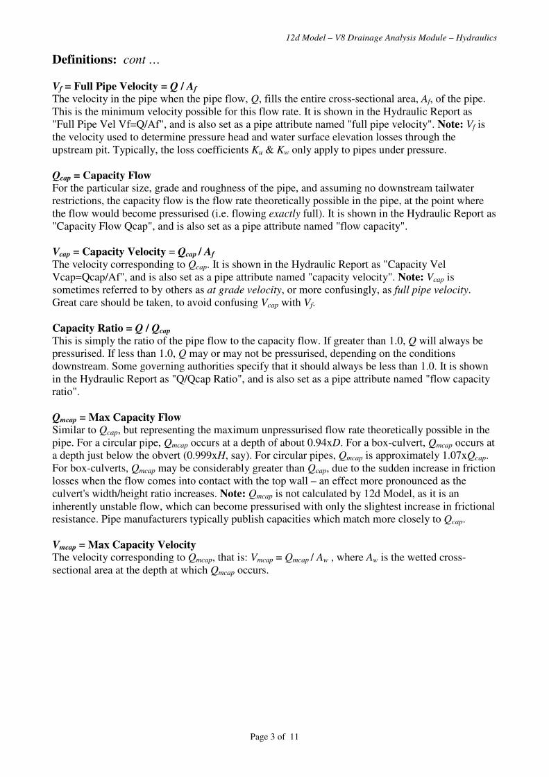
12d Model – V8 Drainage Analysis Module – Hydraulics
Page 3 of 11
Definitions: cont …
Vf = Full Pipe Velocity = Q / Af The velocity in the pipe when the pipe flow, Q, fills the entire cross-sectional area, Af, of the pipe.
This is the minimum velocity possible for this flow rate. It is shown in the Hydraulic Report as
"Full Pipe Vel Vf=Q/Af", and is also set as a pipe attribute named "full pipe velocity". Note: Vf is
the velocity used to determine pressure head and water surface elevation losses through the
upstream pit. Typically, the loss coefficients Ku & Kw only apply to pipes under pressure.
Qcap = Capacity Flow For the particular size, grade and roughness of the pipe, and assuming no downstream tailwater
restrictions, the capacity flow is the flow rate theoretically possible in the pipe, at the point where
the flow would become pressurised (i.e. flowing exactly full). It is shown in the Hydraulic Report as
"Capacity Flow Qcap", and is also set as a pipe attribute named "flow capacity".
Vcap = Capacity Velocity = Qcap / Af
The velocity corresponding to Qcap. It is shown in the Hydraulic Report as "Capacity Vel
Vcap=Qcap/Af", and is also set as a pipe attribute named "capacity velocity". Note: Vcap is
sometimes referred to by others as at grade velocity, or more confusingly, as full pipe velocity.
Great care should be taken, to avoid confusing Vcap with Vf.
Capacity Ratio = Q / Qcap This is simply the ratio of the pipe flow to the capacity flow. If greater than 1.0, Q will always be
pressurised. If less than 1.0, Q may or may not be pressurised, depending on the conditions
downstream. Some governing authorities specify that it should always be less than 1.0. It is shown
in the Hydraulic Report as "Q/Qcap Ratio", and is also set as a pipe attribute named "flow capacity
ratio".
Qmcap = Max Capacity Flow Similar to Qcap, but representing the maximum unpressurised flow rate theoretically possible in the
pipe. For a circular pipe, Qmcap occurs at a depth of about 0.94xD. For a box-culvert, Qmcap occurs at
a depth just below the obvert (0.999xH, say). For circular pipes, Qmcap is approximately 1.07xQcap.
For box-culverts, Qmcap may be considerably greater than Qcap, due to the sudden increase in friction
losses when the flow comes into contact with the top wall – an effect more pronounced as the
culvert's width/height ratio increases. Note: Qmcap is not calculated by 12d Model, as it is an
inherently unstable flow, which can become pressurised with only the slightest increase in frictional
resistance. Pipe manufacturers typically publish capacities which match more closely to Qcap.
Vmcap = Max Capacity Velocity The velocity corresponding to Qmcap, that is: Vmcap = Qmcap / Aw , where Aw is the wetted cross-
sectional area at the depth at which Qmcap occurs.

12d Model – V8 Drainage Analysis Module – Hydraulics
Page 4 of 11
Definitions: cont …
dn = Normal Depth The depth in the pipe when the slope of the water surface of the pipe flow, Q, is parallel to the pipe
slope. If Q is greater than Qcap, dn is set to the obvert of the pipe. It is set as a pipe attribute named
"normal depth", and the value [dn / <pipe height>] is set as "normal depth relative".
dc = Critical Depth The depth in the pipe when the local energy head (the sum of the pressure and velocity heads only,
ignoring the gravity head) of the pipe flow, Q, is at a minimum. It is set as a pipe attribute named
"critical depth", and the value [dc / <pipe height>] is set as "critical depth relative".
Vn = Normal Depth Velocity The velocity in the pipe when the pipe flow, Q, is flowing at the normal depth, dn. This is the
maximum velocity possible for this flow rate, in the most common case of a "steep" slope pipe
(where dc > dn). In the rare case of a "mild" slope pipe (where dc < dn), it is possible for the velocity
to be slightly greater near the downstream end of the pipe, if the flow "drops off the end" and the
depth approaches dc. It is shown in the Hydraulic Report as "Norm Depth Vel Vn=Q/An", and is
also set as a pipe attribute named "normal velocity".
Vc = Critical Depth Velocity The velocity in the pipe when the pipe flow, Q, is flowing at the critical depth, dc. When the flow is
slower than Vc (deeper than dc) it is termed tranquil flow. When the flow is faster than Vc (shallower
than dc), it is termed rapid flow. It is shown in the Hydraulic Report as "Crit Depth Vel Vc=Q/Ac",
and is also set as a pipe attribute named "critical velocity".
Vmin & Vmax = Allowable Velocity Ranges for Vn and Vcap These velocity limits are often specified by governing authorities, to ensure that all pipe flows are
fast enough to wash away impediments, but not so fast as to scour the pipes. If set on the
GLOBAL=>Main tab of the Drainage Network Editor, they are checked against the calculated Vn
and/or Vcap values. If ever a calculated velocity is too low or too high, a new pipe grade is
recommended in the Output Window, to help remedy the problem.
Va = Actual Velocity (VicRoads manual) The Victorian "VicRoads" manual refers to a chart for determining the so-called actual velocity, Va,
in part-full pipes. The chart shows a relationship between Q / Qcap values and Va / Vcap values. The
resultant Va values from this chart, are equivalent to the normal depth velocity, Vn, values calculated
by 12d Model.
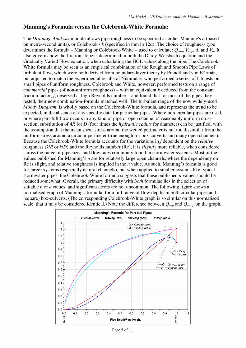
12d Model – V8 Drainage Analysis Module – Hydraulics
Page 5 of 11
Manning's Formula versus the Colebrook-White Formula:
The Drainage Analysis module allows pipe roughness to be specified as either Manning's n (based
on metre-second units), or Colebrook's k (specified in mm in 12d). The choice of roughness type
determines the formula – Manning or Colebrook-White – used to calculate: Qcap, Vcap, dn and Vn. It
also governs how the friction slope is determined in both the Darcy-Weisbach equation and the
Gradually Varied Flow equation, when calculating the HGL values along the pipe. The Colebrook-
White formula may be seen as an empirical combination of the Rough and Smooth Pipe Laws of
turbulent flow, which were both derived from boundary-layer theory by Prandtl and von Kármán,
but adjusted to match the experimental results of Nikuradse, who performed a series of lab tests on
small pipes of uniform roughness. Colebrook and White, however, performed tests on a range of
commercial pipes (of non-uniform roughness) – with an equivalent k deduced from the constant
friction factor, f, observed at high Reynolds number – and found that for most of the pipes they
tested, their new combination-formula matched well. The turbulent range of the now widely-used
Moody Diagram, is wholly based on the Colebrook-White formula, and represents the trend to be
expected, in the absence of any specific data for particular pipes. Where non-circular pipes are used,
or where part-full flow occurs in any kind of pipe or open channel of reasonably uniform cross-
section, substitution of 4R for D (four times the hydraulic radius for diameter) can be justified, with
the assumption that the mean shear-stress around the wetted perimeter is not too dissimilar from the
uniform stress around a circular perimeter (true enough for box-culverts and many open channels).
Because the Colebrook-White formula accounts for the variations in f dependent on the relative
roughness (k/R or k/D) and the Reynolds number (Re), it is slightly more reliable, when considered
across the range of pipe sizes and flow rates commonly found in stormwater systems. Most of the
values published for Manning’s n are for relatively large open channels, where the dependency on
Re is slight, and relative roughness is implied in the n value. As such, Manning’s formula is good
for larger systems (especially natural channels), but when applied to smaller systems like typical
stormwater pipes, the Colebrook-White formula suggests that these published n values should be
reduced somewhat. Overall, the primary difficulty with both formulae lies in the selection of
suitable n or k values, and significant errors are not uncommon. The following figure shows a
normalised graph of Manning's formula, for a full range of flow depths in both circular pipes and
(square) box-culverts. (The corresponding Colebrook-White graph is so similar on this normalised
scale, that it may be considered identical.) Note the difference between Qcap and Qmcap on the graph.

12d Model – V8 Drainage Analysis Module – Hydraulics
Page 6 of 11
The Hydraulic Grade Line (HGL):
In 12d Model, when a Drainage string is profiled or plotted, you have the option to display the HGL
determined from a storm analysis of the drainage network. The HGL represents the peak sum of the
pressure and gravity heads throughout the network, and in 12d, it is idealised to show separate head
losses along the pipes and through the pits. In reality, these losses are not separate, but continuous,
with the often highly un-developed flow near the pits, progressively forming fully-developed, one-
dimensional flow, in the pipe reaches sufficiently distant from the pits.
HGL Along Pipes: The HGL drawn along a pipe in 12d, is simply the straight line joining the
pipe’s idealised entrance and exit HGL levels. As such, in pipes where the steady flow is wholly
pressurised, it is a good representation of the friction slope, and consequent loss of total head (∆HT)
due to friction. However, where part-full flow occurs in any portion of the pipe, neither the friction
slope nor the water surface slope is constant, and so the straight line implies nothing other than the
idealised entrance and exit HGL levels. For these cases, the idealised HGL is calculated internally,
assuming fully-developed flow, via numerical integration of the Gradually Varied Flow equation.
This handles all possible cases of tranquil and rapid flow on mild and steep slope pipes, including
the hydraulic jumps that can occur on steep slopes. Note that, due to the non-uniform velocity head
in these cases, ∆HT due to friction cannot be determined from the idealised HGL, and must instead
be determined from the Total Energy Line (TEL).
HGL At Pits: The horizontal HGL drawn across a pit, represents the peak water surface elevation
(WSE) in that pit, and is tested against the freeboard and surcharge limits imposed there. The jump
in the HGL between a pit’s entrance and exit, represents the change (normally a loss) in pressure
head (∆HP) through that pit (it does not represent the loss in total head). If a pit’s entrance HGL
level is higher than the level formed by the minimum of dn and dc in an upstream pipe, then this
HGL level also forms a tailwater condition for that upstream pipe. Note that ∆WSE is typically
equal to, or slightly greater than ∆HP, and that both these jumps may, to a certain extent, be thought
of as the effect that a pit has on what would otherwise be fully-developed, one-dimensional flow.
Schematic of a typical HGL in a steep slope pipe
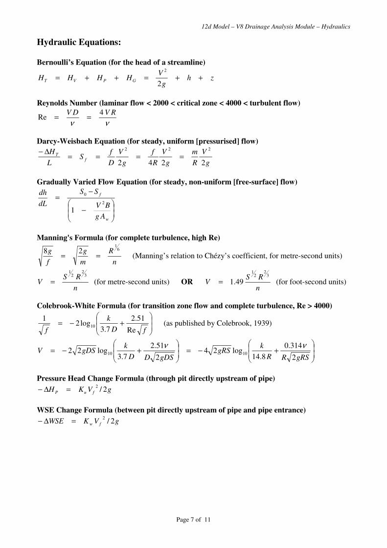
12d Model – V8 Drainage Analysis Module – Hydraulics
Page 7 of 11
Hydraulic Equations:
Bernoulli’s Equation (for the head of a streamline)
zhg
VHHHH GPVT ++=++=
2
2
Reynolds Number (laminar flow < 2000 < critical zone < 4000 < turbulent flow)
νν
RVDV 4Re ==
Darcy-Weisbach Equation (for steady, uniform [pressurised] flow)
g
V
R
m
g
V
R
f
g
V
D
fS
L
Hf
T
2242
222
====∆−
Gradually Varied Flow Equation (for steady, non-uniform [free-surface] flow)
��
�
�
��
�
�−
−=
w
f
Ag
BV
SS
dL
dh
2
0
1
Manning's Formula (for complete turbulence, high Re)
n
R
m
g
f
g 61
28== (Manning’s relation to Chézy’s coefficient, for metre-second units)
n
RSV
32
21
= (for metre-second units) OR n
RSV
32
21
49.1= (for foot-second units)
Colebrook-White Formula (for transition zone flow and complete turbulence, Re > 4000)
��
�
�
��
�
�+−=
fD
k
f Re
51.2
7.3log2
110 (as published by Colebrook, 1939)
��
�
�
��
�
�+−=
��
�
�
��
�
�+−=
gRSRR
kgRS
gDSDD
kgDSV
2
314.0
8.14log24
2
51.2
7.3log22 1010
νν
Pressure Head Change Formula (through pit directly upstream of pipe)
gVKH fuP 2/2
=∆−
WSE Change Formula (between pit directly upstream of pipe and pipe entrance)
gVKWSE fw 2/2
=∆−
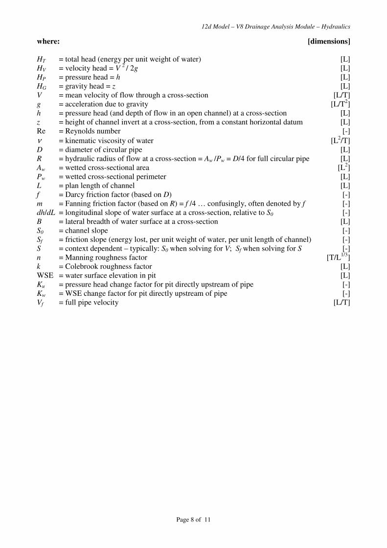
12d Model – V8 Drainage Analysis Module – Hydraulics
Page 8 of 11
where: [dimensions]
HT = total head (energy per unit weight of water) [L]
HV = velocity head = V 2
/ 2g [L]
HP = pressure head = h [L]
HG = gravity head = z [L]
V = mean velocity of flow through a cross-section [L/T]
g = acceleration due to gravity [L/T2]
h = pressure head (and depth of flow in an open channel) at a cross-section [L]
z = height of channel invert at a cross-section, from a constant horizontal datum [L]
Re = Reynolds number [-]
ν = kinematic viscosity of water [L2/T]
D = diameter of circular pipe [L]
R = hydraulic radius of flow at a cross-section = Aw /Pw = D/4 for full circular pipe [L]
Aw = wetted cross-sectional area [L2]
Pw = wetted cross-sectional perimeter [L]
L = plan length of channel [L]
f = Darcy friction factor (based on D) [-]
m = Fanning friction factor (based on R) = f /4 … confusingly, often denoted by f [-]
dh/dL = longitudinal slope of water surface at a cross-section, relative to S0 [-]
B = lateral breadth of water surface at a cross-section [L]
S0 = channel slope [-]
Sf = friction slope (energy lost, per unit weight of water, per unit length of channel) [-]
S = context dependent – typically: S0 when solving for V; Sf when solving for S [-]
n = Manning roughness factor [T/L1/3
]
k = Colebrook roughness factor [L]
WSE = water surface elevation in pit [L]
Ku = pressure head change factor for pit directly upstream of pipe [-]
Kw = WSE change factor for pit directly upstream of pipe [-]
Vf = full pipe velocity [L/T]
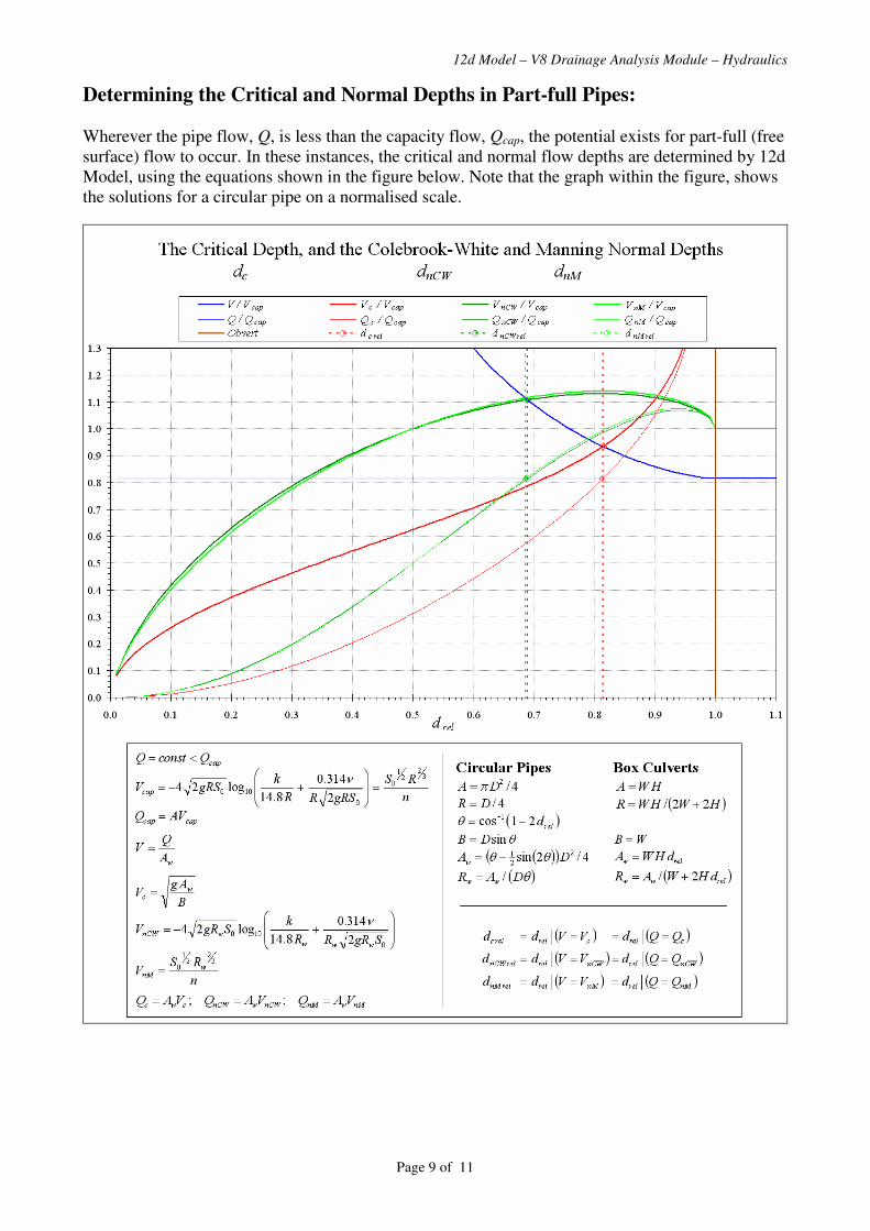
12d Model – V8 Drainage Analysis Module – Hydraulics
Page 9 of 11
Determining the Critical and Normal Depths in Part-full Pipes:
Wherever the pipe flow, Q, is less than the capacity flow, Qcap, the potential exists for part-full (free
surface) flow to occur. In these instances, the critical and normal flow depths are determined by 12d
Model, using the equations shown in the figure below. Note that the graph within the figure, shows
the solutions for a circular pipe on a normalised scale.
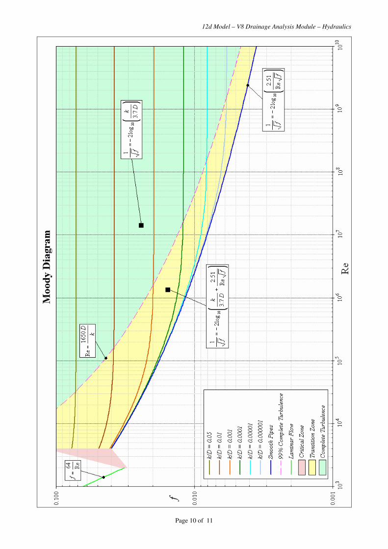
12d Model – V8 Drainage Analysis Module – Hydraulics
Page 10 of 11
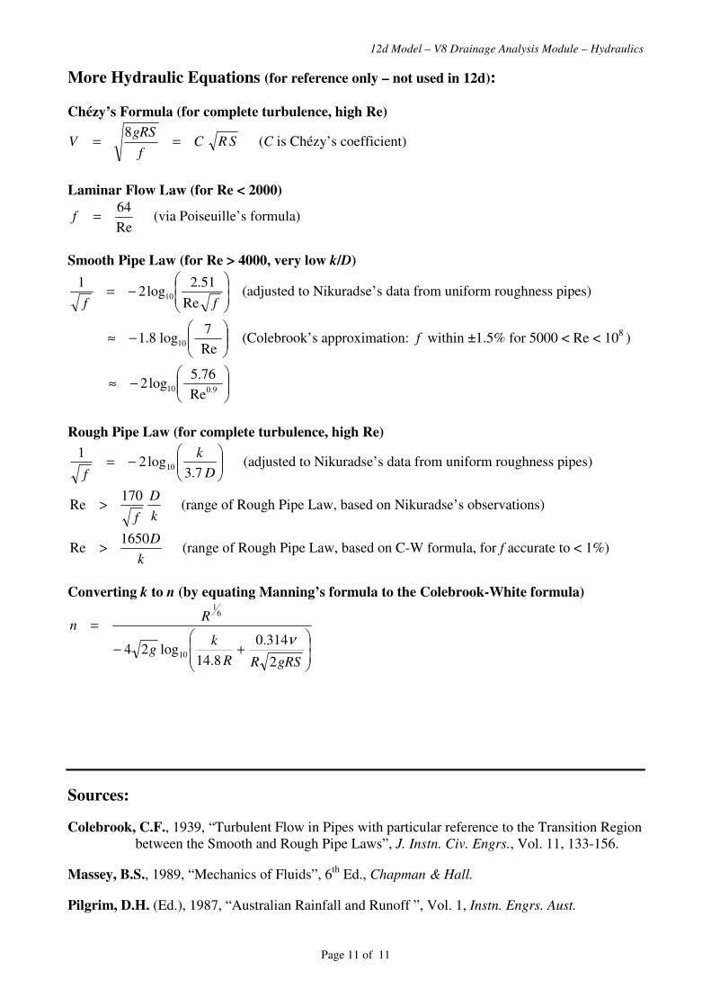
12d Model – V8 Drainage Analysis Module – Hydraulics
Page 11 of 11
More Hydraulic Equations (for reference only – not used in 12d):
Chézy’s Formula (for complete turbulence, high Re)
SRCf
gRSV ==
8 (C is Chézy’s coefficient)
Laminar Flow Law (for Re < 2000)
Re
64=f (via Poiseuille’s formula)
Smooth Pipe Law (for Re > 4000, very low k/D)
��
�
�
��
�
�−=
ff Re
51.2log2
110 (adjusted to Nikuradse’s data from uniform roughness pipes)
���
����
�−≈
Re
7log8.1 10 (Colebrook’s approximation: f within ±1.5% for 5000 < Re < 10
8 )
���
����
�−≈
9.010Re
76.5log2
Rough Pipe Law (for complete turbulence, high Re)
���
����
�−=
D
k
f 7.3log2
110 (adjusted to Nikuradse’s data from uniform roughness pipes)
k
D
f
170Re > (range of Rough Pipe Law, based on Nikuradse’s observations)
k
D1650Re > (range of Rough Pipe Law, based on C-W formula, for f accurate to < 1%)
Converting k to n (by equating Manning’s formula to the Colebrook-White formula)
��
�
�
��
�
�+−
=
gRSRR
kg
Rn
2
314.0
8.14log24 10
61
ν
Sources:
Colebrook, C.F., 1939, “Turbulent Flow in Pipes with particular reference to the Transition Region
between the Smooth and Rough Pipe Laws”, J. Instn. Civ. Engrs., Vol. 11, 133-156.
Massey, B.S., 1989, “Mechanics of Fluids”, 6th
Ed., Chapman & Hall.
Pilgrim, D.H. (Ed.), 1987, “Australian Rainfall and Runoff ”, Vol. 1, Instn. Engrs. Aust.

12d ModelCivil and Surveying Software
Version 8
Drainage Analysis Module
Ku & Kw Calculation
Owen Thornton BE (Mech), 12d Model Programmer
04 April 2006
Revised:
19 June 2007
10 September 2007
28 April 2008 (V8C1p)
This document describes the procedures for calculating
Ku and Kw coefficients, as implemented in the
Drainage Analysis module of 12d Model version 8.
For stormwater pits, maintenance holes and culvert inlets:
Ku coefficients apply to pressure head (Hp) losses.
For stormwater pits and maintenance holes:
Kw coefficients apply to water surface elevation (WSE) losses.
Page 1 of 21

12d Model - V8 Drainage Analysis Module - Ku & Kw
Introduction
For the design of piped stormwater systems, the loss (or gain) in pressure head (∆Hp) through a pit1, is typically assumed proportional to the velocity head at the entrance of the
downstream pipe. Likewise proportional, but sometimes of different magnitude, is the corresponding change in effective water surface elevation (∆WSE) between the pit and the
downstream pipe . However simple this may seem, the two coefficients of proportionality (denoted by Ku for pressure head changes, and Kw for WSE changes) are generally
dependent on so many different factors, that their adequate estimation still relies largely on the results of empirical study. Perhaps the most thorough sources emanating from such
study, are the so called "Missouri Charts" (Sangster et al , 1958) and "Hare Charts" (Hare, 1981). The Australian Rainfall and Runoff (ARR, 1987), suggests the use of these sets of
charts, in preference to any other method.
As originally published, the charts are highly complex, varied in presentation, and somewhat open to interpretation – reflective of the chaotic nature of flow through pits. A good
deal of judgement is required in selecting the appropriate chart to use for a particular pit configuration, and in most cases, iterative calculations are required. For large stormwater
networks, this typically leads to a huge time-cost for the designers, or alternatively, to an overly-conservative design approach. To overcome such problems, several semi-analytical
methods have been proposed, with an aim to replace the dependence on charts. These range from the relatively simple methods suggested by Argue (1986), Hare et al (1990)2, and
Mills et al (1998), to the more accurate methods (which are arguably as complex as using the charts manually) suggested by Parsell (1992), and Stein et al (1999). A summary
paper (O’Loughlin et al , 2002) reviewed the latter four of these methods, and concluded that none matched acceptably well, across the full range of pit configurations covered by
the charts, and that more work was required to develop a practical method suitable for implementation with a computer.
12d Model adopts a method that is purely numerical, rather than semi-analytical. It is based on the fact that the majority of the chart data (i.e. the charts for pits with no more than a
single upstream pipe) offer a range suitable for consideration in a continuous sense. This fact has allowed the chart data to be re-arranged and combined into a single database of Ku
and Kw values – one that both spreads evenly across the full range of the charts used, and is convenient for computation. The resultant database is used to calculate values which
match the charts perfectly , for those pits which coincide with one of the discrete chart configurations; otherwise, values are calculated which indicate a linear transition between
particular charts. The Ku and Kw calculations are all based on a robust, programmed sequence of one-dimensional and/or three-dimensional interpolations within the database.
The method may be thought of as a particular, holistic way of interpreting the chart data. It has been developed with an aim to minimise user input, and increase the overall
efficiency of the design process. Individual charts do not need to be nominated at each pit, and horizontal and vertical misalignment of pipes (a key factor affecting Ku and Kw) is
considered with minimal interaction. The method is most reliable for pits with either no upstream pipe, or one upstream pipe. For pits with two or more upstream pipes (for which
very few discrete charts exist) a single equivalent upstream pipe is determined, yielding results which compare adequately with the limited chart data available.
For culvert inlets, a different method is employed to calculate Ku values for culverts flowing under inlet control. In these cases, a Ku value must be specified directly for when the
culvert flows under outlet control. The resultant headwater depth attained with this direct value, is then compared with the headwater depth calculated from variants of the weir or
orifice flow formulae (modified to match published standard headwater nomographs for pipe and box culverts flowing under inlet control). If the latter headwater depth is greater,
the culvert is assumed to be flowing under inlet control, and a higher Ku value is back-calculated to account for the greater loss in pressure head through the headwall.
1 The term "pit" is extended in meaning here, to include maintenance holes (where no grate inlet flow from above is possible).
2 Sometimes referred to as the "Hare Equations". These equations differ from the "Hare Charts", in that they offer only an approximation to the preferred configuration charts
(see configurations: G1, T1, T2, T4, T8, T10).
Page 2 of 21
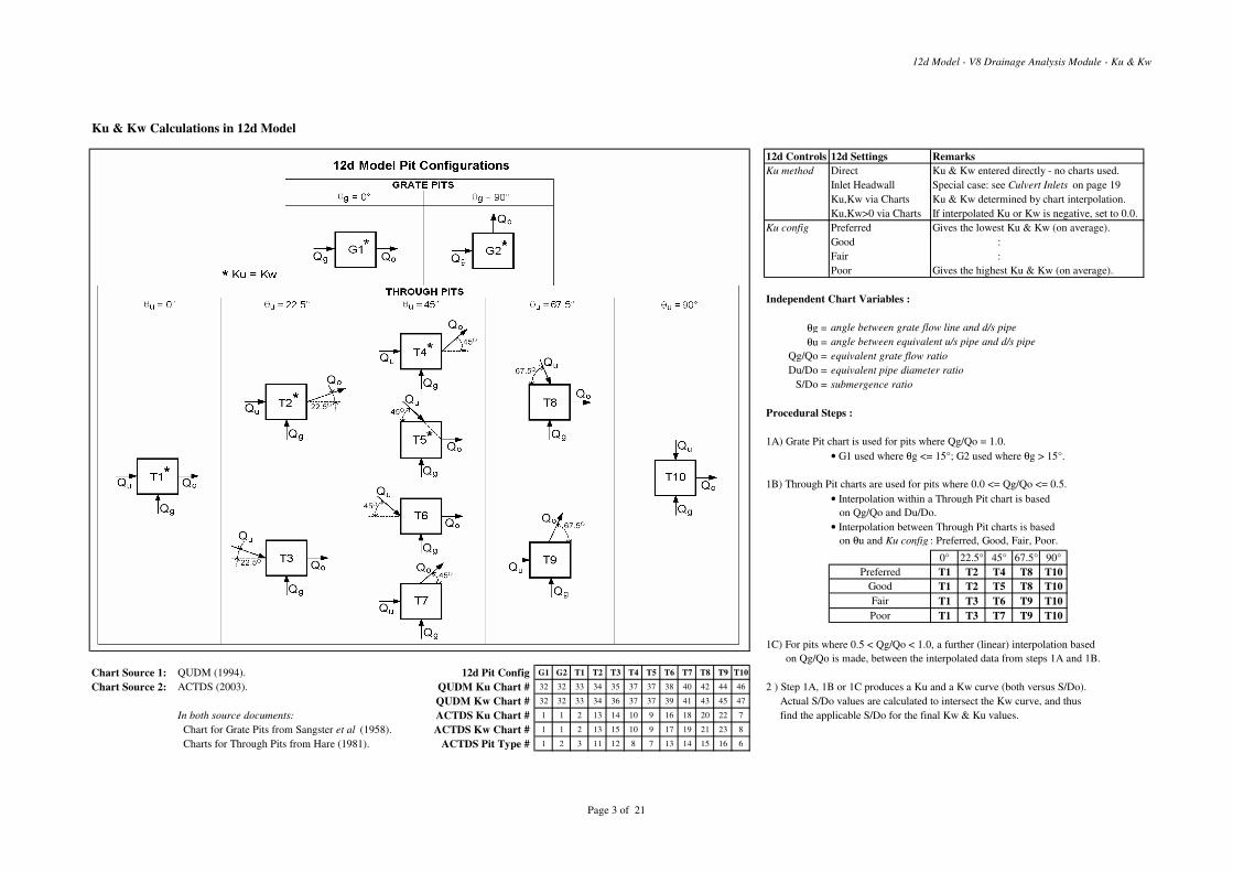
12d Model - V8 Drainage Analysis Module - Ku & Kw
Ku & Kw Calculations in 12d Model
12d Controls 12d Settings Remarks
Ku method Direct Ku & Kw entered directly - no charts used.
Inlet Headwall Special case: see Culvert Inlets on page 19
Ku,Kw via Charts Ku & Kw determined by chart interpolation.
Ku,Kw>0 via Charts If interpolated Ku or Kw is negative, set to 0.0.
Ku config Preferred Gives the lowest Ku & Kw (on average).
Good :
Fair :
Poor Gives the highest Ku & Kw (on average).
Independent Chart Variables :
θg = angle between grate flow line and d/s pipe
θu = angle between equivalent u/s pipe and d/s pipe
Qg/Qo = equivalent grate flow ratio
Du/Do = equivalent pipe diameter ratio
S/Do = submergence ratio
Procedural Steps :
1A) Grate Pit chart is used for pits where Qg/Qo = 1.0.
• G1 used where θg <= 15°; G2 used where θg > 15°.
1B) Through Pit charts are used for pits where 0.0 <= Qg/Qo <= 0.5.
• Interpolation within a Through Pit chart is based
on Qg/Qo and Du/Do.
• Interpolation between Through Pit charts is based
on θu and Ku config : Preferred, Good, Fair, Poor.
0° 22.5° 45° 67.5° 90°
Preferred T1 T2 T4 T8 T10
Good T1 T2 T5 T8 T10
Fair T1 T3 T6 T9 T10
Poor T1 T3 T7 T9 T10
1C) For pits where 0.5 < Qg/Qo < 1.0, a further (linear) interpolation based
on Qg/Qo is made, between the interpolated data from steps 1A and 1B.
Chart Source 1: QUDM (1994). 12d Pit Config G1 G2 T1 T2 T3 T4 T5 T6 T7 T8 T9 T10
Chart Source 2: ACTDS (2003). QUDM Ku Chart # 32 32 33 34 35 37 37 38 40 42 44 46 2 ) Step 1A, 1B or 1C produces a Ku and a Kw curve (both versus S/Do).
QUDM Kw Chart # 32 32 33 34 36 37 37 39 41 43 45 47 Actual S/Do values are calculated to intersect the Kw curve, and thus
In both source documents: ACTDS Ku Chart # 1 1 2 13 14 10 9 16 18 20 22 7 find the applicable S/Do for the final Kw & Ku values.
Chart for Grate Pits from Sangster et al (1958). ACTDS Kw Chart # 1 1 2 13 15 10 9 17 19 21 23 8
Charts for Through Pits from Hare (1981). ACTDS Pit Type # 1 2 3 11 12 8 7 13 14 15 16 6
Page 3 of 21
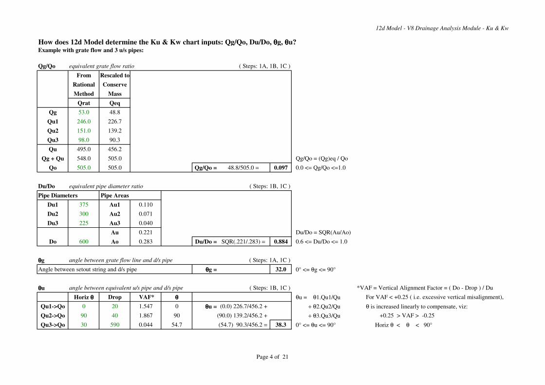
12d Model - V8 Drainage Analysis Module - Ku & Kw
How does 12d Model determine the Ku & Kw chart inputs: Qg/Qo, Du/Do, θθθθg, θθθθu?Example with grate flow and 3 u/s pipes:
Qg/Qo equivalent grate flow ratio ( Steps: 1A, 1B, 1C )
From Rescaled to
Rational Conserve
Method Mass
Qrat Qeq
Qg 53.0 48.8
Qu1 246.0 226.7
Qu2 151.0 139.2
Qu3 98.0 90.3
Qu 495.0 456.2
Qg + Qu 548.0 505.0 Qg/Qo = (Qg)eq / Qo
Qo 505.0 505.0 Qg/Qo = 48.8/505.0 = 0.097 0.0 <= Qg/Qo <=1.0
Du/Do equivalent pipe diameter ratio ( Steps: 1B, 1C )
Pipe Diameters Pipe Areas
Du1 375 Au1 0.110
Du2 300 Au2 0.071
Du3 225 Au3 0.040
Au 0.221 Du/Do = SQR(Au/Ao)
Do 600 Ao 0.283 Du/Do = SQR(.221/.283) = 0.884 0.6 <= Du/Do <= 1.0
θθθθg angle between grate flow line and d/s pipe ( Steps: 1A, 1C )
Angle between setout string and d/s pipe θθθθg = 32.0 0° <= θg <= 90°
θθθθu angle between equivalent u/s pipe and d/s pipe ( Steps: 1B, 1C ) *VAF = Vertical Alignment Factor = ( Do - Drop ) / Du
Horiz θθθθ Drop VAF* θθθθ θu = θ1.Qu1/Qu For VAF < +0.25 ( i.e. excessive vertical misalignment),
Qu1->Qo 0 20 1.547 0 θθθθu = (0.0) 226.7/456.2 + + θ2.Qu2/Qu θ is increased linearly to compensate, viz:
Qu2->Qo 90 40 1.867 90 (90.0) 139.2/456.2 + + θ3.Qu3/Qu +0.25 > VAF > -0.25
Qu3->Qo 30 590 0.044 54.7 (54.7) 90.3/456.2 = 38.3 0° <= θu <= 90° Horiz θ < θ < 90°
Page 4 of 21

12d Model - V8 Drainage Analysis Module - Ku & Kw
Grate Pits ( i.e. grate flow only)Example of Kw calculation (Ku = Kw) :
INPUT Chart : G1 G2 (G2)
θθθθg 32.0 θθθθg 0° 90° (>15°)
Do 0.300 S/Do Kw Kw Kw.Vo2/2g WSE S S/Do Error G1 used where θg <= 15°
Vo 0.920 1.5 7.00 9.70 0.419 28.319 1.095 3.650 -2.150 G2 used where θg > 15°
ILo 27.224 2.0 4.80 7.00 0.302 28.202 0.978 3.261 -1.261 (as per Chart 32 of QUDM, 1994)
HGLo 27.900 2.5 3.75 4.90 0.212 28.112 0.888 2.959 -0.459
3.0 3.15 3.80 0.164 28.064 0.840 2.800 0.200
4.0 2.45 2.72 0.117 28.017 0.793 2.645 1.355
5.0 2.10 2.20 0.095 27.995 0.771 2.570 2.430
6.0 1.90 1.98 0.086 27.986 0.762 2.538 3.462
7.0 1.80 1.87 0.081 27.981 0.757 2.523 4.477 −∆WSE = WSE - HGLo = Kw.Vo2/2g
WSE = Kw.Vo2/2g + HGLo
Answer: Kw = Ku = 4.05 … S/Do = 2.80
1
2
3
4
5
6
7
8
9
10
1.5 2.0 2.5 3.0 3.5 4.0 4.5 5.0 5.5 6.0 6.5 7.0S/Do
Kw
G1 Chart G2 Chart G2 Intersection
Page 5 of 21
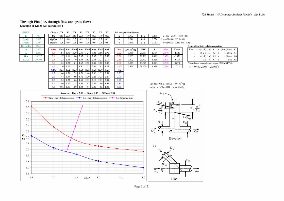
12d Model - V8 Drainage Analysis Module - Ku & Kw
Through Pits ( i.e. through flow and grate flow)Example of Ku & Kw calculation :
INPUT Chart : T3 T3 T3 T3 T7 T7 T7 T7 3-d interpolation factors
θθθθu 38.3 θθθθu 22.5 22.5 22.5 22.5 45.0 45.0 45.0 45.0 a 0.702 1 - a 0.298 a = (θu - 22.5) / (45.0 - 22.5)
Qg/Qo 0.097 Qg/Qo 0.0 0.0 0.5 0.5 0.0 0.0 0.5 0.5 b 0.246 1 - b 0.754 * b = (N - 0.0) / (0.5 - 0.0)
Du/Do 0.884 Du/Do 0.8 0.9 0.8 0.9 0.8 0.9 0.8 0.9 c 0.840 1 - c 0.160 c = (Du/Do - 0.8) / (0.9 - 0.8)
Ku config Poor General 3-d interpolation equation
Do 0.600 S/Do Kw1 Kw2 Kw3 Kw4 Kw5 Kw6 Kw7 Kw8 Kw Kw.Vo2/2g WSE S S/Do Error K = (1-a) (1-b) (1-c) K1 + (1-a) (1-b) c K2
Vo 2.340 1.5 1.84 1.98 2.30 2.35 3.24 3.01 2.86 2.90 2.72 0.761 29.861 1.584 2.640 -1.140 + (1-a) b (1-c) K3 + (1-a) b c K4
ILo 28.277 2.0 1.57 1.69 2.00 2.05 2.81 2.65 2.55 2.53 2.38 0.665 29.765 1.488 2.479 -0.479 + a (1-b) (1-c) K5 + a (1-b) c K6
HGLo 29.100 2.5 1.33 1.43 1.79 1.83 2.62 2.48 2.21 2.19 2.15 0.602 29.702 1.425 2.375 0.125 + a b (1-c) K7 + a b c K8
3.0 1.25 1.32 1.61 1.63 2.58 2.41 2.08 2.05 2.06 0.575 29.675 1.398 2.330 0.670 * Non-linear interpolation, as per QUDM (1994).
4.0 1.16 1.22 1.52 1.50 2.53 2.36 1.91 1.87 1.97 0.550 29.650 1.373 2.289 1.711 N = 0.66 (2.Qg/Qo - [Qg/Qo]2
)
S/Do Ku1 Ku2 Ku3 Ku4 Ku5 Ku6 Ku7 Ku8 Ku
1.5 1.60 1.71 1.79 1.79 2.40 2.40 2.55 2.59 2.23
2.0 1.44 1.53 1.69 1.72 2.20 2.21 2.23 2.29 2.03
2.5 1.25 1.32 1.66 1.61 2.13 2.18 2.13 2.09 1.92
3.0 1.09 1.12 1.57 1.54 2.07 2.09 1.99 1.97 1.81 −∆WSE = WSE - HGLo = Kw.Vo2/2g
4.0 0.96 1.00 1.50 1.44 1.97 2.00 1.82 1.81 1.70 −∆Hp = HGLu - HGLo = Ku.Vo2/2g
Answer: Kw = 2.19 … Ku = 1.95 … S/Do = 2.39
1.6
1.7
1.8
1.9
2.0
2.1
2.2
2.3
2.4
2.5
2.6
2.7
2.8
1.5 2.0 2.5 3.0 3.5 4.0S/Do
Ku
Kw
Kw Chart Interpolation Ku Chart Interpolation Kw Intersection
Page 6 of 21
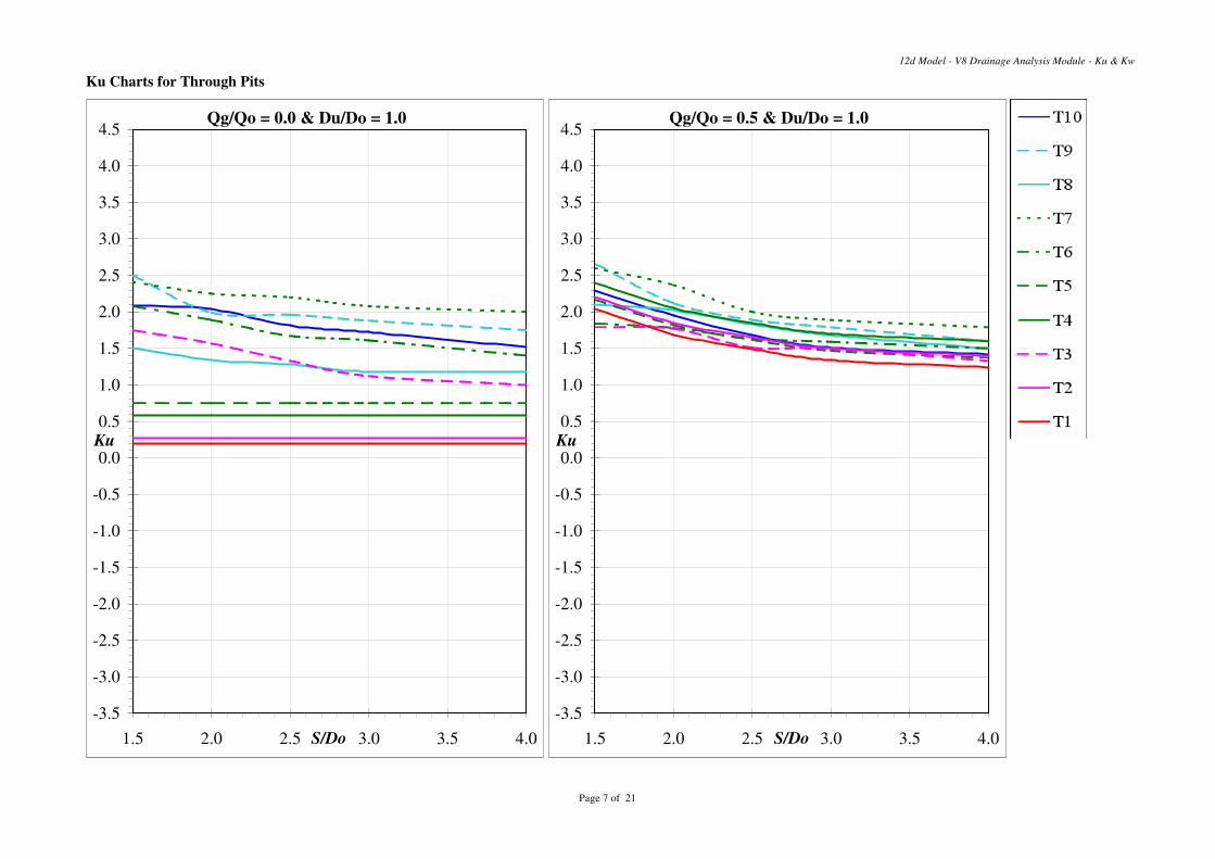
Ku Charts for Through Pits
12d Model - V8 Drainage Analysis Module - Ku & Kw
Qg/Qo = 0.0 & Du/Do = 1.0
-3.5
-3.0
-2.5
-2.0
-1.5
-1.0
-0.5
0.0
0.5
1.0
1.5
2.0
2.5
3.0
3.5
4.0
4.5
1.5 2.0 2.5 3.0 3.5 4.0S/Do
Ku
Qg/Qo = 0.5 & Du/Do = 1.0
-3.5
-3.0
-2.5
-2.0
-1.5
-1.0
-0.5
0.0
0.5
1.0
1.5
2.0
2.5
3.0
3.5
4.0
4.5
1.5 2.0 2.5 3.0 3.5 4.0S/Do
Ku
Page 7 of 21
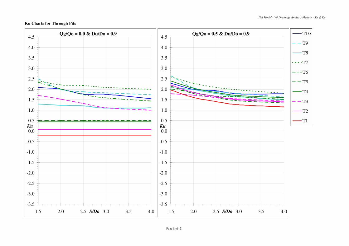
Ku Charts for Through Pits
12d Model - V8 Drainage Analysis Module - Ku & Kw
Qg/Qo = 0.0 & Du/Do = 0.9
-3.5
-3.0
-2.5
-2.0
-1.5
-1.0
-0.5
0.0
0.5
1.0
1.5
2.0
2.5
3.0
3.5
4.0
4.5
1.5 2.0 2.5 3.0 3.5 4.0S/Do
Ku
Qg/Qo = 0.5 & Du/Do = 0.9
-3.5
-3.0
-2.5
-2.0
-1.5
-1.0
-0.5
0.0
0.5
1.0
1.5
2.0
2.5
3.0
3.5
4.0
4.5
1.5 2.0 2.5 3.0 3.5 4.0S/Do
Ku
Page 8 of 21
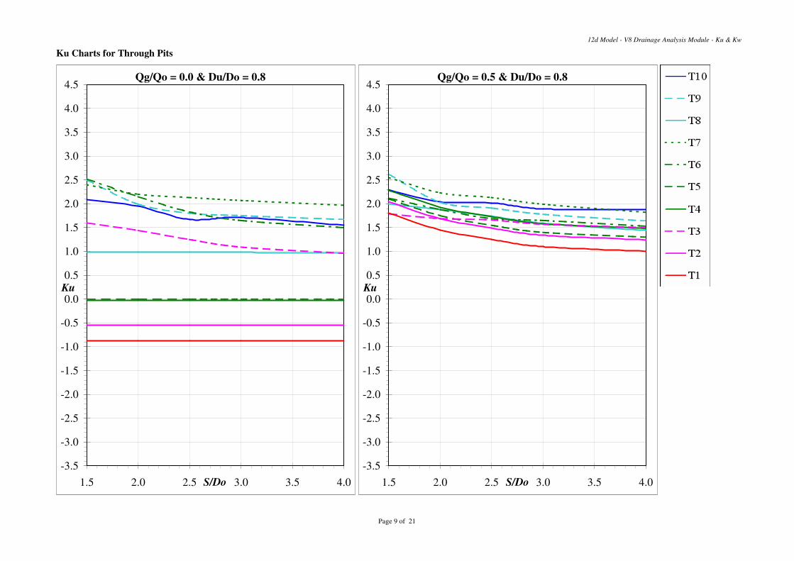
Ku Charts for Through Pits
12d Model - V8 Drainage Analysis Module - Ku & Kw
Qg/Qo = 0.0 & Du/Do = 0.8
-3.5
-3.0
-2.5
-2.0
-1.5
-1.0
-0.5
0.0
0.5
1.0
1.5
2.0
2.5
3.0
3.5
4.0
4.5
1.5 2.0 2.5 3.0 3.5 4.0S/Do
Ku
Qg/Qo = 0.5 & Du/Do = 0.8
-3.5
-3.0
-2.5
-2.0
-1.5
-1.0
-0.5
0.0
0.5
1.0
1.5
2.0
2.5
3.0
3.5
4.0
4.5
1.5 2.0 2.5 3.0 3.5 4.0S/Do
Ku
Page 9 of 21
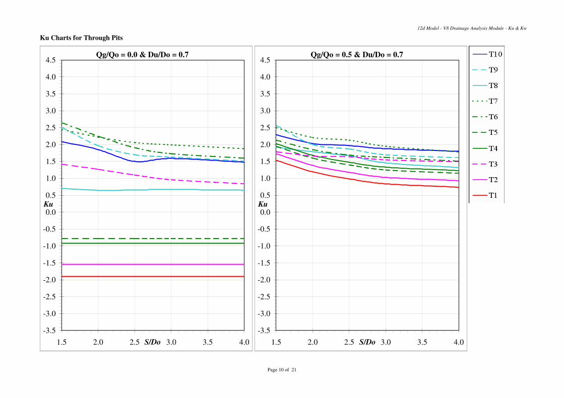
Ku Charts for Through Pits
12d Model - V8 Drainage Analysis Module - Ku & Kw
Qg/Qo = 0.0 & Du/Do = 0.7
-3.5
-3.0
-2.5
-2.0
-1.5
-1.0
-0.5
0.0
0.5
1.0
1.5
2.0
2.5
3.0
3.5
4.0
4.5
1.5 2.0 2.5 3.0 3.5 4.0S/Do
Ku
Qg/Qo = 0.5 & Du/Do = 0.7
-3.5
-3.0
-2.5
-2.0
-1.5
-1.0
-0.5
0.0
0.5
1.0
1.5
2.0
2.5
3.0
3.5
4.0
4.5
1.5 2.0 2.5 3.0 3.5 4.0S/Do
Ku
Page 10 of 21
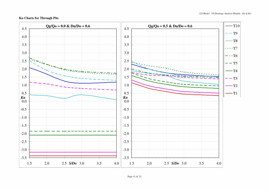
Ku Charts for Through Pits
12d Model - V8 Drainage Analysis Module - Ku & Kw
Qg/Qo = 0.0 & Du/Do = 0.6
-3.5
-3.0
-2.5
-2.0
-1.5
-1.0
-0.5
0.0
0.5
1.0
1.5
2.0
2.5
3.0
3.5
4.0
4.5
1.5 2.0 2.5 3.0 3.5 4.0S/Do
Ku
Qg/Qo = 0.5 & Du/Do = 0.6
-3.5
-3.0
-2.5
-2.0
-1.5
-1.0
-0.5
0.0
0.5
1.0
1.5
2.0
2.5
3.0
3.5
4.0
4.5
1.5 2.0 2.5 3.0 3.5 4.0S/Do
Ku
Page 11 of 21
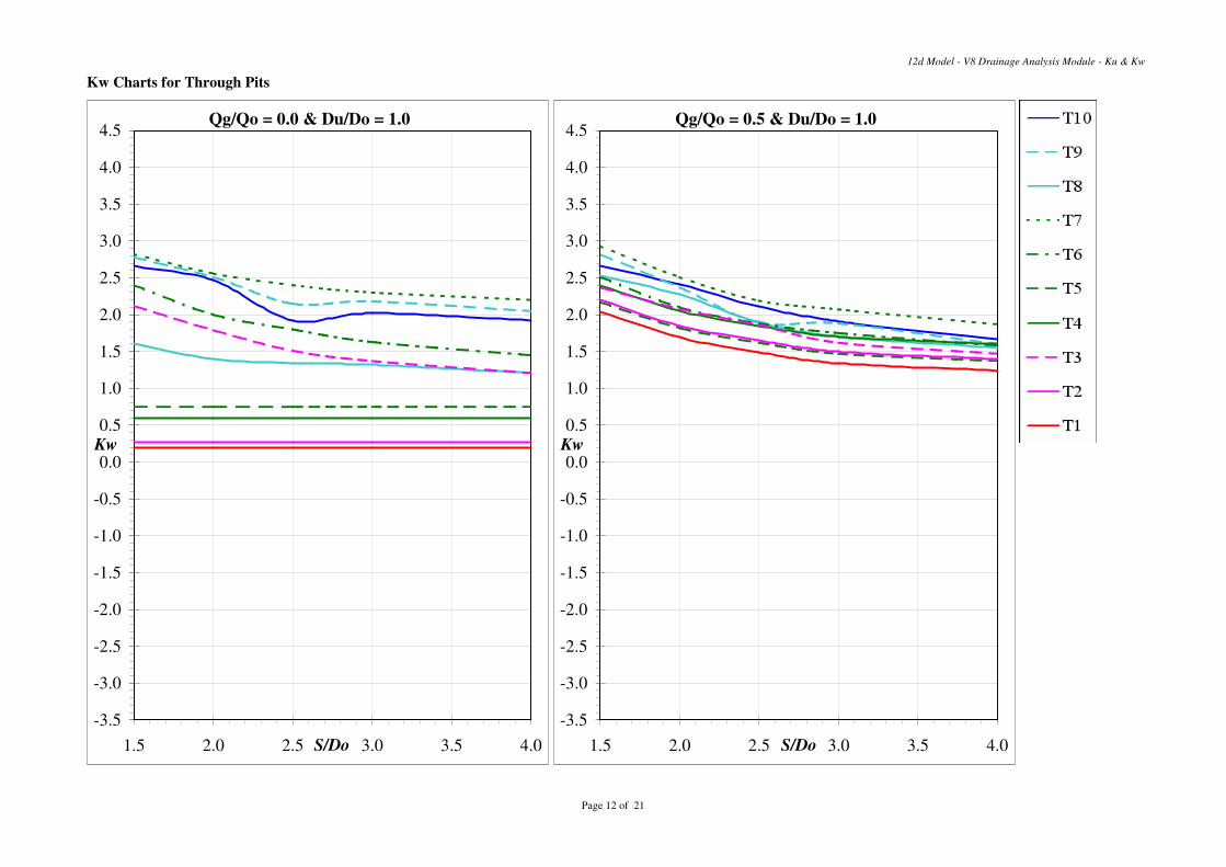
Kw Charts for Through Pits
12d Model - V8 Drainage Analysis Module - Ku & Kw
Qg/Qo = 0.0 & Du/Do = 1.0
-3.5
-3.0
-2.5
-2.0
-1.5
-1.0
-0.5
0.0
0.5
1.0
1.5
2.0
2.5
3.0
3.5
4.0
4.5
1.5 2.0 2.5 3.0 3.5 4.0S/Do
Kw
Qg/Qo = 0.5 & Du/Do = 1.0
-3.5
-3.0
-2.5
-2.0
-1.5
-1.0
-0.5
0.0
0.5
1.0
1.5
2.0
2.5
3.0
3.5
4.0
4.5
1.5 2.0 2.5 3.0 3.5 4.0S/Do
Kw
Page 12 of 21
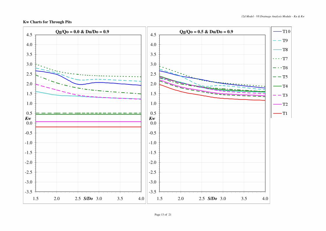
Kw Charts for Through Pits
12d Model - V8 Drainage Analysis Module - Ku & Kw
Qg/Qo = 0.0 & Du/Do = 0.9
-3.5
-3.0
-2.5
-2.0
-1.5
-1.0
-0.5
0.0
0.5
1.0
1.5
2.0
2.5
3.0
3.5
4.0
4.5
1.5 2.0 2.5 3.0 3.5 4.0S/Do
Kw
Qg/Qo = 0.5 & Du/Do = 0.9
-3.5
-3.0
-2.5
-2.0
-1.5
-1.0
-0.5
0.0
0.5
1.0
1.5
2.0
2.5
3.0
3.5
4.0
4.5
1.5 2.0 2.5 3.0 3.5 4.0S/Do
Kw
Page 13 of 21
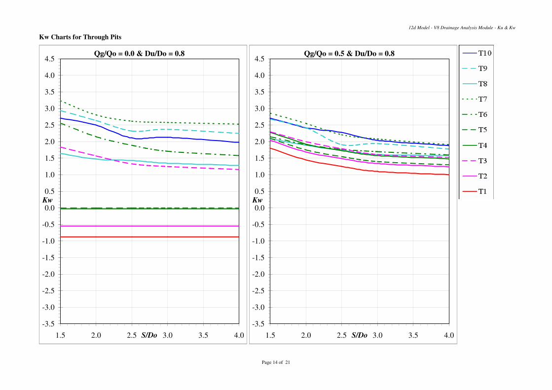
Kw Charts for Through Pits
12d Model - V8 Drainage Analysis Module - Ku & Kw
Qg/Qo = 0.0 & Du/Do = 0.8
-3.5
-3.0
-2.5
-2.0
-1.5
-1.0
-0.5
0.0
0.5
1.0
1.5
2.0
2.5
3.0
3.5
4.0
4.5
1.5 2.0 2.5 3.0 3.5 4.0S/Do
Kw
Qg/Qo = 0.5 & Du/Do = 0.8
-3.5
-3.0
-2.5
-2.0
-1.5
-1.0
-0.5
0.0
0.5
1.0
1.5
2.0
2.5
3.0
3.5
4.0
4.5
1.5 2.0 2.5 3.0 3.5 4.0S/Do
Kw
Page 14 of 21
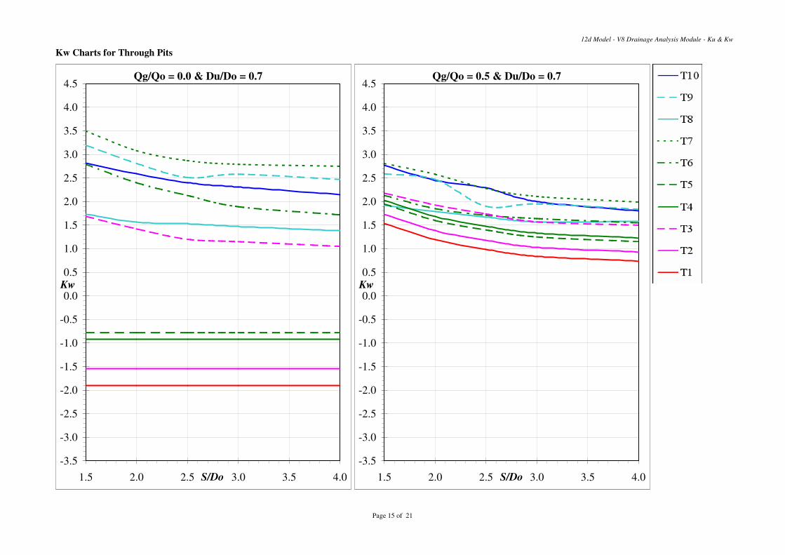
Kw Charts for Through Pits
12d Model - V8 Drainage Analysis Module - Ku & Kw
Qg/Qo = 0.0 & Du/Do = 0.7
-3.5
-3.0
-2.5
-2.0
-1.5
-1.0
-0.5
0.0
0.5
1.0
1.5
2.0
2.5
3.0
3.5
4.0
4.5
1.5 2.0 2.5 3.0 3.5 4.0S/Do
Kw
Qg/Qo = 0.5 & Du/Do = 0.7
-3.5
-3.0
-2.5
-2.0
-1.5
-1.0
-0.5
0.0
0.5
1.0
1.5
2.0
2.5
3.0
3.5
4.0
4.5
1.5 2.0 2.5 3.0 3.5 4.0S/Do
Kw
Page 15 of 21
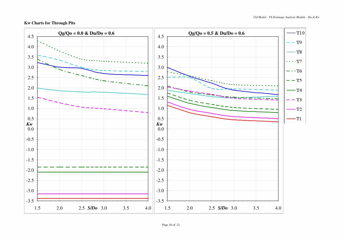
Kw Charts for Through Pits
12d Model - V8 Drainage Analysis Module - Ku & Kw
Qg/Qo = 0.0 & Du/Do = 0.6
-3.5
-3.0
-2.5
-2.0
-1.5
-1.0
-0.5
0.0
0.5
1.0
1.5
2.0
2.5
3.0
3.5
4.0
4.5
1.5 2.0 2.5 3.0 3.5 4.0S/Do
Kw
Qg/Qo = 0.5 & Du/Do = 0.6
-3.5
-3.0
-2.5
-2.0
-1.5
-1.0
-0.5
0.0
0.5
1.0
1.5
2.0
2.5
3.0
3.5
4.0
4.5
1.5 2.0 2.5 3.0 3.5 4.0S/Do
Kw
Page 16 of 21
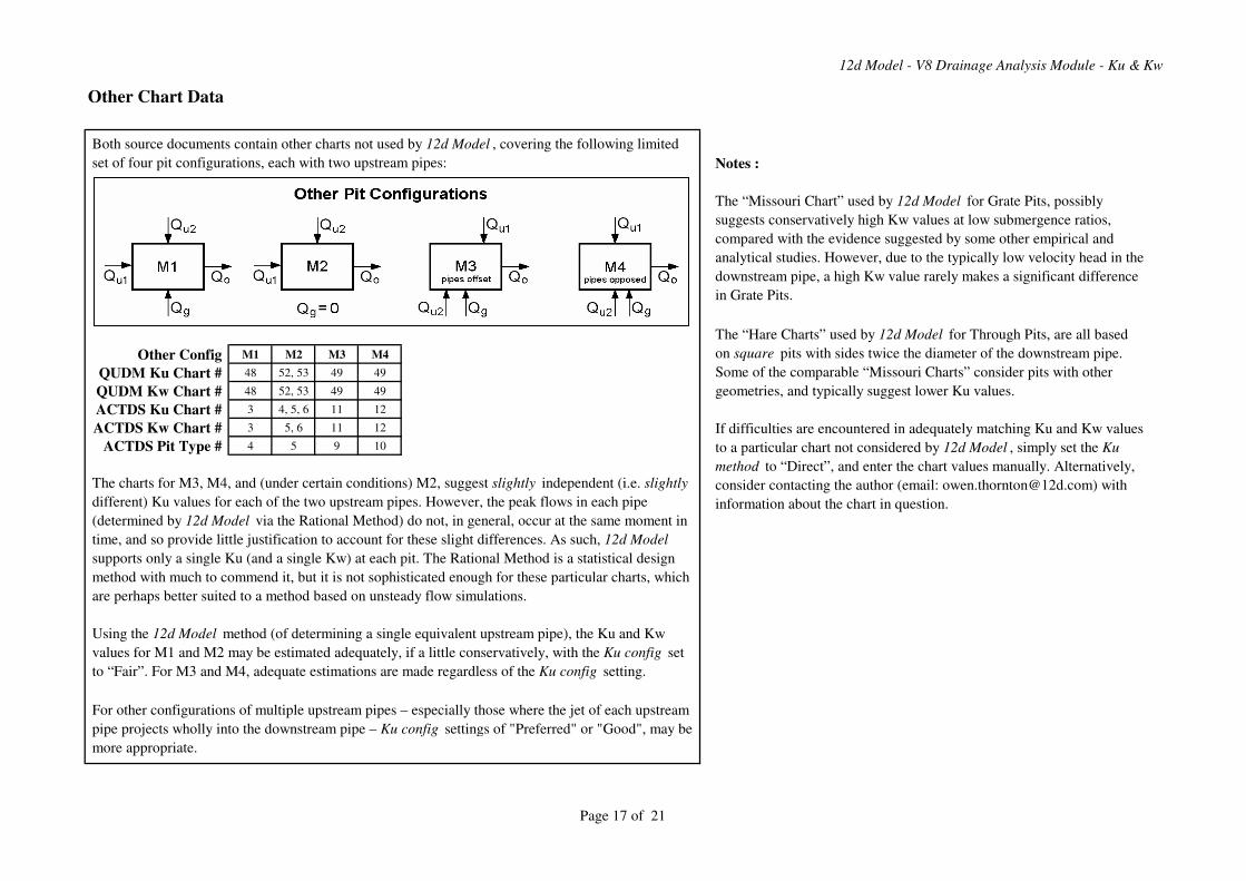
12d Model - V8 Drainage Analysis Module - Ku & Kw
Other Chart Data
Notes :
The “Missouri Chart” used by 12d Model for Grate Pits, possibly
suggests conservatively high Kw values at low submergence ratios,
compared with the evidence suggested by some other empirical and
analytical studies. However, due to the typically low velocity head in the
downstream pipe, a high Kw value rarely makes a significant difference
in Grate Pits.
Other Config M1 M2 M3 M4
QUDM Ku Chart # 48 52, 53 49 49
QUDM Kw Chart # 48 52, 53 49 49
ACTDS Ku Chart # 3 4, 5, 6 11 12
ACTDS Kw Chart # 3 5, 6 11 12
ACTDS Pit Type # 4 5 9 10
For other configurations of multiple upstream pipes – especially those where the jet of each upstream
pipe projects wholly into the downstream pipe – Ku config settings of "Preferred" or "Good", may be
more appropriate.
Both source documents contain other charts not used by 12d Model , covering the following limited
set of four pit configurations, each with two upstream pipes:
The “Hare Charts” used by 12d Model for Through Pits, are all based
on square pits with sides twice the diameter of the downstream pipe.
Some of the comparable “Missouri Charts” consider pits with other
geometries, and typically suggest lower Ku values.
If difficulties are encountered in adequately matching Ku and Kw values
to a particular chart not considered by 12d Model , simply set the Ku
method to “Direct”, and enter the chart values manually. Alternatively,
consider contacting the author (email: [email protected]) with
information about the chart in question.
The charts for M3, M4, and (under certain conditions) M2, suggest slightly independent (i.e. slightly
different) Ku values for each of the two upstream pipes. However, the peak flows in each pipe
(determined by 12d Model via the Rational Method) do not, in general, occur at the same moment in
time, and so provide little justification to account for these slight differences. As such, 12d Model
supports only a single Ku (and a single Kw) at each pit. The Rational Method is a statistical design
method with much to commend it, but it is not sophisticated enough for these particular charts, which
are perhaps better suited to a method based on unsteady flow simulations.
Using the 12d Model method (of determining a single equivalent upstream pipe), the Ku and Kw
values for M1 and M2 may be estimated adequately, if a little conservatively, with the Ku config set
to “Fair”. For M3 and M4, adequate estimations are made regardless of the Ku config setting.
Page 17 of 21
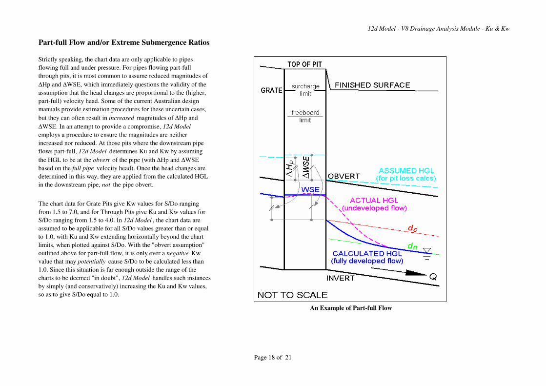
12d Model - V8 Drainage Analysis Module - Ku & Kw
Part-full Flow and/or Extreme Submergence Ratios
Strictly speaking, the chart data are only applicable to pipes
flowing full and under pressure. For pipes flowing part-full
through pits, it is most common to assume reduced magnitudes of
∆Hp and ∆WSE, which immediately questions the validity of the
assumption that the head changes are proportional to the (higher,
part-full) velocity head. Some of the current Australian design
manuals provide estimation procedures for these uncertain cases,
but they can often result in increased magnitudes of ∆Hp and
∆WSE. In an attempt to provide a compromise, 12d Model
employs a procedure to ensure the magnitudes are neither
increased nor reduced. At those pits where the downstream pipe
flows part-full, 12d Model determines Ku and Kw by assuming
the HGL to be at the obvert of the pipe (with ∆Hp and ∆WSE
based on the full pipe velocity head). Once the head changes are
determined in this way, they are applied from the calculated HGL
in the downstream pipe, not the pipe obvert.
The chart data for Grate Pits give Kw values for S/Do ranging
from 1.5 to 7.0, and for Through Pits give Ku and Kw values for
S/Do ranging from 1.5 to 4.0. In 12d Model , the chart data are
assumed to be applicable for all S/Do values greater than or equal
to 1.0, with Ku and Kw extending horizontally beyond the chart
limits, when plotted against S/Do. With the "obvert assumption"
outlined above for part-full flow, it is only ever a negative Kw
value that may potentially cause S/Do to be calculated less than
1.0. Since this situation is far enough outside the range of the
charts to be deemed "in doubt", 12d Model handles such instances
by simply (and conservatively) increasing the Ku and Kw values,
so as to give S/Do equal to 1.0.
An Example of Part-full Flow
Page 18 of 21
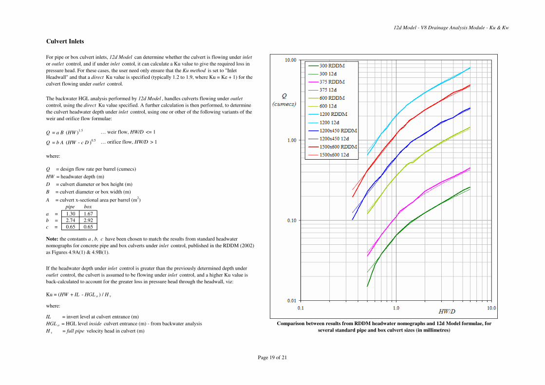
12d Model - V8 Drainage Analysis Module - Ku & Kw
Culvert Inlets
Q = a B (HW )1.5 … weir flow, HW/D <= 1
Q = b A (HW - c D )0.5 … orifice flow, HW/D > 1
where:
Q = design flow rate per barrel (cumecs)
HW = headwater depth (m)
D = culvert diameter or box height (m)
B = culvert diameter or box width (m)
A = culvert x-sectional area per barrel (m2)
pipe box
a = 1.30 1.67
b = 2.74 2.92
c = 0.65 0.65
Ku = (HW + IL - HGL o ) / H v
where:
IL = invert level at culvert entrance (m)
HGL o = HGL level inside culvert entrance (m) - from backwater analysis
H v = full pipe velocity head in culvert (m)
Comparison between results from RDDM headwater nomographs and 12d Model formulae, for
several standard pipe and box culvert sizes (in millimetres)
For pipe or box culvert inlets, 12d Model can determine whether the culvert is flowing under inlet
or outlet control, and if under inlet contol, it can calculate a Ku value to give the required loss in
pressure head. For these cases, the user need only ensure that the Ku method is set to "Inlet
Headwall" and that a direct Ku value is specified (typically 1.2 to 1.9, where Ku = Ke + 1) for the
culvert flowing under outlet control.
The backwater HGL analysis performed by 12d Model , handles culverts flowing under outlet
control, using the direct Ku value specified. A further calculation is then performed, to determine
the culvert headwater depth under inlet control, using one or other of the following variants of the
weir and orifice flow formulae:
Note: the constants a , b, c have been chosen to match the results from standard headwater
nomographs for concrete pipe and box culverts under inlet control, published in the RDDM (2002)
as Figures 4.9A(1) & 4.9B(1).
If the headwater depth under inlet control is greater than the previously determined depth under
outlet control, the culvert is assumed to be flowing under inlet control, and a higher Ku value is
back-calculated to account for the greater loss in pressure head through the headwall, viz:
Page 19 of 21
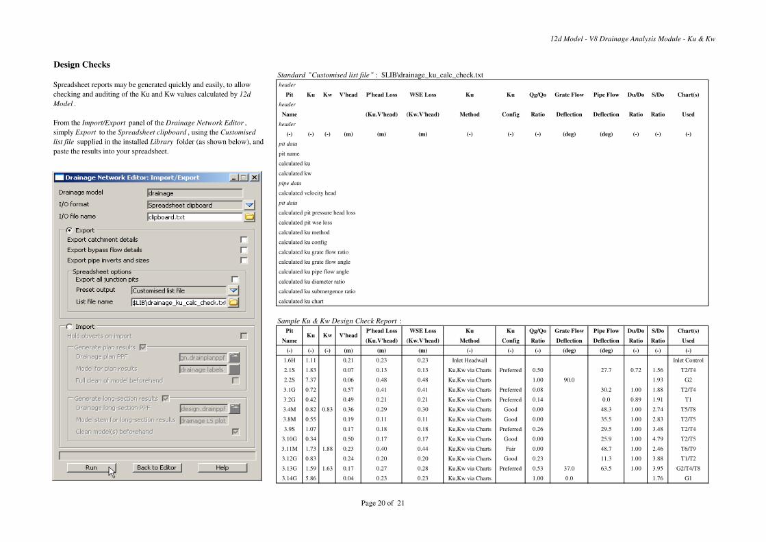
12d Model - V8 Drainage Analysis Module - Ku & Kw
Design ChecksStandard "Customised list file " : $LIB\drainage_ku_calc_check.txt
header
Pit Ku Kw V'head P'head Loss WSE Loss Ku Ku Qg/Qo Grate Flow Pipe Flow Du/Do S/Do Chart(s)
header
Name (Ku.V'head) (Kw.V'head) Method Config Ratio Deflection Deflection Ratio Ratio Used
header
(-) (-) (-) (m) (m) (m) (-) (-) (-) (deg) (deg) (-) (-) (-)
pit data
pit name
calculated ku
calculated kw
pipe data
calculated velocity head
pit data
calculated pit pressure head loss
calculated pit wse loss
calculated ku method
calculated ku config
calculated ku grate flow ratio
calculated ku grate flow angle
calculated ku pipe flow angle
calculated ku diameter ratio
calculated ku submergence ratio
calculated ku chart
Sample Ku & Kw Design Check Report :
Pit P'head Loss WSE Loss Ku Ku Qg/Qo Grate Flow Pipe Flow Du/Do S/Do Chart(s)
Name (Ku.V'head) (Kw.V'head) Method Config Ratio Deflection Deflection Ratio Ratio Used
(-) (-) (-) (m) (m) (m) (-) (-) (-) (deg) (deg) (-) (-) (-)
1.6H 1.11 0.21 0.23 0.23 Inlet Headwall Inlet Control
2.1S 1.83 0.07 0.13 0.13 Ku,Kw via Charts Preferred 0.50 27.7 0.72 1.56 T2/T4
2.2S 7.37 0.06 0.48 0.48 Ku,Kw via Charts 1.00 90.0 1.93 G2
3.1G 0.72 0.57 0.41 0.41 Ku,Kw via Charts Preferred 0.08 30.2 1.00 1.88 T2/T4
3.2G 0.42 0.49 0.21 0.21 Ku,Kw via Charts Preferred 0.14 0.0 0.89 1.91 T1
3.4M 0.82 0.83 0.36 0.29 0.30 Ku,Kw via Charts Good 0.00 48.3 1.00 2.74 T5/T8
3.8M 0.55 0.19 0.11 0.11 Ku,Kw via Charts Good 0.00 35.5 1.00 2.83 T2/T5
3.9S 1.07 0.17 0.18 0.18 Ku,Kw via Charts Preferred 0.26 29.5 1.00 3.48 T2/T4
3.10G 0.34 0.50 0.17 0.17 Ku,Kw via Charts Good 0.00 25.9 1.00 4.79 T2/T5
3.11M 1.73 1.88 0.23 0.40 0.44 Ku,Kw via Charts Fair 0.00 48.7 1.00 2.46 T6/T9
3.12G 0.83 0.24 0.20 0.20 Ku,Kw via Charts Good 0.23 11.3 1.00 3.88 T1/T2
3.13G 1.59 1.63 0.17 0.27 0.28 Ku,Kw via Charts Preferred 0.53 37.0 63.5 1.00 3.95 G2/T4/T8
3.14G 5.86 0.04 0.23 0.23 Ku,Kw via Charts 1.00 0.0 1.76 G1
Ku Kw
Spreadsheet reports may be generated quickly and easily, to allow
checking and auditing of the Ku and Kw values calculated by 12d
Model .
From the Import/Export panel of the Drainage Network Editor ,
simply Export to the Spreadsheet clipboard , using the Customised
list file supplied in the installed Library folder (as shown below), and
paste the results into your spreadsheet.
V'head
Page 20 of 21
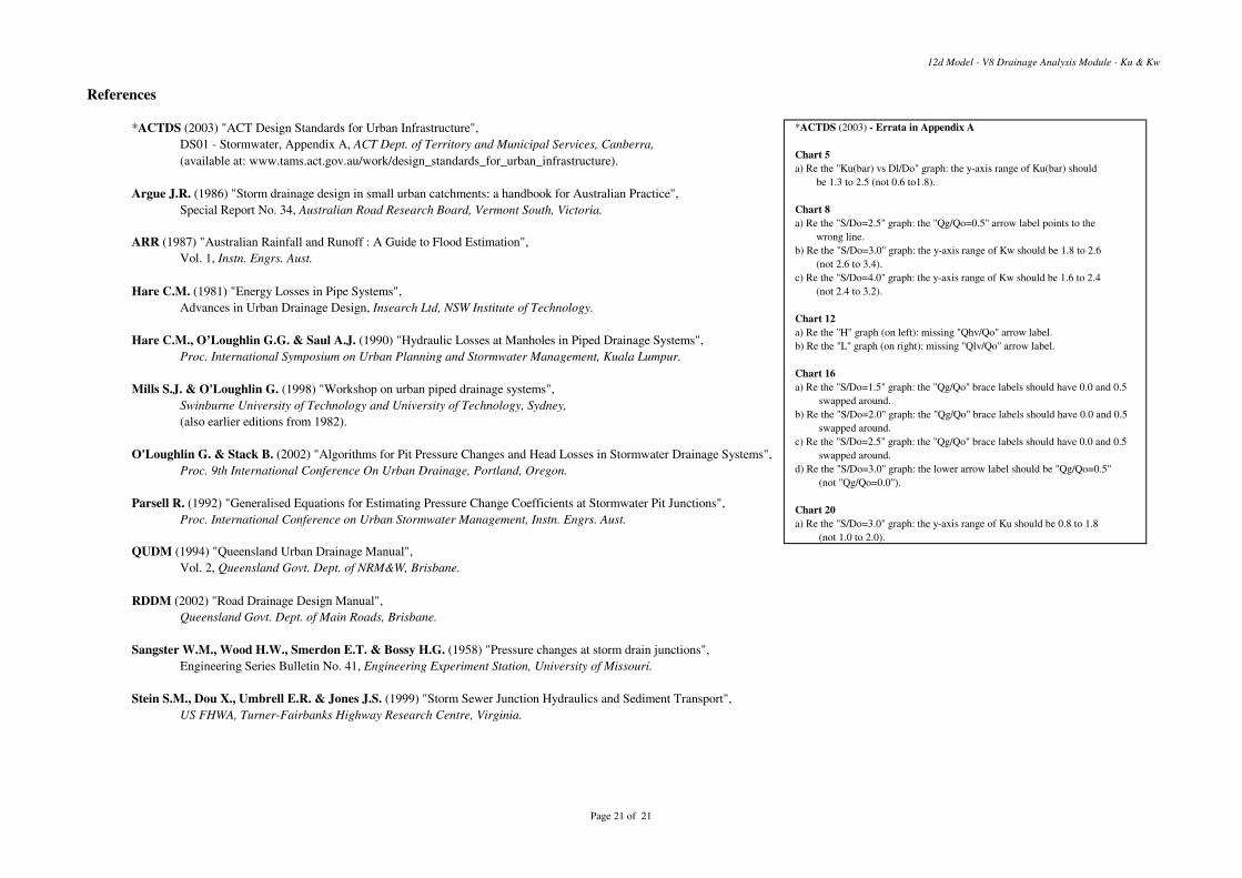
12d Model - V8 Drainage Analysis Module - Ku & Kw
References
*ACTDS (2003) "ACT Design Standards for Urban Infrastructure",
DS01 - Stormwater, Appendix A, ACT Dept. of Territory and Municipal Services, Canberra,
(available at: www.tams.act.gov.au/work/design_standards_for_urban_infrastructure).
Argue J.R. (1986) "Storm drainage design in small urban catchments: a handbook for Australian Practice",
Special Report No. 34, Australian Road Research Board, Vermont South, Victoria.
ARR (1987) "Australian Rainfall and Runoff : A Guide to Flood Estimation",
Vol. 1, Instn. Engrs. Aust.
Hare C.M. (1981) "Energy Losses in Pipe Systems",
Advances in Urban Drainage Design, Insearch Ltd, NSW Institute of Technology.
Hare C.M., O’Loughlin G.G. & Saul A.J. (1990) "Hydraulic Losses at Manholes in Piped Drainage Systems",
Proc. International Symposium on Urban Planning and Stormwater Management, Kuala Lumpur.
Mills S.J. & O'Loughlin G. (1998) "Workshop on urban piped drainage systems",
Swinburne University of Technology and University of Technology, Sydney,
(also earlier editions from 1982).
O'Loughlin G. & Stack B. (2002) "Algorithms for Pit Pressure Changes and Head Losses in Stormwater Drainage Systems",
Proc. 9th International Conference On Urban Drainage, Portland, Oregon.
Parsell R. (1992) "Generalised Equations for Estimating Pressure Change Coefficients at Stormwater Pit Junctions",
Proc. International Conference on Urban Stormwater Management, Instn. Engrs. Aust.
QUDM (1994) "Queensland Urban Drainage Manual",
Vol. 2, Queensland Govt. Dept. of NRM&W, Brisbane.
RDDM (2002) "Road Drainage Design Manual",
Queensland Govt. Dept. of Main Roads, Brisbane.
Sangster W.M., Wood H.W., Smerdon E.T. & Bossy H.G. (1958) "Pressure changes at storm drain junctions",
Engineering Series Bulletin No. 41, Engineering Experiment Station, University of Missouri.
Stein S.M., Dou X., Umbrell E.R. & Jones J.S. (1999) "Storm Sewer Junction Hydraulics and Sediment Transport",
US FHWA, Turner-Fairbanks Highway Research Centre, Virginia.
*ACTDS (2003) - Errata in Appendix A
Chart 5
a) Re the "Ku(bar) vs Dl/Do" graph: the y-axis range of Ku(bar) should
be 1.3 to 2.5 (not 0.6 to1.8).
Chart 8
a) Re the "S/Do=2.5" graph: the "Qg/Qo=0.5" arrow label points to the
wrong line.
b) Re the "S/Do=3.0" graph: the y-axis range of Kw should be 1.8 to 2.6
(not 2.6 to 3.4).
c) Re the "S/Do=4.0" graph: the y-axis range of Kw should be 1.6 to 2.4
(not 2.4 to 3.2).
Chart 12
a) Re the "H" graph (on left): missing "Qhv/Qo" arrow label.
b) Re the "L" graph (on right): missing "Qlv/Qo" arrow label.
Chart 16
a) Re the "S/Do=1.5" graph: the "Qg/Qo" brace labels should have 0.0 and 0.5
swapped around.
b) Re the "S/Do=2.0" graph: the "Qg/Qo" brace labels should have 0.0 and 0.5
swapped around.
c) Re the "S/Do=2.5" graph: the "Qg/Qo" brace labels should have 0.0 and 0.5
swapped around.
d) Re the "S/Do=3.0" graph: the lower arrow label should be "Qg/Qo=0.5"
(not "Qg/Qo=0.0").
Chart 20
a) Re the "S/Do=3.0" graph: the y-axis range of Ku should be 0.8 to 1.8
(not 1.0 to 2.0).
Page 21 of 21