13563: wps-2800 series system
TRANSCRIPT

Page 1©2001 Whelen Engineering Company Inc.Form No.13563C (011604)
Route 145, Winthrop Road,Chester, Connecticut 06412Phone: (800) 63SIRENPhone: (860) 526-9504Fax: (860) 526-4078Internet: www.whelen.comSales e-mail: [email protected] Service e-mail: [email protected]
Out
door
War
ning
WPS-2800 SERIESHIGH POWER VOICE
& SIREN SYSTEMINSTALLATION MANUAL
®
ENGINEERING COMPANY INC.

Page 2
Table Of Contents
Important Note To Installation Technicians .................................................................................. page 5
Section I : Site Selection........................................................................................................... page 6
Section II: Utility Pole Preparationa) Pole Selection...................................................................................................... page 7b) Component Dimensions .................................................................................... page 7
Section III: Equipment Mountinga) Pole Top Mounting Bracket .............................................................................. page 12b) Electronic Cabinet Mounting ........................................................................... page 14c) Siren Assembly Mounting (5 or less speaker cells) ......................................... page 16d) Siren Assembly Mounting (6 or more speaker cells)...................................... page 17e) Antenna Mounting (optional) ........................................................................... page 19f) Solar Panel Mounting (optional)....................................................................... page 20g) Determining Solar Panel Mounting Angle ...................................................... page 23
Section IV: Wiringa) Siren Connections .............................................................................................. page 24b) AC Wiring .......................................................................................................... page 26c) Batteries .............................................................................................................. page 28d) Landline.............................................................................................................. page 31
Section V: System Test ............................................................................................................. page 32
Illustrations
Fig. 1 Station Drawing ..................................................................................................................... page 3Fig. 2 Station Drawing (with optional Solar Panel) ...................................................................... page 4Fig. 3 Pole Top Mounting Bracket Dimensions ............................................................................. page 8Fig. 4 Type II Electronic Cabinet Dimensions ............................................................................... page 9Fig. 5 Type III Electronic Cabinet Dimensions ............................................................................. page 10Fig. 6 Antenna Mounting Bracket Dimensions ............................................................................. page 11Fig. 7 Pole Top Mounting Bracket .................................................................................................. page 13Fig. 8 Electronic Cabinet Mounting (Side View)........................................................................... page 14Fig. 9 Siren to Pole Top Mounting Bracket (Side View) ............................................................... page 18Fig. 10 Antenna Mounting Orientation.......................................................................................... page 19Fig. 11 Solar Panel Wiring Connections......................................................................................... page 21Fig. 12 Solar Panel Mounting Views............................................................................................... page 22Fig. 13 Siren Amplifier Connections .............................................................................................. page 25Fig. 14 AC Outlet Installation ......................................................................................................... page 27Fig. 15 Battery Connections (Type II Cabinet).............................................................................. page 29Fig. 16 Battery Connections (Type III Cabinet) ............................................................................ page 30Fig. 17 Landline Wiring................................................................................................................... page 31Fig. 18 System LED Indicators ....................................................................................................... page 33Fig. 19 Electronic Cabinet Front Panel .......................................................................................... page 34

Page 3
1 POINT RACK, SPOOLINSULATOR ANDSERVICE CLAMP FORAC SUPPLY.*
DRIP LOOP
WEATHER HEAD FORSERVICE ENTRANCE.*
2 POLE, 15A (MIN.), NEMA #3RA/C DISCONNECT.*
32.5"
HEIGHT
ModelNumber
Speaker Height(inches)
WPS-2800-1
WPS-2800-2
WPS-2800-3
WPS-2800-4
WPS-2800-5 (shown)
WPS-2800-6
WPS-2800-6A
WPS-2800-7
WPS-2800-8
WPS-2800-9
WPS-2800-10
18.7
31.1
43.5
56.0
68.4
80.8
80.8
93.2
105.6
118.1
130.5
GROUND WIRES TIEDTO GROUND RODPER SPEC. OR LOCALCODE.
(4) 10' SECTIONSOF 1” RIGID STEELCONDUIT.*
4 AWG (MINIMUM)SOLID COPPER WIREANTENNA GROUND.*
NOTE: AVOID SHARP BENDSIN THE GROUND WIRES
NOTE: ANTENNA INSTALLATIONMUST BE IN COMPLIANCE WITHALL FCC REGULATIONS.
4 AWG (MINIMUM)SOLID COPPER WIRECABINET GROUND.*
4 AWG (MINIMUM)SOLID COPPER WIRESPEAKER/ANTENNAGROUND.*
ALUMINUM TOCOPPER GROUNDLUG.
ALUMINUM TOCOPPER GROUNDLUG.
10'-12' (TYP)
SPEAKER, DRIVERSC) 1.00 DIA. CONDUIT-
ANTENNA CABLEB) .75 DIA. CONDUIT-
A.C. POWER INPUTA) .75 DIA. CONDUIT
GROUND RODS* PER SPEC, ORGROUNDING PER LOCAL CODES.
FLEX CONDUIT *
POLE SETTING DEPTHPER LOCAL CODES
A B C
50' (TYP)
68.4"
* CUSTOMER SUPPLIED
Fig. 1: Sample Station Drawing (AC Powered Battery Charger)

Page 4
32.5"
HEIGHT
ModelNumber
Speaker Height(inches)
WPS-2800-1
WPS-2800-2
WPS-2800-3
WPS-2800-4
WPS-2800-5 (shown)
WPS-2800-6
WPS-2800-6A
WPS-2800-7
WPS-2800-8
WPS-2800-9
WPS-2800-10
18.7
31.1
43.5
56.0
68.4
80.8
80.8
93.2
105.6
118.1
130.5
GROUND WIRES TIEDTO GROUND RODPER SPEC. OR LOCALCODE.
(4) 10' SECTIONSOF 1” RIGID STEELCONDUIT.*
OPTIONAL SOLARCHARGER PANEL
3/4” RIGIDSTEEL CONDUIT
10'-12' (TYP)
SPEAKER, DRIVERSC) 1.00 DIA. CONDUIT-
ANTENNA CABLEB) .75 DIA. CONDUIT-
SOLAR POWER INPUTA) .75 DIA. CONDUIT
GROUND RODS* PER SPEC, ORGROUNDING PER LOCAL CODES.
FLEX CONDUIT *
POLE SETTING DEPTHPER LOCAL CODES
A B C
50' (TYP)
68.4"
* CUSTOMER SUPPLIED
ALUMINUM TOCOPPER GROUNDLUG.
ALUMINUM TOCOPPER GROUNDLUG.
ALUMINUM TOCOPPER GROUNDLUG.
4 AWG (MINIMUM)SOLID COPPER WIREANTENNA GROUND.*
4 AWG (MINIMUM)SOLID COPPER WIRECABINET GROUND.*
4 AWG (MINIMUM)SOLID COPPER WIRESPEAKER/ANTENNAGROUND.*
NOTE: AVOID SHARP BENDSIN THE GROUND WIRES
NOTE: ANTENNA INSTALLATIONMUST BE IN COMPLIANCE WITHALL FCC REGULATIONS.
Fig. 2: Sample Station Drawing (Optional Solar Powered Battery Charger)

Page 5
An Important Note to the Installation Technicians...
The installation of this product requires careful planning and attention to detail! Theinstallation of this system should NOT be attempted by individuals without experience inthe disciplines necessary to this procedure (i.e. High-voltage electrical wiring, utility poleinstallation, etc.).
The installation of the WPS-2800 station provided in this manual follows a logicalprogression. This process is not arbitrary and was developed using information gatheredfrom both the manufacturer and experienced field technicians. Deviations from any of theseprocedures are not recommended unless they are in contradiction with local codes. IN ALLINSTANCES, LOCAL CODES TAKE PRECEDENT OVER PROCEDURES OUTLINEDHEREIN.
It is the responsibility of the installation technicians to read this entire manual. Theinstallation procedure should not begin until all personnel are familiar with the entireprocess. The overall process includes the following:
Installation sequence for 5or less cells1. Site Selection
2. Utility Pole Preparation
3. Mount Pole Top Bracket andGround Wire
4. Mount Electronic Cabinet to Pole
5. Mount Siren Assembly to Pole TopBracket and Conduit to Pole
6. Set Utility Pole
7. Prepare and Mount AntennaAssembly (if present)
8. Prepare and Mount Solar Panelsand Conduit (if present)
9. Installation of AC or Solar Serviceand Batteries
10. Confirm Proper System Operation
Installation sequence for 6or more cells1. Site Selection
2. Utility Pole Preparation
3. Mount Pole Top Bracket andGround Wire
4. Mount Electronic Cabinet to Pole
5. Set Utility Pole
6. Mount Siren Assembly to Pole TopBracket and Conduit to Pole
7. Prepare and Mount AntennaAssembly (if present)
8. Prepare and Mount Solar Panelsand Conduit (if present)
9. Installation of AC or Solar Serviceand Batteries
10. Confirm Proper System Operation

Page 6
Section I: Site SelectionThe site selection for the WPS-2800 requires careful consideration in order to achieve theoptimum coverage of the siren station. For a guideline to system planning, soundpropagation and site selection we direct the user to the Federal Emergency ManagementAgency’s “Outdoor Warning Systems Guide, CPG 1-17.”
The Location of the siren site should be reviewed for its compatibility with its surroundingssuch as private homes, schools and hospitals. The user is cautioned to consider the use ofhearing protection devices for service personnel working in close proximity to the speakercluster.
Access to the siren site is important from the standpoint of service, maintenance inspectionand access to a utility service connect.
Site locations for radio controlled units should be reviewed for radio reception.

Page 7
Section II: Utility Pole Preparation...a) Pole Selection
NOTE: This installation manual will address the procedures applicable to woodenutility poles of specific size and dimensions. Procedures for poles consisting ofother materials (steel, concrete, etc.) are not addressed within this document.The information presented, however, provides the necessary data andguidelines for a successful installation regardless of pole material.
A WPS-2800 system consisting of 5 or less speaker cells may use a Class 2 or Class 1 utilitypole. For systems consisting of 6 or more speaker cells, a Class 1 utility pole must be used.The length of the utility pole is consistent regardless of speaker cell quantity. The totallength of the pole referenced within this document is 60 feet. The pole depth of the set pole is10 feet, leaving a 50 foot pole as measured from the top of the pole to the ground. The utilitypole should be set in accordance with local codes.
The inside area of the pole top mounting bracket will accept a pole that is no greater than10.00” in diameter. On large scale projects, it is beneficial to order the pole to be “gained” toa top diameter of 9.5” +/- .50” for the top 30” section of the utility pole.
b) Component DimensionsThe utility pole may be pre-drilled prior to installation. The dimensions for all potentiallymounted equipment are as follows:

Page 8
4.5”
18.0”
7.5”
18.0”30.0”
13.5” 12.0”
1” Clearance BetweenTop Of Pole and InsideBottom Of Bracket
10.0” DIA. POLE (MAX.)
11.0” 10.0”
Fig. 3: Pole Top Mounting Bracket Dimensions

Page 9
3.5”
13.0”
27.7”
10.0”2.0”
LEFT SIDE VIEW
5.0”
32.8”
30.0”
.625 DIA.
REAR VIEW
28.0”
Fig. 4: Type II Electronic Cabinet Dimensions

Page 10
44.85”
30.0”
.687” DIA.
.687” DIA.
REAR VIEW
28.00
3.50”
38.5”
10.0”2.0”
LEFT SIDE VIEW
5.0”
25.25”
13.0”
Fig. 5: Type III Electronic Cabinet Dimensions

Page 11
IMPORTANT: Top of antennamast must be positioned atleast 1 inch below the bottomof the Pole Top Mounting Bracketregardless of antenna length.
Antenna Ground Lug,aluminum-to-copper,crimp or screw style.
4 AWG (minimum)solid copper wirespeaker ground.
4 AWG (minimum)solid copper wireantenna ground.
10.00
NOTE: Antenna installation mustbe in compliance with all FCCREGULATIONS.
Fig. 6: Antenna Mounting Bracket Dimensions

Page 12
Section III: Equipment Mountinga) Pole Top Bracket Installation...Items Required for installation (not included)....
(4) 5/8” x 14” Hex or Square head mounting bolts(4) 5/8” Hex or Square head nuts(8) 5/8” Flat Washer sized for the above referenced mounting bolt(4) 5/8” Lock Washer
1. Position the WPS-2800 pole top mounting bracket onto the top of the pole (see “Fig.7: Pole Top Mounting Bracket” on page 13). Make sure there is a 1 inch spacebetween the top of the pole and the pole top mounting bracket(see “Fig. 8: ElectronicCabinet Mounting (Side View)” on page 14).
NOTE: The inside area of the pole top mounting bracket will accept a pole that is nogreater than 10.00” in diameter. On large scale projects, it is beneficial toorder the pole to be “gained” to a top diameter of 9.5” +/- .50” for the top 30”section of the utility pole.
2. Using the pole top mounting bracket as a guide, drill four mounting holes throughthe pole at the bracket mounting hole locations. These holes should be sized toaccommodate the above referenced hardware.
3. Secure the bracket to the pole using the prescribed hardware (see “Fig. 7: Pole TopMounting Bracket” on page 13). Be sure to position all the associated hardware itemsin their proper order.
4. Secure a length of #4 solid copper wire to the pole top bracket grounding lug usingthe supplied nut. Make sure that this wire is of sufficient length to reach the groundwhen the pole has been set.
NOTE: All Hardware used for connecting equipment to the utility pole should beinspected for tightness between 12 to 18 months after installation. Someshrinkage of the newly treated utility pole may occur, loosening connections.

Page 13
9.5 Inches(+/- 0.5)
2
23
4
1
1 5/8” x 14” Square- (or Hex-) Head Bolt
2 5/8”
3 5/8” Split Lock Washer
4 5/8”
Flat Washer
Square- (or Hex-) Head Nut
Fig. 7: Pole Top Mounting Bracket

Page 14
b) Electronic Cabinet Mounting and Siren Connections...
MountingItems Required for installation (not included)....
For Type II & III cabinets
Qty. Qty.(Type II) (Type III) Description
(2) (3) 5/8” x 14” Hex or Square head mounting bolts(4) (6) 5/8” Flat Washer sized for the above mounting bolt(2) (3) 5/8” Split-Lock Washer(2) (3) 5/8” Hex or Square head nuts(1) (1) Aluminum-to-Copper lug sized for #4 ground wire (crimp
or screw style)(1) (1) Stainless Steel 1/4-20 x 2” bolt with appropriately sized flat
washer, split-lock washer and nut(1) (1) 10’ Copper ground rod
1
1 5/8” NUT
2 5/8” FLAT WASHER
3 5/8” SPLIT LOCK WASHER
4 5/8 X 14” BOLT
2 2 3 4
Fig. 8: Electronic Cabinet Mounting (Side View)

Page 15
The WPS-2800 siren case assembly may be installed onto the pole and wired before settingthe pole.
NOTE: Note: Due to the weight of the siren amplifier panel, the electronic cabinetassembly must be transported in an upright fashion to prevent distortion ofthe amplifier panel.
1. It is necessary for the installer to remember that two factors should determine theoptimum mounting location; the desired distance of the mounted cabinet to theground (typically 10 to 12 feet as measured from the bottom of the cabinet) andavailable speaker wire length (speaker assemblies are provided with a minimum of50 feet of speaker wire as measured from the bottom of the speaker assembly).
2. After the mounting location has been determined, drill an appropriately sized thru-hole into the pole at the top cabinet mounting hole. Install a bolt loosely into the holeand hang the cabinet onto the bolt.
3. With the cabinet fitted snugly to the pole, mark the surface of the pole at the lowermounting hole location inside the battery storage compartment. Type III cabinetswill have an additional mounting hole located in the second battery storagecompartment (see “Fig. 5: Type III Electronic Cabinet Dimensions” on page 10).Remove the cabinet from the pole and drill an appropriately sized thru-hole into thepole at the location(s) marked. Return the cabinet to its mounting location andsecure to the pole using the specified hardware.
4. Install an aluminum-to-copper lug (crimp or screw style) onto the #4 solid copperwire. Secure this to the cabinet mounting channel in hole supplied using stainlesssteel 1/4 - 20 hardware.
5. Install the ground rod as specified by local codes and connect both copper wires(from pole top mounting bracket and electronic cabinet) to this rod.
6. Install rigid steel conduit and necessary couplings from the speaker’s 1” conduitadapter to the 1” speaker conduit protruding from the base of the siren caseassembly. The first section of conduit may be installed onto the speaker’s basecasting prior to mounting the speaker to the pole top bracket. At the option of theuser, conduit unions may be used between the first section of conduit and the speakerbase casting and at the speaker cable conduit entrance to the siren case assembly.
NOTE: If the location of the conduit on the pole requires difficult conduit bends orcouplings, a section of metal bonded seal tight conduit NOT TO EXCEED 24INCHES may be used at the top of the pole and/or at the bottom of the pole asneeded for the speaker cable installation.
Batteries for the system should not be installed until the siren station is set in place,otherwise some leakage of the battery fluid may occur. Batteries should not be connected tothe system until AC power (or solar power if equipped) is available to the system to operatethe system’s battery charger.

Page 16
IMPORTANT! Before proceeding with the speaker installation, it is necessary for theinstaller to know the number of speaker cells to be installed on the utility pole. If thespeaker assembly to be installed consists of 5 (five) or less speaker cells, the speakerassembly may, at the installers discretion, be mounted onto the utility pole before thepole has been set. Siren assemblies consisting of 6 (six) or more speaker cells requirethe utility pole to be set prior to mounting. These larger assemblies also require a specialmounting procedure that must be followed to avoid damaging the assembly. Bothprocedures are outlined in the following sections.
c) Siren Assembly Mounting (5 or less speaker cells)...Hardware required for installation (factory included)....
(8) 20mm hex head nuts(8) 7/8” Flat Washers(4) 3/4” Split Lock Washers
1. Sling or cradle the utility pole in a safe manner so that the pole top is 3 to 4 feet offthe ground. This will allow the speaker assembly to clear the ground when installed.
2. Locate the 4 mounting studs on the bottom of the speaker assembly (see “Fig. 9:Siren to Pole Top Mounting Bracket (Side View)” on page 18).
3. Thread a 20mm hex nut onto each of the mounting studs until there is approximately1” of space between the top of the nuts and the bottom of the siren assembly. Thisspace will allow the speaker assembly to be leveled once the pole has been set.
4. Install a 7/8” flat washer onto each of the mounting studs.
5. Insert the four mounting studs through the mounting holes on the top of the pole topbracket. The bottom of the siren assembly should lie flat against the pole top bracket.
6. Install a 7/8” flat washer onto each of the mounting studs.
7. Install a 3/4” split lock-washer onto each of the mounting studs.
8. Thread a 20mm hex nut onto each of the mounting studs. Tighten this nut firmly tosecure the siren assembly to the pole top bracket.
At this point the pole should now be set. However, the installer may use their own discretionas to whether to mount the electronic cabinet onto the utility pole before the pole is set.
When the pole has been set, use the adjustment nuts (indicated in step 2) to adjust the sirenassembly until it is level.

Page 17
d) Siren Assembly Mounting (6 or more speaker cells)...Hardware required for installation (factory included)....
(8) 20mm hex head nuts(8) 7/8” Flat Washers(4) 3/4” Split Lock Washers
Items required (not included)
Crane, Bucket Truck or similar lifting deviceStraps
The larger siren assemblies (6 or more speaker cells) may only be mounted onto the pole topbracket after the pole has been set. Due to their increased mass and size, these assembliesmust be properly supported from the bottom of the assembly while being lifted into position.DO NOT ATTEMPT TO LIFT THE SIREN ASSEMBLY FROM THE TOP!
1. Locate the 4 mounting studs on the bottom of the speaker assembly (see “Fig. 9:Siren to Pole Top Mounting Bracket (Side View)” on page 18).
2. Thread a 20mm hex nut onto each of the mounting studs until there is approximately1” of space between the top of the nuts and the bottom of the siren assembly. Thisspace will allow the speaker assembly to be leveled once the pole has been set.
3. Install a 7/8” flat washer onto each of the mounting studs.
4. Insert the four mounting studs through the mounting holes on the top of the pole topbracket. The bottom of the siren assembly should lie flat against the pole top bracket.
5. Install a 7/8” flat washer onto each of the mounting studs.
6. Install a 3/4” split lock-washer onto each of the mounting studs.
7. Thread a 20mm hex nut onto each of the mounting studs. Tighten this nut firmly tosecure the siren assembly to the pole top bracket.
8. Use the adjustment nuts (indicated in step 2) to adjust the siren assembly until it islevel.

Page 18
20mm Hex Nut
7/8” Flat Washer
3/4” Lock Washer
1
1
2
3
2
3
Fig. 9: Siren to Pole Top Mounting Bracket (Side View)

Page 19
e) Antenna Mounting (optional)...
NOTE: Antenna installation must be in compliance with all FCC regulations.
The proper antenna bracket mounting location is determined by several considerations. Theantenna bracket should be positioned as high on the utility pole as is possible. However,under no circumstances should the top of the installed antenna mast be any closer than oneinch from the bottom of the Pole Top Mounting Bracket (see “Fig. 6: Antenna MountingBracket Dimensions” on page 11). Be sure to ground the antenna bracket as shown using 4AWG solid copper wire. The antenna cable provided by the factory is 35 feet in length.
It is also important to remember that the antenna MUST be mounted on the side of theutility pole that faces the transmitter (see below)
Fig. 10: Antenna Mounting Orientation
Refer to the installation sheet included with your antenna kit for further informationregarding cable connections and antenna trimming.
Improper Antenna Orientation
Antenna
Pole
Pole
Pole
Correct Antenna Orientation
Pole Pole
Pole
Base
Station
Base
Station

Page 20
f) Solar Panel Mounting (optional)...The solar panel must be installed so that it is directly facing the earth’s equator with anunobstructed view. Failure to orient the solar panel in this way will result in significantlyreduced charging effectiveness.
The most critical aspect of properly mounting the solar panel involves achieving theoptimum tilt angle. The tilt angle is determined by the distance between the upper and lowermounting brackets, as shown.
Refer to page 21 for electrical connection information.
Refer to page 22 for general solar panel mounting.
Refer to page 23 for information on determining your specific mounting angle.
Run rigid steel conduit from the solar panel to the 3/4” AC knockout located at the bottomof the siren case assembly. A section of up to 24 inches of metal bonded seal tight conduitmay be utilized where conduit connections to the solar panel or electronic cabinet are notconveniently accomplished with rigid steel conduit and fittings. This conduit should besealed to prevent insects and pests from entering the siren case assembly.

Page 21
-
+
-
+
SOLAR REGULATOR(SEE NOTES 2 & 6)
NOTE 5
NOTE 4
STRIP CABLE BACKTHIS END AS REQUIRED
SOLAR PANELS(REAR VIEW)
BLK(GND)
RED(+26V)
3/4" FLEX CONDUIT
(CUSTOMER SUPPLIED)
NOTES:
Wire entrance hardware per local codes,water tight as required (3 places).
Fork terminals & fast-ons included withinstallation kit.
Electrical boxes shown with covers removed.
Cable to be stripped back 26” at solar panelend.
Supplied by Whelen, included with installationkit.
Install fast-ons to the solar regulator end of thecable only after the proper length of cable hasbeen achieved, leaving at least a 6’ service loop.
1 -
2 -
3 -
4 -
5 -
6 -
-
+
NOTE 3
NOTE 1
NOTE 2
JUMPER
RED WIREFROM CABLE
BLACK WIREFROM CABLE
NOTE 3
-
+
NOTE 1
JUMPER
NOTE 2
NOTE 1
+
Fig. 11: Solar Panel Wiring Connections

Page 22
Solar Panel Mounting Bracket Hardware
Description
5/16 - 18 X 1” Hex Head Bolt
5/16 - 18 Elastic Stop Nut
5/16” Flat Washer
Qty.
8
8
8
Remember to ALWAYSmount panels facing theEarth’s Equator
DimensionA
8.00”
8.00”
LowerLatitudes
HigherLatitudes
Fig. 12: Solar Panel Mounting Views

Page 23
TiltAngle
TiltAngle
TiltAngle
10111213141516171819202122232425262728293031
32333435363738394041424344454647484950515253
54555657585960616263646566676869707172737475
50.4950.3450.1649.9749.7749.5549.3249.0848.8248.5448.2547.9547.6347.3046.9546.5946.2245.8345.4345.0244.6044.16
43.7143.2442.7742.2841.7841.2640.7440.2039.6539.1038.5337.9537.3636.7536.1435.5234.8934.2533.6032.9532.2831.61
30.9330.2429.5428.8428.1327.4126.6925.9625.2324.5023.7623.0122.2721.5220.7720.0219.2718.5217.7717.0216.2815.54
Dimension A(inches)
Dimension A(inches)
Dimension A(inches)
g) Determining Solar Panel Mounting Angle1. Determine the LATITUDE of your location.
2. Find your Latitude on the table below and not the corresponding Tilt Angle.
LATITUDE TILT ANGLE
0° to 9° 75° = Tilt Angle10° to 20° 85° minus LATITUDE = Tilt Angle21° to 45° 80° minus LATITUDE = Tilt Angle46° to 65° 75° minus LATITUDE = Tilt Angle66° to 75° 10° minus LATITUDE = Tilt Angle
3. Locate your TILT ANGLE in the list below. For every TILT ANGLE, there is a corresponding “Dimension A”. “Dimension A” represents the distance from the bottom of the upper mounting bracket to the bottom of the lower mounting bracket.
example 1: example 2:Location LATITUDE is 30° Location LATITUDE is 7°80° - 30° = 50° Tilt Angle 7° = 75° Tilt Angle50° Tilt Angle = 33.60” Dimension A 75° Tilt Angle =15.54” Dimension A

Page 24
Section IV: Wiringa) Siren ConnectionsThe type of speaker harness you receive depends on the number of speaker cells present.For systems consisting of 1 to 5 speaker cells, a 5-pair harness cable is provided. This cablehas 5 BLACK wires numbered 1 to 5 and 5 RED wires numbered 1 to 5. For systems with 6to 10 speaker cells, a 10-pair harness cable is used. This wires in this cable are designated asfollows:
10 BLACK wires numbered 1 to 1010 RED wires numbered 1 to 10
In systems with unused wires, dress the unused wires so they are out of the way. Do not cutthese wires, as they can be used to replace damaged wires in the future.
NOTE: The following procedure provides the information necessary for successfullyconnecting the siren harness wires to their designated amplifiers. Dependingupon the distance between the siren base and the electronic cabinet, there willbe varying lengths of wire remaining in the cabinet. It is the installersresponsibility to properly trim and dress these wires in a fashion that not onlyleaves the wires organized, but also includes a service loop of suitable length.
1. Locate the siren wiring harness where it enters the electronic cabinet.
2. Locate the BLACK and RED wires marked 1 on their insulation. These wires aredesignated for connection to siren amplifier 1.
3. Route these wires through the cabinet’s wire loom and connect to Amp 1 (see “Fig.13: Siren Amplifier Connections” on page 25).
4. Repeat steps 2 and 3, substituting the appropriate number for all remaining amplifiers.
5. When all amplifiers have been wired, install loom cover.
Authors Note: Prior to this writing, systems with 6 to 9 speaker cells received a 9-pair harnesscable, with Red and Black wires numbered 1 to 9. Systems with 10 speaker cells received two, 5-pair cables. One cable used Red and Black wires numbered 1 to 5, while the remaining cable usedRed and Black wires numbered 1A to 5A (to be used for amplifiers 6 thru 10).

Page 25
Amp5
Amp4
Amp3
Amp2
Amp1
OUT1
OUT1
OUT1
OUT1
OUT1
Red wire 1
Red wire 6
Red wire 7
Red wire 8
Red wire 9
Red wire 10
Red wire 2
Red wire 3
Red wire 4
Red wire 5
Route amplifier wires through wire loomat appropriate locations.
Install loom cover after all wires havebeen routed.
Black wire 1
Black wire 6
Black wire 7
Black wire 8
Black wire 9
Black wire 10
Black wire 2
Black wire 3
Black wire 4
Black wire 5
GND1
OUT1
GND1
OUT1
GND1
OUT1
GND1
OUT1
GND1
OUT1
GND1
GND1
GND1
GND1
GND1
Amp7
Amp6
Amp10
Amp9
Amp8
Fig. 13: Siren Amplifier Connections

Page 26
b) AC WiringAn AC Service (Single Phase only) with an acceptable disconnect is required. A 15 amp(minimum) 120 VAC circuit is recommended.
Locate the service on the pole according to local codes, taking care that the service entrancewill meet height requirements once the pole is set into place.
The WPS-2800 includes a 15 amp, 120 VAC outlet. The cabinet’s battery charger plugs intoone of the receptacles. The remaining receptacle is available for use by service personnel(see “Fig. 14: AC Outlet Installation” on page 27).
NOTE: A section of up to 24 inches of metal bonded seal tight conduit may be utilizedwhere conduit connections to the siren case assembly are not convenientlyaccomplished with rigid steel conduit and fittings.
Each WPS-2800 siren system is supplied with a Lightning arrestor which is to be installedon the AC service. Local codes should be reviewed and followed to establish the connectionof this device on the primary or secondary side of the disconnect.
NOTE: The location of the siren site should be reviewed for the quality of the ACservice. AC power sources that are subject to excessive power surges ortransients are not acceptable.
The AC charger is simply plugged into an AC duplex outlet (factory included) installed asfollows:
1. Remove the cover from the 4” x 4” box.
2. Position the 3/4” knock-out in the box above the 3/4” knockout in the cabinet.
3. Attach a flex fitting (not included) through the cabinet and the box. This will securethe box to the cabinet.
4. Connect the AC service to the leads on the cover assembly.
5. Attach the cover to the box.
6. Attach ground wire (GREEN) to cabinet ground stud above the installed outlet.

Page 27
LOCATE 4 x 4 BOX HERE.
ATTACH THE AC SERVICE FITTING AS SHOWN.
SECURE GROUND WIRES HERE.
Fig. 14: AC Outlet Installation

Page 28
c) Batteries1. Make sure that the system battery switch is in the OFF position.
2. Install the batteries included with your system and connect them as shown in theillustration representing your cabinet type. MAKE SURE TO OBSERVE THEPOLARITY OF THE TERMINALS BEFORE MAKING ANY CONNECTIONS.
NOTE: For battery wiring, DC wiring conventions are used (BLACK is ground (-)).
For Type II Cabinets (see “Fig. 15: Battery Connections (Type II Cabinet)” on page 29)
Type III Cabinets (see “Fig. 16: Battery Connections (Type III Cabinet)” on page 30)
3. Rotate the system battery switch to the ON position.
4. Plug the battery charger into the AC outlet.
5. Verify system operation as outlined in the system maintenance check list.

Page 29
(+) (-) (+) (-)
OFF
ON
SystemBatterySwitch
Fig. 15: Battery Connections (Type II Cabinet)

Page 30
(+) (-) (+) (-)
(+) (-) (+) (-)
OFF
ON
SystemBatterySwitch
Fig. 16: Battery Connections (Type III Cabinet)
Page 31
1 1 48
LANDLINE AUDIO OUT
N/C N/C
LANDLINE AUDIO OUT
LANDLINE AUDIO IN
LANDLINE AUDIO IN
WIRE HARNESS
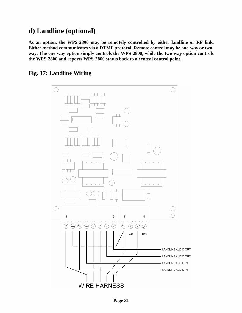
d) Landline (optional)As an option. the WPS-2800 may be remotely controlled by either landline or RF link.Either method communicates via a DTMF protocol. Remote control may be one-way or two-way. The one-way option simply controls the WPS-2800, while the two-way option controlsthe WPS-2800 and reports WPS-2800 status back to a central control point.
Fig. 17: Landline Wiring

Page 32
Section V: System Test...After the installation of the WPS-2800 station has been completed, a basic system check isrecommended to confirm that the system is functioning properly. Before initiating thesetests, locate the system LED’s on the main control board mounted to the cabinet door (see“Fig. 18: System LED Diagnostic Indicators” on page 33).
1. Confirm that the ACTIVE light on the control board is flashing at a rate of a 1/2second on and a 1/2 second off.
2. Press the SI TEST® button on the siren front panel and check to make sure that allthe siren amplifier diagnostic LED’s illuminate for 5 seconds. These LED’s arelocated on the front of the cabinet door.
3. After the amplifier LED’s turn off, check to see if the AC, DC, PARTIAL and FULLLED’s are on.
If one of your amplifier lights did not illuminate during this test then refer to the procedurebelow to troubleshoot the problem.
This procedure may be used when the Partial or Full LED’s indicate a failure.
NOTE: In order for a “Full” indication to be valid, the “Partial” LED must also beon.
1. Press the SI TEST® button located on the front panel of the electronic cabinet. Eachamplifier has a red LED diagnostic indicator that is visible on the front panel (see“Fig. 19: Electronic Cabinet Front Panel (Type II).” on page 34).
2. A SI TEST® will cause each amplifier’s diagnostic indicator to turn on. If one ormore do not turn on, proceed to step 3. If all indicators turn on, the siren amplifiersare functioning properly.
3. Open the front panel and remove the speaker driver from the amplifier that did notlight and install it onto an amplifier that did light. For example: If amplifier 1 did notlight but amplifier 2 did, install speaker 1 on amplifier 2 and speaker 2 on amplifier1. This will indicate if the failure was with the speaker or the amplifier. For moreinformation on troubleshooting the system, refer to the advanced trouble shootingmanual.

Page 33
1 2
3 4 5 6
8
7
9
NOTE: In some instances, optionalcircuit boards may be located directlyabove these LED’s.
1 6
2 7
3
8
4
95
Fault (RED) - Normally off. When aproblem has been detected, this LEDwill be on.
DC - Normally on. If no DC voltage wasdetected during a siren tone or ,this LED will be off.
SI TEST®
Active - This LED normally flashes at arate of once every half seconds. Whena problem has been detected, this LEDwill stop flashing or be off. Also indicatesreceipt of DTMF data by flashing at afaster rate for about 1 second.
AC - Normally on. If no DC voltage wasdetected during a siren tone or ,this LED will be off.
SI TEST®
Rotator - This LED is not used with theWPS-2800 system.
Squelch - Normally off. This LED will lightwhen the station is receiving a radiobroadcast. If equipped with the optionalreceive tone/squelch tone, the LED willonly light when the receive frequencyand sub-audible tone squelch frequencytone is detected.Full - Normally on. If a siren amplifier
does not operate properly during atone activation or SI TEST®, this LED will be off.
PTT - Normally off. This LED will light whenthe station transmitter is active.Partial - Normally on. If all siren
amplifiers do not operate properly duringa , this LED will beoff. If at least one amplifier operates properly,it will remain on.
tone activation or SI TEST®
Fig. 18: System LED Diagnostic Indicators

Page 34
S E L E C T C O M M A N D
CANCEL
TRANSMITAUDIO
WAIL ATTACK ALERT
WHOOP HI-LO AIRHORN
SI-TEST
DVM-TEST OPTION
STATUSTRANSMIT
CW CCW
Siren AmplifierDiagnostic LED’s(5 cell system shownfor reference)
Amp.1
Amp.2
Amp.3
Amp.4
Amp.5
Fig. 19: Electronic Cabinet Front Panel (Type II).