13th canadian masonry symposium h alifax...
TRANSCRIPT

13 T H C A N A D I A N M A S O N R Y S Y M P O S I U M H A L I F A X , C A N A D A JUNE 4TH – JUNE 7TH 2017
IN-PLANE AND OUT-OF-PLANE PERFORMANCE OF MASONRY INFILL
STRENGTHENED WITH FABRIC REINFORCED CEMENTITIOUS MATRIX
Sagar, S. Lalit1; Singhal, Vaibhav2 and Rai, Durgesh C.3
ABSTRACT The efficacy of a composite overlay known as Fabric Reinforced Cementitious Matrix (FRCM) was assessed for seismic strengthening of masonry infill walls in the present experimental program. Six half-scale masonry infilled RC frames with different FRCM configurations were tested to study the effect of method of the fabric application, provision of mechanical anchors and orientation of the fabric on the performance of the strengthened infill walls. Two methods of fabric application were employed to examine the effect on FRCM: direct application and sandwich application. A unique loading protocol was used for bi-directional loading of the specimen, consisting of successive application of slow cyclic drifts for in-plane loading and shake-table generated ground motion for out-of-plane loading. The strengthened infill walls could safely withstand a storey drift in excess of 2.20%, preserving the structural integrity without jeopardizing its out-of-plane capacity. The direct mode of application of the fabric exhibited a superior performance with better bond characteristics and stress redistribution. The mechanical anchors were effective in limiting the separation of the infill from the frame, resulting in enhanced bi-directional response. The orthogonal orientation of the fabric was more effective compared to the oblique orientation for FRCM strengthening.
KEYWORDS: composite, FRCM, FRP, infill walls, masonry, seismic
INTRODUCTION Reinforced concrete (RC) construction with masonry infill walls is one of the most widely practiced construction typologies across the world. Though the infills are helpful in increasing the lateral stiffness of structures, their brittle nature and poor bond with the surrounding frame makes them vulnerable to collapse. Masonry walls strengthened with fiber reinforced polymer (FRP)
1 Former Graduate Student, Dept. of Civil Eng, Indian Institute of Technology Kanpur, Kanpur, UP, India,
[email protected] 2 Assistant Professor, Dept. of Civil and Envn. Eng., Indian Institute of Technology Patna, Bihta, Bihar, India,
[email protected] 3 Professor, Dept. of Civil Eng., Indian Institute of Technology Kanpur, Kanpur, UP, India, [email protected]

sheets and rods have shown considerable improvements in strength and ductility over the unstrengthened specimens [1, 2]. But, FRP suffers from drawbacks such as poor durability, inability to apply on wet surfaces, and other problems associated with the use of organic binders [3, 4]. In order to increase the scope of using FRP in practical applications, the organic binders have been replaced with cementitious matrices, resulting in a composite system known as fabric reinforced cementitious matrix (FRCM).
Past experimental studies suggest that the FRCM strengthened masonry walletes tested under in-plane shear and out-of-plane flexural loads have shown considerably good performance in terms of strength and deformability [3, 4]. However, the studies on FRCM strengthened infill walls, especially under dynamic loads are limited. In this study, the bidirectional behavior of the infill walls has been studied under a unique loading protocol to simulate a more realistic behavior of the masonry panel under in-plane and out-of-plane loads [5]. The efficacies of different strengthening configurations were evaluated in the tests by varying the three parameters, namely, mode of fabric application, provision of mechanical anchors and orientation of fabric.
EXPERIMENTAL PROGRAM
Masonry units, prisms and concrete Specially made half-scale burnt clay bricks (130 mm × 64 mm × 43 mm) and lime-cement mortar of mix proportion 1:1:6 was used for laying the masonry walls. The physical and mechanical properties of these chosen half-scale bricks correlate well with that of full-scale bricks [6]. The average compressive strength of brick units was 14.4 MPa with a coefficient of variation (COV) of 11.5%. Cement mortar of mix proportion 1:4 was used for plastering the walls. The average compressive strength of mortar used for masonry and plaster was 8.2 MPa (COV = 16.9%) and 15.0 MPa (COV = 13.6%), respectively. The average compressive strength of masonry was 8.2 MPa (COV = 7.5%). Concrete of mix proportions 1:1.583:2.814 was used in RC frame members and its average compressive strength was 33.83 MPa (COV = 3.7%). The yield strength of 12 mm and 6 mm diameter bars were 509 MPa and 430 MPa, respectively.
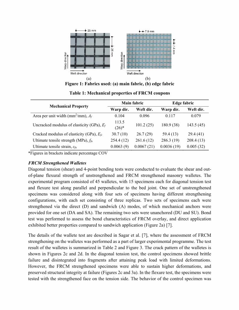
Fabrics and Tensile Properties of FRCM Coupons Two types of FRP sheets/fabrics, namely main/panel and edge fabrics were used for FRCM strengthening (Figure 1). The main fabric was placed on the entire surface of the infill panel, and the edge fabric was placed in the form of strips along the frame-infill interface. FRCM coupon tests were performed based on the guidelines of AC 434 [7, 8], to characterize tensile properties of FRCM of the main and edge fabrics. Results of coupon test are summarised in Table 1.
Mode of Fabric Application In this study, two methods of fabric application were employed. In the direct application, the fabric was placed on the surface of masonry directly, and then coated with a single cement mortar layer of 6 mm thickness. Whereas in sandwich application, the fabric was placed between two mortar layers of 2 mm and 4 mm thicknesses.
(a) (b)
Figure 1: Fabrics used: (a) main fabric, (b) edge fabric
Table 1: Mechanical properties of FRCM coupons
Mechanical Property Main fabric Edge fabric
Warp dir. Weft dir. Warp dir. Weft dir.
Area per unit width (mm2/mm), Af 0.104 0.096 0.117 0.079
Uncracked modulus of elasticity (GPa), Ef 113.5 (26)*
101.2 (25) 180.9 (38) 143.5 (45)
Cracked modulus of elasticity (GPa), Efc 30.7 (10) 26.7 (29) 59.4 (13) 29.4 (41)
Ultimate tensile strength (MPa), ffu 254.4 (12) 261.6 (12) 286.3 (19) 208.4 (13)
Ultimate tensile strain, εfu 0.0063 (9) 0.0067 (21) 0.0036 (19) 0.005 (32)
*Figures in brackets indicate percentage COV
FRCM Strengthened Walletes Diagonal tension (shear) and 4-point bending tests were conducted to evaluate the shear and out-of-plane flexural strength of unstrengthened and FRCM strengthened masonry walletes. The experimental program consisted of 45 walletes, with 15 specimens each for diagonal tension test and flexure test along parallel and perpendicular to the bed joint. One set of unstrengthened specimens was considered along with four sets of specimens having different strengthening configurations, with each set consisting of three replicas. Two sets of specimens each were strengthened via the direct (D) and sandwich (A) modes, of which mechanical anchors were provided for one set (DA and SA). The remaining two sets were unanchored (DU and SU). Bond test was performed to assess the bond characteristics of FRCM overlay, and direct application exhibited better properties compared to sandwich application (Figure 2a) [7].
The details of the wallete test are described in Sagar et al. [7], where the assessment of FRCM strengthening on the walletes was performed as a part of larger experimental programme. The test result of the walletes is summarized in Table 2 and Figure 3. The crack pattern of the walletes is shown in Figures 2c and 2d. In the diagonal tension test, the control specimens showed brittle failure and disintegrated into fragments after attaining peak load with limited deformations. However, the FRCM strengthened specimens were able to sustain higher deformations, and preserved structural integrity at failure (Figures 2c and 3a). In the flexure test, the specimens were tested with the strengthened face on the tension side. The behavior of the control specimen was

brittle, with mid-span displacements of less than 1 mm (Figure 3b, 3c). The FRCM strengthening was effective in achieving a ductile behavior as the displacements were substantially increased with redistribution of stresses in masonry, and the mechanical anchors were helpful in containing the broken fragments of the wallete (Figure 2d).
(a) (b) (c) (d)
Figure 2: (a) Bond test – Cohesive failure in direct application, (b) Bond test – Interlaminar failure in sandwich application, (c) Diagonal tension test – Specimen DU at failure, (d)
Flexure test parallel to bed-joint – Ductile failure of specimen SA.
Table 2: Summary of the Tests on Walletes
Spec.
Diagonal tension test Flexure test
Parallel to bed-joint Normal to bed-joint Shear strength
(MPa) Pseudo-ductility
Peak strength (MPa)
Ductility index
Peak strength (MPa)
Ductility index
C 1.78 (8)* 1.00 1.07 (17) 1.0 1.46 (2) 1.0 DU 1.75 (15) 8.06 (5) 2.13 (17) 6.43 (22) 2.26 (28) 6.99 (52) DA 1.54 (6) 9.15 (51) 1.66 (15) 7.55 (7) 2.01 (12) 7.28 (4) SU 1.72 (3) 8.02 (48) 2.23 (7) 6.72 (14) 2.24 (5) 10.92 (39) SA 1.86 (2) 10.92 (26) 2.22 (12) 7.79 (27) 2.25 (20) 5.03 (6)
* Figures in brackets () indicate percentage coefficient of variation (COV)
(a) (b) (c)
Figure 3: Wallete test results: (a) Diagonal tension test, (b) Flexure test – Parallel to bed-joint, (c) Flexure test – Perpendicular to bed-joint.
0.0
0.5
1.0
1.5
2.0
0 0.005 0.01 0.015 0.02
C
SU
SA
She
ar s
tres
s (M
Pa
)
Shear strain
0.0
0.5
1.0
1.5
2.0
2.5
3.0
0 2 4 6 8 10
C
SU
SA
Fle
xura
l str
ess
(MP
a)
Deflection (mm)
0.0
0.5
1.0
1.5
2.0
2.5
3.0
0 2 4 6 8 10
C
DU
DA
Fle
xura
l str
ess
(MP
a)
Deflection(mm)

Half-scaled masonry infilled RC frames Details of test matrix are shown in Table 3. The geometric and reinforcement details for the typical RC frame with infill and the fabric layout for specimen DA45 are presented in Figures 4a and 4b, respectively. The test program consisted of six half-scale clay brick masonry infill walls.
Table 3: FRCM strengthening configurations for the test specimens
Specimen No.
Mode of fabric application
Mechanical anchors
Orientation of fabric with bed-joint
Symbol
1 Control specimen Not applicable CS
2 Direct No 0-90o DU0-90
3 Direct Yes 0-90o DA0-90
4 Sandwich No 0-90o SU0-90
5 Sandwich Yes 0-90o SA0-90
6* Direct Yes ±45o DA45*
*Strengthening configuration of specimen 6 was selected based on test results of specimens 2 to 5
Fabrication of test specimen and FRCM strengthening The constructed RC frame was infilled with half-scaled burnt clay brick masonry in running bond flush with the front surface of the frame. The FRCM strengthening was performed on the front face of the infill only, and the back face was plastered with cement mortar. FRCM strengthening layout for specimen DA45 after fixing the mechanical anchors is represented in Figure 4b. The spacing of the mechanical anchors was provided such that the shear capacity of the anchors was greater than the tensile strength of the fabric in order to prevent the failure of anchors. Lap splicing of 150 mm was kept for the overlapping main fabric and also beyond the frame-infill interface as per the guidelines of ACI 549.4R [9].
TEST SETUP A unique testing method proposed by Komaraneni et al. [5] and Singhal and Rai [10], was used in the present study for the sequential out-of-plane and in-plane loading. A uniaxial shake table was used for out-of-plane loading, and a 500 kN actuator was used for in-plane loading. Adequate lateral supports were provided to simulate the boundary condition; a pre-compression stress of 0.1 MPa was maintained on the wall and a load of 25 kN was applied on columns, using a flexible wire rope arrangement in order to simulate the gravity load. Artificial mass in form of lead blocks were attached on the wall to simulate the inertial forces generated due to out-of-plane ground motion.
Loading History and Test Procedure The specimens were subjected to simulated earthquake ground motions generated by a shake table in the out-of-plane direction. The N21E component of the 1952 Taft earthquake was chosen for the out-of-plane target ground motion [10]. The ground motion, with the time axis compressed by a factor of 1/√2 (to satisfy the dynamic similitude relations) and scaled to a PGA value of 0.4g was

defined as Level V motion, as its 5% damped response spectra corresponds well with the design response spectrum for a design earthquake, with a PGA of 0.36g in the Zone V of the Indian Seismic Code IS 1893 [11]. Similarly, the Taft motion scaled to PGA values of 0.1g, 0.16g and 0.24g corresponding to Zone II, III and IV of Indian Seismic Code were referred to as Level II, III, and IV motions, respectively. Also, Level I ground motion was defined as the Taft motion scaled to a PGA of 0.055g. In-plane loading consisted of displacement controlled slow cyclic drifts, which were selected as per the guidelines of ACI 374.05 [12]. The loading history consisted of gradually increasing storey drifts from 0.10% to 2.75%. Each displacement cycle was repeated for three times at each drift ratio.
(a) (b)
Figure 4: Test specimen: (a) Geometric and reinforcement details, (b) Layout of FRCM strengthening of specimen DA45
The loading sequence used for testing is presented in Figure 5 [10]. The load test started with the out-of-plane shake table motions consisting of a series of incremental Taft motions from Level I to V, with the white noise tests in between. Further, the specimen was subjected to quasi-static in-plane cyclic loading up to a drift level of 0.50%. After the in-plane loading, the specimens were subjected to alternate cycles of out-of-plane and in-plane loading until the failure.
Figure 5: Details of loading sequence (DL = In-plane drift level and DS = Damage state)
Till Failure

RESULTS AND DISCUSSION
Physical Observations during the tests The infill panel of the control specimen experienced several cracks under in-plane loads, and disintegrated owing to its brittle nature. Subsequently, the panel experienced partial collapse under out-of-plane loading. However, the infill panels of the FRCM strengthened specimens exhibited ductile behavior by preserving the structural integrity of the infill, and the excessive deflections were effectively controlled under out-of-plane loading. The failure patterns of the wall specimens are presented in Figure 6.
In the control specimen CS and unanchored specimens DU0-90 and SU0-90, separation of the infill panel from the frame was observed, leading to concentration of stresses at the corners of infill panel. Shear cracks were formed at the column ends as extensions of existing diagonal cracks in the infills, characterized by abrupt drop in the in-plane load capacities. In the specimens DA0-90 and SA0-90, the mechanical anchors restricted the tendency of the infill wall to separate from the frame, and a well distributed cracking pattern was observed in the infills (Figure 6c and 6e), along with gradual decrease in their load capacities. The fabric of specimen DA45 experienced overstressing due to the oblique orientation of fabric. Though bed-joint cracks were formed, the infill was ineffective in resisting the stresses due to sliding of masonry, with the observation of extensive rupture of fabric and walking-out of the infill panel.
(a) (b) (c)
(d) (e) (f)
Figure 6: Damage pattern of the specimens at the end of the test: (a) CS, (b) DU0-90, (c) DA0-90, (d) SU0-90, (e) SA0-90, and (f) DA45.
In-Plane Load Displacement Response The in-plane behavior of the specimens is evaluated in terms of the load capacity, displacement ductility, strength degradation and energy dissipation, and summarized in Table 4. The hysteretic
Crushing of bricks Flaking of plaster

response of all specimens with the summary of strengths and key damage observations are shown in Figure 7.
The control specimen showed an average in-plane load capacity (Rmax) of 227.2 kN, and the average load capacities of the strengthened specimens varied from 247.1 kN to 284.0 kN. The anchored and the unanchored specimens showed comparable in-plane capacities. The specimen DU0-90 showed slightly (8%) higher strength compared to its anchored counterpart DA0-90, which could be attributed to the variations inherent in the properties of masonry. However, the anchored specimens exhibited a superior post-peak behavior with gradual decrease of the load capacities, and symmetric response along both directions of loading. Displacement ductility (Δ) was given
by the ratio of post-peak displacement (u), corresponding to Rw = 0.8Rmax in the post-peak regime
to yield displacement (y), corresponding to 0.6Rmax prior to attaining the peak load. Wall DA0-90 showed the highest drift ratio at yield of 0.38% among all the specimens, which was consistent with the physical observations of the wall, where the onset of cracking was considerably delayed.
Table 4: Summary of observed response for all specimens
Wall Ultimate load, Rmax
(kN)
y*
(mm) u
(mm) Displ.
ductility, Δ=u/y
Strength degradation,
Csd
Cumulative energy (kN-m)
CS +228.5 -227.0
+2.8 -2.8
+23.6 -38.3
8.3 (+) 13.8 (-)
0.38 (+) 0.59 (-)
10.7
DU0-90 +270.2 -264.0
+3.9 -4.5
+23.3 -21.7
6.0 (+) 4.8 (-)
0.50 (+) 0.37 (-)
13.5
DA0-90 +250.7 -243.5
+4.5 -6.3
+33.9 -31.5
7.5 (+) 5.0 (-)
0.56 (+) 0.57 (-)
64.7
SU0-90 +251.5 -248.8
+3.1 -3.5
+20.6 -15.0
6.6 (+) 4.3 (-)
0.18 (+) 0.16 (-)
12.9
SA0-90 +270.0 -287.3
+3.6 -3.7
+34.4 -26.5
9.5 (+) 7.1 (-)
0.36 (+) 0.33 (-)
47.3
DA45 +292.1 -275.9
+4.2 -3.6
+24.2 -28.6
5.1 (+) 7.9 (-)
0.33 (+) 0.39 (-)
84.4
*y = yield displacement corresponding to Rcr i.e., 60% of peak load #u = post-peak displacement corresponding to the load Rw i.e., 80% of peak load
To indicate the deterioration in the strength of the wall after reaching peak strength, a strength degradation factor Csd was used, which was given by the ratio of residual strength, Rr to peak strength, Rmax. The energy dissipation of the specimens was obtained by computing the area enclosed by the load versus deformation hysteresis loops corresponding to deformations along the diagonals of the infill panels. The cumulative energy of the unanchored specimens was reduced due to the limited deformations in the infill panel, with a maximum value of 13.5 kN-m (DU0-90). However, the anchored specimens dissipated energy up to 84.4 kN-m (DA45) due to the improved frame-infill interaction and enhanced deformability of the infill walls.
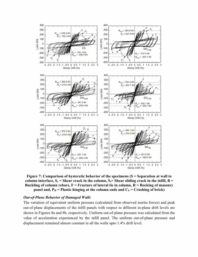
Figure 7: Comparison of hysteretic behavior of the specimens (S = Separation at wall to column interface, Sc = Shear crack in the column, Ss= Shear sliding crack in the infill, B = Buckling of column rebars, F = Fracture of lateral tie in column, R = Rocking of masonry
panel and, PH = Plastic hinging at the column ends and Cb = Crushing of brick)
Out-of-Plane Behavior of Damaged Walls The variation of equivalent uniform pressure (calculated from observed inertia forces) and peak out-of-plane displacements of the infill panels with respect to different in-plane drift levels are shown in Figures 8a and 8b, respectively. Uniform out-of-plane pressure was calculated from the value of acceleration experienced by the infill panel. The uniform out-of-plane pressure and displacement remained almost constant in all the walls upto 1.4% drift level.
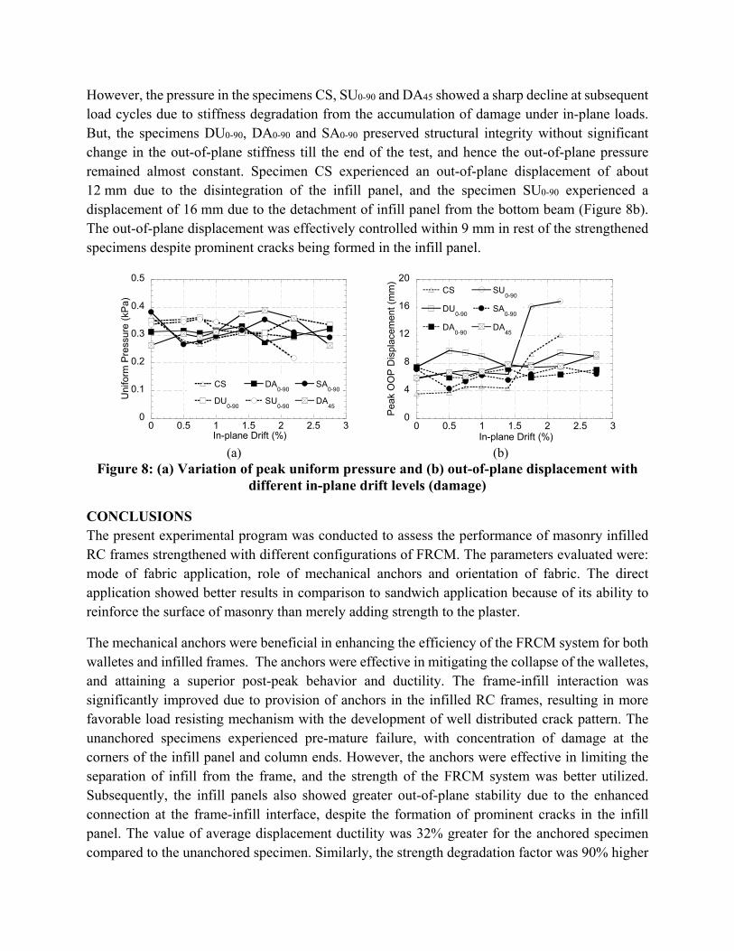
However, the pressure in the specimens CS, SU0-90 and DA45 showed a sharp decline at subsequent load cycles due to stiffness degradation from the accumulation of damage under in-plane loads. But, the specimens DU0-90, DA0-90 and SA0-90 preserved structural integrity without significant change in the out-of-plane stiffness till the end of the test, and hence the out-of-plane pressure remained almost constant. Specimen CS experienced an out-of-plane displacement of about 12 mm due to the disintegration of the infill panel, and the specimen SU0-90 experienced a displacement of 16 mm due to the detachment of infill panel from the bottom beam (Figure 8b). The out-of-plane displacement was effectively controlled within 9 mm in rest of the strengthened specimens despite prominent cracks being formed in the infill panel.
(a) (b) Figure 8: (a) Variation of peak uniform pressure and (b) out-of-plane displacement with
different in-plane drift levels (damage)
CONCLUSIONS The present experimental program was conducted to assess the performance of masonry infilled RC frames strengthened with different configurations of FRCM. The parameters evaluated were: mode of fabric application, role of mechanical anchors and orientation of fabric. The direct application showed better results in comparison to sandwich application because of its ability to reinforce the surface of masonry than merely adding strength to the plaster.
The mechanical anchors were beneficial in enhancing the efficiency of the FRCM system for both walletes and infilled frames. The anchors were effective in mitigating the collapse of the walletes, and attaining a superior post-peak behavior and ductility. The frame-infill interaction was significantly improved due to provision of anchors in the infilled RC frames, resulting in more favorable load resisting mechanism with the development of well distributed crack pattern. The unanchored specimens experienced pre-mature failure, with concentration of damage at the corners of the infill panel and column ends. However, the anchors were effective in limiting the separation of infill from the frame, and the strength of the FRCM system was better utilized. Subsequently, the infill panels also showed greater out-of-plane stability due to the enhanced connection at the frame-infill interface, despite the formation of prominent cracks in the infill panel. The value of average displacement ductility was 32% greater for the anchored specimen compared to the unanchored specimen. Similarly, the strength degradation factor was 90% higher
0
0.1
0.2
0.3
0.4
0.5
0 0.5 1 1.5 2 2.5 3
CS
DU0-90
DA0-90
SU0-90
SA0-90
DA45
Un
iform
Pre
ssur
e (k
Pa)
In-plane Drift (%)
0
4
8
12
16
20
0 0.5 1 1.5 2 2.5 3
CS
DU0-90
DA0-90
SU0-90
SA0-90
DA45
Pea
k O
OP
Dis
pla
cem
ent
(mm
)
In-plane Drift (%)

for the anchored specimen in comparison to the unanchored specimens. Finally, the oblique orientation of fiber strands led to the overstressing of the fabric, and was ineffective in resisting the stresses compared to the orthogonal orientation of the fabric.
ACKNOWLEDGEMENTS The authors would like to acknowledge Saint Gobain Adfors for providing fiber composite materials for the FRCM strengthening of masonry and Saint-Gobain Research India (SGRI) for the collaboration. Any opinions, findings, and conclusions or recommendations expressed in this material are those of the authors and do not necessarily reflect the views of the SGRI.
REFERENCES [1] Tumialan, J.G., Galati, N. and Nanni A (2003): “Fiber-reinforced polymer strengthening of
unreinforced masonry walls subject to out of- plane loads.” ACI Struct. J., 100 (3), 312–329. [2] Silva, P.F., Yu, P. and Nanni, A. (2008): “Monte carlo simulation for validating the in-plane
shear capacity of URM walls strengthened with GFRP grid reinforced polyurea.” J. Compos. Const., 12 (4), 405-415.
[3] Papanicolaou, C.G., Triantafillou, T.C., Papathanasiou, M. and Karlos K (2008): “Textile reinforced mortar (TRM) versus FRP as strengthening material of URM walls: Out-of-plane cyclic loading.” Mater. Struct., 41 (1), 143–157.
[4] Babaeidarabad, S., De Caso, F. and Nanni, A. (2014): “URM walls strengthened with fabric-reinforced cementitious matrix composite subjected to diagonal compression.” J. Compos. Const., 18 (2), 04013045.
[5] Komaraneni, S., Rai, D.C. and Singhal, V. (2011): “Seismic behavior of framed masonry panels with prior damage when subjected to out-of-plane loading.” Earthquake Spectra, 27 (4), 1077-1103.
[6] Singhal V, Rai DC (2013): “Suitability of half-scale burnt clay bricks for shake table tests on masonry walls.” J. Mat. Civ. Eng., 26 (4), 644-657.
[7] Sagar, S. L., Singhal, V., Rai, D. C., and Gudur, P. (2016): “Diagonal shear and out-of-plane flexural strength of fabric-reinforced cementitious matrix – strengthened masonry walletes.” J. Compos. Const., 10.1061/(ASCE)CC.1943-5614.0000796.
[8] AC434. (2013): “Acceptance criteria for masonry and concrete strengthening using fiber- reinforced cementitious matrix (FRCM) composite systems.” ICC Evaluation Service, Whittier, CA.
[9] American Concrete Institute (ACI). (2013). “Design and construction guide of externally bonded FRCM systems for concrete and masonry repair and strengthening.” ACI 549.4R, Farmington Hills, MI.
[10] Singhal, V. and Rai, D. C. (2014): “Role of toothing on in-plane and out-of-plane behavior of confined masonry walls.” J. Struct. Eng., 140 (9), 04014053.
[11] Bureau of Indian Standards (BIS). (2002): “Indian standard criteria for earthquake resistant design of structure, Part 1: General provisions and buildings.” IS 1893, 5th Rev., New Delhi, India.
[12] American Concrete Institute (ACI). (2005): “Acceptance criteria for moment frames based on structural testing and commentary.” ACI 374.1-05, ACI Committee 374, Farmington Hills, MI.