14. diffraction of water waves by breakwatersauthors.library.caltech.edu/48243/1/diffraction of...
TRANSCRIPT
14. Diffraction of Water Waves by Breakwaters
By John H. Carr' and Marshall E. Stelzriede 1
Diffraction is an important factor in the determination of the distribution of wave energy within a harbor, and therefore is of importance in harbor design. Previous investigations in this field have made use of Sommerfeld's solution of the diffraction of waves by a semiinfinite screen to obtain results for semiinfinite breakwaters, and by superposition, approximate results for continuous breakwaters with openings large compared to the wave length. The investigation of this subject by the Hydrodynamics Laboratories of the California Institute of Technology has been guided by the theoretical solutions of Morse and Rubenstein for the diffraction of waves by ribbons and by slits with the two boundary conditions of zero wave function and zero normal gradient. Morse and Rubenstein separate the wave equation in elliptic cylinder coordinates and obtain the total transmission and the angular distribution of the scattered or diffracted waves in terms of Mathieu functions. This method bridges the gap between the method of Rayleigh for very small slits and the approximation based on Sommerfeld's solution, which is applicable for slit widths greater than three or four wave lengths, and is useful for any angle of wave approach.
The difficulties of computation of the required Mathieu functions have been overcome in recent years by the use of modern methods of machine computation. The Institute for Numerical Analysis of the National Bureau of Standards has recently completed the computation of the transmission and distribution of wave energy for openings of one-half, one, two, and three wave lengths, with wave approach angles from 0° to 90° in 15° increments. These data, in the form of polar plots of a dimensionless intensity factor, are compared with experimental measurements conducted to verify the theory, and the two results are found to be in good agreement. The experimental procedure has also been used to investigate a number of breakwater configurations for which theoretical solutions are not obtainable.
1. Introduction
Considered in the most general way, the disturbance level at a point in a harbor is a function of the amount of wave energy entering the harbor and the distribution of the energy within the harbor. Because the aim of the harbor designer is to provide specific regions within the harbor where the wave disturbances will always be less than some maximum, and thus guarantee an optimum level of usability for these regions, the design technique consists of the determination of .disturbance levels in particular places for certain assumed harbor configurations and ocean conditions. The significance of diffraction in connection with the problems of hai-bor layout and design is that both the amount of energy entering the harbor and especially the distribution of wave energy within t he harbor are conditioned by this phenomenon.
The amount of energy entering the harbor is determined largely by the size of the opening and the intensity and direction of the incident wave, but for small openings- less than one wave length in width-diffraction becomes an increasingly important modifying factor.
' California Institute of Technology, Pasadena, Calif.
109

The distribution of wave' energy within a harbor is governed by three factors, diffraction, refraction, and reHection. Of these, diffraction and refraction account for the distribution of what may be called the primary wave disturbances- waves that have not yet reached a boundary and reHected. Secondary, or reflected, wave disturbances are determined by the character and alinement of the harbor boundaries, the distribution of the primary disturbances, and subsequent diffraction and refraction. Because the refraction of water waves is clue to wave-velocity changes corresponding to depth changes, refraction is an important factor in the distribution of wave energy within a harbor only if the topography of the harbor bottom is irregular. Typical harbors on open coasts are characterized by fairly uniform water depths, especially as improved by peri-· pheral bulkheading and dredging, hence in many cases the primary energy distribution, and as a consequence, the secondary distribution for a given set of boundary conditions, may be predicted with sufficient accuracy for engineering application by the consideration of diffraction effects alone.
The Hydraulic Structures Division of the Ilydrodynamics Laboratories, California Institute of Technology, is engaged in a study of the application of the principles of wave behavior to harbor design. This study is sponsored by the Bureau of Yards and Docks of the Department of the Navy. The investigation of water-wave diffraction described herein is one result of this study.
2. Theory
2.1 General
There are two theoretical methods by which the general problem of water-wave diffraction through a breakwater gap may be most directly approached. The first mode of attack, which may be attributed to Penney and Price (1],2 involves a solution by Sommerfeld (2] for diffraction of light waves by a semiinfinite screen , or a half plane. The procedure is extended by superposition to a breakwater with a gap. The resulting solution is reasonably accurate, however, only for gap widths of over two wave lengths.
The second method of approach may be credited largely to Morse and his associates at Massachusetts Institute of Technology [6 to 9]. This analysis, based on elliptic-cylinder coordinates and the associated Mathieu functions, was originally developed for the diffraction of sound and electromagnetic waves. At the Hydraulic Structures Laboratory it has been used with a high degree of success in water-wave diffraction studies, especially because the solution converges most rapidly for gap widths of the order of zero to three wave lengths.
2.2 Penney-Price Method
The principal features of the solution by Penney and Price have been verified experimentally by Putnam and Arthur [3], and by Blue and Johnson (4]. Although this theory did not serve as the primary basis of work done at this laboratory, there is sufficient agreement between it and the Morse-Rubenstein theory within certain areas, so that a brief discussion of it is warranted.
' Fi~~:urea in brackets indicate the literature references on p. 125,
110

The solution is based on the following assumptions: (a) The water is an ideal, incompressible ft uid. (b) Motion of the water is irrotational, and the velocity potential cf> satisfies the Laplace equation,
a2cf> a24> a2¢ -+- + - =0 ax2 ay2 az2
' (1)
where .1·- and y-axcs arc in the plane of the undisturlwcl water surface, and z is the vertieal eoordinate. (c) The wave height is very small. (d ) Tlw pressure at the surface, z=rJ(t), is eonstant. (e)Thc component of the fluid vclocit~' normal to the surface equals the velocity of the surface normal to itself. (f) The velocity of the fluid normal to a fixed boundary surface is zero. (g) The depth of the water is constant.
Using these assumptions, the Laplace equatiou is solved for cf> and an expression set up for the free water surface, by the method of Lamb [5]. These equations arc, respectively,
ct>=Ae-ikct cosh lc(z+h)·Ji'(3.·,y),
ike .k ry=-Ae' ct cosh kh·F(x,y), where
a cJ2F a2Ji' -+-+k2F=O ax2 ay2
'
(2)
(3)
(4)
and where k=27r/ X· c=wavc celerity or velocity· X=wave length; h =water depth: m{d Akc/ g cosh lch:: amplitude.· 'Progressive waves \\·ith straight crest alincment and travelinp; in the positive y-clirection lllay be represented by the following solution of cq 4
Ji'(x,y) =e-iky_ (5)
Consistent with assumption (f), for a rigid barrier extending along the positive x-axis from the origin,
a¢ aF -=-=0, when y=O,x>O. ay ay
(6)
To study the diffraction of waves incident normally on a semiinfinitc rigid breakwater, the 3.·y-planc may be divided into the three regions (shmvn in fig. 1 for a general angle of approach). It can be shown [3] that the modulus and ar!l;ument of F determine, respectively, the amplit.ude and phase of the difTracted wave, hence the problem reduces to that of finding a solution of cq 4, whic·h satisfies the boundary condition of eq 6, and whieh rcduees to eq 5 when x is large and negative.
Penney and Price show that eq 4, 5, and 6 are identical with those :-;atisfied by Sonmwrfeld':-; solution for the diffract.ion of light waves polarized in a plane parallel to the edge of the scmiinfinite screen. In Cartesian coordinates this equation may be written
l+i{ . j" -"-iu' . j"' -"-iu2 } F(.r,y)=--e-'kY e 2 du+e'kY e 2 du•
2 -00 -00
(7)
(8)
111

The signs of u and u' for a given point are determined by which of the three regions, Q, R, or S (fig. 1), contains the point. The form of this Sommerfeld equation is convenient, in that it lends itself to evaluation by means of tabulated values of Fresnel's integrals,
(9)
or by Cornu's spiral. The behavior of the modulus and argument of F over the plane, determined from eq 7, presents a complete picture of the surface configuration in the three regions.
Q
/Direction of / Wave Approach
\
\ \
\
/ /
\ \
/Y I
\ \
\
s Diffraction
FIGURE 1. Regions about semiinfinite breakwater.
Replacing Cartesian by polar coordinates, the Sommerfeld solution may be generalized to the case of waves incident obliquely on a semiinfinite barrier. So far the solution is exact; the specified boundary conditions are satisfied exactly within the limits of certain approximations which were made for convenience. The procedure may be extended to a breakwater with a gap by superposing the solutions for one semiinfinite barrier to the right and one to the left, separated by a gap of width d, and with the origin at the center of the gap.
The resulting compound solution is discussed by Penney and Price for waves of normal incidence. The solution is no longer exact, for the boundary conditions at each barrier are not automatically satisfied by diffraction waves arising from incident waves on the other barrier. For openings of over two wave lengths, aF / ay differs from zero by a relatively small amount at the boundaries, with the accuracy improving with increasing width of opening. For large gaps, therefore, the diffraction picture presented by the behavior of the modulus and argument of F is assumed to be reasonably accurate.
For angles of wave incidence other than normal, the determination of wave heights becomes somewhat more involved. That factor, together with the total unsuitability of the solution for small gaps, prompted the adoption of another theory to serve as the basis for evaluation of experimental data.
112
2.3 Morse-Rubenstein Solution
The unsatisfactory features of the Penney-Price method are largely avoided by the approach outlined by Morse and Rubenstein [6] for diffraction of sound and electromagnetic waves by a slit in an infinite plane. It is an exact solution for small gaps, and possesses the added feature of leading to direct expressions for angular distribution of energy transmitted through the opening, and for the total of such transmitted energy.
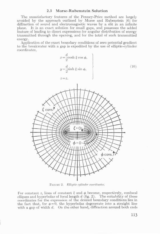
Application of the exact boundary conditions of zero potential gradient to the breakwater with a gap is expedited by the use of ellipt-ic-cylinder coordinates,
( I 0)
Z=Z.
Fwurn; 2. Elliptic cylinder coordinates.
For constant z, lines of constant ~ and </> become, respectively, confocal ellipses and hyperbolas of focal length d (fig. 2). The suitability of these coordinates for the expression of the desired boundary conditions lies in the fact that, for tJ> = 0, the hyperbolas degenerate into a straight line with a gap of width d. On the other hand, diffraction around both ends
113
oi a barrier of finite length, the reciprocal case to the breakwater with a gap, could be investigated by using the degenerate ellipse, corresponding to ~=0.
The three-dimensional wave equation is, in Cartesian coordinates,
a2o/ azo/ a2o/ 1 azo/ -+-+- =--, ax2 ay2 az2 c2 at~ ( U )
where cis <Lgain the velority of wave propagation. Substituting the new coordinates into CCJ 11 puts the wave efjuation in the ellypt ir-rylinder forn1
( 12)
It is desirable to find solutions of the wave equation, which, in addition to possessing zero gradient at the two slit walls, di sappear at infinity and remain finite in the gap.
The variables in eq 12 may now be separated in the standard manner, by assuming a product solution of the form
o/ =G(~)Il(¢)Z(z) e- 2,-ivt, (13)
v being the wave frequency. Neglecting time and the z-coordinate, since the propagation vector is taken in the xy-plane, the following differential efjuations result
d2If -+ (b- s eo:-:;~ A-)lf = 0 d¢2 ~ '
d2G -+(s cosh2 1:-b)G=O d~2 <; '
( 14 )
(15)
where s= (1rdjA.) 2, and b is a separation constant. Equations 14 and 15 are commonly known, respectively, as Mathieu's equation and Mathieu's modified equation, the second being derivable from the first by substituting ¢=i~.
Solutions of these equations, and linear combinations of such solutions are, of course, solutions of the wave equation from which eq 14 and 15 arise. Using a countably infinite number of values of the charac-teristic constant b results in an infinite number of solutions of the differential equations, not all of which arc periodic. In particular, it is the solutions, or Mathieu functions, of periods 1r and 21r, which arc of present interest.
Each equation possesses even and odd solutions, which , in the case of the. angular functions, or solutions of eq 14, assume the form of Fourier senes
"" Ser(s,¢) = L_'Dek cos kcp, ( 16a) k=O
"' Sor(s,cjJ)=L._'Do"sin kcp. (l6b ) k=ll
That these functions form an orthogonal set can be easily shown. Even and odd solutions of the first kind of the modified equation are designated
114

Jer(s,~) and Jor(s,~;, ar:d these of the second kind are Ner(s,~) and Nor(s,O. As their de~ignations indicate, these radial Mathieu functions are normally expressed in terms of Bessel'~ functions of the first and second kinds. Computable factor~ of proportionality or joining factors, however, relate the radial function s Lo each other and to the angular functions.
The ;; ubscripts r in cq 16a and 16b arc index numbers 0, 1, 2, 3, ... corresponding to increasing characteristic values of the parameter b that yield the desired periodic functions and identify the order of the solution. In practice, for a gate width of three wave lengths or less, convergence of the final equations is such thaL it is necessary to consider values of r up to a maximum of about five or six. The primed summation signs indicate that for even values of r, only even values of k are included in the summation, and for odd r only odd values of k are summed.
The l\fathieu coefficients, Dek and Dok, may be determined by sub:,; tituting eq 16a or 16b into the l\IaLhicu eq 14, using the series representation for trigonometric functions, a1:cl equating coefficients of like powers of cp to zero. The cocfficienLs are then seen to satisfy certain recursion relationships that may be represented b.v continued fractions. The value of such fractions may be computed, provided the first coefficient is known. This first coeffici-ent, where k = 0 or 1, as the case might be, is effectively established by choosing
Sem(s,O) = 1, (17a)
d dq, [Se,. (s,cp) ]q,=o = 0, (17b)
and So,.(s,O) =0, (18~L)
d dcp [Som(s,cp) ]q,=O = 1. (18b)
Normalizing in Lhis nmnncr also insures the vanishing of the wave-funcLion gradient at the boundaries. RLratton, et al. [9] published a very limited Lable of even and ode! coefficients with their associated characteristic values. The Institute for K umerical Analysis of the National Bureau of SLandards is publishing an extensive table of coefficients, characteristic \'alues and joining factors. This publicaLion [101 may well serve as a handbook on l\1athieu funcLions, as, in addition to the tables and an extensive hibliograph~', the introduction cont:1ins a summary of all important relations involYing Lhe functions.
Mor::;e [81 dcmonsLrates that Lhc addition formula expressing LlH' <'xpansion of a plane, or in Lhc ca~e of water straight-cre~ted, wave in tern:~ of l\fathicu fUI:ctions is, exclusiYe of tht time factor,
where N,, and N,n' arc normalization factors, and u is the angle of inridcnee of the wa\'0" with the breakwater. The diffracted wavf' beyond the
115
rip:id breakwater with a gap is expressed by the equation
·m-1
if;= V 81r"£~N sin l'mi'""Sem (s,u) S em(s,</>)- [Jem(s,~) +iNem(s,m. (20) m m
Here I'm is the phase angle of the partial wave, and ctn I'm= (Nem(s,O)) /(J .m(s,O)) is identical in value to the joining factors fe,r tabulated by t.he Institute for Numerical Analysis. The quantity in brackets bears the same relationship to the radial functions of the first and second kinds as Hankel functions bear to the Bessel functions, and represent diverging cylindrical waves which disappear at infinity but remain finite in the region of the gap. It may be shown that the gradient of the wave function of eq 20 is zero at the slit boundary, and t.hat if; and its gradient are continuous in the slit opening.
The modulus of eq 20 represents t he amplitude of the diffracted wave. It may be shown 3 that at sufficient distance R from the center of the opening, the normal expression for the energy flux carried by a straightcrested wave may be applied with ample accuracy to a diverging circular wave. As a matter of fact, at points where the radius of curvature of the wave crest is as little as about three wave lengths, the error introduced by using this relationship is negligible. It is apparent, therefore, that the ratio of energy intensity at a point in the harbor to that in the open sea is h~.<1>/h~, where hp,</> is the wave height at the point, and h; is the incident wave height. Or, if the incident intensity is taken as unity, t he intensity at a point is just h't,<!> ·
If the asymptotic forms of the radial functions
Jem(s,~)-+ /I_cos a, p-+oo\J Cp
(21)
where a=[cp-(2m
4+1)7r], and p=cosh ~'be introduced into cq 20,
and the modulus squared, this expression results
Ip,</>= h!,</>= -s;_ L NlN sin I' m sin 'YnSem(s,u)Sen(s,u) V Sp m.n m n
(22)
Wl~ en R is sufficiently large,
d 2R x= 2p cos <t>=R cos</>, or p=a· (23)
Tten the intensity of the diffracted wave at (R,</> ) resulting when a plane
s Proof that the plane·wave expression is valid for diverging waves of sufficiently large radius of curvature was communicated to the Hydraulic Structures J. .. aboratory by L. I. R-chiff, and is based on the rapidity of convergence of the Beseel'e functions of the first and second kinds for a given radius of curvature of the wave crest.
116
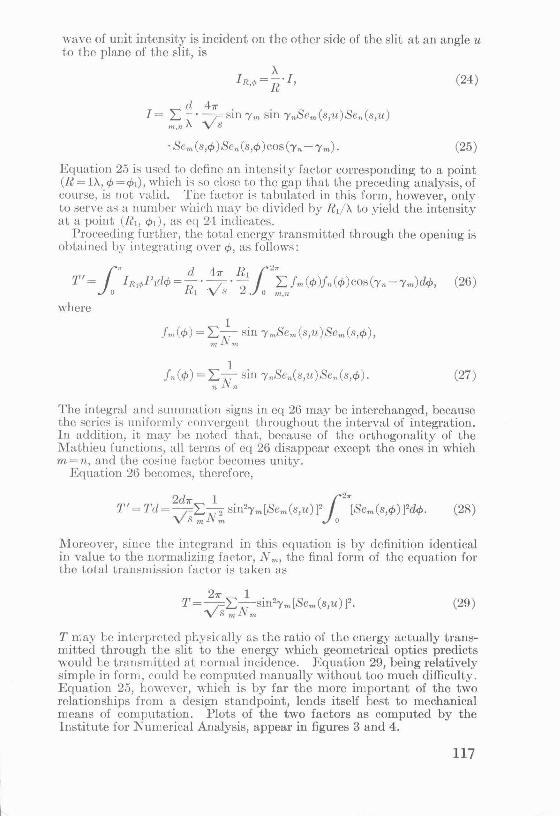
wave of unit intensity is incident on the other side of the slit at an angle u to the plane of the slit, is
A 1R."'= n·I,
I= I:~· _4~- sin 'Ym sin 'YnSem(s,u)Sen(s,u) m,n A V S
(24)
(25)
Equation 25 is used to define an intensity factor corresponding to a point (R = IA, tj> = t:/>1), which i:; so close to the gap that the preceding analysis, of course, is not valid. Tnc factor is tabulated in this form, however, only to serve as a number which may be divided by R1/ A to yield the intensity at a point (R1, t:/>1), as cq 2-l indicates.
Proeeecling further, the total energy transmitted through the opening is obtained by integrating over tj>, as follows:
(26)
where
fn(t:/>) = LNl sin 'YnSen(s,u)Sen(s,tj>). " n
(27)
The integral and summation signs in eq 26 may be interchanged, because the series is uniformly convergent throughout the interval of integration. In addition, it may be noted that, because of the orthogonality of the Mathieu functions, all terms of eq 26 disappear except the ones in which m = n, and the cosine factor becomes unity.
Equation 26 becomes, therefore,
, 2d11'" 1 . s c ) 12 .. s c ) T = Td=- ~.i..--2 Sll12'Ym[ em s,u F [ e,. s,tj> ]2dtj>. ·vs,N,. o
(28)
Moreover, since the integrand in this equation is by definition identical in value to the normalizing factor, N m, the final form of the equation for the total transmission factor is taken as
(29)
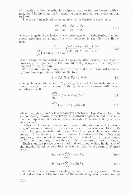
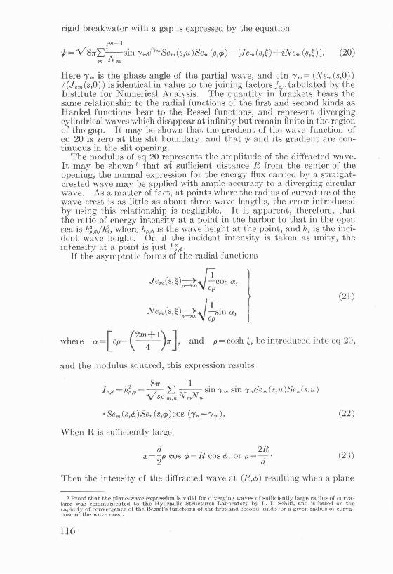
T rr.ay be interpreted physically ss the ratio of the energy actually transmitted through the slit to the energy which geometrical optics predicts would be tram:mitted at normal incidence. Equation 29, being relatively simple in form, could be computed manually without too much difficulty. Equation 25, however, which is by far the more important of the two relationships from a design standpoint, lends itself best to mechanical means of computation. Plots of the two factors as computed by the Institute for Numerical Analysis, appear in figures 3 and 4.
117

V?J ?
_Q /
0 .25
D-----"!-L-1 !
OPENING • I WAVE LENGTH
I OPENING • 2 WAVE LENGTHS OPENING • 3 WAVE LENGTHS
I .' J« U~< J ·: :3. l'o/m· fllot" of inlensily factor,
(.1!" .p,2 u I r<.<~>= (h)2x>:.
(VertiC'al face straight breakwaters.)
2.4 Comparison
While the Mor::>e-Rubenstein solution appears to be of most direct value in harbor design , it shou ld be pointed out that the Penney-Price solution, too, pos;esses certain valuable qualities. The wave crest alinement and phase relationships, for example, are more readily ascertained by the latter method, except for the small opening::>. For very large gap ·widths, say of the order of seven or eight wave length s, the boundary cor.clition of the Penney-Price solution approaches the desired value rather well, whereas the Mathieu functions converge much more slowly for large openings. For that reason, i.t may be more convenient for such 1:1!'ge widths to determine the energy intensities by means of the PenneyPrice approach.
It is interesti:-~g to note that there is a great deal of agreement between results of the two methods in their common domain. It has been found,
118
for example, that an intensity plot based on wave heights tabulated by Penney and Price for an opening of 2.5 f.. shows a form strikingly similar in relative proportions to one for a 2/.. opening based on the .Morse-Rubenstein solution.
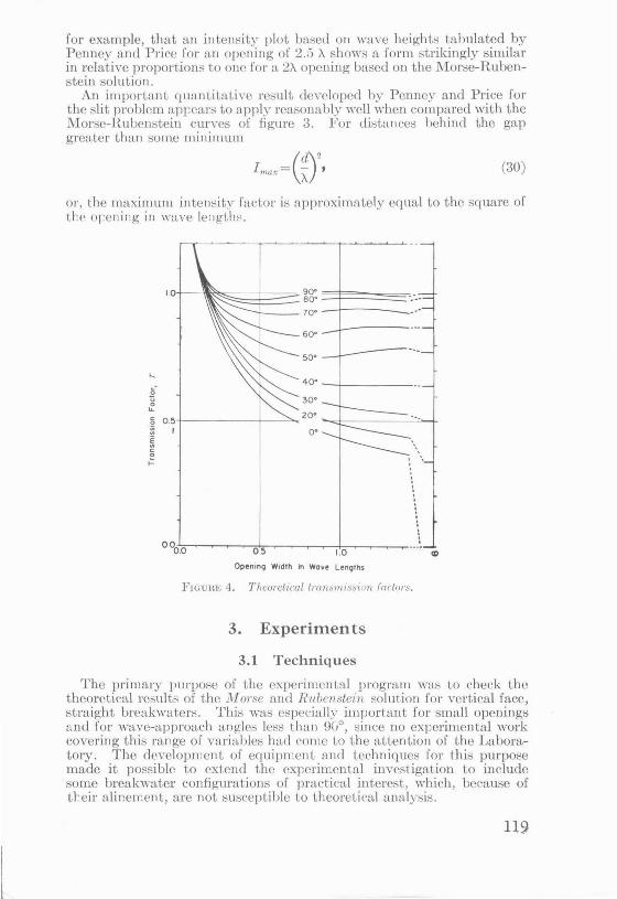
An important quantitative result developed by Penney and Price for the slit problem appears to apply reasonably well when compared with the Marse-Rubenstein curves of figure 3. For distances behind the gap greater than some minimum
(d)2 lmax= ~ ' (30)
or, the maximum intensity factor is approximately equal to the square of the orening in wave lcng"t.h:- .
....
~ 0 u. c 0.5 0
:::
I ;:.
30"
T---------,_--~20"--±---------~-+ o•
'
0
Openmq Width m Wave LenQths
FIGURE 4. Theorelicallnm~mission foetor~ .
3. Experiments
3.1 Techniques
The primary purpose of the experimental program was to check the theoretical results of the "AI 01'se and Rubenstein solution for vertical face, straight breakwaters. This was especially important for small openings and for wave-approach angles less than 9(/, since no experimental work covering this range of variables had come to the attention of the Laboratory. The development of equipment and techniques for this purpose made it possible to extend the experimental investigation to include some breakwater configurations of practical interest, which, because of tteir alinement, are not susceptible to theoretical analyfolis.

'The experiments were conducted in an L-shaped basin (fig. 5), 20 feet wide by 60 feet long, with an offset portion 12 by 24 feet at the shallow end. The water depth at one end of the basin was made 12 inches to accommodate one of the standard laboratory pneumatic wave generators, with the bottom rising from this depth at a slope of 1 in 40 to a line where the depth is 3 inches. The remainder of the basin bas a uniform depth of 3 inches. The breakwaters and "harbor" were located in the region of uniform water depth , thus clin1inaLing refraction phenomena f10m the investigation. Pe:1 gravel beaches around the periphery of the harbor effectively prevented reflection from the basin walls. Different angles of
FIGURE 5. Basin for experimental measurements.
wave approach were obtained by rotating the breakwater, the wave machine remaining fixed. Tl~e offset portion of the basin provided space for a clamping beach to prevent the reentry of waves reflected from the breakwater into the region near the breakwater opening, thus simulating a basin of infinite extent. For the cases where ihe breakwater was alined at 60° and 90° to the direction of wave approach, waves reflected from the breakwater were not intercepted by this side beach, but t.raveled the length of the basin, reflected from the wave machine and so could interfere with the incident wave train. Difficulties of this kind were prevented by providing sufficient distance from wave generator to breakwater so that measurements could be obtained before waves reflected from the breakwater reached the wave generator.
Incident wave height was measured in deep water, near the wave machine, to insure freedom from obscuring reflections . The data obtained was corrected to represent wave heights incident at the breakwater opening. Calculations based on the effect of shoaling indicated that the deep-water values should be reduced by 8 percent, but direct measurement of the change in incident wave height gave a value of 25 percent. The additional height reduction is assumed to be a fluid friction phenomenon.
The distribution of transmitted wave energy was obtained by waveheight measurements at 4° intervals on a semicirc!c of radius 5.76 wave
120
lengths centered ou the opening. The intensity factor, I R,</> m each direction cf> can then be expressed as:
where
[ = (hR,</>) 2 • !!:_= (hR,</>) 2, R,</> (h;)2 A 5.76 (h;)2
hR,<t> =wave height measured at c/>,R, inside the breakwater,
h; =wave height incident at the breakwater,
H, =radius of measuring circle, A =wave length.
The total transmission factor, T, is computed by a summation process
1 <hR,</>) 2Rdcf> T= '
h?d
where dis the gap width in the same units as R. 'Vave heights were measmed by means of sixteen channels of electrical
conductivity cells. Each cell consists of a pair of wire electrodes supported and spaced one-half inch apart by an insulating block at one end. The electrodes are immersed to a mean submergence of 1 inch, and a constant voltage is applied across the cell. The amount of current conducted by the cell is a linear function of the submergence, hence of wave height. The current signal from each cell corresponding to t he wave motion past each cell is recorded on a galvanometer osci llograph.
3.2 Results
A comparison of theoretical with experimentally determined energy transmission for vertical face straight breakwaters is shown in figure 6. The theoretical solutious indicate that for projected widths of openings in the direction of wave approach greater than one-half wave length, the effc(·t of diffraction on energy t ransmission is minor, but for smaller openings, the energy transfer is larger t han would be expected from geometrical considerations. The experimental data are in fai rly good agreement with the theoretical values with respect to these general conclusions, although the measured values are about 20 percent lower than theoretical. Because wave energy is proportional to the square of t he wave height , the difference between theory and experiment on a wave-height basiswhich is the measured quantity- is but lO percent in most cases. These results are considered sufficient evidence of the validity of the theoretical approach, at least for engineering applications.
The most important application of diffraction considerations is in the analysis of wave-energy (or height) distribution in the lee of the breakwater gap. Figures 7, 8, and 9 present some results of experimental distribution measurements for three breakwater configurations: (1) straight arms in line with each other, (2) st raight arms inclined symmetrically "ith respect to all axis consisting of the perpendicular bisector of the line of the opening, (3) straight arms at right angles to each other, the seaward arm parallel, and the leeward arm perpendicular to the incident wave crests. Three degrees of sheltering of the gap by the sea-
121

ward arm \\'ere studied, eorrospm:cling to projeeted openings in tho direct ion of wave advance of l / V2 ancl zero gap widths, and a seaward arm overlap of l / V2 gap widths.
1.2,.-,,----- ----r------,-------,,--- -----,- ----vy ~-----,
I Of--~,:.._:...,-----+-----c-=-~~-=--4-'-'-fJ'-"p'-'_ :=--~----~-d---,_,.-,_oc_=--=--=-~-~-~-=1=-~--- - - -~-- 90• ·~~\\ //
L __ ._\:~::;·,~::.·~-::~--:O.--.,_.--[::_:::J=-6=_ fJ=. :=_=_=--=·=--=--=--i-=-=-=-=-=-=-=-=-1--"'~,~~~-.,..7-- - so-\'-.\ '.,_ 90• ~
0.8 /
.: 0
0 .6 u 0
LL
~ Expenmentol
-~9. .. Theoretical
---~ 0 a. E
-------7- ~ 30"
I - ~-
I I
~ ----1
1 --->-- 15·
' ' ' ' ' ',, ' o.oo~o:-----~o"=.5 _____ -,~-Lo=--------'~_"'5-----2L.o_/"_"""_"-"'...::."-'"~-~ ....... o·
Opening W1dths in Wove Lengths
FIGURE (j_ Theoretical and experimental transmission .facto1·s. (Vertical face straip:ht breakwaters.)
The experimental data for straight breakwater alinements, some of which are shown in figure 7, may be compared with the theoretical data of figure 3. The agreement between experiment a nd theory, while not exact, is reasonably close, ancl supporls the important general conclusions of the theory. In particular, the experimental data verify that the maximum value of the intensity factor i:-; proportional to the square of the gap width , and that the effect of reducing the gap width is to distribute the wave energy more uniformly in the region behind the breakwater.
Figures 8 and 9 present experimental data for the wave-energy distribution in the Icc of some breakwater configurations that cannot be analyzed by the theoretical approach.
The data of figure 8 show the energy distribution resulting from normal wave approach for an imporLant class of breakwater a linements- symmetrical arms converging seawatd, or so-called "wave traps." The data show that, as the included angle between the breakwater arms is reduced from 180° (straight breakwater) to 9v0
, there is virtually no change in the energy distribution. This result is in agreement with the observations of
122

Scale .· fO I
Two wave le,lgth openings
_0_ One wave length openings
j_ One-half wave length openings
.rl ___d__
FIGURE 7. Polar plots of energy distribution. (Vertical face straight breakwaters.)
"'-/ 90~!
Scale 1.0 I
Two wove length openings
J\ FIGURE 8. Polar plots of energy distribution;
(Vertical face symmetrically inclined breakwaters.)
123
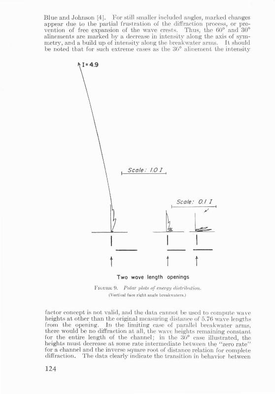
Blue and Johnson [4]. For still smaller included angles, marked changes appear due to the partial frustration of the diffraction process, or prevention of free expansion of the wave crests. Thus, the 60° and 30° alinements are marked by a decrease in intensity along the axis of symmetry, and a build up of inten sit~r along the breakwater arms. It should be noted that for such extreme cases as the 30° alinement the intensity
1 Scale : 1.0 I ,
Scale: 0.1 I
t t t Two wove length openings
li'1GUHE 9. Polar plots of energy distribution. (Vertical face right angle breakwaters.)
factor concept is not valid, and the data cannot be used to comput.e wave heights at other than the original measuring distance of 5.76 wave lengths from the opening. In the limiting case of parallel breakwater arms, there would be no diffraction at all , the wave heights remaining constant for the entire length of the channel; in the 30° case illustrated, the heights must decrease at some rate intermediate between the "zew rate" for a channel and the inverse square root of distance relation for complete diffraction. The data clearly indicate the transition in behavior between
124

60° and 30° enclosed angles, and so points out an important factor to be considered in the design of harbors with converging breakwaters.
The data of figure 9 are included as a purely experimental evaluation of types of energy distribution that may occur for typical asymmetrical breakwater alinements. The origin of the polar plots for these cases is not the center of the breakwater opening as in the other figures, but is the terminus of the breakwater arm oriented parallel to the incident wave crests.
The case in which the seaward arm does not shelter the opening may be regarded as a half-model of a straight breakwater with a gap width of 2V2>-. The resulting intensity diagram, with allowance for the skewness resulting from the unsymmetrical locus of the plot, compares in general shape (although somewhat deficient in magnitude) with the corresponding data of figure 3 for a 3>. opening.
The intensity diagram for the case in which the seaward leg just shelters the gap is similar in shape and of the same order of magnitude as those for the straight breakwater with 0° wave approach. This observation is in agreement with the behavior observed for some of the symmetrically inclined breakwater alinements, that the diffraction process is more sensitive to the angle of wave approach with respect to the alinement of the opening than to the alinement of the breakwater arms which define the opening.
The diagram for the case in which the seaward arm overlaps the leeward arm not only shows the remarkable increase in sheltering obtained with such alinements, but also indicates a shift in direction of ihe maximum disturbance. The latter effect is easily explained: The wave crests after diffraction around the terminus of the seaward arm of the breakwater approach the leeward leg at nearly 90°, and the resulting intensity distribution is as would be expected after diffraction around the leeward tenninus.
4. References
[11 Penney, W. G. and Price, A. T., Diffraction of sea waves by breakwaters, Directorate of Miscellaneous :weapons Development History No. 26- Artificial Harbors, Sec. 3D, 1944.
[2] Sommerfeld, A., Math. Annalen. Bd. 47, p. 317 (1896). [3] Putnam,~ :J. A. and Arthur, R. S., Diffraction of water waves by breakwaters
Transactions, American Geophysical Union 29, No.4, Aug. 1948. [41 Blue, F. L. and Johnson, J. W., Diffraction of waves passing through a breakwater
gap, Transnctions American Geophysical Union 30, No.5, Oct. 1949. [5] Lamb, H., Hydrodynamics, Sixth Edition, Dover Publications, 1945. [6] Morse, P. M. and Rubenstein, P. J., The diffraction of waves by ribbons and by
slits, Physical Review 54, pp. 895-8, Dec. 1, 1938. [71 Stratton, J. A., Spheroidal functions, Proceedings of National Academy of Sci
ences 21, pp. 51-6, 1935. [8] Morse, P. M., Addition formulae for spheroidal functions, Proceeding of National
Academy of Sciences 21, pp. 56-62, 1935. [9] Stratton, Morse, Chu, Hutner, Elliptic cylinder and spheroidal wave functions,
N. Y. Wiley, 1941. 10] Blanch, G., Introduction to tables of Mathieu Functions, Institute for Numerical
Analysis, National Bureau of Standards. (Now being published-contains extensive bibliography on Mathieu functions.)
125