diffraction of ocean waves around a hollow cylindrical...
TRANSCRIPT

Wave Motion 46 (2009) 78–88
Contents lists available at ScienceDirect
Wave Motion
journal homepage: www.elsevier .com/locate /wavemoti
Diffraction of ocean waves around a hollow cylindrical shell structure
Song-Ping Zhu *, Lewis MitchellSchool of Mathematics and Applied Statistics, University of Wollongong, Northfield Avenue, Wollongong, NSW 2522, Australia
a r t i c l e i n f o
Article history:Received 21 January 2008Received in revised form 29 August 2008Accepted 4 September 2008Available online 12 September 2008
Keywords:Renewable energyOscillating Water ColumnOcean wavesLinear wave theoryWave diffraction
0165-2125/$ - see front matter � 2008 Elsevier B.Vdoi:10.1016/j.wavemoti.2008.09.001
* Corresponding author.E-mail address: [email protected] (S.-P. Zhu).
a b s t r a c t
In recent years, there has been renewed interest in problems of diffraction and radiation ofocean waves around structures, in relation to ‘‘green” power generation by OscillatingWater Column (OWC) devices. In this paper, we present a first-order analytical solutionfor the diffraction of ocean waves around a hollow cylindrical shell structure suspendedin an ocean of finite depth. By revisiting work done by Garrett (1970) on the problem ofa bottomless harbor, but adopting a different and more direct method, we obtain the solu-tion for the diffracted wave potential.
Using the new approach, we analyze the dependence of the solution upon variousparameters, as well as the rate of convergence of the series solution. Apart from some prob-lems we observed with matching the boundary condition at the edge of the cylinder, wefind good agreement with Garrett’s results. Furthermore, we analyze the accuracy of thesolution as a function of cylinder submergence. Finally, we briefly discuss the extensionof the method to the related problem of radiation of surface waves by an oscillating surfacepressure inside a hollow suspended cylindrical shell structure.
The results presented in this paper show that even a simple hollow cylinder, which onlycaptures the most essential feature of an OWC, can produce very complicated patterns ofdiffracted waves. This clearly demonstrates the complexity associated with using OWCdevices to convert ocean wave energy to electricity and the necessity of further fundamen-tal research needed in this area before we can realistically adopt this new technology toefficiently produce renewable energy in practice.
� 2008 Elsevier B.V. All rights reserved.
1. Introduction
Utilizing renewable energy resources has become an important field of study with regards to combatting climate change.Recent studies show that Oscillating Water Column (OWC) devices are an attractive approach to convert the power of oceansurface waves to electrical energy or to directly use the converted mechanical energy to desalinate water [1]. Such deviceswork on the principle that a plane wave field that is incident upon a hollow vertical chamber will force air to oscillate insidethe chamber, which can be used to drive a specially designed turbine, that rotates in one direction while the air flow thatdrives its rotation alternates its direction. For example, Oceanlinx Limited Australia has already developed a prototype basedon the concept of OWC. Fig. 1 displays this prototype, which is currently installed at Port Kembla, NSW, Australia and hassuccessfully converted ocean wave energy into electricity in a number of test runs.
Two of the problems that arise when trying to design an OWC plant to efficiently extract the maximum energy from anincoming wave field are:
1. How to design the shape of the OWC chamber to extract the largest possible oscillating pressure inside the device.2. Where to position the device in the ocean to capture waves as large as possible.
. All rights reserved.
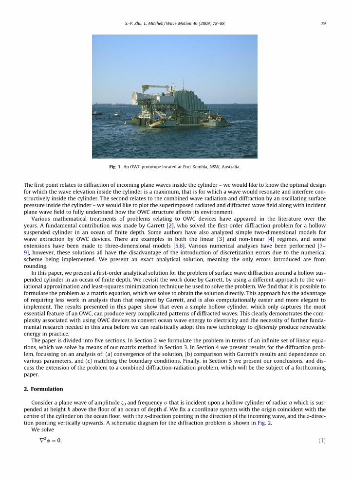
Fig. 1. An OWC prototype located at Port Kembla, NSW, Australia.
S.-P. Zhu, L. Mitchell / Wave Motion 46 (2009) 78–88 79
The first point relates to diffraction of incoming plane waves inside the cylinder – we would like to know the optimal designfor which the wave elevation inside the cylinder is a maximum, that is for which a wave would resonate and interfere con-structively inside the cylinder. The second relates to the combined wave radiation and diffraction by an oscillating surfacepressure inside the cylinder – we would like to plot the superimposed radiated and diffracted wave field along with incidentplane wave field to fully understand how the OWC structure affects its environment.
Various mathematical treatments of problems relating to OWC devices have appeared in the literature over theyears. A fundamental contribution was made by Garrett [2], who solved the first-order diffraction problem for a hollowsuspended cylinder in an ocean of finite depth. Some authors have also analyzed simple two-dimensional models forwave extraction by OWC devices. There are examples in both the linear [3] and non-linear [4] regimes, and someextensions have been made to three-dimensional models [5,6]. Various numerical analyses have been performed [7–9], however, these solutions all have the disadvantage of the introduction of discretization errors due to the numericalscheme being implemented. We present an exact analytical solution, meaning the only errors introduced are fromrounding.
In this paper, we present a first-order analytical solution for the problem of surface wave diffraction around a hollow sus-pended cylinder in an ocean of finite depth. We revisit the work done by Garrett, by using a different approach to the var-iational approximation and least-squares minimization technique he used to solve the problem. We find that it is possible toformulate the problem as a matrix equation, which we solve to obtain the solution directly. This approach has the advantageof requiring less work in analysis than that required by Garrett, and is also computationally easier and more elegant toimplement. The results presented in this paper show that even a simple hollow cylinder, which only captures the mostessential feature of an OWC, can produce very complicated patterns of diffracted waves. This clearly demonstrates the com-plexity associated with using OWC devices to convert ocean wave energy to electricity and the necessity of further funda-mental research needed in this area before we can realistically adopt this new technology to efficiently produce renewableenergy in practice.
The paper is divided into five sections. In Section 2 we formulate the problem in terms of an infinite set of linear equa-tions, which we solve by means of our matrix method in Section 3. In Section 4 we present results for the diffraction prob-lem, focussing on an analysis of: (a) convergence of the solution, (b) comparison with Garrett’s results and dependence onvarious parameters, and (c) matching the boundary conditions. Finally, in Section 5 we present our conclusions, and dis-cuss the extension of the problem to a combined diffraction-radiation problem, which will be the subject of a forthcomingpaper.
2. Formulation
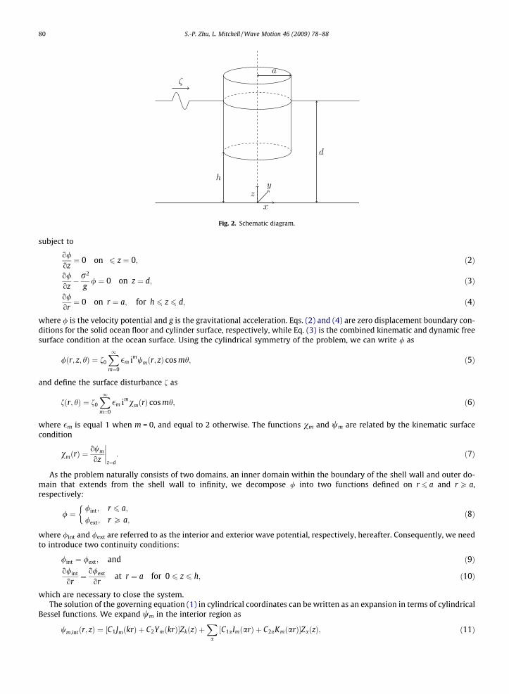
Consider a plane wave of amplitude f0 and frequency r that is incident upon a hollow cylinder of radius a which is sus-pended at height h above the floor of an ocean of depth d. We fix a coordinate system with the origin coincident with thecentre of the cylinder on the ocean floor, with the x-direction pointing in the direction of the incoming wave, and the z-direc-tion pointing vertically upwards. A schematic diagram for the diffraction problem is shown in Fig. 2.
We solve
r2/ ¼ 0; ð1Þ
ζ
x
zy
a
h
d
Fig. 2. Schematic diagram.
80 S.-P. Zhu, L. Mitchell / Wave Motion 46 (2009) 78–88
subject to
o/oz¼ 0 on 6 z ¼ 0; ð2Þ
o/oz� r2
g/ ¼ 0 on z ¼ d; ð3Þ
o/or¼ 0 on r ¼ a; for h 6 z 6 d; ð4Þ
where / is the velocity potential and g is the gravitational acceleration. Eqs. (2) and (4) are zero displacement boundary con-ditions for the solid ocean floor and cylinder surface, respectively, while Eq. (3) is the combined kinematic and dynamic freesurface condition at the ocean surface. Using the cylindrical symmetry of the problem, we can write / as
/ðr; z; hÞ ¼ f0
X1m¼0
�m imwmðr; zÞ cos mh; ð5Þ
and define the surface disturbance f as
fðr; hÞ ¼ f0
X1m¼0
�m imvmðrÞ cos mh; ð6Þ
where �m is equal 1 when m = 0, and equal to 2 otherwise. The functions vm and wm are related by the kinematic surfacecondition
vmðrÞ ¼owm
oz
����z¼d
: ð7Þ
As the problem naturally consists of two domains, an inner domain within the boundary of the shell wall and outer do-main that extends from the shell wall to infinity, we decompose / into two functions defined on r 6 a and r P a,respectively:
/ ¼/int; r 6 a;
/ext; r P a;
�ð8Þ
where /int and /ext are referred to as the interior and exterior wave potential, respectively, hereafter. Consequently, we needto introduce two continuity conditions:
/int ¼ /ext; and ð9Þo/int
or¼ o/ext
orat r ¼ a for 0 6 z 6 h; ð10Þ
which are necessary to close the system.The solution of the governing equation (1) in cylindrical coordinates can be written as an expansion in terms of cylindrical
Bessel functions. We expand wm in the interior region as
wm;intðr; zÞ ¼ C1JmðkrÞ þ C2YmðkrÞ½ �ZkðzÞ þX
aC1aImðarÞ þ C2aKmðarÞ½ �ZaðzÞ; ð11Þ

S.-P. Zhu, L. Mitchell / Wave Motion 46 (2009) 78–88 81
where C1, C2, C1a and C2a are constants to be determined through the satisfaction of the boundary conditions. The exteriorfunction wm,ext has exactly the same form of expansion, except the coefficients in front of each of the eigenfunctions are dif-ferent. The wave numbers k and a are determined from the dispersion relations
x2 � gk tanh kd ¼ 0; and ð12Þx2 þ ag tan ad ¼ 0; ð13Þ
respectively. Dispersion relation (12) has a single pair of real roots ±k corresponding to the propagating wave, while dis-persion relation (13) has an infinite set of real roots ±an, corresponding to the non-propagating evanescent modes of thesolution. It is the existence of this infinite set of evanescent modes which provides the theoretical basis for the seriessolution we will employ below, and accounts for the summation over a in (11). Numerically, the terms generated bythe wave numbers from dispersion relation (13) are small and are associated with localized waves near the cylinderonly, however, they must be included for completeness of the solution. Mathematically, the dispersion relations (12)and (13) are a result of satisfying the free-surface boundary condition (3), while physically they present a most uniquefeature of water waves, i.e., wave velocity is dependent on wave number and thus waves of different wave numbers will‘‘disperse” or spread out over time.
The functions Zk and Za in (11) are the associated eigenfunctions in the vertical direction, corresponding to each mode kand a, respectively. They are of the form
ZkðzÞ ¼ N�1
2k cosh kz; ð14Þ
ZaðzÞ ¼ N�1
2a cos az; ð15Þ
where
Nk ¼12
1þ sinh 2kd2kd
� �;
Na ¼12
1þ sin 2ad2ad
� �:
Since {Zk,Za} form an orthonormal set in [0,d] [10], we may expand the function owmor over the entire interval [0,d] as
owm
or
����r¼a
¼X
aFmaZaðzÞ; ð16Þ
where
Fma ¼1d
Z h
0fmðzÞZaðzÞdz; ð17Þ
fmðzÞ ¼owm
or; at r ¼ a for 0 6 z < h: ð18Þ
We thus have expansions for the interior and exterior functions
wm;intðr; zÞ ¼X
aFma
ImðarÞaI0mðaaÞ
ZaðzÞ ð19Þ
and
wm;extðr; zÞ ¼ JmðkrÞ � J0mðkaÞH0mðkaÞ
HmðkrÞ� �
ZkðzÞZ0kðdÞ
þX
aFma
KmðarÞaK 0mðaaÞ
ZaðzÞ; ð20Þ
respectively.
3. Solution
The constants Fma are obtained by imposing the continuity condition (9), utilising the orthogonality of the eigenfunctionsZa and Zb. This yields a set of infinitely many linear equations for Fma as
FmCb ¼X
aEbaFma; ð21Þ
82 S.-P. Zhu, L. Mitchell / Wave Motion 46 (2009) 78–88
where Z h
Cb ¼1d 0
ZkðzÞZbðzÞdz; ð22Þ
Dba ¼1d
Z h
0ZaðzÞZbðzÞdz; ð23Þ
Eba ¼ ðRa � 1ÞDba þ dba; ð24Þ
Fm ¼ 2i pka2H0mðkaÞZ0kðdÞh i�1
; ð25Þ
Ra ¼ a2a2I0mðaaÞK 0mðaaÞ� ��1
: ð26Þ
The integrals in (22) and (23) can be evaluated exactly, and the solution of (21) for Fma gives the complete solution to theproblem.
From here on we use a simpler and more direct method to solve (21) for the unknown constants Fma than that employedby Garrett. Garrett’s approach is to further manipulate (21) in order to separate it into real and imaginary parts. He then usesa least-squares minimization technique on a new function Ua derived from (21) to obtain a linear equation which my besolved numerically for any number of eigenvalues a. As the exact solution is presented as an infinite summation over theroots a, Garrett truncates the summation after N terms to obtain an approximate solution, and investigates the dependenceupon N. He finds Uk ‘‘to be almost linearly dependent on 1/N for large N”, and so uses a linear extrapolation from the resultsfor N = 20 and N = 40 to approximate the exact solution at 1/N = 0. Garrett finds that his results agree well with a smoothextrapolation using all values of N, except ‘‘in a situation where the answer for N = 40 was innaccurate by 15%”. With thisin mind, we will treat Garrett’s numerical solution as a good approximation to the true solution, but should not be surprisedor overly concerned if our results do not agree exactly.
Our method relies on recognizing that (21) may be formulated as a matrix equation for each value of m, and that by trun-cating the summations over m after M terms and a after N terms, where M and N are suitably large, we obtain an approx-imation that is similar to Garrett’s solution. The matrix equation we solve for each m is
EbaFma ¼ FmCb; ð27Þ
where Eba is an N � N matrix, Fma is a vector with N elements, Fm is a scalar which depends upon m, and Cb as another vectorwith N elements. The numerical values of the entries are given by (22)–(26).
4. Results
To determine how accurate and useful our solution is, we wish to analyze:
1. Rate of convergence of the series solution.2. Agreement with Garrett’s results.3. How well the boundary conditions are satisfied.
Unless otherwise indicated, we use the parameter values g = 9.8 ms�2, r = 1.2 s�1 and f0 = 1 m.
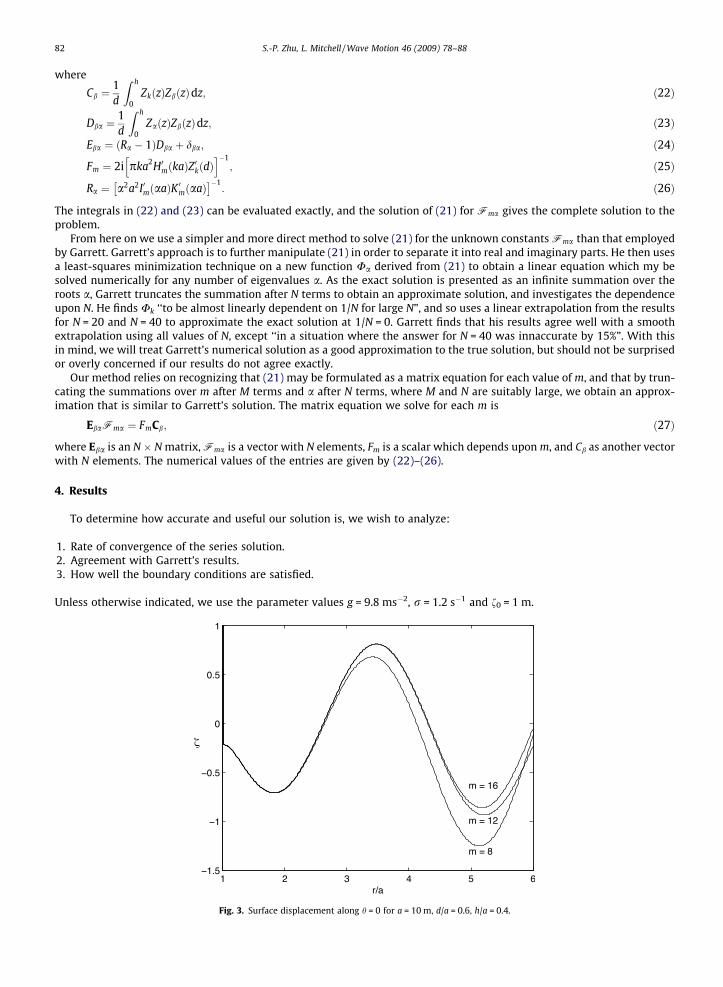
Fig. 3. Surface displacement along h = 0 for a = 10 m, d/a = 0.6, h/a = 0.4.

S.-P. Zhu, L. Mitchell / Wave Motion 46 (2009) 78–88 83
4.1. Convergence of the series solution
The solution converges quickly, with in general no more than 20 terms needing to be taken in the expansion of / for aconvergent solution in both the interior and exterior regions. Fig. 3 shows a surface wave elevation profile for the diffractionproblem for a range of values of m, demonstrating that the solution converges quickly with m. Fig. 4 shows the normed dis-tance between consecutive terms, kfM � fM�1k, with the norm defined as
kfnk ¼XM
m¼0
�m imXR
r¼0
vmðrÞ cos mh;
with R being a number (the radial distance from the center of the cylinder), controlling the total area over which the norm isapplied. In all the test results presented in this paper, it is chosen to be six times the cylinder radius a. This normed distancegives a good measure of the convergence of the series solution.
Fig. 4 shows a rapid decay of the normed distance between consecutive terms as the number of terms included in thecalculation increases. This demonstrates a fast convergence rate using our approach. As the figure shows, taking M = 25
Fig. 4. Error kfm � fm�1k as a function of m, for a = 10 m.
Fig. 5. Amplitude of interior cylinder oscillation for m = 0, d/a = 0.6. The solid line shows our solution, the circles show Garrett’s solution.

Fig. 6. Amplitude of interior cylinder oscillation for m = 1, d/a = 0.6.
Fig. 7. Amplitude of interior cylinder oscillation for m = 2, d/a = 0.6.
Fig. 8. Amplitude of interior cylinder oscillation for m = 3, d/a = 0.6.
84 S.-P. Zhu, L. Mitchell / Wave Motion 46 (2009) 78–88
S.-P. Zhu, L. Mitchell / Wave Motion 46 (2009) 78–88 85
terms is sufficient to guarantee a difference of no more than 10�5 m between successive terms. By our choice of f0 = 1 m, thisimplies a relative error of the same order of magnitude, which should be acceptable for any practical application.
4.2. Comparison with previous results
We compare our results with those obtained by Garrett, who defines
Am ¼FmkZ0kðdÞ
kJ0mðkaÞ; ð28Þ
which is the coefficient of J0mðkrÞ in the expansion of vm(r) in r 6 a. Like Garrett, we plot Am against the dimensionless cylinderradius ka for constant ocean depth d/a = 0.6 and two different cylinder submersions h/a = 0.4, 0.2. We show the results form = 0,1,2,3 in Figs. 5–8. In each figure, the solid line represents our direct solution, and the circles show Garrett’s solution.
The solution for h/a = 0.2 is excellent with both peaks matching those on Garrett’s graphs well, while the second peak forthe h/a = 0.4 solution matches less accurately with Garrett’s solution. For intermediate values of ka between the two peaks
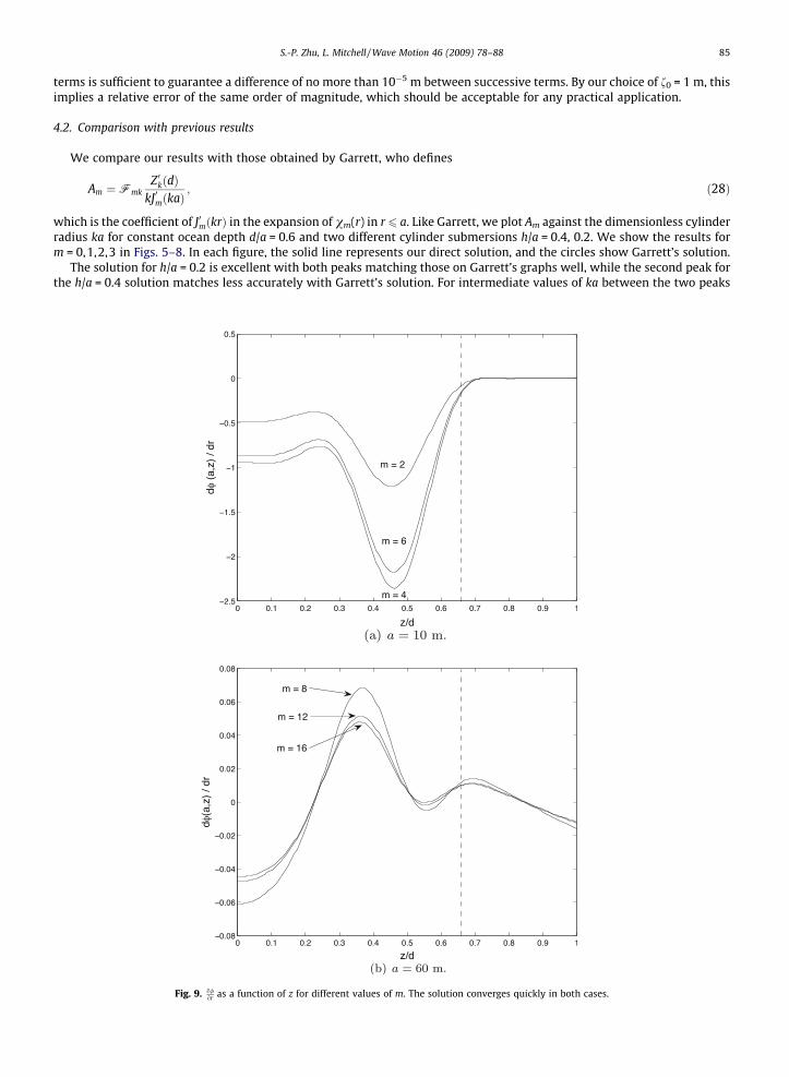
Fig. 9. o/or as a function of z for different values of m. The solution converges quickly in both cases.

86 S.-P. Zhu, L. Mitchell / Wave Motion 46 (2009) 78–88
(roughly 2 < ka < 4) our solution curve is slightly lower than Garrett’s. We believe this is because of the boundary conditionmatching, which we find to be dependent upon cylinder submergence.
4.3. Matching the boundary conditions
The sharp boundary at the bottom of the cylinder, at z = h and r = a, creates a discontinuity in (16) at this point. As we areusing a Fourier series expansion we expect to observe Gibbs phenomenon [11] occurring at the discontinuity. Measuring theseverity of the Gibbs phenomenon at the singularity at r = a and z = h will provide us with information about how accurateour solution is.
Fig. 9(a) and (b) shows plots of o/or at r = a and 0 6 z 6 d for a = 10 m and a = 60 m, respectively. In Fig. 9(a) the solution
curves are visually indistinguishable from each other after six terms, and in Fig. 9(b) are visually indistinguishable after16 terms. The figures show that although the solution converges quickly in both cases, the boundary condition (4) is matchedimperfectly. We find the quality of the matching to the boundary condition to be dependent upon cylinder submergence, asdemonstrated in Fig. 10(a) and (b). The figures show the error per unit submergence depth
Pz2½h;d�
owða;zÞor
��� ���d� h
;
as a function of cylinder height off the ocean floor h. In general the deeper the submergence, the better the matching to theboundary condition at r = a. In both cases, there is a sharp exponential increase in accuracy for submergences greater than90% of the ocean depth, that is for cylinder heights lower than h/a = 0.1.
When the approach presented here is applied to study other cases, e.g., cases with short-crested incident waves, orcases with the chamber of OWC being of a shape other than a perfect circular shape, or even cases with an unevenbottom bathometry, the total number of terms needed to generate a convergent solution may vary too. The satisfactionof the boundary conditions on the vertical wall of an OWC device should always be examined as a measure for theaccuracy of the solution.
Finally, we present example surface wave plots in Figs. 11 and 12. The figures show the diffracted wave heights only fora = 60 m and h/a = 0.4. In both cases plane waves are incident from �1 along the x-axis.
5. Conclusions
A first-order analytical solution for the diffraction of ocean surface waves around a hollow suspended cylinder in anocean of finite constant depth has been derived and presented in closed form. We have formulated the problem usingthe theory presented by Garrett [2], however, have used a different and more direct approach to calculate the numer-ical solution. By writing the problem as a system containing an infinite number of linear equations which we truncateafter a suitable number of terms, we obtain an approximation to the solution that agrees well with Garrett’s. We findour solution more direct and computationally easier to implement than Garrett’s, with good results still provided usingthis technique.
Fig. 10. Boundary condition matching error over submersion depth as a function of h/a.

Fig. 11. Contour plot showing diffracted wave elevation for a = 60 m.
Fig. 12. Contour plot showing wave elevation inside cylinder for a = 60 m.
S.-P. Zhu, L. Mitchell / Wave Motion 46 (2009) 78–88 87
Numerical results are presented for our solution as well as an analysis of the rate of convergence and accuracy ofthe solution in terms how well it matches the boundary conditions. We find that the rate of convergence is very rapid,with less than 30 terms needing to be taken in the series solution to ensure convergence. The boundary conditions arealso met well, with the only numerical issues arising from a singularity in the solution at the bottom of the solid wallof the cylinder. This introduces Gibbs phenomenon at the bottom of the cylinder, the effect of which we find to bedependent upon the cylinder submersion. In general, we find a dramatic improvement in the boundary conditionmatching error for deeper cylinder submersion, with the error decreasing greatly for submersions deeper than 5/6ths of the total ocean depth.
Having obtained a solution for the diffraction problem, a logical extension of the theory is to the coupled diffrac-tion-radiation problem. This will require the formulation and solution for radiating waves produced by an oscillatingsurface pressure, which may be non-uniformly distributed inside a hollow suspended cylinder in an ocean of finiteconstant depth. By obtaining a solution for this problem in the same closed form as the one we have obtained forthe diffraction problem, we will be able to express the solution to the combined diffraction-radiation problem asthe simple linear superposition of the two types of waves. Another possible extension of the research is of course
88 S.-P. Zhu, L. Mitchell / Wave Motion 46 (2009) 78–88
to try to work out the diffraction-radiation problem in the nonlinear wave region or to take into consideration of thevariation of bottom topography. Either of these new directions require considerable effort and will be left for the fu-ture research.
Acknowledgements
Both authors gratefully acknowledge Oceanlinx’s supply of the photo displayed in Fig. 1 of this paper. The second authoralso wishes to acknowledge the support of a University Honors Scholarship from the University of Wollongong while he wasworking on this project.
References
[1] N. Sharmila, P. Jalihal, A.K. Swamy, M. Ravindran, Wave powered desalination system, Energy 29 (11) (2004) 1659–1672.[2] C.J.R. Garrett, Bottomless harbours, J. Fluid Mech. 43 (3) (1970) 433–449.[3] J. Lighthill, Two-dimensional analyses related to wave-energy extraction by submerged resonant ducts, J. Fluid Mech. 91 (1979) 253–317.[4] A.J.N.A. Sarmento, A.F. de O. Falcao, Wave generation by an oscillating surface-pressure and its application in wave-energy extraction, J. Fluid Mech.
150 (1985) 467–485.[5] M.J. Simon, Wave-energy extraction by a submerged cylindrical duct, J. Fluid Mech. 104 (1981) 159–187.[6] J.W. Miles, On surface-wave radiation from a submerged cylindrical duct, J. Fluid Mech. 122 (1982) 339–346.[7] D.V. Evans, R. Porter, Efficient calculation of hydrodynamic properties of OWC-type devices, J. Offshore Mech. Arctic Eng. 119 (4) (1997) 210–218.[8] Y.M.C. Delaure, A. Lewis, 3D hydrodynamic modelling of fixed oscillating water column wave power plant by a boundary element methods, Ocean Eng.
30 (2003) 309–330.[9] C. Josset, A.H. Clement, A time-domain numerical simulator for oscillating water column wave power plants, Renew. Energy 32 (8) (2007) 1379–1402.
[10] G. Kreisel, Surface waves, Q. Appl. Math. 7 (1949) 21–24.[11] G. Arfken, Mathematical Methods for Physicists, Harcourt Academic, London, 2001.