14.3 inspection, test, analysis, and acceptance criteria · within the scope of tier 1. the...
TRANSCRIPT

U.S. EPR FINAL SAFETY ANALYSIS REPORT
14.3 Inspection, Test, Analysis, and Acceptance Criteria
Section 14.3 explains the selection criteria and methods used to develop the U.S. EPR Tier 1 certified design material (CDM) and the inspections, tests, analyses, and acceptance criteria (ITAAC). Tier 1 means the portion of the design-related information contained in a generic FSAR that is approved and certified by the design certification rule (10 CFR Part 52). The design descriptions, interface requirements, and site parameters are derived from Tier 2 information. Tier 1 information includes:
• Definitions and general provisions.
• Design descriptions.
• ITAAC.
• Significant interface requirements.
• Significant site parameters.
The information in the Tier 1 portion of the FSAR is extracted from the detailed information contained in Tier 2. While the Tier 1 information must address the complete scope of the design to be certified, the amount of design information is proportional to the safety-significance of the structures and systems of the design.
There are two material categories in Tier 1: CDM and ITAAC.
• CDM is the design commitment. CDM is in the form of design descriptions, tables, and figures, and is binding for the lifetime of a facility.
• ITAAC will be used to verify the U.S. EPR as-built features. ITAAC material is in tabular format only and expires at initial fuel loading.
Tier 1 consists of five chapters:
• Chapter 1 (Introduction) provides definitions of terms, a figure legend, a list of acronyms and abbreviations, and general provisions applicable to design descriptions, figures, and ITAAC.
• Chapter 2 (System Based Design Descriptions and ITAAC) provides descriptions of safety-significant design features and the ITAAC verifying those features. Chapter 2 is organized by systems, and those systems are grouped into sections for convenience. Every system included in Tier 2 that is within the scope of CDM is listed in Chapter 2. The applicable portions of systems that are partially within the scope of CDM are also included in Chapter 2. Safety-significant systems outside the scope of CDM are addressed as interface requirements in Chapter 4. Interface requirements for systems that are partially in scope are included in Chapter 2 so the CDM for those systems are in one location.
Tier 2 Revision 0 Page 14.3-1

U.S. EPR FINAL SAFETY ANALYSIS REPORT
• Chapter 3 (Non-System Based Design Descriptions and ITAAC) provides CDM not suited to the system design description format of Chapter 2. Material in Chapter 3 addresses security, reliability assurance program (RAP), initial test program (ITP), human factors engineering (HFE), and containment isolation.
• Chapter 4 (Interface Requirements) provides information on safety-significant interface requirements that must be met by site-specific portions of a facility that are not within the scope of CDM. Interface requirements define design features and characteristics so that the site-specific portion of the design conforms to the CDM.
• Chapter 5 (Site Parameters) provides bounding values for safety-significant site parameters that a combined license (COL) applicant referencing the U.S. EPR design will use for site selection. Compliance with these site parameters is verified during the COL application process.
Information presented in Tier 1 contains the proposed ITAAC that are necessary and sufficient to provide reasonable assurance that, if the inspections, tests, and analyses are performed and the acceptance criteria met, a facility that incorporates the U.S. EPR design certification has been constructed and will be operated in accordance with the design certification, the provisions of the Atomic Energy Act, and NRC regulations (10 CFR 52.47(b)(1)).
A COL applicant that references the U.S. EPR design certification will provide ITAAC for emergency planning, physical security, and site-specific portions of the facility that are not included in the Tier 1 ITAAC associated with the certified design (10 CFR 52.80(a)). Additionally, a COL applicant that references the U.S. EPR design certification will describe the selection methodology for site-specific SSC to be included in ITAAC, if the selection methodology is different from the methodology described within the FSAR, and will also provide the selection methodology associated with emergency planning and physical security hardware.
14.3.1 Tier 1, Chapter 1, Introduction
Tier 1, Chapter 1 presents definitions, general provisions, a figure legend, and a list of acronyms and abbreviations. The definitions help minimize interpretation issues over the words and phrases used in Tier 1. The general provisions help with ITAAC verification of the configuration of SSC by providing more details on inspections, tests, and analyses that are common to multiple systems. The ITAAC include inspection of the functional arrangement of the system as described in the design description and as shown in the figures. A figure legend and a list of acronyms facilitate the use and interpretation of U.S. EPR design information. The technical terminology used in Tier 1 is consistent with Tier 2 terminology, industry standards, and regulatory documents.
The criteria for selecting definitions include those in Standard Review Plan (SRP) 14.3 (Reference 1) and any other terms in the FSAR that could be subject to interpretation. The selection process for determining which terms are to be defined begins with a review of the terms and definitions in Tier 2 and the guidance in SRP 14.3. Those terms that are important to Tier 1, potentially ambiguous, or unique to Tier 1 are selected.
Tier 2 Revision 0 Page 14.3-2

U.S. EPR FINAL SAFETY ANALYSIS REPORT
The criteria for inclusion in the general provisions section includes those items needed to clarify the technical requirements that apply to multiple systems, provide guidance on ITAAC implementation, provide guidance on the interpretation of figures, provide guidance on operational considerations, and specify the U.S. EPR core thermal power level. Selecting the general provisions to be included in Tier 1 involves following the SRP 14.3 (Reference 1) guidance and reviewing Tier 2 against the specific criteria previously listed.
14.3.2 Tier 1, Chapter 2, System Based Design Descriptions and ITAAC
Tier 1, Chapter 2 contains CDM system design descriptions (SDD) and associated ITAAC. This chapter is the result of the process to determine which U.S. EPR design features addressed in Tier 2 should be addressed in the Tier 1 CDM SDDs, interface requirements, and site parameters. The selection process considers the U.S. EPR design philosophy of simple, redundant, and active systems coupled with advanced control technology, which reduces the frequency of transients and improves the reliability of the response to those transients. Given this design philosophy, the process of determining the safety-significant features uses the availability of probabilistic risk assessment (PRA) information to determine the significant design features and performance criteria that lead to safe operation. Using this process allows the top level Tier 1 information to be extracted from the more detailed Tier 2 design information. Tier 1, Chapter 2 provides no technical information not already presented in Tier 2.
The Tier 1 information selection process uses two distinct, parallel approaches: those based on equipment classification and those based on features credited in various analyses. The first approach uses specific equipment classification criteria derived from SRP 14.3, including the system checklists in Appendix C of SRP 14.3 (Reference 1). Examples of equipment selection criteria include ASME BPV Code, Section III (Reference 2), Seismic Category I, and IEEE Class 1E. In keeping with the SRP guidance, features provided solely for equipment protection are not included in Tier 1 material.
Tier 1 SDDs developed during the first approach address each system identified in Tier 2. The amount of detail included in a Tier 1 SDD for a specific system is a function of the number and safety significance of the system design features. Systems addressed in Tier 2 that have no safety-significant features are listed in Tier 1 as ‘No entry for this system.’
The second approach to develop Tier 1 material uses assumptions and insights from key safety and integrated plant safety analyses to identify Tier 1 material. Addressing these assumptions and insights in Tier 1 means the integrity of the fundamental analyses is preserved in the as-built facility referencing the U.S. EPR design. The various review teams for this approach were led by a subject matter expert and included, at a minimum, representatives from engineering integration, PRA, and licensing. The following areas were reviewed for safety-significant design features:
• Design Basis Accidents (DBA) — Analytical input summaries and key assumptions for the safety analyses were reviewed. Also, system engineers performing containment analyses and overpressure protection analyses identified items to be
Tier 2 Revision 0 Page 14.3-3
U.S. EPR FINAL SAFETY ANALYSIS REPORT
included as DBA safety-significant design features. The results are in Table 14.3-1—DBA Analysis.
• Radiological Protection — The radiological engineering information record that summarizes the design input for radiological analyses was reviewed for safety-significant items. The results are in Table 14.3-2—Radiological Analysis.
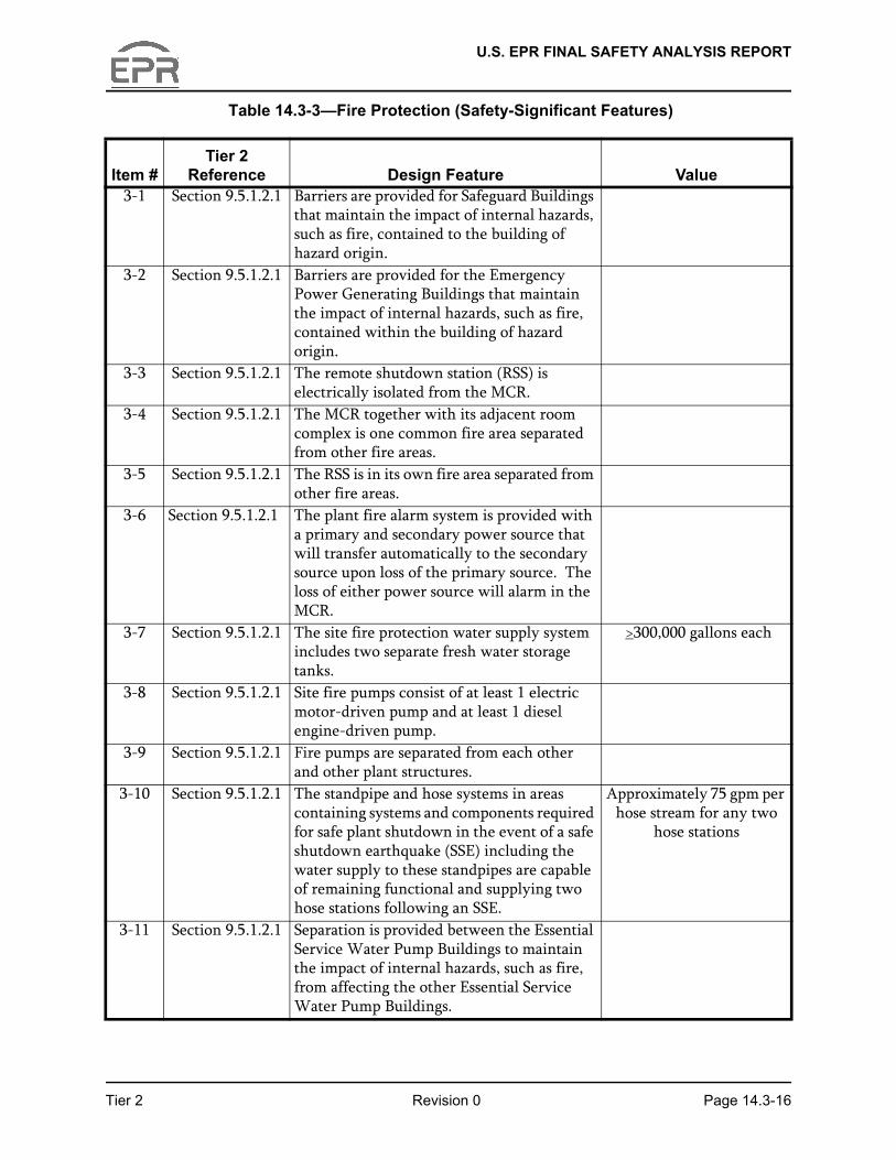
• Fire Protection — Fire hazards analyses were reviewed for safety-significant design features. The results are in Table 14.3-3—Fire Protection.
• Flooding Protection — Flooding evaluations were reviewed for safety-significant design features. The results are in Table 14.3-4—Flooding Analysis.
• Anticipated Transient Without Scram (ATWS) —10 CFR 50.62 (the ATWS rule) and the engineering evaluation addressing ATWS were reviewed for safety-significant design features. The results are in Table 14.3-5—ATWS.
• PRA and Severe Accident — The PRA insights report and severe accident analyses were reviewed for safety-significant design features. Using the PRA insights report provided a process to identify non-safety-related features that are safety-significant and otherwise may not have been identified. The results are in Table 14.3-6—PRA and Severe Accident Analysis.
• Licensing — Three Mile Island (TMI) items from 10 CFR 50.34(f) and high-priority generic safety issues (GSI) items from NUREG-0933, Appendix B were reviewed for safety-significant design features relevant to the U.S. EPR design. The items were then compared to the other Section 14.3 tables for redundancy. Items not already addressed by another Section 14.3 table or not already addressed by other Tier 1 criteria are listed in Table 14.3-7—Licensing.
In addition to identifying the safety-significant features, the tables developed during the second approach (team reviews of analyses) list the Tier 2 section that describes the identified design feature. As part of the Tier 1 development process, roadmaps were also created to maintain consistency between Tier 1 and Tier 2 material. Additionally, the information contained in the Tier 2, Section 14.3 tables was verified to be included in Tier 1, and Tier 1 material related to testing was verified to be consistent with the initial test program in Tier 2, Section 14.2.
The U.S. EPR systems are listed in Table 14.3-8—ITAAC Screening Summary. Systems within the scope of Tier 1 or that contain ITAAC are identified in the table. Conceptual systems only consisting of interface requirements are not considered within the scope of Tier 1. The Kraftwerks Kennzeichen System (KKS) codes are also listed in Table 14.3-8 because Tier 1 equipment tags use the KKS identification system.
The commitments listed in the Tier 1 ITAAC tables will be verified to satisfy the acceptance criteria using the inspection, test, or analysis listed. If the as-built item satisfies the acceptance, then the ITAAC is complete. For items not satisfying the acceptance criteria, corrective actions will be taken to resolve the issue.
Tier 2 Revision 0 Page 14.3-4

U.S. EPR FINAL SAFETY ANALYSIS REPORT
14.3.2.1 Content of Tier 1 System Design Descriptions
The content of the Tier 1 SDDs for systems and structures reflects the graded approach previously approved for other certified designs, as described in SRP 14.3. This graded approach results in only the top level design features that are safety significant being included in the Tier 1 SDDs. The level of detail provided similarly reflects a graded approach, with the detail provided commensurate with the safety significance of the system. The SDDs constitute the CDM and consist of descriptive material, tables, and figures.
The checklists provided in Appendix C of SRP 14.3 were used to guide the content of the U.S. EPR Tier 1 SDDs. Generally, the following information is included:
• A brief statement of the purpose of the system or structure.
• A listing of the safety-significant functions.
• System location.
• Key design features.
• Classifications (e.g., ASME Code, seismic category, IEEE Class 1E, environmental qualification).
• Minimum controls and displays.
• 1E power requirements.
• Interface requirements.
The SDDs generally contain no numerical values. Numerical values listed in the tables within Chapter 2 are provided to be used as the basis for ITAAC acceptance criteria and appear in the associated ITAAC acceptance criteria that verify the as-built facility. To the extent practical, standardized wording is used in the SDDs to avoid confusion.
The following types of information presented in Tier 2 are not addressed in Tier 1 for the indicated reasons:
• Proprietary and safeguards information because the Office of the Federal Register requires that information incorporated into the design certification rule is publicly available.
• Portable equipment and replaceable items because the certified design descriptions focus on the permanent physical characteristics of the as-built facility and portable equipment, and replaceable items are controlled through other operational programs.
• Programmatic requirements related to operations, maintenance, and other programs are not detailed in the Tier 1 design descriptions.
Tier 2 Revision 0 Page 14.3-5

U.S. EPR FINAL SAFETY ANALYSIS REPORT
• Programmatic aspects of the design and construction processes, such as worker selection, qualification, and training, are not covered in the CDM.
• Operational issues, such as procedures and training, are not design features and therefore are not presented in Tier 1.
• Integrated test requirements are presented in Tier 1, but specific details of the initial test program are not presented in Tier 1. Details of the initial testing program are presented in Tier 2, Section 14.2.
• The use of codes and standards (with the exception of the ASME Code) are minimized in Tier 1 design descriptions because the Tier 1 SDDs are intended to stand alone. Specific information needed from external documents is included in the applicable Tier 1 chapter when necessary.
14.3.2.2 Selection Criteria for ITAAC
An ITAAC table is provided for each Tier 1 system that has a design description. The ITAAC table defines the activities to be performed to verify that the as-built system conforms to the design features contained within the design description, as well as the acceptance criteria for those activities.
The following items are considered when developing the ITAAC entries:
• Section 1 of the SDDs provides a brief summary of the Tier 1 functions. Commitments of plant features begin in Section 2 and are in each subsequent section of the SDD.
• ITAAC are only intended to verify the as-built configuration of important design features and performance characteristics described in the design descriptions. Therefore, there are no ITAAC for features not addressed in the design description.
• Each U.S. EPR system that has a design description also has associated ITAAC. The scope of the ITAAC corresponds to the scope of the design descriptions.
• A single inspection, test, or analysis may verify multiple provisions in the certified design description.
• The inspections, tests, and analyses must be completed and the acceptance criteria verified prior to the initial loading of fuel (10 CFR 52.103).
14.3.2.3 Content of ITAAC
ITAAC tables for the U.S. EPR use the standard format in Appendix D of SRP 14.3. The ITAAC tables have columns for design commitments; inspections, tests, and analyses; and acceptance criteria. Each design commitment in the left-hand column has an associated inspection, test, or analysis requirement in the middle column with the applicable acceptance criteria listed in the right-hand column.
Tier 2 Revision 0 Page 14.3-6

U.S. EPR FINAL SAFETY ANALYSIS REPORT
Column 1 (Design Commitment) defines the specific commitment extracted from the SDD features.
Column 2 (Inspections, Tests, and Analyses) defines the specific method the licensee will use to demonstrate that the specific design commitment in Column 1 has been met. The methods used are inspection, test, analysis, or a combination of the three:
• Inspections are used when verification can be done by visual observations, physical examinations, walkdowns, or by reviewing records that are based on observations or examinations. The inspections required for basic configuration walkdown follow the general provisions in Tier 1, Section 1.2.
• Tests mean that either operating or establishing specified conditions to evaluate the performance of the as-built structures, systems, or components. In addition to testing final and installed equipment, examples of alternative testing methods include factory testing, test facility testing, and laboratory testing. Testing can also include type testing such as might be performed to demonstrate qualification to meet environmental requirements.
• Analysis is used when verification can be done by calculation or engineering evaluation of the as-built SSC.
For the methods used to demonstrate commitment satisfaction, supporting details are provided in Tier 2. The initial test program is described in Section 14.2 of Tier 2 and covers both visual inspections and tests. The details in Tier 2 are not referenced in Tier 1 CDM and are not part of the certified design.
Column 3 (Acceptance Criteria) depends upon the design feature to be verified and the method used for the verification. Acceptance criteria are objective and clear to avoid confusion over whether or not acceptance criteria have been satisfied. Some acceptance criteria contain numerical values that are not specifically identified in the Tier 1 design description or the ITAAC table design commitments column. This is acceptable because the design description defines the important design feature that needs to be included in the CDM, whereas the numerical value is a measurement standard that determines if the feature has been provided.
14.3.3 Tier 1, Chapter 3, Non-System Based Design Descriptions and ITAAC
The format and selection process for Tier 1, Chapter 3 is similar to Tier 1, Chapter 2 in that it includes CDM and ITAAC tables. Tier 1, Chapter 3 addresses the following non-system based topics:
• Section 3.1 – Security.
• Section 3.2 - Reliability assurance program (RAP).
• Section 3.3 - Initial testing program (ITP).
• Section 3.4 - Human factors engineering (HFE).
• Section 3.5 - Containment isolation.
Tier 2 Revision 0 Page 14.3-7

U.S. EPR FINAL SAFETY ANALYSIS REPORT
14.3.4 Tier 1, Chapter 4, Interface Requirements
Interface requirements are items to be met by the site-specific portions of a facility that are not within the scope of the certified design. The site-specific portions of the design are those that depend on site characteristics. Interface requirements define the design features and characteristics that demonstrate that the site-specific portion of the design conforms to the certified design. Interface requirements comply with 10 CFR 52.47(a)(26) requirements.
14.3.5 Tier 1, Chapter 5, Site Parameters
Tier 1, Chapter 5 defines safety-significant site parameters that are the basis for the standard plant design presented in the U.S. EPR design certification application. The list of site parameters follows the suggested list contained in SRP 14.3 and corresponds with the requirements for site parameter information contained in 10 CFR 52.47(a)(1). Compliance with these site parameters is verified during the COL application process, so no ITAAC are necessary for site parameters.
14.3.6 References
1. NUREG-0800, “Standard Review Plan for the Review of Safety Analysis Reports for Nuclear Power Plants,” Nuclear Regulatory Commission, March 2007.
2. ASME Boiler and Pressure Vessel Code, Section III, “Rules of Construction of Nuclear Facility Components, “Class 1, 2, and 3 Components, The American Society of Mechanical Engineers, 2004, (No Addenda).
Tier 2 Revision 0 Page 14.3-8

U.S. EPR FINAL SAFETY ANALYSIS REPORT
Table 14.3-1—Design Basis Accident Analysis (Safety-Significant Features)
Sheet 1 of 5
Item #Tier 2
Reference Design Feature Value1-1 Table 4.4-1 Initial rated reactor power is 4590 MWt. 4590 MWt
1-2 Table 3.4.9-1 RCCA bank withdrawal rate. Maximum 30 in/min (75 steps/min)
1-3 Table 5.1-1 RCS loop flowrate. Minimum 119,692 gpm/loop.Maximum 134,662 gpm/loop.
1-4 Section 5.2.2.2.2 CVCS charging pump flow. Maximum runout flow (delivered to the cold legs) of 112.66 lbm/sec (total for both pumps)
1-5 Section 5.4.1.2.2 The reactor coolant pumps have a device to prevent reverse rotation.
1-6 Section 5.4.1.4 RCS flow coastdown. Minimum flow (% of initial flow) after pump trip:Time - Flow0.0 sec – 100 %1.0 sec - 94.03 %2.0 sec - 87.59 %4.0 sec - 77.01 %6.0 sec - 68.66 %8.0 sec - 61.81 %10.0 sec - 56.10 %20.0 sec - 38.00 %
1-7 Table 5.4-2 SG steam outlet flow restrictor throat area. Maximum 1.39 ft2
1-8 Table 5.4-9 PSV capacity. Minimum 661,400 lbm / hr per valve at 2535 psig (Total of 3 valves)
1-9 Table 5.4-9 PSV opening time. Maximum 0.89 sec (including pilot valves).
1-10 Section 6.2.1.1.2 Containment design pressure. 62 psig.1-11 Table 6.2-1 Containment Free Volume. Minimum 2.755 x 106 ft3
1-12 Table 6.3-1 Accumulator total volume. Minimum 1942.3 ft3 per accumulator (total of 4 accumulators).
1-13 Table 6.3-1 Accumulator fL/D + K. Minimum 2.78 for a flow area of 0.3941 ft2
Tier 2 Revision 0 Page 14.3-9

U.S. EPR FINAL SAFETY ANALYSIS REPORT
1-14 Table 6.3-2 Pumped LHSI flowrate. Minimum runout flowrate per train (delivered to the cold leg) is 312.2 lbm/s (cross-connects are closed.)
1-15 Table 6.3-2 LHSI shutoff head. Minimum 302 psia (cold leg pressure)
1-16 Table 6.3-3 Pumped MHSI flowrate. Minimum runout flowrate per train (delivered to the cold leg) is 130.1 lbm/s.
1-17 Table 6.3-3 Pumped MHSI flowrate. Maximum runout flowrate per train (delivered to the cold leg) is 153.1 lbm/s.Maximum runout flowrate per train (delivered to the cold leg with the large miniflow line open) is 112.0 lbm/s.
1-18 Table 6.3-3 MHSI shutoff head. Minimum 1300 psia (cold leg pressure).
1-19 Table 6.3-3 MHSI shutoff head. Maximum 1407 psia (cold leg pressure).Maximum 614 psia (cold leg pressure with large miniflow line open).
1-20 Table 6.3-4 IRWST water volume. Minimum 66,886 ft3 (500,342 gal).
1-21 Section 7.2.1.2.1 A reactor trip occurs on low DNBR.1-22 Section 7.2.1.2.2 A reactor trip occurs on high linear power
density.1-23 Section 7.2.1.2.3 A reactor trip occurs on high neutron flux
rate of change. 1-24 Section 7.2.1.2.4 A reactor trip occurs on high core power or
low saturation temperature margin in two or more loops.
1-25 Section 7.2.1.2.5 A reactor trip occurs on low RCS loop flowrates on 2 or more loops.
1-26 Section 7.2.1.2.6 A reactor trip occurs on low-low loop flowrate on one loop.
Table 14.3-1—Design Basis Accident Analysis (Safety-Significant Features)
Sheet 2 of 5
Item #Tier 2
Reference Design Feature Value
Tier 2 Revision 0 Page 14.3-10

U.S. EPR FINAL SAFETY ANALYSIS REPORT
1-27 Section 7.2.1.2.7 A reactor trip occurs on low RC pump speed on 2 or more RC pumps.
1-28 Section 7.2.1.2.8 A reactor trip occurs on high neutron flux during startup.
1-29 Section 7.2.1.2.10 A reactor trip occurs on low pressurizer pressure.
1-30 Section 7.2.1.2.11 A reactor trip occurs on high pressurizer pressure.
1-31 Section 7.2.1.2.12 A reactor trip occurs on high pressurizer level.
1-32 Section 7.2.1.2.13 A reactor trip occurs on low hot leg pressure in two of four loops.
1-33 Section 7.2.1.2.14 A reactor trip occurs on high SG steam pressure rate of decrease.
1-34 Section 7.2.1.2.15 A reactor trip occurs on low SG steam pressure.
1-35 Section 7.2.1.2.16 A reactor trip occurs on high SG steam pressure.
1-36 Section 7.2.1.2.17 A reactor trip occurs on low SG secondary water level.
1-37 Section 7.2.1.2.18 A reactor trip occurs on high SG secondary water level.
1-38 Section 7.2.1.2.20 A reactor trip occurs on SIS actuation.1-39 Section 7.2.1.2.21 A reactor trip occurs on emergency
feedwater actuation.1-40 Section 7.2.1.2.22 A manual reactor trip is provided.1-41 Section 7.3.1.1.3 The EFW system is isolated on high SG
secondary water level.1-42 Section 7.3.1.2.1 The SIS (4 trains) is activated on low
pressurizer pressure or on low margin to saturation.
1-43 Section 7.3.1.2.2 The EFW system (one per SG) is activated on low SG secondary water level and on SIS concurrent with LOOP.
1-44 Section 7.3.1.2.4 A partial cooldown is accomplished by using the MSRTs to depressurize the SG secondary side in response to actuation of the SIS.
Table 14.3-1—Design Basis Accident Analysis (Safety-Significant Features)
Sheet 3 of 5
Item #Tier 2
Reference Design Feature Value
Tier 2 Revision 0 Page 14.3-11

U.S. EPR FINAL SAFETY ANALYSIS REPORT
1-45 Sections 7.3.1.2.7 and 7.3.1.2.14
Main steam line isolation occurs on 1) high SG steam pressure rate of decrease, 2) low SG steam pressure, or 3) high SG level and initiation of partial cooldown.
1-46 Section 7.3.1.2.8 The PS will initiate MFW isolation. 1-47 Section 7.3.1.2.12 The PS will initiate EDG startup and
sequence loads.1-48 Section 7.3.1.2.15 A trip of all reactor coolant pumps occurs on
low P across a reactor coolant pump concurrent with an SIS signal.
1-49 Section 7.3.1.2.17 A turbine trip is initiated on a reactor trip signal.
1-50 Table 10.3-2 MSRT flowrate. Minimum of 2,844,146 lbm / hr at valve inlet static pressure of 1370 psig per train. (Total of 4 MSRTs)
1-51 Table 10.3-2 MSSV open setpoints. Maximum 1504 psig MSSV1.Maximum 1535 psig MSSV2.
1-52 Table 10.3-2 MSSV capacities. Minimum 1,422,073 lbm / hr per valve at 1504 psig (MSSV1) and 1535 psig (MSSV2). (Total of 4 MSSV1 valves and 4 MSSV2 valves)
1-53 Section 10.4.9.2.1 EFW pool volume sufficient to achieve cold shutdown.
Minimum 300,000 gallons (total for 4 pools).
1-54 Section 10.4.9.2.1 Cross-connections allow EFW pump suction on all EFW pools and pump discharge alignment with any SG.
1-55 Section 10.4.9.2.1 Alignment of EFW pumps with any SG can be accomplished from the main control room.
1-56 Section 10.4.9.2.1 Emergency power provides power to essential safety equipment if there is a loss of normal power.
Table 14.3-1—Design Basis Accident Analysis (Safety-Significant Features)
Sheet 4 of 5
Item #Tier 2
Reference Design Feature Value
Tier 2 Revision 0 Page 14.3-12

U.S. EPR FINAL SAFETY ANALYSIS REPORT
1-57 Section 10.4.9.2.1 and Table 10.4.9-
1
EFW flowrate per SG. Minimum flow of 198,416 lbm/hr (or 399.4 gpm at 122 F) at pressures up to 1426.1 psia and linearly ramping to 61,906 lbm/hr (or 124.6 gpm at 122 F) at 1568.2 psia.
1-58 Table 10.4.9-1 EFW flowrate to a depressurized SG. Maximum 490 gpm.1-59 Table 15.0-8 MSRT opening pressure. Maximum of 1414.7 psia1-60 Table 15.0-8 MSRT closure pressure. Maximum of 609.7 psia.1-61 Table 15.0-8 MSRIV/MSRT opening time. Maximum 1.8 s1-62 Table 15.0-8 MSIV closure time. Maximum 5 s after signal1-63 Table 15.0-8 Pumped safety injection startup time from
event detection to full flow.Maximum 15 s (with offsite power available).Maximum 40 s (with loss of offsite power).
1-64 Table 15.0-8 EFW pump startup time from event detection to full flow.
Maximum 15 seconds (with offsite power available).Maximum 60 seconds (with loss of offsite power).
1-65 Table 15.0-9 PSV open setpoints. Maximum 2600.4 psia.1-66 Section 15.6.5.2.2 MSRT partial cooldown. Ramped from a maximum
opening pressure of 1414.7 psia to a maximum of 900 psia at a rate sufficient to reduce temperature 180 F/hr if SIS is actuated
Table 14.3-1—Design Basis Accident Analysis (Safety-Significant Features)
Sheet 5 of 5
Item #Tier 2
Reference Design Feature Value
Tier 2 Revision 0 Page 14.3-13

U.S. EPR FINAL SAFETY ANALYSIS REPORT
Table 14.3-2—Radiological Analysis (Safety-Significant Features)
Sheet 1 of 2
Item #Tier 2
Reference Design Feature Value2-1 Section 6.2.3 The annulus ventilation system provides a
sub-atmospheric pressure between the inner and outer containment shells during postulated accidents.
At least -0.25 inches of H2O in < 305 seconds from initiation of signal
2-2 Section 6.2.6.1 Leakage rate (La) through the primary containment.
<0.25 w/o per day
2-3 Section 6.3.2.2 Post LOCA pH control >7 is provided for the in-containment refueling water storage tank (IRWST) with TSP-dodecahydrate.
>12,200 lbm TSP
2-4 Sections 9.1.2 The spent fuel pool water level is maintained above the spent fuel.
>23 feet
2-5 Sections 9.4.1.1 and 9.4.1.2.3,
15.0.3.4.1
Outside air supply to the main control room (MCR) is diverted to filtration system upon actuation by a primary containment isolation signal (PCIS) or by high radiation levels in the air intake ducts.
<1 minute
2-6 Section 9.4.1.2.3 Filtered outside air supply to the MCR is sufficient to maintain a positive pressure relative to areas outside the MCR pressure boundary.
>1/8 inch water gauge
2-7 Section 9.4.1.2.3 The MCR post-isolation ventilation recirculation system diverts air through a filtration system.
>3000 cfm
2-8 Section 15.0.3.4.1 MCR ventilation unfiltered air inleakage. <50 cfm2-9 Sections 9.4.2,
9.4.3, 9.4.5, 9.4.8, and 9.4.14
The Fuel Building and the radiological controlled area of safeguard building ventilation systems maintain negative pressure in the buildings with respect to the outside atmosphere, to prevent leakage of potentially contaminated air to the environment.
2-10 Section 15.0.3.11.2
Closure time for containment isolation valves for pre-isolation filtered exhaust (KLA system).
<10 seconds
2-11 Section 12.3.2.3 Building wall thicknesses for the Reactor Building and annulus (UJA) provide shielding to meet the radiation zone and access requirements for postaccident mitigation.
Tier 2 Revision 0 Page 14.3-14

U.S. EPR FINAL SAFETY ANALYSIS REPORT
2-12 Section 12.3.2.3 Building wall and floor thicknesses for the safeguards buildings 1, 2, 3, and 4 (UJH/UJK) provide shielding to meet the radiation zone and access requirements for post accident mitigation.
2-13 Section 12.3.2.3 Building wall and floor thicknesses for the fuel building (UFA) provide shielding to meet the radiation zone and access requirements for postaccident mitigation.
Table 14.3-2—Radiological Analysis (Safety-Significant Features)
Sheet 2 of 2
Item #Tier 2
Reference Design Feature Value
Tier 2 Revision 0 Page 14.3-15
U.S. EPR FINAL SAFETY ANALYSIS REPORT
Table 14.3-3—Fire Protection (Safety-Significant Features)
Item #Tier 2
Reference Design Feature Value3-1 Section 9.5.1.2.1 Barriers are provided for Safeguard Buildings
that maintain the impact of internal hazards, such as fire, contained to the building of hazard origin.
3-2 Section 9.5.1.2.1 Barriers are provided for the Emergency Power Generating Buildings that maintain the impact of internal hazards, such as fire, contained within the building of hazard origin.
3-3 Section 9.5.1.2.1 The remote shutdown station (RSS) is electrically isolated from the MCR.
3-4 Section 9.5.1.2.1 The MCR together with its adjacent room complex is one common fire area separated from other fire areas.
3-5 Section 9.5.1.2.1 The RSS is in its own fire area separated from other fire areas.
3-6 Section 9.5.1.2.1 The plant fire alarm system is provided with a primary and secondary power source that will transfer automatically to the secondary source upon loss of the primary source. The loss of either power source will alarm in the MCR.
3-7 Section 9.5.1.2.1 The site fire protection water supply system includes two separate fresh water storage tanks.
>300,000 gallons each
3-8 Section 9.5.1.2.1 Site fire pumps consist of at least 1 electric motor-driven pump and at least 1 diesel engine-driven pump.
3-9 Section 9.5.1.2.1 Fire pumps are separated from each other and other plant structures.
3-10 Section 9.5.1.2.1 The standpipe and hose systems in areas containing systems and components required for safe plant shutdown in the event of a safe shutdown earthquake (SSE) including the water supply to these standpipes are capable of remaining functional and supplying two hose stations following an SSE.
Approximately 75 gpm per hose stream for any two
hose stations
3-11 Section 9.5.1.2.1 Separation is provided between the Essential Service Water Pump Buildings to maintain the impact of internal hazards, such as fire, from affecting the other Essential Service Water Pump Buildings.
Tier 2 Revision 0 Page 14.3-16

U.S. EPR FINAL SAFETY ANALYSIS REPORT
Table 14.3-4—Flooding Analysis (Safety-Significant Features) Sheet 1 of 2
Item #Tier 2
Reference Design Feature Value4-1 Section 3.4.1.1.1 The probable maximum flood elevation is one
foot below finished yard grade.1 foot
4-2 Section 3.4.1.1.1 Portions of seismic category I structures located below grade elevation are protected from external flooding by waterstops, water tight seals, and waterproofing.
4-3 Section 3.4.1.1.2 Barriers are provided for Safeguard Buildings that maintain the impact of internal hazards, such as flood and energy line break, contained to the building of hazard origin.
4-4 Section 3.4.1.1.2 Barriers are provided for the Emergency Power Generating Buildings that maintain the impact of internal hazards, such as flood, contained within the building of hazard origin.
4-5 Section 3.4.1.1.2 Division walls in seismic category I structures below elevation +0 feet 0 inches provide strict separation and serve as flood barriers to prevent spreading of flood water to adjacent divisions.
4-6 Section 3.4.1.1.2 Rooms below level +0 feet 0 inches within divisionally separated buildings are provided with sufficient interconnections to keep the maximum released water volume stored within the affected division.
4-7 Section 3.4.1.1.2 Above level +0 feet 0 inches, water ingress to neighboring divisions is prevented by a combination of water resistant doors and drain paths that direct water to levels below +0 feet 0 inches.
4-8 Section 3.4.1.1.2 In certain locations, guard pipe enclosing high energy lines reduces the likelihood of flooding.
4-9 Section 3.4.1.1.2 Safety-related electrical systems are arranged in the upper building levels.
4-10 Section 3.4.1.2.2 Critical locations are equipped with leakage and flood detection instrumentation to provide automatic isolation of systems with greatest flooding potential and timely indication to the MCR.
Tier 2 Revision 0 Page 14.3-17

U.S. EPR FINAL SAFETY ANALYSIS REPORT
14-11 Section 3.4.1.1.2 Separation is provided between the Essential Service Water Pump Buildings to maintain the impact of internal hazards, such as fire, from affecting the other Essential Service Water Pump Buildings.
Table 14.3-4—Flooding Analysis (Safety-Significant Features) Sheet 2 of 2
Item #Tier 2
Reference Design Feature Value
Tier 2 Revision 0 Page 14.3-18

U.S. EPR FINAL SAFETY ANALYSIS REPORT
Table 14.3-5—ATWS (Safety-Significant Features)
Item #Tier 2
Reference Design Feature Value5-1 Sections 6.8
and 15.8.1.5The extra borating system (EBS) is available as a redundant means to bring the reactor to hot standby on conditions indicative of an ATWS.
5-2 Section 6.8.2 EBS consists of two trains.5-3 Section 6.8.2.1 Activation of EBS is manual.5-4 Section 7.8.1.1 The diverse actuation subsystem, which is
part of the process automation system, includes equipment from sensor output to the final actuation device that is independent from the reactor protection system to provide a diverse reactor trip.
5-5 Section 7.8.1.1 The diverse actuation subsystem, which is part of the process automation system, automatically initiates the emergency feedwater system and initiates a turbine trip under conditions indicative of an ATWS.
Tier 2 Revision 0 Page 14.3-19

U.S. EPR FINAL SAFETY ANALYSIS REPORT
Table 14.3-6—PRA and Severe Accident Analysis (Safety-Significant Features)
Sheet 1 of 4
Item #Tier 2
Reference Design Feature Value6-1 Section
1.2.3.1.2Each of the four Safeguard Buildings houses a separate safety division.
6-2 Section 1.2.3.1.2
Each Safeguard Building houses one train of each of the following systems:Component cooling water system (CCWS)Emergency feedwater system (EFWS)Safety injection system and residual heat removal system (SIS/RHRS) which contains MHSI, LHSI, and AccumulatorEssential service water system (ESWS)
6-3 Section 1.2.3.1.2
Safeguard Buildings are designed to contain the impacts of internal hazards (e.g., fires, high-energy line break, floods) to the building of origin.
6-4 Section 1.2.3.1.2
Each ESWS pump is located within a separate ESWS pump house. Each ESWS pump house is associated with a cooling tower.
6-5 Section 3.8 The Shield Building, Containment Building, Safeguard Buildings, Fuel Building, Essential Service Water Buildings, Essential Service Water Cooling Towers, and Emergency Power Generating Buildings are classified as Seismic Category I.
6-6 Section 3.8.1 The Containment Building is pre-stressed concrete and the Shield Building is reinforced concrete.
6-7 Section 5.4.1.2.1
The U.S. EPR RCP has a standstill seal system. It provides backup seal capability independent of normal seal when the RCP is stopped.
6-8 Section 6.3 The four trains of SIS/RHRS inject borated water into the reactor coolant system to compensate for the loss of RCS inventory or to remove residual heat from the RCS.
6-9 Section 6.3 Each IRWST (SIS train) suction inlet line has debris screens.
Tier 2 Revision 0 Page 14.3-20

U.S. EPR FINAL SAFETY ANALYSIS REPORT
6-10 Section 6.3 The in-containment refueling water storage tank (IRWST) performs the following functions:Supplies water to the Safety Injection System (SIS) and to the Severe Accident Heat Removal System (SAHRS) Provides water to flood the spreading area
6-11 Figure 6.4-1 and Section 7.4.1.3.4
The MCR is located in Safeguard Buildings 2/3 and is separate from the RSS.
6-12 Section 6.8 Two trains of the extra borating system (EBS) provide injection of boric acid.
6-13 Section 7.2 The protection system (PS) provides a means of performing the automatic and manual reactor trip.
6-14 Section 7.4.1.3.4
The RSS is located in Safeguard Building 3.
6-15 Section 7.4.1.3.4
The RSS has the ability to bring the plant to shutdown independent of the MCR.
6-16 Section 8.1.2 Each safety division includes a dedicated DC electrical division.
6-17 Section 8.3.1.1.5
There are 4 emergency diesel generators (EDG), one for each safety division.
6-18 Section 8.4 There are 2 station blackout (SBO) diesels, for Divisions 1 and 4.
6-19 Section 8.4 SBO DGs are independent and diverse from the EDGs.
6-20 Sections 9.2.1 and 9.2.2
ESWS/CCWS trains remove heat from operational loads, safety-related components and decay heat during shutdown or accidents.
6-21 Sections 9.2.1 and 9.2.2
Each CCWS/ESWS train has its own dedicated cooling tower.
6-22 Sections 9.2.1 and 9.2.2
The ESWS/CCWS is designed with one dedicated train that cools the SAHRS heat exchanger.
6-23 Section 9.3.4 The CVCS provides RCP seal injection.6-24 Section 9.4.1 MCR air conditioning system maintains
positive pressure and is independent of other ventilation systems.
Table 14.3-6—PRA and Severe Accident Analysis (Safety-Significant Features)
Sheet 2 of 4
Item #Tier 2
Reference Design Feature Value
Tier 2 Revision 0 Page 14.3-21

U.S. EPR FINAL SAFETY ANALYSIS REPORT
6-25 Section 9.4.1 The ventilation system for the RSS is independent of the MCR air conditioning system.
6-26 Sections 9.4.5 and 9..4.6
Each safety division has its own dedicated HVAC system.
6-27 Section 10.3 Each of four main steam lines includes one main steam relief valve train and two main steam safety valves.
6-28 Section 10.3 Each main steam relief train has a fast acting main steam relief isolation valve and a main steam relief control valve.
6-29 Section 10.4.7 The startup and shutdown system supplies feedwater to the SGs for low power operation.
6-30 Section 17.4 Reliability assurance program provides assurance that the reliability of risk-significant SSCs is maintained consistent with their PRA assumptions.
6-31 Section 19.2 There is one train of SAHRS that provides containment heat removal and provides a means of cooling the IRWST.
6-32 Section 19.2 The severe accident depressurization valves provide capability to depressurize the RCS.
6-33 Section 19.2 Upon receiving an SIS signal, the MSRTs initiate an automatic partial cooldown of the RCS to permit the MHSI system to inject to the RCS.
6-34 Section 19.2 Thermocouples indicate core outlet temperature.
6-35 Section 19.2 The combustible gas control system (CGCS) contains passive autocatalytic recombiners (PAR) in-containment for hydrogen control.
6-36 Section 19.2 The core melt stabilization system (CMSS) includes a lining of sacrificial concrete located in the bottom of the reactor pit.
6-37 Section 19.2 The CMSS includes a lining of sacrificial concrete located in the spreading room.
6-38 Section 19.2 The CMSS sacrificial concrete in the reactor pit is backed by a protective layer of refractory material.
Table 14.3-6—PRA and Severe Accident Analysis (Safety-Significant Features)
Sheet 3 of 4
Item #Tier 2
Reference Design Feature Value
Tier 2 Revision 0 Page 14.3-22

U.S. EPR FINAL SAFETY ANALYSIS REPORT
6-39 Section 19.2 There is a melt plug in the center of the reactor pit.
6-40 Section 19.2 Reactor pit designed with no direct flow path to upper containment.
6-41 Section 19.2 Reactor pit concrete supports are provided.6-42 Section 19.2 A flooding wall exists to limit the ingress of
water to the spreading area.6-43 Section 19.2 Passive valves are provided to initiate flow of
water from the IRWST.6-44 Section 19.2 A flow limiting device exists in the SAHRS
suction line from the IRWST to limit backflow into the IRWST.
6-45 Section 19.2 The floor and walls of the spreading room contain cooling channels.
6-46 Section 19.2 SAHRS provides a means to spray water into the containment for heat and airborne fission product removal.
6-47 Section 19.2 SAHRS provides a means to inject water to the CMSS cooling structure.
Table 14.3-6—PRA and Severe Accident Analysis (Safety-Significant Features)
Sheet 4 of 4
Item #Tier 2
Reference Design Feature Value
Tier 2 Revision 0 Page 14.3-23

U.S. EPR FINAL SAFETY ANALYSIS REPORT
Table 14.3-7—Licensing (Safety-Significant Features)
Item #Tier 2
Reference Design Feature Value7-1 Section
18.7.1.3.6, and Tables 18.7-1
and 18.7-2
Pressurizer safety relief valve position indication in the MCR and RSS.
7-2 Section 18.7.1.3.7
Automatic and manual emergency feedwater system initiation.
7-3 Section 18.7.1.3.7, and Tables 18.7-1
and 18.7-2
Emergency feedwater system flow indication in the main control room and remote shutdown station.
7-4 Section 18.7.1.3.8
The MCR and RSS contain instrumentation to monitor:• containment pressure• containment water level• containment hydrogen concentration• containment radiation intensity• ventilation stack radiation monitoring
7-5 Section 18.7.1.3.9 and Table 18.7-1
The MCR contains instrumentation to monitor reactor vessel water level.
Tier 2 Revision 0 Page 14.3-24

U.S. EPR FINAL SAFETY ANALYSIS REPORT
Table 14.3-8—ITAAC Screening Summary Sheet 1 of 7
Structure, System, or ComponentSystem KKS
Code(s)
Within Scope of
Tier 1Has ITAAC
in Tier 1
NSSS Support SystemsChemical & Volume Control System; including RCP Seal Injection
KBA, KBD, JEW
X X
Coolant Degasification System KBG XCoolant Purification System KBE XCoolant Supply & Storage System KBB XCoolant Treatment System KBF XFuel Handling System FAA, FAB,
FAE, FAF, FB, FC, SMF
X X
Fuel Pool Cooling & Purification System FAK, FAL X XReactor Boron & Water Makeup System KBC X
Reactor Coolant SystemReactor Coolant System JE, JA, JDA X X
Front Line Safety SystemsCombustible Gas Control System JMT X XCore Melt Stabilization System JMB X XEmergency Feedwater System LAR, LAS X XExtra Borating System JDH X XIn-Containment Refueling Water Storage Tank System JNK X XSafety Injection & Residual Heat Removal System JNA, JND, JNG X XSevere Accident Heat Removal System JMQ X X
Civil SystemsCathodic Protection System PURSewage Water Treatment System GR
StructuresAccess Building UKEAuxiliary Power Transformers Areas UBEBuried Conduit Duct Bank UBZBuried Piping & Pipe Ducts UMZBuried Piping & Pipe Ducts for Service Water UQZCentral Gas Supply Building UTGCirculating Water Intake Structure UPC
Tier 2 Revision 0 Page 14.3-25

U.S. EPR FINAL SAFETY ANALYSIS REPORT
Circulating Water Makeup Intake Structure UPECirculating Water Pump Building UQACooling Tower Makeup Intake Structure UPFCooling Tower Structure URACranes, Hoists, and Elevators SM, SN X XDemineralized Water Storage Areas UGCEmergency Power Generating Buildings UBP X XEssential Service Water Cooling Tower Structures URB X XEssential Service Water Pump Structures UQB X XFire Protection Storage Tanks & Building USGGenerator Transformer Areas UBFNuclear Auxiliary Building UKA X XNuclear Island Structural System (Fuel, Reactor, Safeguard Buildings)
UFA, UJA, UJB, UJH,
UJK, UJE, JM
X X
Office & Staff Amenities Building UYAPipe Bridge or Support Structure UMYRadioactive Waste Processing Building UKS X X
Security Access Facility UYFService Water and Circulating Water Collecting Pond UQMSimulator Building UYHStructure for Effluent Disposal UGUStructure for Oil Collecting Pits UBHSwitchgear Building UBASwitchyard UAATurbine Building UMAVent Stack UKH X XWater Treatment Building UPQWorkshop & Warehouse Building UST
Distributed SystemsAir Humidification System QMAuxiliary Cooling Water System PCCentral Gas Distribution System QJ
Table 14.3-8—ITAAC Screening Summary Sheet 2 of 7
Structure, System, or ComponentSystem KKS
Code(s)
Within Scope of
Tier 1Has ITAAC
in Tier 1
Tier 2 Revision 0 Page 14.3-26

U.S. EPR FINAL SAFETY ANALYSIS REPORT
Closed Cooling Water System PGComponent Cooling Water System KA X XCompressed Air System SC XControl Air System QFBDemineralized Water Distribution System GHC XDomestic Waste Water Collection & Drainage System inc. Sewage
GQ
Essential Service Water System PE XFire Water Distribution System SGA, SGB X XGaseous Fire Extinguishing Systems SGJ X XOperational Chilled Water System - Nuclear Island QNA, QNBPlant Drainage System GMPotable & Sanitary Water Systems GK XRainwater Collection & Drainage System GURaw Water Supply System GASafety Chilled Water System QK X XSeal Water Supply System GHW XSpray Deluge Systems SGC XSprinkler Systems SGE X
Power Conversion SystemsAuxiliary Steam Generating System QHCirculating Water Supply System PA XCirculating Water Treatment System PBClean Drains System LCMCondensate System LC, LD, MAG X XCondenser Evacuation System MAJ XExtraction Steam System LBQ, LBSFeedwater System LA X XFeedwater Heating System LADMain Steam System LB X XOperational Chilled Water System - Turbine Island QNMReheater Drains System LCSSealing Water System LCW
Table 14.3-8—ITAAC Screening Summary Sheet 3 of 7
Structure, System, or ComponentSystem KKS
Code(s)
Within Scope of
Tier 1Has ITAAC
in Tier 1
Tier 2 Revision 0 Page 14.3-27

U.S. EPR FINAL SAFETY ANALYSIS REPORT
Secondary Sampling System QU XStandby Condensate Distribution System LCRSteam Generator Blowdown Demineralizing System GDA XSteam Generator Blowdown System LCQ XTurbine Building Air Vent System MAQTurbine Drains & Vents System MALTurbine Gland Steam Sealing System MAW XTurbine Lube Oil System MAV
HVAC SystemsAccess Building Ventilation System KLD XAnnulus Ventilation System KLB X XCirculating Water Pump Building Ventilation System SAQContainment Building Ventilation System KLA X XElectrical Division of Safeguard Building Ventilation System
SAC X X
Emergency Power Generating Building Ventilation System
SAD X X
Essential Service Water Pump Building Ventilation System
SAQ X X
Fuel Building Ventilation System KLL X XMain Control Room Air Conditioning System SAB X XMain Steam & Feedwater Valve Room Ventilation System
SAM3 X
Nuclear Auxiliary Building Ventilation System KLE XOperational Chilled Water Ventilation System SAMRadioactive Waste Processing Building Ventilation KLF XSafeguard Building Controlled Area Ventilation System KLC X XSmoke Confinement System SAG XSpace Heating System SBStation Blackout Room Ventilation System SAL XSwitchgear Building Ventilation System, Turbine Island SACTurbine Building Ventilation System SAM1, SAM2 X
Table 14.3-8—ITAAC Screening Summary Sheet 4 of 7
Structure, System, or ComponentSystem KKS
Code(s)
Within Scope of
Tier 1Has ITAAC
in Tier 1
Tier 2 Revision 0 Page 14.3-28

U.S. EPR FINAL SAFETY ANALYSIS REPORT
Auxiliary SystemsCentral Chemicals Supply System QCEmergency Diesel Generator Set XJA, XKA,
XJN, XJV, XJG, XJQ, XJR, XJX,
CXN
X X
Decontamination System FKFilter Changing Equipment KPDGaseous Waste Processing System KPL XLeak-off System JMM XLiquid Waste Storage & Processing Systems KPK, KPF XNuclear Island Drain & Vent Systems KT XNuclear Sampling System KU XSampling Activity Monitoring Systems KLK X XSevere Accident Sampling System KUL XSolid Waste System KPC XStation Blackout Diesel Generator Set XJA, XKA,
XJN, XJV, XJG, XJQ, XJR, XJX,
CXN
X X
Electrical Systems12-Hour Uninterruptible Power Supply System BRB, BRV,
BRW, BRX, BUV, BUX,
BRC, BRV03, BTB, BTM, BUD, BUE
X X
Class 1E Uninterruptible Power Supply System BRA, BRU01, BRW, BTD, BTP, BUC, BUW, BGA
X X
Emergency Power Supply System BD, BM, BN X XLighting & Small Power System BG, BJ, BL,
BZLX X
Lightning Protection & Grounding System BAW X
Table 14.3-8—ITAAC Screening Summary Sheet 5 of 7
Structure, System, or ComponentSystem KKS
Code(s)
Within Scope of
Tier 1Has ITAAC
in Tier 1
Tier 2 Revision 0 Page 14.3-29

U.S. EPR FINAL SAFETY ANALYSIS REPORT
Non-Class 1E Uninterruptible Power Supply System BRJ, BRU02, BTA, BTL, BUB, BUL, BUM, BRZ,
BUZ
X X
Normal Power Supply System BB, BF, BH X XOffsite Power System ACD XPower Transmission (Main Generator, Main Transformer, Protection & Synch)
BA, CHA, MK X
Switchyard ACA
Instrumentation and Control SystemsAccident Monitoring System -Boron Concentration Measurement System CPF X XCommunication System CY XControl Rod Drive Control System BU X XDiagnostics of Rotating Machinery JYEExcore Instrumentation System JKT X XFatigue Monitoring System JYL XHydrogen Monitoring System JMU X XI&C Service Center CWSIncore Instrumentation System JKS, JKQ, CNN X XLeak Detection Systems JYH X XLoose Parts Monitoring System JYF XMain Control Room CW X XMeteorological System CPTPlant Fire Alarm System CYE X XPlant Physical Protection Systems CZPriority & Actuator Control System DS, CLE6,
CLF6, CLG6, CLH6
X X
Process Automation System CR X XProcess Information & Control System CRU X XProtection System JR, CLE, CLF,
CLG, CLHX X
Table 14.3-8—ITAAC Screening Summary Sheet 6 of 7
Structure, System, or ComponentSystem KKS
Code(s)
Within Scope of
Tier 1Has ITAAC
in Tier 1
Tier 2 Revision 0 Page 14.3-30

U.S. EPR FINAL SAFETY ANALYSIS REPORT
Radiation Monitoring System JYK XReactor Control, Surveillance & Limitation System JS, CM X XReactor Pressure Vessel Level Measurement System JKR X XRemote Shutdown Station CXA X XSafety Automation System DR, CXN X XSafety Information & Control System CWY X XSecurity Alarm System CZDSeismic Monitoring System CPE X XSevere Accident Instrumentation & Control System JZ, CS X XTechnical Support Center CWT X XTurbine - Generator Instrumentation & Control - XVibration Monitoring System JYG, JYM X
Table 14.3-8—ITAAC Screening Summary Sheet 7 of 7
Structure, System, or ComponentSystem KKS
Code(s)
Within Scope of
Tier 1Has ITAAC
in Tier 1
Tier 2 Revision 0 Page 14.3-31