1489 displacement ensors - panasonic · 1489 displacement ensors technical guide information...
TRANSCRIPT

1489 DISPLACEMENT SENSORSTE
CH
NIC
AL G
UID
EIN
FOR
MAT
ION
Photoelectric Sensors
Pressure Sensors
Flow Sensors
Inductive Proximity SensorsDisplacement
SensorsElectrostatic
SensorsStatic
RemoversAbout
Laser BeamGeneral
Precautions
INTRODUCTION• While regular sensors detect the existence of objects, displacement sensors detect the amount of displacement when
objects move from one position to another. Detecting the amount of displacement allows you to measure the height and thickness of the objects.
LASER DISPLACEMENT SENSORThe principle of laser displacement sensor ranging• The principle of laser displacement sensor ranging is a method where
triangulation is applied by combining the emitting element and the position sensitive device (PSD) to perform ranging (detecting the amount of displacement).
• The emitting element of Panasonic Industrial Devices SUNX’s laser displacement sensors uses a semi-conductor laser. The laser light is focused through the emitting lens and projected on an object. At that time, some of the light beam that is reflected from the object produces a light spot on the position sensing device. When the object moves, the PSD moves as well. Detecting the changes in positions makes it possible to detect the amount of displacement of the object.
• Some of the receiving elements use a linear image sensor, and not the PSD. The PSD enables you to acquire information only about the center position of the amount of light of the entire light spot. On the other hand, the emitting elements with the linear image sensor detect the amount of light received by each cell. Therefore, even when there are variations in the amount of light within the spot due to influences from the object’s surface, even more accurate detection can be performed for the peak position of the light intensity. This significantly reduces errors due to the influence of the objects’ surfaces.
Center point
Measuring range
Beam-receiving lens
Beam-emitting lens
Emitting element (Semiconductor laser)
Position sensitive device (PSD)
A B
Light receiver
a
b Light emitter
Principle For detection of a V-shaped groove
<Linear image sensor method> <PSD method>
True center
Image sensor element
Error
PSD element
True center
Center of gravity
As the sensor measures the peak position of the light spot, it is not affected by secondary reflected light, resulting in no error.
As the sensor measures the center of gravity for the light quantity distribution of the entire beam spot as position information, errors occur due to the presence of secondary reflected light.

1490DISPLACEMENT SENSORS
TEC
HN
ICAL
GU
IDE
INFO
RM
ATIO
NPhotoelectric SensorsPressure Sensors
Flow Sensors
Inductive Proximity SensorsDisplacement SensorsElectrostatic SensorsStatic RemoversAbout Laser BeamGeneral Precautions
LASER DISPLACEMENT SENSORFeatures
• Detects an object without contact.Non-contact sensing ensures longer life for the sensor and absolutely no damage to the object.
Non-contact detection• The use of an optical beam for detection and complete
electronic circuitry makes the sensors respond so quickly that they can be easily used on a high-speed production line.
Short response time
• Advanced optical system and electronic circuit technology have achieved a sensing accuracy of up to 0.01 µm 0.0004 mil (HL-C2 series).
High accuracy detection• Stable detection is possible by using the minute spot light
for minute objects, such as IC pins, and the line spot light for diffusely reflecting surfaces, such as cutting surfaces.
Detection according to workpieces
Effective use of the laser displacement sensors
• When performing a displacement measurement of a moving object that has significantly different materials and colors, errors can be reduced to a minimum by mounting the sensor as shown below.
When there are variations in materials and colors• When performing a displacement measurement in a
narrow space or in a hole, mount the sensor so that the light route from the emitting parts to the receiving parts will not be interrupted.
Measurement in a narrow space or a depressed portion
• When performing a displacement measurement on black objects that reflect little light, the resolution becomes lower. This is because the amount of light is reduced at the receiving part and the signal received from the PSD becomes small. In such a case, mount the sensor as shown below in order to increase the amount of light received.
Measurement of black objects or objects that reflect little light
• Mount the sensor as shown below in order to prevent multiple reflective light rays from entering into the receiving part on the wall. In addition, in the case that the reflective rate of the wall is high, using a non-glossy black wall is effective.
When mounting the sensor head to the wall
• When measuring a rolling object, mount the sensor as shown below. It can reduce influences such as downward / upward fluctuations and displacement.
Measurement of rolling objects
• When a moving object has an uneven surface, mount the sensor as shown below in order to reduce the influence of step edges when measuring the object.
When objects have an uneven surface
<For specular reflection>
Black object Black object
Bringing the sensor close to an sensing object
Mounting the sensor this way increases the amount of light received by receiving specular reflective light which is a greater amount of reflected light.
The amount of light received is in inverse proportion to the squared distance between the sensor and an object. When shortening the distance, the amount of light received increases.
<Correct>
<Correct>
<Correct>
<Correct>
<Correct> <Incorrect><Incorrect>
<Incorrect>
<Incorrect>
<Incorrect>
1491 DISPLACEMENT SENSORSTE
CH
NIC
AL G
UID
EIN
FOR
MAT
ION
Photoelectric Sensors
Pressure Sensors
Flow Sensors
Inductive Proximity SensorsDisplacement
SensorsElectrostatic
SensorsStatic
RemoversAbout
Laser BeamGeneral
Precautions
MEASUREMENT SENSOR
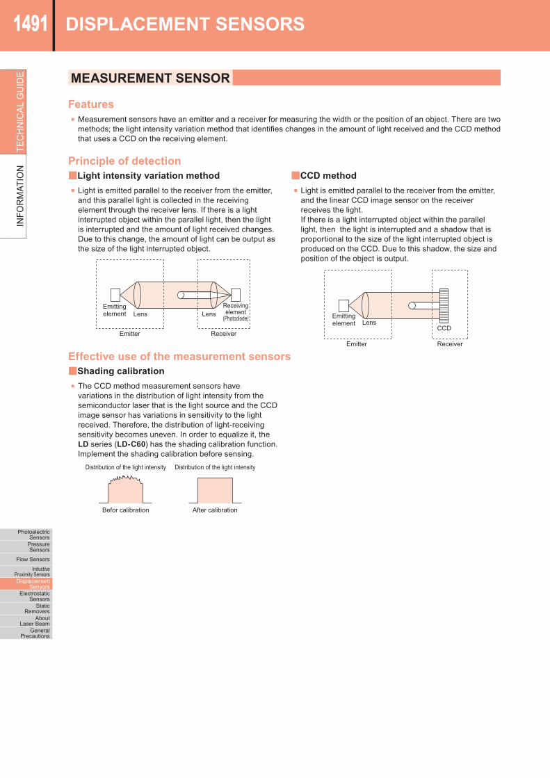
Features• Measurement sensors have an emitter and a receiver for measuring the width or the position of an object. There are two
methods; the light intensity variation method that identifies changes in the amount of light received and the CCD method that uses a CCD on the receiving element.
Principle of detection
• Light is emitted parallel to the receiver from the emitter, and this parallel light is collected in the receiving element through the receiver lens. If there is a light interrupted object within the parallel light, then the light is interrupted and the amount of light received changes. Due to this change, the amount of light can be output as the size of the light interrupted object.
Light intensity variation method• Light is emitted parallel to the receiver from the emitter,
and the linear CCD image sensor on the receiver receives the light.If there is a light interrupted object within the parallel light, then the light is interrupted and a shadow that is proportional to the size of the light interrupted object is produced on the CCD. Due to this shadow, the size and position of the object is output.
CCD method
Lens
Emitter Receiver
Emitting element
Receiving element
(Photodiode) Lens
Lens Emitting element
CCD
Emitter Receiver
Effective use of the measurement sensors
• The CCD method measurement sensors have variations in the distribution of light intensity from the semiconductor laser that is the light source and the CCD image sensor has variations in sensitivity to the light received. Therefore, the distribution of light-receiving sensitivity becomes uneven. In order to equalize it, the LD series (LD-C60) has the shading calibration function. Implement the shading calibration before sensing.
Shading calibration
Befor calibration
Distribution of the light intensity
After calibration
Distribution of the light intensity
1492DISPLACEMENT SENSORS
TEC
HN
ICAL
GU
IDE
INFO
RM
ATIO
NPhotoelectric SensorsPressure Sensors
Flow Sensors
Inductive Proximity SensorsDisplacement SensorsElectrostatic SensorsStatic RemoversAbout Laser BeamGeneral Precautions
EDDY CURRENT TYPE DISPLACEMENT SENSOR
Principle of detection• The eddy current type displacement sensors produce a
high-frequency magnetic field by applying a high-frequency current to the coil inside the sensor head. If there is a measurement object (metal) within this magnetic field, then excess current is produced around the magnetic flux that passes through the object surface due to the electromagnetic induction effect. This changes the impedance of the coil within the sensor head.The eddy current type displacement sensors measure the distance based on the change of the oscillation caused by this phenomenon.
High-frequency magnetic field
Eddy currents generate energy (thermal) loss due to the resistance of the metal, reducing the amplitude of oscillation.
Eddy current
Sensing object (metal)
Operation principles of the GP-X series and GP-A series• As the distance between the measurement object
(metal) and the sensor head becomes smaller, then greater excess current is produced and the loss of energy at the sensor head increases. As a result, when the distance is made closer, the oscillation becomes smaller. When the distance is greater, the oscillation becomes greater. The sensors rectify the variations in the oscillation and that causes a change of the DC voltage. The rectified signal is almost proportional to the distance. However, linearity is corrected through linearization and an output that is proportional to the distance can be obtained.
Far
Near
Sensor
Measuring object (Metal) Measuring object
Oscillation
Rectified signal
0 V
FarNear
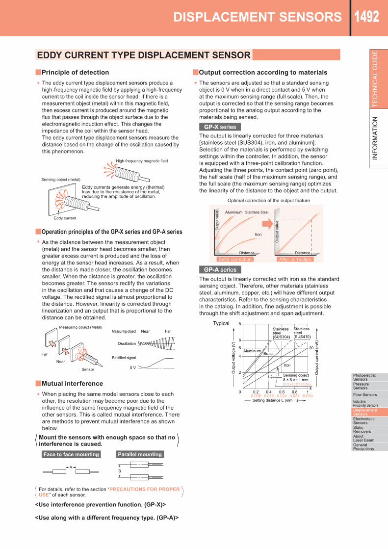
Output correction according to materials• The sensors are adjusted so that a standard sensing
object is 0 V when in a direct contact and 5 V when at the maximum sensing range (full scale). Then, the output is corrected so that the sensing range becomes proportional to the analog output according to the materials being sensed.
GP-X seriesThe output is linearly corrected for three materials [stainless steel (SUS304), iron, and aluminum]. Selection of the materials is performed by switching settings within the controller. In addition, the sensor is equipped with a three-point calibration function. Adjusting the three points, the contact point (zero point), the half scale (half of the maximum sensing range), and the full scale (the maximum sensing range) optimizes the linearity of the distance to the object and the output.
Distance
After correction Distance
Out
put v
alue
Out
put v
alue
Aluminum Stainless Steel
Iron
Befor correction
Optimal correction of the output feature
GP-A seriesThe output is linearly corrected with iron as the standard sensing object. Therefore, other materials (stainless steel, aluminum, copper, etc.) will have different output characteristics. Refer to the sensing characteristics in the catalog. In addition, fine adjustment is possible through the shift adjustment and span adjustment.
Typical
Setting distance L (mm in)
Out
put v
olta
ge (V
)
Out
put c
urre
nt (m
A)
0.20.008
0.40.016
0.60.024
0.80.031
10.039
0
2
4
6
205
4
8
AluminumBrass
Iron
Stainlesssteel(SUS304)
Stainlesssteel(SUS410)
L Sensing object 8 × 8 × t 1 mm0.315 × 0.315 × t 0.039 inMutual interference
• When placing the same model sensors close to each other, the resolution may become poor due to the influence of the same frequency magnetic field of the other sensors. This is called mutual interference. There are methods to prevent mutual interference as shown below.
Face to face mounting
A
Parallel mounting
B
For details, refer to the section “PRECAUTIONS FOR PROPER USE” of each sensor.
<Use interference prevention function. (GP-X)>
<Use along with a different frequency type. (GP-A)>
Mount the sensors with enough space so that no interference is caused.

1493 DISPLACEMENT SENSORSTE
CH
NIC
AL G
UID
EIN
FOR
MAT
ION
Photoelectric Sensors
Pressure Sensors
Flow Sensors
Inductive Proximity SensorsDisplacement
SensorsElectrostatic
SensorsStatic
RemoversAbout
Laser BeamGeneral
Precautions
GLOSSARY
Term Description
Resolution
When enlarging the linear output, there are minute fluctuations caused by noise inside the sensor even if an object is at rest. The width of this fluctuation is called resolution. When the width is smaller, the resolution is higher. In the digital signal process method, the measurement value is the minimum readable value. It is the minimum value that the device can indicate or that can be digitally output.
Linearity
The linear output of the displacement sensor is proportional to the amount of displacement. It is almost linear; but, there is a little gap between the actual line and the ideal line. Linearity indicates how large this gap is. This is also called linearity error.
Example: In case of 2 mm 0.079 in sensing type
2.00.079
1.00.039
0 2.00.079
1.00.039
Full scale
Maximum error
Ideal line
Setting distance (mm in)
Out
put v
olta
ge (V
)
Temperature characteristics
When the ambient temperature changes, the linear output also fluctuates. This fluctuation range is called temperature drift, and it indicates the value caused by changes of 1 °C 34 °F.For example, if 0.01 % F.S./°C is regarded as F.S. (Full Scale) = 10 V, it indicates that the fluctuation of 0.01 % of F.S. per 1 °C 34 °F, is 1 mV.
Spot diameter Optical displacement sensor
The spot diameter is generally defined to be 1/e2(13.5 %) of the sensor’s laser beam center light strength. There is light that leaks outside the defined range; therefore, if the reflective rate of the light is high compared to the area around the sensing point, influences may be exerted.
Measurement center distance Optical displacement sensor
This refers to the distance from the emitter front of the sensor to the center of the measuring range. The sensors with voltage output are the ones where the linear output voltage becomes 0 V at this time.