1539pk control of active power and frequency copyright © p. kundur this material should not be used...
TRANSCRIPT

1539pk
CONTROL OF ACTIVE POWER CONTROL OF ACTIVE POWER AND FREQUENCYAND FREQUENCY
Copyright © P. KundurThis material should not be used without the author's consent

1539pkC- 2
Active Power and Frequency ControlActive Power and Frequency Control
The frequency of a system is dependent on active power balance
As frequency is a common factor throughout the system, a change in active power demand at one point is reflected throughout the system
Because there are many generators supplying power into the system, some means must be provided to allocate change in demand to the generators
speed governor on each generating unit provides primary speed control function
supplementary control originating at a central control center allocates generation
In an interconnected system, with two or more independently controlled areas, the generation within each area has to be controlled so as to maintain scheduled power interchange
The control of generation and frequency is commonly known as load frequency control (LFC) or automatic generation control (AGC)

1539pkC- 3
Primary Speed ControlsPrimary Speed Controls
Isochronous speed governor
an integral controller resulting in constant speed
not suitable for multimachine systems; slight differences in speed settings would cause them to fight against each other
can be used only when a generator is supplying an isolated load or when only one generator in a system is required to respond to load changes
Governor with Speed Droop
speed regulation or droop is provided to assure proper load sharing
a proportional controller with a gain of 1/R
If precent regulation of the units are nearly equal, change in output of each unit will be nearly proportional to its rating
the speed-load characteristic can be adjusted by changing governor settings; this is achieved in practice by operating speed-changer motor

1539pkC- 4
ωr = rotor speed Y = valve/gate positionPm = mechanical power
Figure 11.7 Response of generating unit with isochronous governor
Figure 11.6 Schematic of an isochronous governor

1539pkC- 5
Figure 11.8 Governor with steady-state feedback
(a) Block diagram with steady-state feedback
(b) Reduced block diagram
Figure 11.9 Block diagram of a speed governor with droop

1539pkC- 6
Percent Speed Regulation or DroopPercent Speed Regulation or Droop
100x
100xchangeoutputpowerpercent
changefrequencyorspeedpercentRPercent
0
FLNL
whereωNL = steady-state speed at no loadωFL = steady-state speed at full loadω0 = nominal or rated speed
For example, a 5% droop or regulation means that a 5% frequency deviation causes 100% change in valve position or power output.
Figure 11.10 Ideal steady-state characteristics of a governor with speed droop

1539pkC- 7
Load Sharing by Parallel UnitsLoad Sharing by Parallel Units
1111 R
fPPP
2222 R
fPPP
1
2
2
1
R
R
P
P
Figure 11.12 Response of a generating unit with a governor having speed-droop characteristics
Figure 11.11 Load sharing by parallel units with drooping governor characteristics

1539pkC- 8
Control of Generating Unit Power OutputControl of Generating Unit Power Output
Relationship between speed and load can be adjusted by changing "load reference set point"
accomplished by operating speed-changer motor
Effect of load reference control is depicted in Figure 11.14
three characteristics representing three load reference settings shown, each with 5% droop
at 60 Hz, characteristic A results in zero output;characteristic B results in 50% output; characteristic C results in 100% output
Power output at a given speed can be adjusted to any desired value by controlling load reference
When two or more units are operating in parallel:
adjustment of droop establishes proportion of load picked up when system has sudden changes
adjustment of load reference determines unit output at a given frequency

1539pkC- 9
(b) Reduced block diagram of governor
(a) Schematic diagram of governor and turbine
Figure 11.13 Governor with load reference control
Figure 11.14 Effect of speed-changer setting on governor characteristic
1539pkC- 10
Composite System Regulating Composite System Regulating CharacteristicsCharacteristics
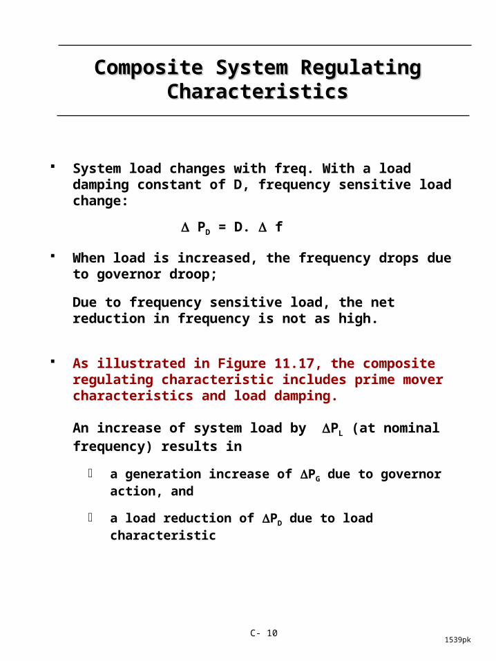
System load changes with freq. With a load damping constant of D, frequency sensitive load change:
PD = D. f
When load is increased, the frequency drops due to governor droop;
Due to frequency sensitive load, the net reduction in frequency is not as high.
As illustrated in Figure 11.17, the composite regulating characteristic includes prime mover characteristics and load damping.
An increase of system load by PL (at nominal frequency) results in
a generation increase of PG due to governor action, and
a load reduction of PD due to load characteristic

1539pkC- 11
The composite frequency response characteristic β is normally expressed in MW/Hz. It is also sometimes referred to as the stiffness of the system.
The composite regulating characteristic of the system is equal to 1/β
DR
P
DRRR
Pf
eq
L
n
LSS
1
111 21
where
DRf
P
RRRR
eqSS
L
neqeq
1
111
1
2
Figure 11.17 Composite governor and load characteristic

1539pkC- 12
Supplementary Control of Isolated Supplementary Control of Isolated SystemsSystems
With primary speed control, the only way a change in generation can occur is for a frequency deviation to exist.
Restoration of frequency to rated value requires manipulation of the speed/load reference (speed changer motor).
This is achieved through supplementary control as shown in Figure 11.22
the integral action of the control ensures zero frequency deviation and thus matches generation and load
the speed/load references can be selected so that generation distribution among units minimizes operating costs
Supplementary control acts more slowly than primary control.
This time-scale separation important for satisfactory performance.

1539pkC- 13
Figure 11.22 Addition of integral control on generating units selected for AGC

1539pkC- 14
Supplementary Control of Interconnected Supplementary Control of Interconnected SystemsSystems
The objectives of automatic generation control are to maintain:
system frequency within desired limits
area interchange power at scheduled levels
correct time (integrated frequency)
This is accomplished by using a control signal for each area referred to as area control error (ACE), made up of:
tie line flow deviation, plus
frequency deviation weighted by a bias factor Figure 11.27 illustrated calculation of ACE
Bias factor, B, set nearly equal to regulation characteristic (I/R + D) of the area; gives good dynamic performance
A secondary function of AGC is to allocate generation economically

1539pkC- 15
Figure 11.27 AGC control logic for each area

1539pkC- 16
Figure 11.28 Functional diagram of a typical AGC system

1539pkC- 17
Underfrequency Load SheddingUnderfrequency Load Shedding
Severe system disturbances can result in cascading outages and isolation of areas, causing formation of islands
If an islanded area is undergenerated, it will experience a frequency decline
unless sufficient spinning generation reserve is available, the frequency decline will be determined by load characteristics (Fig. 11.30)
Frequency decline could lead to tripping of steam turbine generating units by protective relays
this will aggravate the situation further
There are two main problems associated with underfrequency operation related to thermal units:
vibratory stress on long low-pressure turbine blades; operation below 58.5 Hz severely restricted (Fig. 9.40)
performance of plant auxiliaries driven by induction motors; below 57 Hz plant capability may be severely reduced or units may be tripped off

1539pkC- 18
Fig. 11.30 Frequency decay due to generation deficiency (L)
Fig. 9.40 Steam turbine partial or full-load operating limitations during abnormal frequency, representing composite worst-case limitations of
five manufacturers ©ANSI/IEEE-1987
1539pkC- 19
Underfrequency Load Shedding Underfrequency Load Shedding (cont'd)(cont'd)
To prevent extended operation of separated areas at low frequency, load shedding schemes are employed. A typical scheme:
10% load shed when frequency drops to 59.2 Hz
15% additional load shed when frequency drops to 58.8 Hz
20% additional load shed when frequency reaches 58.0 Hz
A scheme based on frequency alone is generally acceptable for generation deficiency up to 25%
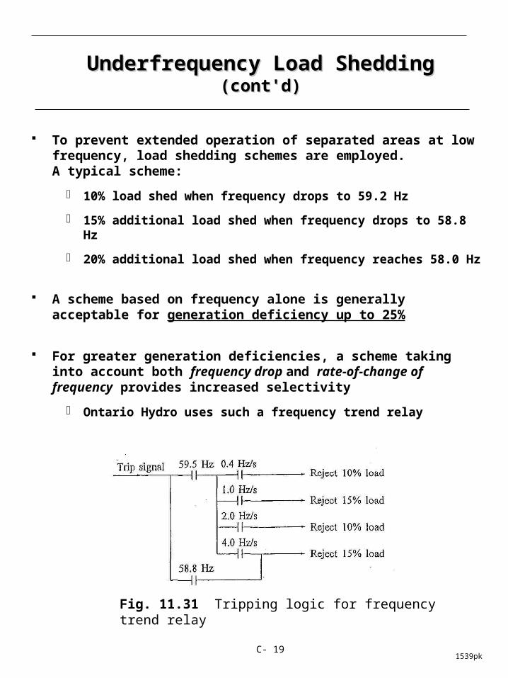
For greater generation deficiencies, a scheme taking into account both frequency drop and rate-of-change of frequency provides increased selectivity
Ontario Hydro uses such a frequency trend relay
Fig. 11.31 Tripping logic for frequency trend relay