155-mm artillery rearm module with liquid propellant, phase 1
TRANSCRIPT
AD-A280 213_U iAD
AD-E402 537
Contractor Report ARFSD-CR-94001
155-mm ARTILLERY REARM MODULE WITHLIQUID PROPELLANT, PHASE I
Matthew DiehlDavid Hoyt
Robert McLaneRichard Saganich
Stanley Turner
Francisco Velasquez ECTE flMartin Marietta "S J•1-•4U
Armament SystemsBurlington, VT 05401-4985
Wesley DeneryLalji Pavagadhi...
Project EngineersARDEC
June 1994
U.S. ARMY ARMAMENT RESEARCH, DEVELOPMENT ANDENGINEERING CENTER
Fire Support Armaments CenterWNW,• Picatinny Arsenal, New Jersey
•*OICAL AOMFMU C
Approved for public release; distribution is unlimited.
,-"94-18227"{~ ~~ ~~ u 4 13811 "IMIIIllll~lllill
The views. opinions, and/or findings contained in thisreport are those of the authors(s) and should not beconstrued as an official Department of the Army posi-tion. policy, or decision, unless so designated by otherdocumentation.
The citation In this report of the names of commercialfirms or commercially available products or services doesnot constitute official endorsement by or approval ofthe U.S. Government.
Destroy this report when no longer needed by any methodthat will prevent disclosure of its contents or recon-struction of the document. Do not return to the origi-nator.
REPORT DOCUMENTATION PAGE Form Approved OMB No. 0704013
Pub reporting burden for Mis olecion of InIormaUon Is mantled So average I hour per response. Includng ihe lie for reviewingb'stauctions. ojnto" exsting data sources, gathering and maund"ng te data needed. and compleing and reiewh the collecion ofInfonna8on. Send oomments regarding Ois burden elimale or any other aspect of this coliecion of information. induding suggestions forreducing mis burden. I* Wahington eHaiquarlers services Directorate Ior Infrmati•n pewaon and repormt. 1215 Jeferson DwisHighway. Suite 1204. Arlngtnn. VA Z202-4302. and to te Offc of Management and Budget. Psapework Reduction Prolet (0704-01U). Washington. DC 20503.1.A USEOL.(Ua * REPORT REPORT TYPE AND DATES COVERED
IJune 1994 Final I March 93 to August 93
4. TrILE AND SUBTITLE 5. FUNDING NUMBERS
155-mm ARTILLERY REARM MODULE WITH LQUID PROPELLANT. PHASE I DAAA21-93-G0032
&. AUTHUH(S)M. Diehl, D. Hoyt, R. McLane, R. Saganich, S. Turner, andF. Velasquez, Martin MariettaW. Denery and L. Pavagadhi, ARDEC Project Engineers
7. PERFORMING ORGANIZATION NAME(S) AND ADDRESSES(S) 8. PERFORMING ORGANIZATIONMartin Marietta ARDEC, FSAC REPORT NUMBERArmament Systems Artilery Armaments DivisionBurlington, VT 05401-4985 (SMCAR-FSA-F)
Picalinny Arsenal, NJ 07806-5000
9.SPONSORING&MONITORING AGENCY NAME(S) AND ADDRESS(S) 10. SPONSORING/MONITORINGAGENCY REPORT NUMBER
ARDEC, IMDSTINFO Br. (SMCAR-IMI-I) Contractor ReportPicatinny Arsenal. NJ 07806-5000 ARFSD-CR-94001
11. SUPPLEMENTARY NOTESThe Appendixes to Contractor Report ARFSD-CR-04001 e" included in a sepela l w1F Vie same respor number but fifferent AD-Enumber.
12L. DISTRIBUTIONAVAILABIUITY STATEMENT 12b. DISTRIBUTION CODE
Approved for public release: distribution is unlimited.
13. ABSTRACT (Maidmum 200 won s)
A summary of the concept study and preliminary design for an improved 155-mm artillery rearm module (ARM) ispresented. This module Is to be an Improvement over a 155-mm ARM designed, fabricated, and tested underprevious contract (DAAA21-88-C-0161). The trade-off study effort involving liquid propellant (XM46) handling andstorage concepts is discussed. The rearranging of the projectile handling magazines developed under previouscontract (DAAA21-91-C-0082) is also discussed. The preliminary design of the configuration selected on the basisof the trade study is presented.
14. SUBJECT TERMS 15. NUMBER OF PAGES
Automated resupply, 155-mm ammunition, Computerized ammunition selection, 99Liquid propellant, LGP1846, XM46, Artillery resupply, Ammunition storage
1 PRICE CODE
17. SECURITY CLASSIFICATION 18. SECURITY CLASSIFICATION 19. SECURITYCLASSIFICATIOI 20. UMITATION OF ABSTRACTOFFEPORT OFTHIS PAGE OFABSTRACT
UNCLASSIFIED UNCLASSIFIED UNCLASSIFIED SAR
NM 75W40012)a•0tdi Fam MS (Re. 2.40Pumfb byN09 &d 230-18
2M.1
CONTENTS
Page
Introduction I
Design Requirements 2
ARM II/LP System Definition 2Environmental Requirements 2Interface Requirements 3Physical Requirements 3Functional Requirements 3Performance Requirements 4Safety Requirements 4Human Factors Requirements 4
System Description 5
Electrical Control System 5Electronic Control Unit 5Motor Control 5Power Distribution Box 6Projectile Identification (Label Reader) 6LP Sensors and Actuators 6Conveyor Sensors and Actuators 8Projectile Magazine Sensors and Actuators 9Remote Handset 10Crew Station 10Maintenance Control Panel 11
LP Storage and Transfer System 12LP Transfer System 12LP Storage System 14LP Loading System 14
Accesion ForVehicle Interface ' For 15
NTIS CRA&IProjectile Storage System DTIC TAB 15
Bucket Carriers U;.announced 0 16Handoff Unit Jjstification ......... 16Drive Assembly 16
By .............................Conveyor System Di-t ibjtion 1 16
Handoff Conveyor 16Stub Conveyor Availability Codes 17Extendible Conveyor Avail a. ,d I or 17Docking Head Dist Special 17Drive Assembly 18Equilibrator t 18Load Tray 18Stow Receptacle 18
Surrogate Rearm Port 19
i
CONTENTS (cont)
Page
System Operation 19
System Deployment 19Vehicle Positioning 19Conveyor Deployment 20
LP Transfer 20Ol•erational Modes 20Maintenance Modes 23Emergency Procedures 24
Projectile Transfer 24Upload 24Download 25Auxiliary and Maintenance Functions 26
LP Study 26
Government/Contractor Agencies Visited 27
Subcontractors 28
Unknown LP Characteristics 28
Phase II LP Study Continuation Tests 29Centrifugal Pump Characterization Test 29Flexible Ho and Quick Disconnects 29System Simulation/Breadboard Test 29
LP System Analysis and Trade Studies 29
Piping and Pump Size Analysis 30
Pressure Drop Analysis for Temperature Extremes 30
Trade Studies 31Transfer Methods 31Storage Systems 31Pumps 32
Human Engineering and System Safety 32
Introduction 32
Background 33
Human Engineering Analysis 33Purpose 33Task Analysis Results 33
ii
CONTENTS (cont)
Page
System Safety Analysis 33
PHAResults 34
Summary of HE/SS Recommendations 34General 34Conveyor 35LP Handling/Storage 35Electronic Control 35
Phase II HE/SS Issues 36Vehicle Alignment for Docking 36Docking Head Handles/Controls 36HAZMAT Operations 37
Reliability 37
Mission/Failure Definition 37
Math Model/Block Diagram 38
System Requirement/Allocation 39
Trade Studies 39
Reliability Issues 39
Secondary Resupply Items 39
Operating Environment with LP 40
Conclusions 40
Recommendations 41
References 87
Distribution List 89
111ee
iv
TABLES
Page
1 Tradeoff matrix of available LP transfer methods 43
2 Tradeoff matrix of LP storage concepts 44
3 Tradeoff matrix for LP pump technology selection 45
4 Operational task analysis for ARM II/LP 46
5 Preliminary hazard analysis for ARM II/LP 50
V

vi
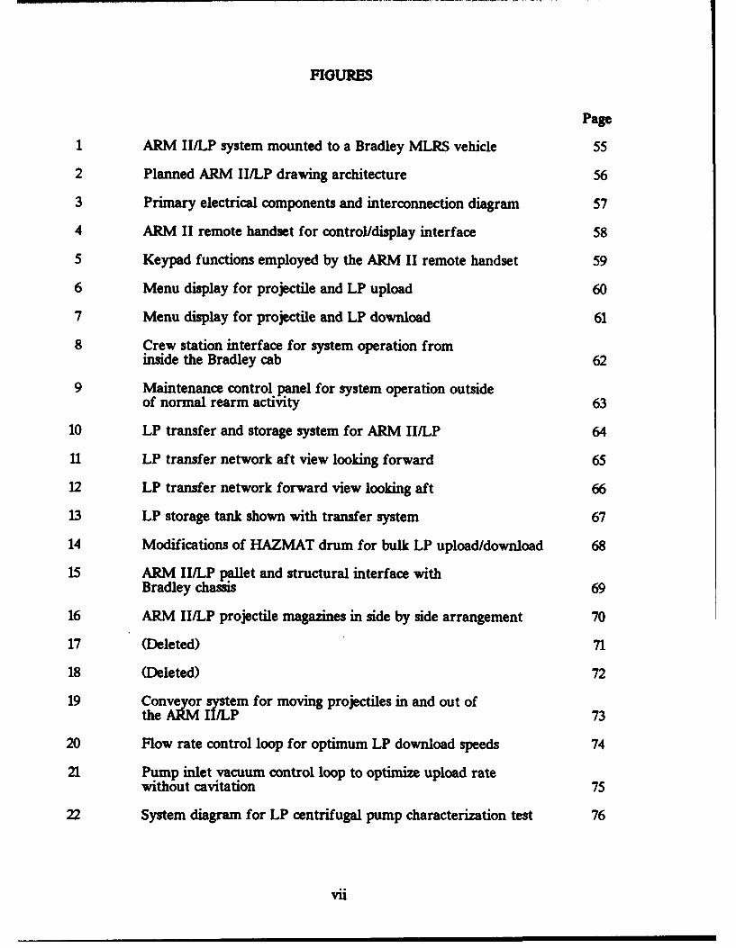
FIGURES
Page
1 ARM II/LP system mounted to a Bradley MLRS vehicle 55
2 Planned ARM II/LP drawing architecture 56
3 Primary electrical components and interconnection diagram 57
4 ARM II remote handset for control/display interface 58
5 Keypad functions employed by the ARM II remote handset 59
6 Menu display for projectile and LP upload 60
7 Menu display for projectile and LP download 61
8 Crew station interface for system operation frominside the Bradley cab 62
9 Maintenance control panel for system operation outsideof normal rearm activity 63
10 LP transfer and storage system for ARM II/LP 64
11 LP transfer network aft view looking forward 65
12 LP transfer network forward view looking aft 66
13 LP storage tank shown with transfer system 67
14 Modifications of HAZMAT drum for bulk LP upload/download 68
15 ARM II/LP pallet and structural interface withBradley chassis 69
16 ARM II/LP projectile magazines in side by side arrangement 70
17 (Deleted) 71
18 (Deleted) 72
19 Conveyor system for moving projectiles in and out ofthe ARM II/LP 73
20 Flow rate control loop for optimum LP download speeds 74
21 Pump inlet vacuum control loop to optimize upload ratewithout cavitation 75
22 System diagram for LP centrifugal pump characterization test 76
vii

FIGURES (cont)
Page
23 Pressure drop analysis for downloading to surrogate port 77
24 Centrifugal pump performance curves at variousimpeller speeds 78
25 NPSHa versus flow rate and line size for drawing LP outof a HAZMAT drum 79
26 Gravity feed flow rate during emergency dump for variousline sizes 80
27 Pressure map analysis for downloading to surrogate port 81
28 Pressure map for uploading from HAZMAT drums 82
29 Pressure map for uploading from surrogate port 83
30 Pressure map for downloading to HAZMAT drums 84
31 Hazard fault tree for ARM II/LP 85
32 ARM II/LP reliability block diagram 86
viii
INTRODUCTION
This document is the Phase I Final Report for the 155-mm Artillery Rearm Modulewith Liquid Propellant (ARM II/LP) program. This two phase program was awarded toGeneral Electric Armament Systems Department (GE-ASD), Burlington, VT on 11 March1993 by the U. S. Army Armament Research, Development and Engineering Center(ARDEC), and is sponsored and managed by PM-FARV, Picatinny Arsenal, NJ. GE-ASD,being a department of GE Aerospace which merged with Martin Marietta in April 1993, isnow Martin Marietta Armament Systems, which has assumed all assets and obligations ofGE-ASD including the ARM IIILP program.
The ARM II/LP program requires concept studies and subsequent development of aproof-of-principle artillery rearm module capable of deliftering both 155-mm projectilesand XM46 Liquid Propellant (LP) to a surrogate rearm port simulating a future fieldartillery system. The ARM II/LP ammunition delivery system is derived from the ARMII/Unicharge system currently under development by Martin Marietta forPM-AMMOLOG. The significant distinction between these two systems is that ARMI•/Urn will resupply projectiles and XM230 unicharge propellant whereas ARM II/LPwill resupply projectiles and LP. Both systems represent a second generation of artilleryresupply technology following the original ARM development (retroactively named ARMI) which successfully resupplied unfuzed 155-mm projectiles and 155-mm propellingcharges (cloth bag type in their steel container packaging).
Phase I - Concept Development is complete and covers a period from March 1993 toAugust 1993. This phase consisted primarily of an LP study and the formulation of apreliminary design approach. The findings of the LP study were used to guide thedevelopment of a safe and effective LP resupply concept, and are also documented in anunpublished report under separate cover. The recommended ARM II/LP conceptincludes:
- A single 250 gallon LP storage tank with a 50 gallon per minutecentrifugal pump and automated plumbing network.
- Two side-by-side independently driven projectile magazines with 1:1access and high speed search.- Electronic control system with software to operate the system andmanage cargo inventory.
- A 2-D matrix label reader automatic munition identification system.
- A manually deployed swing-out and extendible transfer conveyor withprecision docking head and integral LP coupling.
- A palletized structure for adapting the system to a Bradley MLRScarrier.
- A system for uploading LP from 30 gallon HAZMAT drums.
- A surrogate port to mate with the conveyor docking head and receive LPand projectiles for system demonstration.
The preliminary design for this concept was developed during Phase I and presentedat a Preliminary Design Review held at ARDEC on 29 July 1993.
Since mos of the non-LP portion of the ARM II/LP concept is similar or identicalto ARM II/Uni hardware, conceptual design of these components was unnecessary anddetail design, which is a Phase II activity, was authorized to proceed in parallel withPhase I. Specific Phase II detail design tasks initiated during this period were theprojectile magazines, non-LP electrical controls, munition identification, transferconveyor and vehicle interface structure.
DESIGN REQUIREMENTS
During Phase I of the ARM II/LP program, a list of system design requirementswas derived from the statement of work, prior ARM programs, customer requests andmission analysis. The system requirements were subsequently allocated to variouss-'bsystems and individual components through the process of functional decomposition.Near the end of Phase I, the requirements list was translated into a formal systemspecification, (Martin Marietta Specification #A10040), and submitted to fulfill therequirements of CDRL A023.
The following is a summary of the ARM II/LP system design requirements. Thecomplete system requirements specification is contained in the Prime Item DevelopmentSpecification (CDRL A023).
ARM II/LP System Definition
The ARM II/LP shall be a projectile and liquid propellant storage moduleproof-of-principle demonstrator for future field artillery rearm operations.
In a projectile upload operation, projectiles are manually placed onto the ARMII/LP transfer conveyor. The transfer conveyor shall carry the projectiles into the ARMII/LP where they shall be automatically identified and handed off to one of twoprojectile magazines.
In the manual projectile download operation, projectiles shall be automaticallyhanded off from the magazine to the transfer conveyor. The transfer conveyor shallbring the projectiles out of the ARM IIILP for manual removal. In the automaticprojectile transfer operation, the transfer conveyor shall deliver/accept 155-mm roundsto/from a surrogate rearm port.
Uploading LP into the ARM II/LP shall be accomplished by drawing LP fromHAZMAT supply drums into an onboard storage tank. Downloading LP to HAZMATdrums shall be accomplished through a combination of draining and/or pumping LP fromthe storage tank. Transferring LP between ARM II/LP and a surrogate port undergoingresupply or download, shall be accomplished by pumping LP to/from the storage tankthrough a flexible hose that is integral with the transfer conveyor. Control valves shallallow the same onboard pump to serve the uploading, downloading, and transferoperations.
ARM II/LP operation shall be under control of an electrical control system. Theelectrical control system shall also maintain onboard inventory information for bothprojectiles and LP.
The ARM IIILP shall utilize two projectile storage magazines mounted side by sideat the forward end of the Bradley MLRS M987 chassis bed. The LP storage module shallbe aft of the projectile storage module. The transfer conveyor shall be hinged at theforward end of the projectile storage module and shall swing outward, perpendicular tothe left side of the vehicle, during normal operation. For transport, the transfer
2
conveyor shall swing aft and stow against the left side of the system.
Environmental Requirements
1. The ARM II/LP shall be capable of meeting all operational performancerequirements when parked on terrain with up to 20% side slope and 20% grade. Inaddition, the system shall be transportable over terrain with up to 40% side slope and 60%grade.
2. The ARM II/LP shall meet all performance requirements with ambienttemperatures ranging from 320 to 125*F.
3. The ARM II/LP shall be resistant to water spray, sand, dust, rain, humidity,vibration, shock, solar radiation and electromagnetic radiation, as detailed in MartinMarietta Specification #A10040.
Interface Requirements
1. A M987 Bradley MLRS carrier chassis shall be used as the host vehicle for ARMII/LP.
2. For automated transfer the ARM II/LP shall interface with a surrogate port.
3. For manual transfer and projectile upload operations the ARM II/LP shallinterface with the ground, various existing cargo carriers and trucks, the existing selfpropelled Howitzer, and LP packaging (HAZMAT storage drums).
4. The ARM II/LP shall be capable of storing and transferring various 155-mmfuzed projectiles as properly combined and listed in the system specification.
5. Electrical input power shall be 24 volt DC as supplied by the Bradley auxiliarypower subsystem.
Physical Requirements
1. As a goal, the ARM II/LP empty weight shall not exceed 6,320 pounds.
2. Storage capacity shall be 60, 155-mm projectiles with fuzes and 250 gallons of LP,minimum.
3. Projectile orientation shall be such that they arn delivered to the surrogate portbase first.
Functional Requirements
1. The ARM II/LP system shall be capable of simultaneously transferring both LPand projectiles to the surrogate port at the rates specified, under all specifiedenvironmental conditions.
2. The ARM II/LP shall be capable of remote selection and automatic identificationof fuzes and projectiles, from coded labels, and shall maintain an inventory of onboardprojectiles and LP. The ARM II/LP shall automatically check for projectile/fuzecompatibility and provide an error indication if an incompatible projectile and fuzecombination is found.
3
3. In addition to the normal LP transfer modes of operation. the LP pumpingsystem shall provide for recirculation, draining, purging with water, and emergency dumpof all onboard LP to an external tank.
4. As a goal, the ARM II/LP pumping system shall be self priming. No manualhandling of containers of LP is allowed for priming. No external support equipment isallowed for priming.
Performance Requirements
1. Rearm time (for 60 projectiles and 250 gallons of LP) shall be five minutesmaximum; beginning when the docking head is connected and ending when the dockinghead is disconnected.
2. Projectile transfer rate (automated download) shall be 20 per minute for a fullload of one type, and 12 per minute for a full load of four mixed types. LP transfer rateshall be 50 gallons/minute, minimum.
3. LP upload from HAZMAT drums shall be accomplished in no more than 30minutes.
4. The ARM II/LP predicted mature system reliability shall be 8,000 mean roundsbetween failures (MRBF), minimum.
5. Scheduled maintenance shall be minimized. The design goal shall be to produce amodular system and provide adequate access for replacement of worn or failed items.
Safety Requirements
1. The operator/maintainer shall be protected from moving hardware, electricshock, pinch points, and exposure to chemicals.
2. The design shall be "fail safe" and shall provide built in test diagnostics tominimize secondary failures.
3. An emergency shower and eye wash station must be provided at all test locations.
4. Electrical components in contact with LP must be explosion proof.
5. A leak containment basin shall be provided for all portions of the LP systemexcept the conveyor. The basin shall have full system capacity.
6. Pressure relief valves shall be provided for LP plumbing and storage tankcomponents. Adequate provisions shall be installed in the LP hydraulic system to detectand arrest a fume off condition.
Human Factors Requirements
1. The ARM II/LP must be operable by a minimum of two and a maximum ofthree MOS 13B cannon crew members.
2. Operational lifting requirements are not to exceed 100 pounds.
4
SYSTEM DESCRIPTION
The ARM II/LP system concept consists of four major components; the projectilestorage system, the conveyor system, the LP storage and transfer system, and theelectrical control system; and is designed to mount on a Bradley MLRS carrier hostvehicle (fig. 1). The projectile storage system consists of two magazines positioned side byside at the forward end of the cargo area, with the projectiles oriented horizontally andnoses to the right. The transfer conveyor is cantilevered from the left forward corner ofthe left magazine, and is swung 90 degrees aft to stow alongside the system duringtransport. The LP storage and transfer system is located within a cabinet positioneddirectly behind the projectile magazines and is completely enclosed to protect theremainder of the system and the vehicle from potential spillage and leaks. The electricalcontrol system is located in an isolated compartment on the right side of the LP systemcabinet, and interconnects the vehicle, projectile magazines, conveyor, and LP system viawiring harnesses. All system components are mounted to a pallet structure, enabling theentire system to be installed and removed as a single unit. A vehicle interface structure isnested within the vehicle well to adapt the pallet to the vehicle.
Projectiles are uploaded by manually placing them onto the transfer conveyor,which then carries them to the projectile storage system where they are automaticallyidentified and handed off into the two magazines. LP is drawn from modified 30 gallonHAZMAT drums by running the pump at slow speed to upload the ARM II/LP storagetank. For demonstration purposes, projectiles and LP are downloaded through thetransfer conveyor docking head to a surrogate rearm port. Projectiles can -]so bedownloaded manually to pallets, truck beds and current Howitzers, and LL -an also bedownloaded back to HAZMAT drums.
The entire ARM IIILP system concept, as it existed at the end of Phase I, isdocumented on drawing 10051701 which was submitted as part -., CDRL A003 conceptualdesign drawings. Drawing 10051708 (fig. 2) depicts the planned d iwing architecture atthe end of Phase I, this drawing will be updated and expanded as the system detail designevolves.
Electrical Control System
The electrical control system is the set of electrical control boxes, motors, sensors,actuators, cables, human interface devices, and software required to provide an interfacewith the operator and to control the operation of the ARM II/LP mechanism. The majorcomponents of the electrical control system are described below and their interconnectionis illustrated in Figure 3.
Electronic Control Unit
The electronic control unit contains the system microprocessor and itsinterfaces to the rest of the control system. This urnt will be made up of a collection ofprinted circuit boards and a chassis which have been designed and used on other products.This approach will provide a controller with excess capacity to adapt to anticipatedchanges in the requirements as the system design progresses, and the use of provenhardware will reduce the risk and cost of this portion of the program.
The processor circuit card assembly contains the MIL-STD-1750 micro-processor and its system interfaces. The memory circuit card assembly contains thecomputer memory, including the read only memory (ROM) for program storage, therandom access memory (RAM) for temporary storage, and the electrically erasableprogrammable read only memory (EEPROM) for nonvolatile data storage. The discrete
5
input circuit card assembly contains interfaces to discrete sensors with on/off signals suchas switches. The discrete output circuit card assembly contains interfaces to discreteindicators and actuators which require an on/off signal. The analog I/O circuit cardassembly contains the interfaces to the magazine position synchros and LP analog sensors,and produces the analog rate commands to the motor control. The serial communicationscircuit card assembly contains the serial interfaces to the handsets and the label reader.
Motor Controls
The motor controls will be similar to the existing ARM II/Uni digital servoamplifier. The servo low level electronics will be packaged within the power distributionbox. High level units 1 and 2 will contain the servo power amplifiers. The motor controlcircuits will take analog rate control signals from the electromc control unit and ratefeedback signals from the motor tachometers and provide the power control capability todrive the motors at the commanded speeds.
ARM II/LP has four motors under rate control, each with a separatecontroller. There is one rate controlled motor for each projectile magazine, one for theLP pump, and one for the conveyor.
The motor controls will be packaged so as to survive in the envir. ,ntswhich ARM II/LP is expected to be subjected with special emphasis on temperature andheat dissipation.
Power Distribution Box
The power distribution box controls the switching of power to the variou-system components, the sensing and interruption of overloads, and the interruption ofhigh level power when an emergency stop switch is pressed. The servo low levelelectronics is also packaged within the power distribution box.
Projectile Identification (Label Reader)
Projectile Label Data. The projectile label will contain: the national stocknumber (13 digits, example 1230009368278); the lot number (up to 15 alphanumericcharacters, example JFH83F874-298); the projectile weight (up to 6 numeric string,example 101.28); and a condition code (1 alphanumeric character).
Fuze Label Data. The fuze label will contain: the national stock number (13digits); the lot number (up to 15 alphanumeric characters); and a condition code (1alphanumeric character).
Performance. The label reader will utilize the same 2/D matrix technologyutilized on the ARM II/Uni program. The label reader is a fixed scanner which readsencoded labels as the projectile (with or without fuze installed) moves through itsscanning range. The information is automatically read with the projectile/fuze in anyanFular position (about the projectile center line). A multiple number of labels areprinted onto an adhesive band which is wrapped around the projectile body and fuze
ousing. If the identification label is missing or unreadable on the projectile or fuze, or ifthe fuse is absent, the projectile will be loaded and "unknown" will be recorded inmemory for the projectile and/or the fuze.
LP Sensors and Actuators
In addition to the LP pump motor, the following sensors and actuators are
6
included on the LP subsystem.
Motor Controlled Valves. A combination of five motor controlled valvesprovide control of LP flow within the LP subsystem. Limit switches on the valves willpovide the electronic control unit with feedback of valve positions. Valve positions willbe set as a function of operating mode, and correct position verified prior to operation ofthe pump.
HAZMAT Port Solenoid Valve. To provide fail safe closure of the HAZMATport. a spring return solenoid valve will be utilized to enable flow through the HAZMATport.
Priming Pump. A priming pump provides a means of priming the systemwhen the LP level falls below the LP pump s priming well level. The priming pump iscontrolled via a switch on the maintenance control panel.
Tank Low and High Level Switches. Level switches are provided at the lowand high tank levels to ensure that pump operation is inhibited beyond the limits of thetank. The low level is the zero reference for tank inventory control. The level switchesutilize an optical refraction technology to detect the LP fluid level.
Drum Level Sensor. The drum level sensor data is utilized by the electroniccontrol unit to prevent over filling HAZMAT drums during a download or drawing airinto the LP system from an empty HAZMAT drum while uploading. The drum levelsensor utilizes ultrasonic technology to sense the LP level in the drum.
Level Sensor. The LP inventory is monitored by a level sensor in the tankwhich utilizes the RF admittance principle. The quantity of LP transferred is determinedby the difference in measurements before and after the transfer is complete and all tankturbulence has settled.
Flow Meter. The flow rate of LP during pumping is monitored by the flowmeter utilizing magnetic inductive flow sensing technology. The flow data is integrated tomonitor volume transferred while pumping is in process to determine the correct pumpshut-off point for the desired transfer volume. The flow data is also used as the feedbacksignal for the flow rate control loop used during LP download modes.
Pump Inlet Pressure Sensors. In upload modes of operation, the pumpcontrol loop will maintain a constant vacuum at this sensor location. If vacuum exceedsthe control loops ability to maintain control, the upload will be interrupted and a pluggedline or empty rum condition will be assumed. If the data collection mode is active, thisdata will be reported to an external recording device via the test RS-232 port.
Docking Head Interlock Switch. The docking head interlock switch will beutilized to prevent the system from entering LP modes using the docking head untildocking is complete.
Surrogate LP Ready Sensor. The surrogate LP ready sensor will interlock allupload and download of LP via the conveyor until the surrogate system is ready fortransfer. A magnetic reed switch will be utilized to sense a magnetic field generated bythe surrogate port when it is ready for transfer.
Audio Alarm. A two tone audio alarm will alert the crew of any hazardouscondition detected. The alarm will be activated according to the emergency procedures.The alarm will have two different sounds indicating a level 1 or level 2 emergency.
7
Visual Alarm. A visual alarm will alert the crew of any hazardous conditionduring a level 1 or 2 emergency.
LP liquid Sensor. Presence of LP in the drip basin will initiate a level I alarmcondition.
Smoke Sensor. An ionization smoke detector will be located in the LP tankvent to detect a LP fuming condition. Detection will cause the electronic control unit tohalt all pump operations, set valves, and activate alarms as specified in the emergencyprocedures. If the ARM II/LP system is off, the smoke detector will activate level 1alarms via system battery power.
Tank Temperature Switch. The tank temperature switch will activate thelevel 1 alarms via battery power if excessive tank temperature is detected.
Temperature Sensors. Temperature sensors are located at the pump outlet,pump inlet, pump priming well, tank bottom, tank middle, tank top, and each of threetrapped pipe sections between potentially closed valves. If a temperature is greater than180.F, pump operation will be software inhibited, and valves and alarms will be set asdefine in the emergency procedures. If data collection mode is active, data will bereported to an external recording device via the test RS-232 port.
Pressure Sensors. Pressure sensors are located at the pump outlet port andtrapped pipe sections between potentially closed valves. If a pressure is detected greaterthan 80 psi, pump operation will be software inhibited, and valves and alarms will be setas defined in the emergency procedures. If data collection mode is active, data will bereported to an external recording device via the test RS-232 port.
Conveyor Sensors and Actuators
In addition to the conveyor drive motor, the following sensors and actuatorsare included on the conveyor subsystem.
Resolver. The conveyor resolver provides absolute position of the conveyorwhich is utilized to control the positioning of projectiles in preparation for transfer to theprojectile magazines.
Initial Timing. During an upload operation the position of the projectile onthe conveyor must be sensed just prior to entering the magazine handoff so that theconveyor and the projectile location can be synchronized with the conveyor resolver data.At the conveyor rate required to meet system transfer rate requirements the conveyormust be slowed to a stop in a controlled, ramp down, manner to prevent over shootingthe desired position. The initial timing sensor utilizes an optical beam technology as isused in the ARM II/Uni system.
Limit 1 and Limit 2 Sensors The conveyor will contain two pairs of limitsswitches utilized to ensure proper positioning of projectiles prior to transfer into eitherprojectile magazine. For proper positioning, the base of the projectile must be past thelimit 1 sensor and covering the limit 2 sensor. All limit sensors will utilize optical beamsensor technology as utilized on the ARM II/Uni system.
Collision Avoidance and Load Tray Sensors. During a download operationwhen a projectile is left on the conveyor load tray and another projectile is approachingon the conveyor, the conveyor will be stopped to prevent a collision between the twoprojectiles. To control this function a mechanical switch is built into the load tray
8
support so that it is actuated when there is weight on the load tray. Another sensor willbe located on the conveyor between the conveyor belts to sense an approaching projectile.The collision avoidance sensor will be a proximity switch sensing the metal surface of theprojectile as it passes over the sensor.
Projectile Orientation Sensor. During the upload operation, when projectilesare manually loaded on the conveyor, human error allows for the possibility that theprojectiles will be loaded in the wrong orientation, base first vs nose first. A reversedprojectile would not be sensed and positioned properly and could cause damage to thesystem or the projectile. The projectile orientation sensor is a proximity sensor locatedjust ahead of the initial timing sensor. If the projectile is nose first, the initial timingsensor optical beam will be broken by the nose of the projectile before the projectilesurface is close enough to the projectile orientation sensor to be detected. If the projectileis base first the projectile orientation sensor will sense the projectile base before theinitial timing optical beam is broken by the base.
Grommet Sensor. The ARM IIILP system is not capable of handlingprojectiles with grommets in place. To prevent damage due to operator error, thegrommet sensor will detect the presence of grommets, halting the conveyor so theprojectile can be removed and prepared for upload. The grommet sensor employesoptical beam technology to detect the increased diameter of the projectile at the grommet.
Fuze Camera Trigger. The fuze ID camera will be triggered by the fuzecamera trigger when the tip of the fuze breaks the triggers optical beam.
Conveyor Interlock Switch. A switch will be built into the conveyordeployment mechanism which will be utilized to prohibit operation of the conveyor unlessit is fully deployed.
Emergency Stop Switches. The emergency stop switches provide the crew witha means to stop the (motor/conveyor) system in the event of any immediate or potentialhazard to personnel or system hardware. Actuation of the emergency stop requires onlya simple depression which locks the switch in a depressed position. Restarting the systemafter an emergency stop can only be initiated by retracting the same emergency stopswitch that created the stop, and will require additional protocols (procedural verificationthat conditions are safe to restart the system), which are implemented and prompted viathe remote handset. These safety switches are located at six positions on the conveyor,one in the crew station, and one on the maintenance panel.
Projectile Magazine Sensors and Actuators
In addition to the magazine drive motor, the following sensors and actuatorsare included on each projectile magazine.
Magazine Resolvers. The magazine position sensors include a synchronizerattached to eac magazine in such a manner that it will rotate through one revolution as amagazine element moves through one complete cycle of the serpentine loop. The synchrooutput will be sent to the processor through a synchro to digital converter and will beused for magazine timing as well as identification of magazine elements for inventorycontrol purposes.
Empty Element Sensors. The empty element sensor will sense the presence ofa projectile in a magazine element. It will be used as a double check of the inventoryinformation to prevent loading a projectile into an already full magazine element. Forthis purpose an inductive proximity switch will be used. This sensor will be located as
9
close as possible to the projectile load position to minimize timing delays.
Magazine Transfer Solenoid. This actuator will initiate the action of themagazine transfer forks and selector gate to load a projectile into or out of the magazine.The movement and timing of this transfer mechanism will be mechanically controlled anddriven from the magazine motion.
Gate Interlocks. Data from the gate interlock sensors will be utilized toinhibit automatic operation when the transfer mechanism is manually activated toprevent mechanical damage to the system.
Remote Handset
The remote handset (RH) is the primary user interface with the ARM II/LPsystem. As shown in figure 4, the remote handset provides a control/display interfacecomprised of a (3 in. x 5 in.) liquid crystal display (LCD) and a numeric! control-functionkeypad. The LCD is an array of 240 horizontal by 128 vertical pixels formatted toprovide 16 lines of text/symbols using 40 (5x7) characters per line. Line graphics, blinkingand inverse video attributes are also supported. The dedicated function keypad provideslocal display controls (SCROLL and PAGE), system loic controls (TAKE CONTROL.MAIN MENU, CLEAR ENTRY. and ENTER). numeric data entry (0-9. CLEAR) andsystem-level controls (START and STOP). These keypad functions are described in figure5.
The display area is formatted such that the arrangement of information isconsistent, regardless of the application (upload, download, menu selections, etc). Thedislay arrangement shown in figures 6 and 7 is representative of all of the primaryupload/download displays. The display areas common to all of these applications include(as a minimum):
- Menu or operational task title, centered at the top of the display.
- Menu options/data field area in the central area.
- Procedure/prompt/message area at the bottom.
- Reserved area in the upper left for the CONTROL indication.
- Single line cursor box including a caret (>) symbol to designatea selected menu option or a selected munition.
Crew Station
The crew station interface (fig. 8) is dash mounted within the Bradley chassiscab at a location between the driver and passenger positions. This unit includes anenclosure/mounting assembly that contains:
- A power ON toggle switch and indicator.
- An emergency stop switch.
- A level I alarm override switch.
- A (removable) remote handset.
10
The function of the crew station is to provide power control for the ARMII/LP system, an emergency stop capability and the ability to interrogate and/or make(limited) data entries to the ARM system. The rationale for locating this ARM interfacein the vehicle cab is to enable the following in-route capabilities:
- To expedite the download process by allowing the order to be enteredprior to arrival and system deployment.
- To allow interrogation of current inventories to provide information toother resupply, transport, command or user elements.
- To conduct built-in-test (BIT) or assess/coordinate maintenance needsfor use at a later time/destination.
Maintenance Control Panel
The maintenance control panel (fig. 9) is not intended for use during normalupload/download operations. The function of this set of controls is to facilitate certainmaintenance operations and to coordinate certain degraded (download) mode operationswhere a transfer (or total) power loss has been experienced. This panel contains thefollowing controls which will be functionally described below.
Auto-Manual Mode Control. This toggle switch will normally be in the AUTOposition for routine system operation. In the MANUAL position, this control enables theremaining maintenance control panel functions and inhibits system control from the crewstation or remote handset.
Mode Selection. This three position rotary switch allows the selection ofeither of the two projectile magazines or the LP system. Only the selected magazine orthe LP system wifl operate as dictated by the remaining controls.
Conveyor Enable. This switch will enable the conveyor along with theselected magazine in either of the magazine modes.
Conveyor Manual Direction. This three-position toggle switch determines thedirection of operation (upload, download, center off) of the conveyor and selectedmagazine.
Rate Control. This rotary switch controls the system magazine and conveyorrates (MANUAL mode) and the cyclic rate through the system computer (AUTO mode).
Manual Rate Fine Adjust. This variable control allows for fine adjustment ofsystem magazine and conveyor rates in manual mode.
LP Drain Enable. This switch will set all valves to the LP system gravitydrain position when the LP mode is selected.
Well Full Indicator. This indicator will illuminate when the LP pump is fullindicating that the priming function is complete.
pressed- Priming Pump. This momentary switch will activate the priming pump while
Emergency Stop. This control is physically and functionally identical to theother eight emergency stop switches located throughout the system.
11
Error Indicator. This indicator will illuminate whenever the system hasidentified an error condition such as a reversed projectile, activated emergency stop, etc.
Alarm Override. This switch allows the crews to turn off the audio alarm inthe event of a false level I emergency in the LP system.
Security. All of the maintenance control panel switches, push-button, etc.,except for the emergency stop, will be physically secured (via a front cover panel) andkey switch to prevent unauthorized, unintentional, or otherwise undesirable operationthat might be unsafe or in contention with normal system operation.
LP Storage and Transfer System
The selected concept for the transfer and storage of LP is a pumping system with asingle storage tank. The pumping system consists of a variable speed, centrifugal pumpwith typically 1.5 in. diameter plastic piping and motor driven valves. Operating speedsare relatively low. The surrogate rearm port contains a simplified version of the LP
system and includes a storage tank, a flexible hose, and plastic piping and valves.
Pressure transducers, temperature sensors, and relief valves are located in eachpotentially pressurized section of plumbing and are constructed of various compatiblestainless steels, elastomers, and plastics. A single storage tank, made of polyethylene,offers the simplest mechanization approach and includes several safety features.
The LP system also includes provisions to contain any inadvertent LP spillageand/or personnel exposure due to leaks or pipe bursts. To that end, the tank, pump, andplumbing are surrounded by an enclosure which includes a containment basin beneath theLP system. Figure 10 shows the LP transfer and storage system.
LP Transfer System
The LP transfer system consists of the LP pump and the entire plumbingnetwork needed to interconnect the LP storage tank. the surrogate rearm port, and theLP loading system. Components are predominantly of non-metallic construction. LPflow is controlled by motorized ball valves. Within the transfer system a recirculationline allows air purging and system checkout prior to LP delivery, and drain lines providefor complete system purging. An emergency dump line with a motorized valve will allowthe rapid offloading of LP to a controlled external storage tank for dilution and coolingin the event of a fume-off within the storage tank.
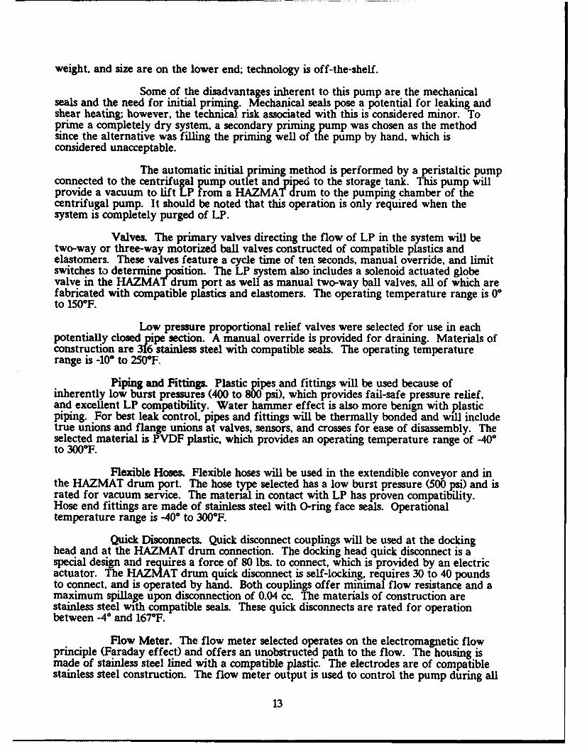
A secondary pump is used for initial system priming or for re-primingwhenever the main pump has been drained for maintenance. Pressure relief valves aswell as pressure an temperature sensors will be utilized in each potentially closed pipesection. In the unlikely event that a LP reaction should initiate within the plumbing, afinal pressure relief is provided by the plastic piping which will burst at about 600 psi. Anormally closed solenoid valve at the HAZMAT drum port will prevent LP spillagethrough the HAZMAT drums in the event of power loss. The L transfer system isshown in figures 11 and 12.
Pumps. A self-priming centrifugal pump with stainless steel wetted parts andmechanical shaft seals is selected as baseline for the ARM II/LP system. The pump andimpeller size will provide a flow rate of at least 50 gpm and an outlet pressure ofapproximately 35 psi. The selection of a centrifugal pump was based on the lower risk ofadiabatic compression as compared to positive displacement pumps; ability to operate dry;and temperature compatibility with ARM II/LP as well as FARV requirements. Cost,
12
weight, and size are on the lower end; technology is off-the-shelf.
Some of the disadvantages inherent to this pump are the mechanicalseals and the need for initial priming. Mechanical seals pose a potential for leaking andshear heating; however, the technical risk associated with this is considered minor. Toprime a completely dry system, a secondary priming pump was chosen as the methodsince the alternative was filling the priming well of the pump by hand, which isconsidered unacceptable.
The automatic initial priming method is performed by a peristaltic pumpconnected to the centrifugal pump outlet and piped to the storage tank. This pump willprovide a vacuum to lift LP from a HAZMAT drum to the pumping chamber of thecentrifugal pump. It should be noted that this operation is only required when thesystem is completely purged of LP.
Valves. The primary valves directing the flow of LP in the system will betwo-way or three-way motorized ball valves constructed of compatible plastics andelastomers. These valves feature a cycle time of ten seconds, manual override, and limitswitches to determine position. The LP system also includes a solenoid actuated globevalve in the HAZMAT drum port as well as manual two-way ball valves, all of which arefabricated with compatible plastics and elastomers. The operating temperature range is 0Oto 150°F.
Low pressure proportional relief valves were selected for use in eachpotentially closed pipe section. A manual override is provided for draining. Materials ofconstruction are 316 stainless steel with compatible seals. The operating temperaturerange is -10° to 250"F
Piping and Fittings. Plastic pipes and fittings will be used because ofinherently low burst pressures (400 to 800 psi), which provides fail-safe pressure relief,and excellent LP compatibility. Water hammer effect is also more bemgn with plasticpiping. For best leak control, pipes and fittings will be thermally bonded and will includetrue unions and flange unions at valves, sensors, and crosses for ease of disassembly. Theselected material is PVDF plastic, which provides an operating temperature range of -400to 300°F.
Flexible Hoses. Flexible hoses will be used in the extendible conveyor and inthe HAZMAT drum port. The hose type selected has a low burst pressure (500 psi) and israted for vacuum service. The material in contact with LP has proven compatibility.Hose end fittings are made of stainless steel with 0-ring face seals. Operationaltemperature range is -400 to 300°F.
Quick Disconnects. Quick disconnect couplings will be used at the dockinghead and at the HAZMAT drum connection. The docking head quick disconnect is aspecial design and requires a force of 80 lbs. to connect, which is provided by an electricactuator. The HAZMAT drum quick disconnect is self-locking, requires 30 to 40 poundsto connect, and is operated by hand. Both couplings offer minimal flow resistance and amaximum spillage upon disconnection of 0.04 cc. The materials of construction arestainless steel with compatible seals. These quick disconnects are rated for operationbetween -4 and 167*F.
Flow Meter. The flow meter selected operates on the electromagnetic flowprinciple (Faraday effect) and offers an unobstructed path to the flow. The housing ismade of stainless steel lined with a compatible plastic. The electrodes are of compatiblestainless steel construction. The flow meter output is used to control the pump during all
13
download modes. Operating temperature range is compliant with expected FARVrequirements.
Sensors. Temperature and pressure sensors will be utilized in each potentiallyclosed pipe section as well as in the pump inlet and outlet. A pressure transducer in thepump inlet will monitor suction pressure for regulating the pump speed during uploadoperations. A temperature sensor and a level indicator will also be placed in the pump.The temperature sensors are conventional thermocouples made of compatible materials.The pressure transducers are electronic variable capacitance sensors with LP compatiblewetted components. The level indicator is an electro optic liquid level sensor withvariable delay time drop-out and is LP compatible. All selected sensors satisfy expectedFARV temperature requirements.
LP Storage System
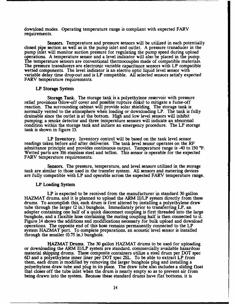
Storage Tank. The storage tank is a polyethylene reservoir with pressurerelief provisions (blow-off cover and possible rupture disks) to mitigate a fume-offreaction. The surrounding cabinet will provide solar shielding. The storage tank isnormally vented to the atmosphere when loading or downloading LP. The tank is fullydrainable since the outlet is at the bottom. High and low level sensors will inhibitpumping; a smoke detector and three temperature sensors will indicate an abnormalcondition within the storage tank and initiate an emergency procedure. The LP storagetank is shown in figure 13.
LP Inventory. Inventory control will be based on the tank level sensorreadings taken before and after deliveries. The tank level sensor operates on the RFadmittance principle and provides continuous output. Temperature range is -40 to 150 *F.Wetted parts are 316 stainless steel and teflon. This sensor is operable for the expectedFARV temperature requirements.
Sensors. The pressure, temperature, and level sensors utilized in the storagetank are similar to those used in the transfer system. All sensors and metering devicesare fully compatible with LP and operable across the expected FARV temperature range.
LP Loading System
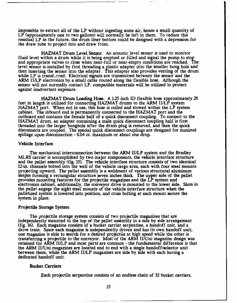
LP is expected to be received from the manufacturer in standard 30 gallonHAZMAT drums, and it is planned to upload the ARM II/LP system directly from thesedrums. To accomplish this, each drum is first altered by installing a polyethylene drawtube through the larger (2 in.) bunghole. Immediately prior to transferring LP, anadapter containing one half of a quick disconnect coupling is first threaded into the largebunghole, and a flexible hose containing the mating coupling half is then connected to it.Figure 14 shows the additions and modifications necessary for bulk upload and downloadoperations. The opposite end of this hose remains permanently connected to the LPsystem HAZMAT port. To complete preparations, an acoustic level sensor is installedthrough the smaller (0.75 in.) bunghole.
HAZMAT Drums. The 30 gallon HAZMAT drums to be used for uploadingor downloading the ARM II/LP system are standard, commercially available hazardousmaterial shipping drums. These composite containers utilize a steel drum per DOT spec6D and a polyethylene inner liner per DOT spec 2SL. To be able to extract LP fromthem, each drum is modified by removing the larger bunghole plu$ and installing apolyethylene draw tube and plug in its place. The draw tube also includes a sliding floatthat closes off the tube inlet when the drum is nearly empty so as to prevent air frombeing drawn into the system. Because these standard drums have flat bottoms, it is
14
impossible to extract all of the LP without ingesting some air, hence a small quantity ofLP (approximately one to two gallons) will normally be left in them. To reduce thisresidual LP in the future, the drum liner bottom could be designed with a depression forthe draw tube to project into and draw from.
HAZMAT Drum Level Sensor. An acoustic level sensor is used to monitorfluid level within a drum while it is being emptied or filled and signal the pump to stopand appropriate valves to close when near-full or near-empty conditions are reached. Thelevel sensor is installed by first threading a plastic adapter into the smaller bung hole andthen inserting the sensor into the adapter. This adapter also provides venting of the drumwhile LP is transf,.-rred. Electrical signals are transmitted between the sensor and theARM II/LP electronics by a small cable routed along the flexible hose. Although thesensor will not normally contact LP, compatible materials will be utilized to protectagainst inadvertent exposure.
HAZMAT Drum Loading Hose. A 1.25 inch ID flexible hose approximately 20feet in length is utilized for connecting HAZMAT drums to the ARM II/LP systemHAZMAT port. When not in use, this hose is coiled and stowed within the LP systemcabinet. The inboard end is permanently connected to the HAZMAT port and theoutboard end contains the female half of a quick disconnect coupling. To connect to theHAZMAT drum, an adapter containing a male quick disconnect coupling half is firstthreaded into the larger bunghole after the drum plug is removed, and then the quickdisconnects are coupled. The special quick disconnect couplings are designed for minimalspillage upon disconnection - 0.04 cc. maximum or about one drop.
Vehicle Interface
The mechanical interconnection between the ARM II/LP system and the BradleyMLRS carrier is accomplished by two major components, the vehicle interface structureand the pallet assembly (fig. 15). The vehicle interface structure consists of two identical12-in. channels bolted into the well of the vehicle cargo area, each with four steel mountsprojecting upward. The pallet assembly is a weldment of various structural aluminumshapes forming a rectangular structure seven inches thick. The upper side of the palletprovides mounting features for the projectile magazines and the LP system andelectronics cabinet, additionally, the conveyor drive is mounted to the lower side. Slots inthe pallet engage the eight steel mounts of the vehicle interface structure when thepalletized system is lowered into position, and cross bolting at each mount secure thesystem in place.
Projectile Storage System
The projectile storage system consists of two projectile magazines that areindependently mounted to the top of the pallet assembly in a side by side arrangement(fig. 16). Each magazine consists of a bucket carrier serpentine, a handoff unit, and adrive train. Since each magazine is independently driven and has its own handoff unit,one magazine is able to search for a desired projectile at high speed while the other istransferring a projectile to the conveyor. Most of the ARM II/Uni magazine design wasretained for ARM II/LP and most parts are common - the fundamental difference is thatthe ARM II/Uni magazines are located end to end with a single handoff/selector unitbetween them, while the ARM II/LP magazines are side by side with each having adedicated handoff unit.
Bucket Carriers
Each projectile serpentine consists of an endless chain of 32 bucket carriers,
15
each carrier fully restraining the round under normal operating conditions to eliminatefriction with guide surfaces within the magazine. Because of the side by side magazinearrangement, the two serpentines are identical, whereas in the ARM II/Uni magazines theforward serpentine is opposite hand from the aft serpentine. At the handoff unit,projectiles are snapped into or out of the carriers.
Handoff Unit
The two identical ARM II/LP handoff units, one for each magazine, aresimilar to the single bi-directional ARM II/Uni handoff/selector unit except all partsassociated with the forward magazine handoff have been deleted. Additionally, the twohandoff unit side plates are redesigned and an end panel added to facilitate enclosing theforward end of each magazine.
Drive Assembly
The serpentines and handoff mechanisms of each projectile magazine aredriven by an identical, independently operated drive system consisting of a motor, speedreducer and gear train. This portion of the projectile storage system is identical to theARM II/Uni drive system.
Drive power is provided by a commonly used 28 volt DC electric motor, whichcan deliver 2.5 HP continuous at 5000 RPM with a 130 amp current draw. This maximumspeed will be applied for short duration high speed search, with a commercially availablespeed reducer providing the necessary reduction to drive the serpentine at 80 rounds perminute. Most of the time the drive motor will operate at 1250 RPM, corresponding to 20rounds per minute.
Conveyor System
The transfer conveyor system consists of four distinct interconnected conveyors(handoff, stub, extendible, and docking head) which together provide the means totransport projectiles between the ARM II/LP storage magazines and the future Howitzer,which is to be represented by a surrogate rearm port for ARM II/LP demonstration (fig.19). A detaching load tray also enables the conveyor to upload and download between theground or pallets, various trucks and other resupply vehicles, and the current M109Howitzer. An equilibrator counteracts a significant portion of the cantilevered load tofacilitate positioning by the operator during deployment. The transfer conveyor system ispowered by its own drive assembly. LP is transferred between the ARM II/LP systemand the surrogate rearm port (or future Howitzer) by means of a hose attached to theconveyor system with a special fluid coupling located in the conveyor docking head.When not in use, the conveyor is swung into its stow position along side the system, andthe docking head is engaged with the stow receptacle. This receptacle restrains andsupports the conveyor during transport, protects the docking head, and also provides amating LP coupling that is plumbed to the LP pumping system for the purpose of LPrecirculation and air purging.
Handoff Conveyor
The handoff conveyor has the longest fixed length of all of the conveyorsegments and extends across the full width of the two side by side projectile magazines,passing through the handoff units of both magazines. Its function for download is toaccept munitions from the magazines and transport them to the remainder of theconveyor system. During upload, the handoff conveyor carries projectiles into themagazines and positions them for controlled handoff into the selected serpentine.
16
Conveyor power is applied to the left end of the handoff conveyor via a roller chaindriven by the drive assembly, and is then distributed to the remainder of the conveyorsystem by means of a gear mesh between the handoff and stub conveyors.
Stub Conveyor
Unlike the handoff conveyor which is mounted in a fixed position, the stubconveyor plus the remaining conveyor sections form the moveable docking arm which isstowed along the left side of the vehicle and is swung out 90 degrees to deploy. The stubconveyor assembly is the inboard end of the docking arm and contains all of thestructural features needed to support the cantilevered load, as well as a short (28 incheslong) projectile conveyor section. The 90 degree deployment action is accomplished byupper and lower hinges that interface with an upper bracket extending from the top ofthe left magazine and a lower bracket extending from the pallet assembly. The functionof the stub conveyor during projectile transfer is to assure that projectiles are alignedwith the magazine entrance as they enter, hence, this conveyor section is always latched inthe 90 degree deployed position during operation. The left end of the stub conveyorcontains the inboard gimbal which permits the remainder of the conveyor to articulatevertically and laterally.
Extendible Conveyor
This conveyor section attaches to the aforementioned stub conveyor inboardgimbal and is therefore free to articulate relative to the stub conveyor, additionally, thisconveyor can telescope to vary the overall docking arm length. The extendible conveyorrange of adjustment is summarized below.
- +/-5 degrees forward and aft relative to stub conveyor.
- +1-15 degrees up or down relative to stub conveyor.
- 40 in. extension range.
The extendible conveyor consists of two main components, the fixed section(inboard) and the telescoping section (outboard). V-grooved rollers riding on railsfacilitate the length adjustment operation once the extension latch is released. Theequilibrator attaches to the left end of the fixed section and to the top of the stubconveyor structure, thereby supporting the weight of the conveyor and controlling thevertical positioning.
Docking Head
The docking head is the outermost section of the docking arm and provides thenecessary features for aligning and latching it to the rearm port, of a vehicle to beresupplied. Within the docking head is a short conveyor, very similar to the stubconveyor, for transporting projectiles through it. The docking head connects to theextendible conveyor by means of the outboard gimbal, which provides vertical and lateralarticulation identical to the inboard gimbal. The docking head also contains one half ofthe LP hose coupling, which can be adjusted rotationally to align with its mating half inthe rearm port, and an electrical actuator for extending the coupling and engaging it withits mate. The docking head range of adjustment is summarized below.
- +/-5 degrees forward and aft relative to extendible conveyor.
- +/-15 degrees up or down relative to extendible conveyor.
17
+/-10 degrees rotation of LP coupling about projectile centerline.
When the ARM II/LP system is to be engaged in auxiliary projectile transferoperations, that is, when the docking head is not directly connected to a mating rearmport but is instead interfacing with pallets, truck beds, or current Howitzers, fold downlegs can be deployed to position the conveyor at a comfortable height, or the docking headcan rest directly on any convenient surface. To assure a safe and reliable transfer ofprojectiles into or out of the docking head when in these modes, a detachable load tray isfirst mounted to the docking head. LP cannot be transferred through the docking headcoupling when these auxiliary modes are in use.
Drive Assembly
The transfer conveyor system is powered by an autonomous drive assemblyconsisting of a 5.0 HP, 28 volt DC electric motor coupled to a commercially available gearreducer. An identical motor drives the LP pump. The reducer output drives the left endof the handoff conveyor through a roller chain, and also drives the conveyor positionencoder. The conveyor drive assembly mounts to the underside of the pallet assembly,below the left magazine.
Equilibrator
The equilibrator assembly connects between the top of the stub conveyorstructure and the extendible conveyor fixed section and provides the force necessary tocounter the cantilevered load and thereby facilitate positioning of the docking arm. Theequilibration force is supplied by a hydro-pneumatic system very similar to that employedby ARM II/Uni. A conventional hydraulic cylinder is located within the equilibratorstrut assembly and the hydraulic oil outflow is connected by a flexible hose to angas-charged accumulator located within the stub conveyor structure. Within thisinterconnecting flow path are three valves connected in parallel. One valve is a simplecheck valve that allows unrestricted flow if the docking arm is lifted. The second valve isan adjustable pressure relief, which is set just high enough so that the equilibrator willsupport the entire conveyor when extended but empt, but will open and allow theconveyor to descend if any additional load is applied. lie third valve is a manual valve,which the operator can open to bypass the other valve and allow the docking arm todescend when desired.
Load Tray
During projectile transfers in which the docking head is not connected to arearm port. the detachable load tray is employed to facilitate the manual transfer ofprojectiles into or out of the docking head. This tray attaches to the face of the dockinghead and supports the weight of a projectile until it is either manually lifted off or slidinto the docking head where it is picked up by the conveyor. While a projectile is in thetray, a switch within the docking head is automatically activated to prevent anotherprojectile from exiting the docking head and colliding with the first. When not in use,the load tray is stowed in a compartment within the ARM II/LP system.
Stow Receptacle
The conveyor stow receptacle is located at the left rear corner of the ARMII/LP system and provides a port in which the docking head can engage when theconveyor is swung into its stow position. This receptacle mimics the rearm port but itspurpose is to restrain and support the conveyor during transport, and protect the dockinghead. Additionally, the stow receptacle contains a mating LP coupling that is plumbed to
18
a return line to the LP storage tank. Whenever the conveyor is placed in its stowposition. the docking head LP coupling will be extended to mate with the stow receptaclecoupling. This protects the coupling faces from contamination and also enables low flowLP pumping for system checkout and air purging. The stow receptacle also houses themaintenance control panel, as this vantage point provides the operator with good views ofthe conveyor and the LP system.
Surrogate Rearm Port
The surrogate rearm port is intended to represent the potential rearm portconfiguration for the future Howitzer, and provides for the transfer of both LP andprojectiles in a manner consistent with anticpated mechanization of the actual Howitzer.It is not physically a portion of the ARM II/LP system, but is needed for mating with theARM II/IP system during demonstration, and is more appropriately categorized as testsupport equipment. In addition to the port itself, this equipment will include appropriateprojectile handling and LP handling hardware, as well as an electrical control system.
The rearm port is a relatively simple fixture containing a large bore with an insidelocating cone for centering the docking head, receptacles for the docking head latches, anda fixed position LP coupling, all mounted to an adjustable height stand. The surrogateport LP system consists of hose, valves, plumbing, sensors and a storage tank, with mostcomponents common with the ARM II/LP system. Projectiles that pass through the portwill first be received by the surrogate conveyor, which is a duplicate of the docking headconveyor, and then deposited into the load tray attached to the end of the conveyor (thisis the same load tray used for auxiliary transfer operations, however in those cases it isattached directly to the docking head). Once in the load tray, projectiles are manuallyremoved and placed on adjacent tables for temporary storage. Collision avoidance sensorswill prevent approaching projectiles from entering the tray until the previous projectile isremoved.
A simple, 120 volt AC electrical control system is employed in the surrogate rearmport hardware. The surrogate conveyor is powered by a manually controlled variablespeed reversible electric motor. Communications between the surrogate port and theARM II/LP system are established by means of a jumper cable that connects thesurrogate port electrical system with the connector on the docking head that is normallyused for the remote handset. The remote handset is then connected directly into thesurrogate electrical system and is used to operate the ARM II/LP system through thesurrogate port. This is analogous to the receiving vehicle (future Howitzer) taking controlof the resupply vehicle, which is the anticipated control hierarchy.
SYSTEM OPERATION
System Deployment
Vehicle Positioning
To transition the ARM II/LP system from transport mode to upload ordownload operational modes, the ARM II/LP vehicle must first be appropriatelypositioned in relation to the mating vehicle or munitions pallet. The most critical vehiclepositioning is required when the docking arm is to be interfaced with a rearm port onanother vehicle, as six degrees of freedom must be satisfied. Once positioned, the ARMII/LP vehicle is placed in neutral with the engine running and the brake set. If transferoperations are to begin immediately, system power can be turned ON at the crew stationin the vehicle cab.
19
Conveyor Deployment
Although the ARM II/LP system is capable of interfacing with variousvehicles, pallets and even the ground, its primary interface is with a rearm port. Thefollowing conveyor deployment procedure is applicable to that mode of operation. Thisprocedure differs only slightly in auxiliary modes of operation - the load tray will beattached, the support legs may be deployed, and certain docking arm joints may be locked.
- Retract docking head LP coupling from stow receptacle coupling.
- Unlatch docking head and retract docking arm slightly to disengage fromstow receptacle.
- Swing out 90 degrees and latch stub conveyor.
- Release articulation and extension locks and move docking head intoalignment with rearm port.
- Extend docking arm until head is engaged in port and engage latches.
- Rotate LP coupling to align with rearm port coupling if LP transfer isplanned.
- Extend LP coupling when LP transfer is ready to commence. Projectileand LP transfer operations may now commence if rearm port signalsready.
LP Transfer
The ARM II/LP liquid propellant storage and transfer system consists of a single250 gallon storage tank, a variable speed centrifugal pump, and a plumbing networkcapable of multiple modes of operation. These various modes of operation enable thetransfer of LP to and from a surrogate rearm port, and to and from 30 gallon HAZMATsupply drums. Additional modes are available for various maintenance functions andemergency response.
Pump operation is controlled by various sensor inputs depending upon the selectedmode of operation. During downloading to the surrogate port or to HAZMAT drums, thepump is commanded to specific flow rates using the system flow meter output asfeedback, as shown in figure 20. During upload from HAZMAT drums or the surrogateport, pump speed is governed by the pump inlet suction pressure as shown in figure 21.Maintenance modes that utilize the main pump have fixed pump speeds assigned, withspeed control feedback provided by the built-in drive motor tachometer. Other systemsensors, such as temperature and pressure at the pump outlet, can override the currentlyactive feedback signal and assume control of the pump and stop it whenever anout-of-limit condition is detected.
Further details of the LP system operational modes, maintenance modes, andemergency responses are provided in the following paragraphs.
Operational Modes
The LP storage and transfer system design was driven by four specific modesof operation - downloading to the surrogate port and to HAZMAT drums, and uploadingfrom HAZMAT drums and from the surrogate port.
20
Download to Surrogate Port. This is the most critical operational mode sincethe flow rate is highest, 50 to 60 gpm. and pump outlet pressure is likewise highest. Oncethe conveyor is deployed and the-docking head is latched to the surrogate port, LPtransfer can commence. It should be noted that in this operational mode, the remotehandset is plugged into the surrogate port electrical system and the ARM II/LP system is
operated through it. The following actions describe the crew procedure.
- Turn system power ON at the crew station in the vehicle cab.
- Press TAKE CONTROL key on remote handset attached to surrogate port totake control of surrogate port and ARM II/LP system.
- Select DOWN LOAD LP and TO REARM PORT from remote handset menus.
- Choose the quantity to be downloaded from menus displaying the onboardinventory.
- Press START key on remote handset to initiate valve positioning andpump operation.
Once these actions are performed, valves in the surrogate port and theARM II/LP system will move into their correct positions, the docking head LP couplingwill extend, and if all sensor inputs are within acceptable limits, pumping will commence.The pump will accelerate until the flow meter indicates a minimum of 55 gpm flow rate,which will be maintained until the requested quantity is delivered, or the ARM II/LPtank low level sensor is tripped, or the surrogate port tank high level sensor is tripped.After the pump stops, all valves will return to their normal positions.
Upload from Surrogate Port. This mode of operation is utilized to return LPfrom the surrogate port tank back to the ARM II/LP system, and is not expected to be acommonly used tactical mode although it will be used frequently during ARM II/LPtestiýg. Maximizing flow rate is not important in this mode. The crew procedure in thiscase is as follows.
- Turn system power ON at the crew station in the vehicle cab.
- Press TAKE CONTROL key on remote handset attached to surrogate port totake control of surrogate port and ARM IIILP system.
- Select UP LOAD LP and FROM REARM PORT from remote handset menus.
- Choose the quantity to be uploaded from menus displaying the surrogateport tank inventory.
- Press START key on remote handset to initiate valve positioning andpump operation.
Again, once these actions are performed, valves in the surrogate port andthe ARM II/LP system will move into their correct positions, the docking head LPcoupling will extend, and if all sensor inputs are within acceptable limits, pumping willcommence. In this case, however, the pump will accelerate until the pump inlet suctionpressure reaches a prescribed value, which will then be maintained until the requestedquantity is delivered, or the ARM II/LP tank high level sensor is tripped, or the surrogateport tank low level sensor is tripped. After the pump stops, all valves will again returnto their normal positions.
21
Upload from HAZMAT Drum. The ARM II/ILP system is uploaded with LPthat is provided in modified 30 gallon HAZMAT drums (draw tube added). Approx-imately nine drums are required to completely upload an empty system. The crewprocedure for drum hookup and LP transfer is as follows:
1. Remove both bunghole plugs from first drum to be emptied, install level sensoradapter in smaller bunghole and loading hose quick disconnect adapter in larger bunghole.
2. Extract HAZMAT drum loading hose from LP cabinet and connect quickdisconnect to mating half on drum adapter.
3. Insert acoustic level sensor into appropriate adapter.
4. If ARM IIILP system is not already primed, perform initial priming procedurenow. Otherwise, skip this step.
5. Turn system power ON at the crew station in the vehicle cab.
6. Press TAKE CONTROL key on remote handset attached to docking head to takecontrol of ARM II/LP system.
7. Select UP LOAD LP and FROM HAZMAT DRUM from remote handset menus.
8. Choose the quantity to be uploaded from menus displaying the HAZMAT drumlevel status.
9. Select appropriate LP lot number from list displayed on remote handset.
10. Press START key on remote handset to initiate valve positioning and pumpoperation.
Once these actions are performed, the transfer of LP from HAZMATdrum to ARM II/LP is accomplished by automatically positioning the appropriate valvesand operating the main pump at slow speed. Regulation of pump speed is accomplishedby feedback of pump inlet suction pressure so that a maximum transfer rate can beachieved without fear of cavitation. When the level sensor indicates the drum is nearempty, or the ARM II/LP tank high level sensor is tripped, the pump is shut down andthe HAZMAT port valve is closed to prevent backflow. Additionally. in the event thatthe level sensor fails to trigger pump shutdown when the drum reaches near-empty, asliding float over the draw tube within the drum will close off the bottom inlet to blockair ingestion. In this case, the resultant increased suction at the pump inlet combinedwith a diminished flow rate will also signal the pump to stop and the HAZMAT portvalve to close.
Uploading the ARM II/LP system will require as many as nine 30 gallondrums of LP. As each drum is emptied, the quick disconnect adapter, flexible hose andlevel sensor and adapter are transferred to a fresh drum. Changeover time can beshortened by use of a second set of adapters, which can be installed into the next drumwhile the previous drum is being emptied. After a new drum is connected, the last threesteps of the above sequence are repeated to resume upload. After HAZMAT drumtransfer operations are completed, the hose is coiled and stowed within the LP systemcabinet along with the quick disconnect adapter and the level sensor and adapter. Thehose remains connected to the HAZMAT port, and it is normally left primed with LP forthe next usage unless it is manually drained or air has been sucked into the system.
22
Download to HAZMAT Drum. This mode of operation is utilized to emptythe ARM II/LP system by returning LP to HAZMAT drums, and is not expected to be acommonly used tactical mode although it will be used frequently during ARM II/LPtesting. Maximizing flow rate is not important in this mode, although a flow rate ofapproximately 15 gpm is expected. The crew procedure in this case is as follows:
- Remove both bunghole plugs from first drum to be filled, install levelsensor adapter in smaller bunghole and loading hose quick disconnectadapter in larger bunghole.
- Extract HAZMAT drum loading hose from LP cabinet and connect quickdisconnect to mating half on drum adapter.
- Insert acoustic level sensor into appropriate adapter.
- Turn system power ON at the crew station in the vehicle cab.
- Press TAKE CONTROL key on remote handset attached to docking head totake control of ARM II/LP system.
- Select DOWN LOAD LP and TO HAZMAT DRUM from remote handset menus.
- Choose the quantity to be downloaded from menus displaying the onboardinventory.
- Press START key on remote handset to initiate valve positioning andpump operation.
Once these actions are performed, the transfer of LP from ARM II/LPto HAZMAT drums is accomplished by automatically positioning the appropriate valvesand operating the main pump at slow speed. In this case pumping speed is regulated bythe actual LP flow rate as determined by the system flow meter. As a HAZMAT drumfills, the fluid level is monitored by the acoustic level sensor. The pump is automaticallystopped and the HAZMAT port valve closed when the drum reaches full, or the ARMII/LP tank low level sensor is tripped. The loading hardware is then transferred to anempty drum to continue downloading.
Maintenance Modes
The various LP system maintenance modes are defined as follows:
System Air Purging. This is accomplished by means of fluid recirculationthrough the conveyor hose and back to the storage tank and is initiated by the remotehandset. To operate this mode, the docking head must be latched to the stow receptacleand the LP coupling extended to engage the recirculation coupling. Once the valves arepositioned as required, the pump is run for approximately five minutes at a low rate toaccomplish complete air purging.
Main Pump Initial Priming. An auxiliary priming pump (peristaltic pump) isutilized for this mode. After connecting the flexible loading hose to a HAZMAT drumper the "Upload from HAZMAT Drum procedure, the priming sequence is initiated fromthe maintenance panel. This action positions the appropriate valves and starts thepriming pump. The priming pump is manually hel on until the level sensor in the mainpump indicates the presence of fluid. The flow rate for the priming pump isapproximately 0.6 gpm.
23
System Drain. This mode is the same as downloading to HAZMAT drumsuntil the tank low level sensor inhibits pumping. The drain hose is then connected to aHAZMAT drum and the motorized valves are driven to the venting position. The manualvalves are then held open until all LP, including fluid in the pump, is drained.
System Water Purg. De-ionized water stored in modified 30 gallonHAZMAT drums is used in this mode. The operation is similar to LP upload fromHAZMAT drums except water is loaded rather than LP. After 250 gallons of water areuploaded from the drums; the recirculation mode (system air purging) is operated untilthree purge cycles are completed. The water is then downloaded to the drums, and theremaiing water is manually drained from the system.
Emergency Procedures
There are two levels of emergency, level 1 emergency which triggers an alarmto alert the operators and level 2 emergency which aborts the current operation andinitiates an automatic LP dump to a controlled external tank. For power off monitoring,selected sensors and an alarm are kept active by direct powering from the vehiclebatteries.
A level 1 emergency condition exists whenever a temperature or a pressuresensor within the system exceeds a preset threshold level; or the smoke detector signalsthe presence of smoke. The response will consist of an audible alarm followed by pumpshutdown and motorized valve positioning to allow complete system venting to the storagetank. Monitoring of sensors for fuming condition evidence will continue until it can bedetermined that either the emergency no longer exists or that an emergency LP dump isnecessary. If the emergency condition was a false alarm, then the audible alarm isdisabled. The emergency LP dump will occur automatically if conditions progress to alevel 2 emergency.
A level 2 emergency condition exists when any two temperature sensors withinthe storage tank exceed the preset temperature, and the smoke detector indicates thepresence of smoke. This set of conditions indicates a strong likelihood of an incipientfume-off reaction taking place within the storage tank. The response in this case will beto sound a higher pitch alarm and initiate an automatic LP dump.
The automatic dump is intended to dilute and cool down the reacting LP.When the automatic LP dump is initiated, the dump valve is opened which allows rapiddraining of the fluid into an external tank partially filled with water. At the same time,an auxiliary pump will start re-circulating the cool water back to the storage tank in thevehicle. The external reservoir will contain enough cool water to dilute the LP to a safelevel.
During periods in which the loaded vehicle is unattended, the smoke detectorand a temperature sensor in the storage tank will be powered by the vehicle batteries. Inthe event that either of these sensors detect an abnormal condition, an audible alarm willbe sounded and a flashing red light will be activated. There will not be an automatic LPdump during this condition.
Projectile Transfer
Upload
Routine upload of projectiles will not normally involve a rearm port sinceprojectiles are usually uploaded from pallets on the ground or a truck bed. Thus, most
24
upload operations will be performed with the load tray attached directly to the dockinghead. For this most common upload mode, the crew procedure consists of performing thefollowing actions:
- Turn system power ON at the crew station in the vehicle cab.
- Press TAKE CONTROL key on remote handset to take control of system.
- Select UP LOAD PROJECTILES and PROJECTILE AUTO READ from theremote handset menus.
- Press START key on remote handset to initiate conveyor motion.
- Place projectiles nose first onto load tray and slide forward untilpicked up by the docking head conveyor. Continue until all projectilesare loaded or all spaces in projectile magazines are filled.
Once the above actions are performed, the system controls will coordinateconveyor and magazine motion automatically. System logic will determine which of thetwo magazines and which of the 32 carriers in each magazine each projectile is destined,based upon minimizing upload time while distributing the projectile mass relativelyevenly. As each projectile enters the left magazine handoff unit, the fuse and projectilelabels are each scanned in sequence as they pass their respective munition ID cameras.The projectile then either stops for the left magazine or continues into the rightmagazine, as determined by the logic. Whenever a projectile approaches its handoffposition. the entire conveyor quickly decelerates and stops, then restarts after the handoffis complete. If a projectile or fuse label cannot be read, the conveyor stops and theoperator is given the choice of entering the identification manually or restarting theconveyor and placing the unidentified projectile into a magazine for later removal andidentification.
Download
Routine download of projectiles from the ARM II/LP system will normallyinvolve the docking head being latched to the surrogate rearm port. In this case,projectiles pass through the port and onto the surrogate conveyor before being depositedinto the load tray where they must be removed manually. The crew procedure for thisdownload mode consists of performing the following actions:
- Turn system power ON at the crew station in the vehicle cab.
- Press TAKE CONTROL key on remote handset attached to surrogate port totake control of surrogate port and ARM IIILP system.
- Select DOWN LOAD PROJECTILES from the remote handset menus.
- Choose the types and quantities of items to be downloaded from menusdisplaying the onboard inventory.
- Press START key on remote handset to initiate magazine and conveyormotion.
- Manually remove projectiles as they arrive at the load tray.
Once the above actions are performed, the system controls will again
25
coordinate conveyor and magazine motion automatically. System logic will determine the
order that chosen items are delivered based upon minimizing download time.
Auxiliary and Maintenance Functions
The following auxiliary functions are available to aid in operation andmaintenance of the projectile handling systems and to provide for degraded modes ofoperation.
Manual Control. The projectile magazines and transfer conveyor can becontrolled manually by using the maintenance control panel. This may be initiated toperform maintenance functions or to download the system in the event of computerfailure, as examples.
Built-in Test. Built-in test (BIT) functions are included in the system softwareto test the functions of its processor and its interfaces. One of the handset maintenancemenus will display the results of these tests.
System Status. The status of all system sensors and actuators can be displayedby selecting another of the maintenance menus. This is used for maintenance and systemalignment. Also displayed with this menu is system usage data such as total hours ofoperation, total number of projectiles transferred and total quantity of LP transferred.
Lot Number Cross Reference. A cross reference menu will be used to assignsingle letter lot identifiers to the actual projectile lot numbers. All other operator menuswill identify lots by the single letter identifier.
LP STUDY
At program onset, an in-depth study of LP was undertaken to gain a complete aspossible understanding of this new and unique substance. This knowledge was considereda prerequisite to the successful formulation of a LP resupply concept. The results of thisstudy are compiled in a non-published document patterned after the JPL LiquidPropellant 1846 Handbook, which was prepared by NASA's Jet Propulsion Laboratory(JPL). This document will not be published as it is not a stand alone document, howeverthe following paragraphs provide an overview of the LP study. Information gatheringfor the Phase I LP study consisted primarily of literature searches, visits toknowledgeable individuals and organizations, and subcontracted consultation - all ofwhich was focussed on collecting currently known data pertinent to the field artilleryresupply mission. Basic LP characteristics such as physical, chemical, thermodynamic andtransport properties were sought out and compiled, as were environmental, safety, andregulatory considerations pertaining to the storage, handling, transportation and disposalof LP.
In addition to searching out all known information about LP, the LP study was alsotasked with identifying apparently conflicting data as well as yet unknown characteristicsof LP. Because of the short duration of Phase I, it was not the intent of the LP study torectify all conflicts and unknowns, only identify them. The Phase II LP studycontinuation will address such issues that are pertinent to the evolving ARM II/LPconcept and resolve them as thoroughly as possible. This will be accomplished primarilythrough bench testing and experimentation, and several candidate investigations havealready been outlined.
As the Phase I LP study progressed it became apparent that, although some gaps do
26
exist, an extensive data base of LP knowledge is already in place throughout governmentand industry, and that seriously conflicting data is rare. It also became obvious throughthe LP study that LOP 1846 is not a mysterious, unpredictable substance to be feared, butit is a hazardous and explosive material that must always be treated with appropriaterespect. LP handling mechanization, however it may be implemented, need only adhereunfailingly to this simple guideline to be totally safe and effective.
Government/Contractor Agencies Visited
The first organization visited was the Army Research Laboratory (ARL), formerlythe Ballistics Research Laboratory (BRL), at Aberdeen Proving Ground, Maryland. Theindividuals contacted were Nathan Klein, Bob Frey, and Jerry Watson. The discussionwith Nathan Klein focussed on LP physical and chemical properties as well asdecomposition and reaction mechanisms. The meeting with Bob Frey and Jerry Watsonaddressed vulnerability issues.
The Army Research, Development, and Engineering Center (ARDEC) at PicatinnyArsenal, New Jersey was visited next. The people contacted were: Jim Rutkowski, JanetGardner, Peter Bonnett, Richard Kopmann, James Zoll, Frank Chan, Nora DeVries, ChrisGoll, Wayne Miller, Bapu Laksaminarayan, Carl Morrison, Mike Selk, and TonyBeardell. The main discussion topics were LP pumping, logistics, shipping containers.safety, and LP disposal.
The Second LP Transfer System Workshop. held at ARDEC, was also attended.This provided an excellent opportunity for exposing some of the ARM II/LP team to theLP community and to get an update on the current issues and ongoing projects related toLP. In addition to the formal presentations, several informal side discussions were heldwith attending LP experts such as Ned Ferraro, Cliff Moran, and Darrel Jan from JPL;Don Swenson from MM Defense Systems; Jimmie Oxley and Douglas Olson fromNMIMT; Jerry Watson from ARL; and Janet Gardner from ARDEC.
Thiokol Corporation, at Elkton, Maryland, was visited next. Discussions with DanGoggins, Warren Graser, and Rod Miller focused on the LP manufacturing process, safetyissues, instrumentation, and potential test support for the ARM II/LP program.
Olin Corporation at Charleston, Tennessee was also visited. Among those contactedwere Robert Brooker, Sanders Moore, Ronald Dotson, and William Kurtz. Peter Bonnettand Chris Goll from ARDEC were also present. The main discussions centered aroundOlin's experience pumping LGP 1846 and hydroxylammonium nitrate (HAN), one of themain constituents of LGP 1846, by means of an air operated diaphragm pump and amagnetically coupled centrifugal pump, respectively. Discussions also included abnormalexperiences while pumping HAN, LP quality monitoring, and LP manufacturing.
The Martin Marietta LP pumping test site at Malta, New York was visited next. Ameeting was held with Don Swenson from Martin Marietta Defense Systems and SudhirSavkar from GE CR&D, which included discussions on LP decomposition theory; pumptrade off s; their LP pumping system test setup and instrumentation; and potential testsupport for the ARM II/LP program.
Applied Ordnance Technology (AOT) at Sparta, New Jersey was also visited. Theindividuals contacted were Barry Ward, Bill Hermann, and Maureen Moran. The topicsdiscussed were: hazard analysis support, disposal regulations and procedures, personneltraining, and operating procedures. AOT was subsequently subcontracted to providesupport in the area of safety and environmental regulations.
27
Subcontracts
Martin Marietta sought outside consultation support from several experts toaccelerate the acclimation process with regard to LP pumping systems, hardwarecompatibility, and environmental and safety issues.
Due to their vast experience with LP guns and high flow LP transfer, MartinMarietta Defense Systems and GE CR&D were subcontracted to support the ARM IIILPpumping analysis and hardware selection. Their contributions included participation in aconcept review held at Malta, New York, and consultation on the pumping system design,and compatibility of materials.
Applied Ordnance Technology was subcontracted to provide support on theenvironmental and safety issues related to handling LP. AOT provided past AOT LPrelated publications, and developed and presented an LP environmental/safety briefing atBurlington for the design team.
Schreib Engineering was subcontracted for consultation on the ARM II/LP flowresistance analysis. Assistance was also provided in the pumping hardware trade-off andselection process.
Unknown LP Characteristics
Although present knowledge of LGP 1846 is extensive, the LP study and ARM II/LPsystem conception did raise a few questions that currently have no absolute answers.Since these issues have some bearing on the ARM II/LP mechanism design and theprogram in general, more definitive answers must eventually be found. A briefdescription of the more significant issues follows:
- In the event that a very localized LP decomposition reaction initiateswithin a large volume of LP, perhaps triggered by the tip of a pumpimpeller, for example, the parameters that determine the outcome areunknown. Perhaps heat transfer into the surrounding LP will extinguishthe reaction, perhaps it will propagate throughout the remainingvolume.
- Reliable detection of an incipient LP decomposition reaction isnecessary if an emergency response system is to be fail-safe. A smokedetector within the LP storage tank is under consideration for thispurpose, but no data currently exists that proves this approach willreliably and rapidly signal the presence of decomposition gases.
- A LP/water dilution threshold, below which the mixture can oe safelyhandled and is no longer classified as an explosive, must beestablished to facilitate LP shipment and disposal.
- The establishment of LP/water dilution thresholds, below which themixture can be disposed of in a municipal sewage system or on the openground, would greatly facilitate LP disposal.
- Extensive parametric testing is needed to define an operationalenvelope that, if kept within, provides an absolutely benignenvironment in which a runaway decomposition reaction cannot occur.
28
Phase II LP Study Continuation Tests
In Phase II of the ARM II/LP program, the LP study will continue, however, it willnot entail updates to the non-published document, as iletermined by the government. It isunderstood that the Liquid Propellent 1846 Handbook is being extensively revised (dueApril/May 1994), and any new information that are pertinent to the evolving ARM II/LPconcept will be addressed and resolved as thoroughly as possible. Primary emphasis willbe on bench tests and experiments that address potential concerns and fill in missing datarelative to the ARM II/LP design and the performance of selected hardware. Theprimary objective is risk mitigation through concept verification by test. Some of theexperiments under consideration are discussed below.
Centrifugal Pump Characterization Test
The objective of this test is to evaluate the sensitivity of LP to unintentionalignition when subjected to pumping. The test will be conducted under maximumoperating conditions as well as over capacity conditions (25% over maximum flow rate).The test will be conducted with a centrifugal pump similar to the chosen model.
This test will consist of a closed loop pumping setup as shown in Figure 22. Itwill include a small reservoir; a flow meter; throttle valves to regulate the discharge andintake flow; and a fast acting valve to induce water hammer. Pressure and temperaturewill be monitored at the inlet and outlet of the pump; an acoustic sensor will also be usedto detect cavitation. The pump operational range will be investigated under extremeconditions.
Additionally, the entire dynamic range of the pump will be characterizedusing water as the working fluid, and then repeated using an LP stimulant. Temperature,pressure and flow will be recorded throughout the testing. This information will establisha baseline for actual LP testing.
Flexible Hose and Quick Disconnects
A functional test will be conducted by means of a conveyor mock-up. Thesuitability of the selected flexible hose for use in the extendible conveyor will be assessed.The quick disconnects will also be tested under fluid transfer conditions by repeatedengagements and disengagements. Their susceptibility to leaks as well as ease of operationwill be evaluated in this manner.
System Simulation/Breadboard Test
The system simulation will be a full scale test prior to the release of thedesign. It will serve as a means to verify the line loss analysis by measuring pressuredrop across the system in all operational modes. The valve operation in all modes willalso be verified. The lift capability from the HAZMAT drums will be characterized interms of flow rate as a function of drum height.
LP SYSTEM ANALYSIS AND TRADE STUDIES
Flow analysis of the LP transfer system was conducted to size the transfer pipingand the pump and to quantify system performance. The approach taken was toover-design the pump to obtain smaller pressure heads and lower pump impeller speeds.The hydraulic analysis was performed with the aid of a commercially available softwarepackage. The main parameter affecting the line and pump sizing was the flow raterequirement (50 gpm) for download to the surrogate port. Cavitation was the controlling
29
parameter when analyzing the upload from HAZMAT drums.
The worst case for the pipe sizing analysis, in terms of flow resistance, occurs at thelowest operational temperature. The low temperature operational requirement for ARMII/LP is 32°F; however, the analysis also included the effects of a -40°F operatingenvironment. Conversely, the highest temperature environment was important whenanalyzing suction limitations due to cavitation.
Piping and Pump Size Analysis
The line size analysis was conducted for a maximum flow rate of 55 gpm, whichrestricted the pipe diameter to 1.25 in. and above. The system was first modeled andanalyzed for 1.5 in. piping, and a scaling method was then used to determine the pressurefor 1.25 in. and 1.0 in. pipe diameters. Figure 23 shows a plot of pressure drop versus flowrate when downloading to the surrogate port at 30°F. From this plot it can be seen thatfor 55 gpm, 1.5 in. and 1.25 in. pipe diameters are acceptable in terms of pressure drop; 40psi and 72 psi, respectively.
The centrifugal pump was then sized for the download to the surrogate port mode.The pump performance curves were scrutinized to select the operating point. A family ofperformance curves for different pump speeds is shown in figure 24. This figure showspump speeds up to 1750 rpm; higher pump speeds were not desired. Since the conditionsfor 1.25 in. diameter piping required higher pump speeds, 1.5 in diameter piping wasselected. From figure 24 it is observed that for 55 gpm and about 40 psi pressure drop, apump speed of 1500 rpm is required. The efficiency of this operating point isapproximately 30%.
The other important mode to consider was the upload of LP from HAZMAT drums.The drivýing parameter in this case was cavitation. A resupply time of 30 minutes isallowed in this mode. A line size analysis was also performed with 1.5, 1.25, and 1.0 in.diameter hoses and fittings. Shown in figure 25 is a plot of net positive suction headavailable (NPSHa) as a function of flow rate for the different pipe sizes and twodifferent temperatures.
The net positive suction head required (NPSHr) by the pump is also displayed in theplot. To avoid cavitation, the NPSHa has to be greater than the NPSHr. Thus, anythingabove the NPSHr line in figure 25 will be acceptable; however, a design limit was imposedto allow a safety factor of two. Therefore, a 1.25 in. line size was selected for the pipingand hose used for interfacing with the HAZMAT drums. The 1.0 in. size was marginallyacceptable but was rejected to minimize risk.
An assessment of the required line size for gravity feed emergency dumping of LPwas also conducted. A flow rate of at least 50 - 100 gpm was desired for this function.Three pipe sizes were analyzed for flow resistance: 2.0, 2.5, and 3.0 in. Figure 26 displaysa plot of flow rate versus tank level for the three line sizes. A 3.0 in. diameter pipe wasselected to be conservative.
Pressure Drop Analysis for Temperature Extremes
A piece-wise pressure drop analysis across important components and nodes was alsoconducted. This analysis established the pump performance needed to achieve the desiredflow rate under various operating temperatures, which was then used to determine thecorresponding pump operating speeds. The three temperatures considered were 125°, 30°.and -400F. Diagrams of the transfer system and node locations, as well as a pressure mapfor the different temperatures at the desired flows were developed.
30
Figure 27 shows the flow path utilized for downloading to the surrogate port, andthe corresponding pressure map. From this figure it is observed that at 30°F, differentialpressure (discharge minus suction) of 40 psig is required which, for the baseline pumprequires a speed of 1500 rpm. The conditions for 12°F are more benign than those at30°F. A differential pressure of about 58 psig is required when pumping at -40°F with apump speed of 1850 rpm. Thus, it is possible to download LP to the surrogate port underthis condition, although low temperature testing of ARM II/LP will be limited to 32°F.
The flow path for uploading from HAZMAT drums is depicted in figure 28. Thepressure map shows that for a flow of 20 gpm at 30°F and 550 rpm. a differentialpressure of fpsig is needed, most of which is required for suction. The conditions for125F are similar. For -.40°F, the required differential pressure is 10 psig at 750 rpm and13 gpm. This flow rate is still able to satisfy the upload time requirements. The suctionpressure is about -9 psig which is the imposed design limit. This indicates that uploadingfrom HAZMAT drums at -40°F appears to be feasible, but further evaluation isrecommended.
Figure 29 show the path required to upload from the surrogate port and thecorresponding pressure maps. Upload from the surrogate port at 30° and 125°F isachieved at 500 rpm with flow rates of 21 and 22 gpm, respectively. When uploading at-40°F, the maximum obtainable flow rate is 14 gpm to stay above the -9 psig suctionpressure limit. This requires a pump speed of a bout 750 rpm.
Figure 30 depicts the path and pressure map for downloading into HAZMAT drums.The pressure maps indicate that pumping to the HAZMAT drums is easily achieved forall of the required temperatures. A discharge pressure of 10 psig, and a suction of lessthan -2 psig is required for the worst case (-40°F).
Trade Studies
The trade studies were conducted jointly by systems and mechanical engineers toobtain multiple viewpoints on the many LP storage and transfer options. In many casesmissing information on LP behavior made it difficult to fully evaluate some of theoptions. The final solutions from the trade studies were made in favor of maximumsafety and minimum risk.
Transfer Methods
The transfer methods considered and traded off were: pumping, pressurizedstorage tank, and pressurized bladder. The pumping method was selected mainly becauseof the lower operational pressure, no need for a pressure vessel, and overall safety.Table 1 shows the transfer method trade study.
Storage Systems
The storage system selected consists of a single.storage tank which offers themost efficient packaging; simplest mechanization; anda minimum number of sensors,valves, and fittings. The single tank concept also features better reliability, accessibility,and maintainability due to simplicity. The technical risk associated with this concept islow. The chosen concept was tradedoff against dual manifolded tanks, dual tanks with apump in between, AM AT drums in series and in parallel, and a pressurized bladder.A trade study of the storage tank configuration is shown in Table 2.
31
Pumps
Since the main component in the transfer system is the pump, a trade studywas conducted to select the most appropriate pump technology. Table 3 shows the pumptrade study. The pumps considered were: hydraulic drive diaphragm, mechanical sealcentrifugal, magnetic drive centrifugal, canned motor centrifugal, flexible impeller,bi-rotor lobe, peristaltic, rotary gear with mechanical seals, and magnetic drive rotarygear.
Based on this trade-off, the recommended concept is a centrifugal pump, andthe baseline choice is a self-priming model with stainless steel wetted parts andmechanical shaft seals. The selection was based on lower risk of adiabatic compression ascompared to positive displacement pumps; ability to operate dry; and temperaturecompatibility with ARM II/LP as well as FARV requirements. Cost, weight, and size areon the lower end; technology is off-the-shelf.
A disadvantage of this baseline pump is the mechanical shaft seals, whichcreate the potential for leaks and shear heating. However, the technical risk associatedwith this is minimal. The magnetically driven centrifugal pump approach would alsoeliminate the seal problem, and may be reconsidered in the detail design phase.
HUMAN ENGINEERING AND SYSTEM SAFETY
Introduction
This section summarizes the activities and results of the Human Engineering (HE)and System Safety (SS) Programs for the ARM II/LP Phase I Program. Included are theresults of crew task analyses of normal/abnormal operating modes and the results of aPreliminary Hazard Analysis (also submitted as CDRL No. A008).
As noted in the SS Program Plan, the scope of this effort is tailored to reflect theproof-of-principle nature of this program. As a result, some SS and HE issues identifiedin the course of these programs may not be resolved in a manner commensurate with thatof an objective system, but will be handled in the context of a technology demonstrationprogram. The impact of this proof-of-principle tailoring may be that potential issues areresolved through operator procedures training and/or product CAUTION/WARNINGlabels in lieu of an inherent design feature or device which would be incorporated in anobjective system.
While technology demonstration is the primary purpose of this program, MartinMarietta Armament Systems (MMAS) recognizes that the delivered hardware may beoperated in quasi-operational environments by possibly less-than-optimally-trainedpersonnel. MMAS will attempt to address these potential conditions through robustsystem/hardware design and specific attention to crew interface design. However, thefollowing caveats should be noted:
- Current program budget and schedule constraints may result inuser-interface features that are not of the samedurability/compatibility with field conditions as those designed for anobjective system
- Within the scope of this program there is no intent by MMAS to Man-ratethis system, however the intent is to provide equipment that could beman-rated. Consequently, in order to minimize risk, conservativepersonnel safety and environmental protocols will be observed and
32
recommended in the use, handling and storage of the LP fluid as well as
any diluted or otherwise contaminated by-products.
Background
The LP variant of the ARM programs represents a follow-on to the ARM I and ARMIl/Uni programs. Because of the evolutionary nature and hardware commonality withinthese programs, the scope of the HE and SS programs of the current LP program islimited to LP-unique and new hardware issues. For example, the Remote Handset andprojectile magazines for ARM II/Uni have been carried over to ARM II/LP with onlyminor changes to accommodate the use of LP in place of solid unicharge increments.Consequently, only the new configuration aspects of the magazines and the LP-menuoptions/data will be addressed since the functional operations of these system componentshave already been evaluated under the ARM II/Uni effort.
Human Engineering Analysis
In support of the preliminary design effort, HE performed a task analysis of eachof the following system operating modes:
- Conveyor deployment (stowage)- LP upload from HAZMAT drums- LP download to HAZMAT drums- Abnormal (LP temp/pressure) operation
Purpose
The purpose of these analyses was to look at certain system operating modesand to identify crew task requirements and necessary system/component capabilities. Dueto the early program time frame, the analyses were based on only a conceptual definitionof system hardware. Results of this activity were applied to defining system/componentrequirements and as a check on crew operability.
Task Analysis Results
For each of the operating modes cited above, a task analysis worksheet wascompleted. These worksheets, presented in Table 4, include the following evaluationcategories: Action Performed, Hardware Interface, Feedback Received, IdentifiedHFE/Safety/Environmental Issues and Miscellaneous Comments.
System Safety Analysis
During Phase I, System Safety Program activity included the conduct anddocumentation of a Preliminary Hazard Analysis (PHA, submitted as CDRL No. A008)and concurrent System Safety support of the preliminary design process. This reportsegment will summarize the results of these activities also presented at the PreliminaryDesign Review.
Purpose
The purpose of the PHA was to: identify potential safety hazards (tohardware and personnel), recommend appropriate solutions for control or elimination ofthe hazard, and to communicate these issues to engineering for consideration duringpreliminary system and hardware design. As noted earlier, the proof-of-principle natureof this program may limit the degree to which identified issues are resolved through
33
inherent design features. Since the immediate intent is technology demonstration and nota fielded system, resolution of certain identified issues may be through crew trainingprocedures and/or CAUTION/WARNING labels located on the hardware.
PHA Results
Initially, the PHA process started with the development of a hazard fault tree(fig. 31) which was created to organize potential hazards by physical category. Thesecategories included:
- Fume-off, Fire, Explosion- Acoustic noise- Electrical Shock- Mechanical (hardware damage/personnel injury)- Chemical Contact (ingestion, inhalation, eye/skin contact)- Environmental Spill/Contamination
Within each category, potential failure modes and fault conditions werehypothesized based on the conceptual hardware definition and likely locations/componentsof occurrence. The remaining PHA effort used this list of candidate faults/failures as abaseline for further hazard analysis.
Documentation of the PHA was based on the guidelines of DI-SAFT-80101 andMIL-STD-882, Task 202. Entries to the Hazard Analysis Worksheets were made in thefollowing categories: Hazard No. and Description, MIL-STD-882 Severity/Frequencyrating (Risk Assessment Code), Recommended Hardware/Software change orCAUTION/WARNING label, and Other Comments. These worksheets, presented as Table5, are organized by the primary sub-systems that make up the ARM II/LP system, i.e.,Conveyor, LP Storage/Handling, Electronic Control and Projectile Magazine. The PHAprocess considered the potential hazards listed in the fault tree in the context of systemoperating modes and the corresponding crew tasks.
Summary of HE/SS Recommendations
The following list of recommended system/component design features for ARMII/LP have been generated from results of the HFE and System Safety Programs. Asnoted in earlier discussion, the scope of these programs and the resultingrecommendations are limited to new configuration and LP-specific issues. Carry-overcomponents such as the Projectile Magazines and the Remote Handset will not beincluded because their issues have been identified, discussed and resolved in previousARM programs.
General
During all LP pumping operations, personnel will be remotely located away fromactive pumping interface areas, e.g., HAZMAT drums or docking head/mating port.
Hardware design should incorporate features to protect Operator/ Maintainer frommoving hardware/pinch points, electrical shock and exposure to hazardous chemical,radiation, vibration and acoustic noise.
Active components such as pumps and valves should have fail-safe design features.
The system should be operable by MOS 13B with minimal additional training.
34
No more than two personnel are required to operate the system.
Goal: System to be operable by male/female 5th to 95th percentile soldier.
Conveyor
Conveyor tongue weight (at any extension) should not exceed lifting requirement of13B (100 lbs..
Mechanical/Electrical indication of LP coupling engagement to be indicated at/neardocking head-to-mating port interface.
LP Handling/Storage
System to include an LP containment basin to collect and contain total systemcapacity (250+ gals) of any spilled, leaked, or otherwise discharged LP fluid.
Locally available or system contained (objective system) water source andemergency personnel shower/eye-wash plus first aid kit (with methylene-blue antidote)for treatment of personnel exposure.
Shields, barriers and/or protective locations for LP-carrying conduits andcomponents to minimize potential for personnel exposure in the event of spills, rupturesor other LP discharges.
All materials normally in contact with LP to be in accordance with documented LPmaterials compatibility list.
Acoustic attenuation of LP pump/motor noise (as necessary) for compatibility withMIL-STD-1474 (unprotected ear) levels.
All LP carrying/storage components to have pressure relief features for bothpowered and unpowered conditions.
Pipe/valve configuration to allow all lines to be vented to the main tank forunpowered/unattended situations.
LP pump output to be design limited to allow maximum achievable pressure on theorder of OO psi.
Electronic Control
LP pressure and temperature to be monitored in all closed pipe sections.
Sensors, BIT, Diagnostics to monitor fluid temperature and pressure and to detectand communicate out of tolerance conditions. These conditions to be communicated tocrew via an audio alarm and Remote Handset indications.
Valve status to be continuously monitored, based on actual position feedback asopposed to commanded position.
LP umping to be limited to a flow rate of 20 GPM for upload/download toHAZMAT rums.
35
Phase II HE/SS Issues
Vehicle Alignment for Docking
During Phase I, requirements were developed to define the necessaryinter-vehicle relationships for conveyor docking. These relationships were analyticallydefined, based on the proposed extension and articulation capabilities of the conveyor anddocking head design and are summarized as follows:
- Separation distance - 180 +/-16 in.- Lateral misalignment (GOAL) - +/-8 in. and +/-5 degree yaw angle- Height misýlignment (GOAL) - +/-12 in. and +/-15 degrees roll angle- Pitch msalignment - +/-10 degrees relative pitch angle
However, what remains to be determined is the precision with which the ARMII/LP vehicle operator can position the host vehicle relative to the receiving platform tosatisfy these requirements. The current assumption is that driver experience and eye-balljudgments will be sufficient to achieve the necessary vehicle alignment. If this approachproves to be inadequate, some mechanism such as alignment marks, sighting reticles orrelative vehicle features will have to be developed to assist the driver in achieving aproper docking position. Without some indication of proper vehicle positioning beforedocking, two conditions could result:
1. Considerable effort might be exerted by the ground crew to achieve dockingwhen, in fact, no solution is physically possible for the given vehicle position.
2. Trial-and-error type fine adjustment of vehicle position/orientation will berequired with the conveyor deployed and subject to damage from mating vehicle contact.
Given the technology demonstration scope of the program, a complete solutionto this problen' for all field terrain conditions will not be undertaken at this time.However, this issue will need to be addressed for future system development efforts witheither manual or tele-operated conveyor designs.
Docking Head Handles/Controls
The relative precision of the docking head to mating port alignment comparedto that of the ARM II/Uni system may dictate some unique design requirements formanual lifting/positioning/locking handles for the conveyor and docking head.
The predecessor ARM II/Uni conveyor interfaced directly with the rear doorof the M109 Howitzer, which has an opening of about 2 x 3 feet. The interfacing processwas further simplified in that the conveyor load tray could be grossly positioned to theexterior of the door (by ground personnel), then extended through the opening by interiorHowitzer personnel. Additional azimuth, elevation and extension fine tuning could beaccomplished at any time by the Howitzer crew.
The ARM II/LP docking interface will require considerably more precision onthe part of the ground personnel and will also include additional azimuth and elevationdegrees of freedom (for the docking head) plus a rotational adjustment for alignment ofthe LP coupling. Also, because the docking head will be rigidly secured to the matingport, some flexibility will have to be incorporated into the remaining conveyor/dockinghead joints to allow relative vehicle movement as the load is transferred from one vehicleto the other. These intermediate conveyor joints will need to be fixed for certainconveyor articulations and free to move for others. Thus manual controls will be needed
36
to permit quick and easy locking/unlocking of the two azimuth, two elevation andextension degrees-of-freedom for the conveyor/docking head plus rotational adjustment ofthe LP coupling position.
In addition to the required precision dictated by the ARM II/LP dockingprocess, the added complexity of the docking head will likely increase theweight/resistance of the extendible portion of the conveyor 1compared to that of ARMII/Uni). For operations where the mating port is above the nominal (horizontal) height ofthe conveyor, this additional weight may increase the difficulty of extending theconveyor. This may require special handles, for both pushing (from the ground) orpulling (while standing on a higher truck platform). Thfs additional weight plus thecorresponding increase in sliding friction may limit the crew's ability to extend theconveyor at extreme elevation angles.
HAZMAT Operations
For the purposes of this program, all LP pumping to and from HAZMATdrums will observe conservative safety protocols. These will include requiring personnelto be remotely located from the drums during pumping and that pumping is initiated andcontrolled via the Remote Handset. With a AMAT pumping rate of up to 20 gal/min,eight to nine drum connections-reconnections and the remote crew location protocols the(self-imposed) goal of uploading from HAZMAT drums in 30 min may not be achievable.However, since the ARM II/LP system will not be Man-Rated, and because LP will beprovided only in 30 gallon drums, demonstration of system uploading (in 30 minutes) willnot include the time to change drums and to observe remote operation protocols. For anobjective system, the time penalty for drum changing and remote pumping operationswould likely be unacceptable in light of LP system upload/download requirementsderived from the AFAS/FARV ORD.
Possible solutions to this issue include a simpler LP coupling interface and aMan-Rating of the LP system that would allow the crew to initiate and control thepumping operation at the drum interface similar to an automotive gas pumpconfiguration. Both the simpler coupling and the Man-Rated system are beyond the scopeof the current proof-of-principle program. However, they represent critical issues thatshould be pursued to insure compatibility with anticipated (FARV) objective systemrequirements.
RELIABILITY
Early in the ARM II/LP program, a reliability program plan was developed toestablish MIL-STD-785B tasks that were to be performed and schedule those tasks overPhases I and II. Technical tasks completed during Phase I include, definition ofreliability requirements, development of a preliminary reliability math model and blockdiagram, allocation of the system requirement to the various subsystem components, andparticipation in various trade studies related to the LP system.
Mission/Failure Definition
In order to make an assessment of reliability, it is necessary to define the mission ofthe equipment, as well as what constitutes a chargeable failure. In more detailed analysis,various reliability parameters are often analyzed ranging from the broad umbrella of allmalfunctions, to the smaller, subset of failures that cause actual mission loss. Forsimplicity, the ARM II/LP reliability analysis will be limited to mission failures.
The ARM II/LP mission, as defined by the statement of work, is to upload a full
37
complement of projectiles and LP into the onboard magazines and storage tank, and thenperform a rearm operation by transferring 60 projectiles and 250 gallons of LP to asurroSate rearm port. The transfer of projectiles and LP to the surrogate port must takeplace in five minutes or less. For reliability analysis purposes, a chargeable failure wouldbe any primary failure that results in the inability of the system to complete the mission.Secondary failures, induced failures and any failures attributable to customer furnishedequipment, (e.g. 155-mm projectiles out of specification), are not considered to bechargeable failures.
Component reliability predictions formulated through MIL-HDBK-217 or listed invarious data handbooks are typically expressed in terms of hours of operation. Given thatthe mission of ARM II/LP is to transfer rounds and propellant, it seems prudent toexpress reliability figures in terms of rounds transferred rather than an operational timeperiod. For analysis purposes, it was therefore necessary to define a conversion factorfrom hours of operation to rounds transferred. Assuming that, on average, for every 60rounds transferred, 250 gallons of LP are transferred and accounting for the uploadoperation, and maintenance activity, a factor of 66.7 rounds transferred per operate hourwas developed. This equates to 100 rounds transferred for every 1.5 operational hours.
Math Model/Block Diagram
The preliminary ARM IIILP reliability block diagram is shown in figure 32.ARM II/LP mission reliability is represented by a simple series model, as there is noredundancy built into the system. In other words, all of the components must work forthe mission to be successful. The overall system failure rate is computed by simplysumming the failure rates of the individual parts. Assuming a standard exponentialfailure distribution, the ARM II/LP mission reliability is expressed as follows:
R = e-tIMRBF)
where, t is the mission time period in equivalent rounds transferred, and MRBF is theassessed mean rounds between failure for the ARM IIILP system.
Given a mission to resupply the equivalent of 60 rounds, and the system MRBF goalof 8,000 rounds, the reliability is computed to be 0.99253. This indicates that there is a99.25% chance of completing a mission to resupply 60 rounds of ammunition and 250gallons of LP.
System Requirement/Allocation
There are no quantitative reliability requirements given in the statement of work,however, in the course of early system requirements analysis, a system reliability goal of8,000 MRBF was self-imposed and allocated to the major assemblies. This preliminarysystem goal was developed using a bottoms up approach, by combining historical data inthe projectile handling arena with preliminary predictions for the LP hydraulics. Hencethe allocation to the major assemblies was a direct fallout from the process of establishinga -,stem requirement. The allocation is presented along with the reliability blockdiagram in figure 32.
Trade Studies
Reli-bility played an important role in each of the trade studies done to assist in theselection of system components and configuration. In each trade a reliability assessmentwas made for each of the candidates to be traded, and this assessment was included in theoverall weighted rating used to identify the preferred candidate. Reliability was
38
considered to be one of the most important factors in the trade studies, generally beingweighted second only to high risk technical requirements such as material compatibilitywith LP.
Reliability Issues
Near the end of Phase I the following design issues were identified as possible areasof concern from the reliability viewpoint. These issues will be monitored and morecarefully analyzed for impact on system failure rate during the detail design phase.
1. Growing requirements for system sensors - Due to the many uncertainties thatsurround LP and the concern for safety of both personnel and equipment, there is atendency to monitor every conceivable parameter in the hydraulic system that might givesome indication of the condition of the propellant. The down side of this is that as thenumber of sensors and controls increases, so does the system failure rate and thefrequency of false alarms. Using tools such as failure rate predictions, mission reliabilityanalysis and failure modes, effects and criticality analysis, the reliability engineer willassess the design to ensure that the system is fail safe, and allow for the proper level ofredundancy, while still meeting established reliability goals.
2. Limited historical experience base to assess mechanical reliability - Reliabilitypredictions are largely empirical in nature, generally being based on historical datagathered on fielded equipment. Due to the wide selection of available parts, and inherentadaptability of mechanical components to a variety of applications, very limited historicalreliability data is available on mechanical equipment. The newness of the LP field ofstudy is especially hampering in this regard, as very little is known about the effects ofLP on the reliability of hydraulic equipment. The challenge during phase II of the ARMII/LP program will be to develop a credible reliability prediction for the mechanicalequipment. Toward this goal, failure rates will be developed both from tabulatedsources, such as NPRD-91, and from prediction analysis methodologies, such as theReliability Analysis Program (RAP). RAP is an analysis methodology for predictingmechanical part reliability that was developed by GE Aircraft Engines, Evandale, Ohio.RAP is based on a parametric analysis of component mechanical properties thatcontribute to identified failure modes. The analysis is empirically based, having beendeveloped from historical data gathered on fielded aircraft engines and control systems.
SECONDARY RESUPPLY ITEMS
Field resupply of the future Howitzer will require more than the transfer ofprojectiles and propellent. Other resupply commodities may include nitrogen, smallmliber ammunition, diesel fuel, lubricant, water and food. The traditional method forsuch secondary items required personnel to leave the protection of their vehicle and passthose items by hand. This method is still an option, although not the ideal solution. Aspart of the ARM II/LP concept formulation, automated methods for secondary resupplywere considered.
For the purposes of this study, secondary items of resupply are segregated into twobasic types - bulk stored fluids and all other. The obvious and recomimended approachfor automated transfer of relatively high volume bulk fluids, such as diesel fuel andperhaps water and nitrogen, is by the same means that LP is to be transferred - via adedicated pump and plumbing system for each fluid. A separate hose for each fluidwould be routed along the docking arm in parallel with the LP hose, and the dockinghead would be configured with additional couplings to automate connection and transfer.The secondary fluid transfer activities could thus occur simultaneously with LP and
39
projectile transfers. The method of storage employed for each of these fluids on theresupply vehicle would depend on whether the substance is a gas or a liquid, and alsowhether the resupply vehicle itself consumes that commodity (diesel fuel, for example).These considerations would determine whether the storage tank is a pressure vessel ornot, and whether that tank would feed the resupply vehicle as well, or just the Howitzer.
With regard to solid commodities, or lower volume liquids stored in discrete units,the optimal solution for totally automated transfer would require no additionalequipment and instead utilize the existing projectile storage magazines and transferconveyor. The recommended concept for accomplishing this is by simply packaging suchsecondary resupply items into special hollow, projectile shaped canisters. Loose itemssuch as ammunition, lubricant, water, food, etc. can be inserted into these hollow canistersand labeled with 2-D matrix symbolo, y at the point of origin or the depot. These wouldbe uploaded into the resupply vehicle s magazines as if they were projectiles, and theprojectile label readers would scan and identify each canister as it arrives at the storagemagazines. Onboard inventory and storage location information would be automaticallymaintained by the computer system, and specific canisters can be called up andtransferred at will, even intermixed with projectiles. The exact same approach can beutilized for storage within the Howitzer. Once the inventory has been transferred to theHowitzer and placed in storage, the crew can later access the magazine to obtain thosespecially marked projectiles as required. Similar canisters can be designed as pressurevessels to hold gases such as nitrogen, and have couplings accessible on the top or side.
OPERATING ENVIRONMENT WITH LP
The introduction of LP as a material to be transported on the Resupply vehiclemust be considered from the point of view of crew safety and equipment maintainability.Since LP presents a low level health hazard to the crew if they inadvertently becomeexposed to the material, certain ancillary equipment should be incorporated into thevehicle to provide a means of treating any crew exposure. For example, a water sourceserving a shower and eye wash should be included on the vehicle, and supplies to treatingestion or inhalation of LP should be added to the first aid kit.
LP itself is an oxidizing agent and has deleterious effects upon most metals andcertain non-metals upon extended contact. For this reason, care must be exercised whenselecting materials in and around an LP handling system.Provisions must also be made to contain any LP that could leak from the system due tobreakage or malfunction and prevent it from coming in contact with vulnerable materialsor the crew.
The most valuable contribution toward safe handling of LP would be in the propertraining of personnel. This includes procedures for dealing with human health hazards aswell as proper cleanup methods for any LP spilled on or around the resupply vehicle.
CONCLUSIONS
1. The Artillery Rearm Module with Liquid Propellant (ARM II/LP) proof-of-principlepreliminary design satisfies all objectives of the contract statement of work (SOW).
2. The system requirements document provides a compilation of SOW requirements andself-imposed goals which together form a concise and complete definition of the ARMII/LP system design criteria.
3. The design approach for the liquid propellant handling system is simple, conservative(low risk), utilizes current state of the art pumping technology, and was selected through
40
the tradeoff study as the best technical solution.
4. The side by side projectile magazine positioning choice enhances overall systempackaging and simplifies conveyor deployment while maintaining high commonality withpreviously designed and tested ARM IH/Unicharge magazines.
5. The overall system arrangement efficiently utilizes available space and integrates wellwith the MLRS carrier test bed vehicle.
6. The proof-of-principle system will demonstrate technologies that are inherentlyapplicable to future artillery requirements.
7. The automated resupply of secondary items is conceptually and technically feasible,and should be assessed further in future development.
8. Areas of technical risk include: high rate pumping effect on LP, remote LP couplingactuation, LP uploading, and ease of conveyor docking.
RECOMMENDATIONS
The recommended action submitted for consideration by ARDEC is the acceptanceof the Artillery Rearm Module with Liquid Propellant proof-of- rinciple concept, aspresented at the July 1993 preliminary design review and describedin this report, and theapproval of funding for completion of the detailed design, fabrication, and testing.
41

42

04C Cd #0
Ee r
z0)LU <
070
-J
-ii
0 j.2
N I*
oc
0)L
W vi
I43
2EC
I- in M- Cft4
"2
-0 V V 10 -0 Pb V 1* -0 1 V fm *
8~U.
- A-
U, atCU
0 i nz IW4) - m -n i n I n a n w i e .Acc
94..
F-4.
.4.-
0 G
U. c
- - - - U3
I -L-
44 U =
~ 2* ** ( * i sy .(4 i j.w
zli •j ,,. a. aa . .w a i a a 1v Milo 4w a
CO Iz 9 it it l "a fo WC
III.I.mm InIm e "I iiJ
x in aI V !-30- Z * a a la mmm. a i m *
Ila d
V jz ~ sm-1 a ~ m m v mmmvf a qo 4a nqm0 info*
_ i! ,I I1 3I I ,
| !i
45
!I ..
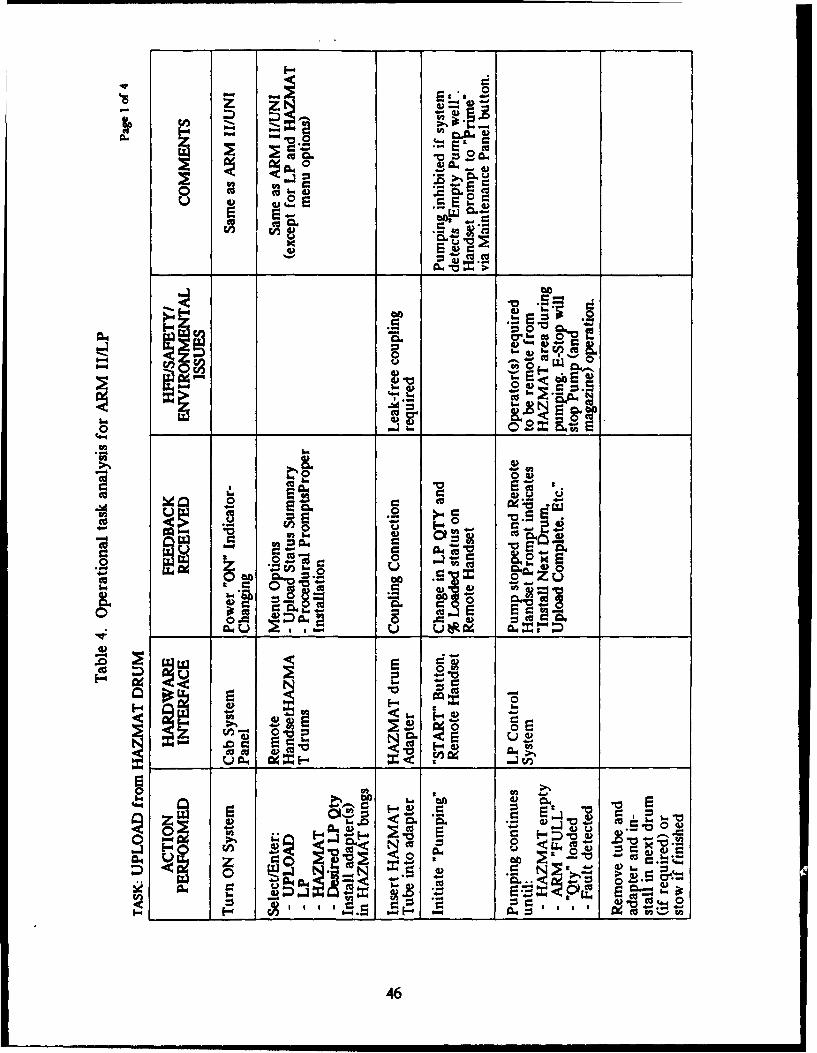
IIOU
- 0
ri A
a)~t 4) 2 W~~*
@0,~L)8
4X Ev
00
0V
cn 0.o"g,4) 00
L0(A A4 = 2
tn" 0- E
o toz- a I @ 2.. ZL
4- 4 a5 ~0 dv" -0_ _ _ 40 E c i.. : -
-x-p
0. 00 4) -4V
464
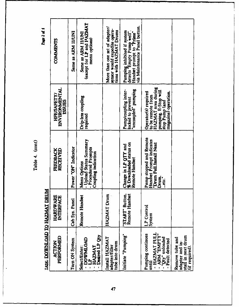
&Cc.
A~ C4
u0 o
iz .ý
v C:
80 0*0Z
47)
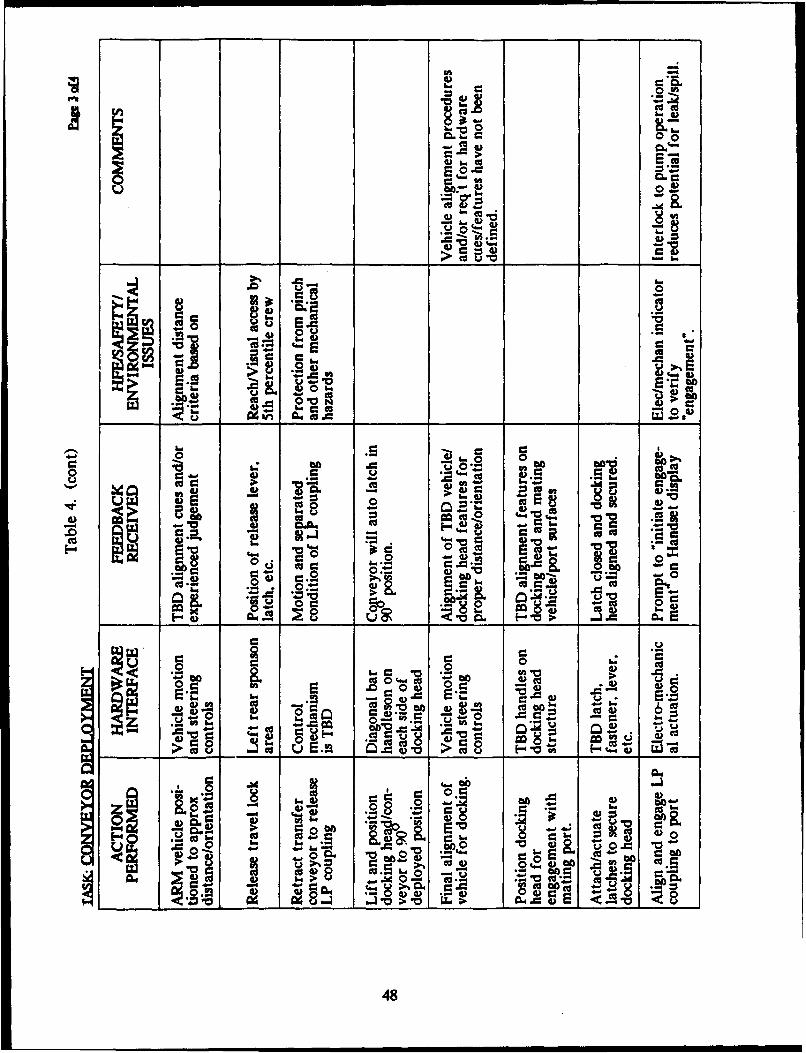
co 8100
0E IA
• - b:
wq CIOt
* 0.
so to 0 Vt
SEO.=
0 •
2- 0 . .- m.
E'. 1"u m r : - :s
w. m= ca= & .I1.v __.-_ _ _ _ _ _
00 C1 -0 00 1
r E%4) 0 : ==
b.. a. 4-. e
> .!2 W- > ct 0,M Jt
o-.. = -
"= ~4 C64 4. = an'"E • = "4-48
4-.-. .- .,' cIiV oODS
48
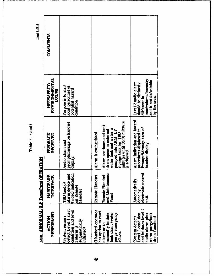
4-,
V )."
- o .-
~~ u
6)k
cc cc CLI 00
I- 0
4.) 6:0'W
4--9

Cz c0 .- *I =
- ~0~'
> Fj"0- ,_6', .€
Cc~q.-= o ý w' "s co.=! : •
cc.- tt z
4) V 4 ) & PE,
6)0-. CO .L) ~ -.- h ~ C 8co
to•4 . 00 , 0 z
W)
- el• . > , W1
0~ cc
o E-' co-o."N " r ',
,a.. 0 ,o . . .>. V W
___ o W0. r_
4.,-
w 9-.2 "_-=.2z C
00l. 1..00 0o _PQ > M-.7
Ix &. W F• . 8 t- .=.Q-. o
cu ~ ~ E > 0 C
>_'.u ,. 0.., .
bCD4. r %
4 vi ,-o -M r= two.
.I.-C '%-~ "-". 00-.ec
~c .0 00~ b.
u JD q ou W)> >Cu.V> 5~ 's ~
0= ,,-,- 6 )
-- : 6.) o
Cu0- -- 04;
500
Iw. " Z 00E.-
CuC t.6 6 >
a..U1
br) -c E 0
uCu
500
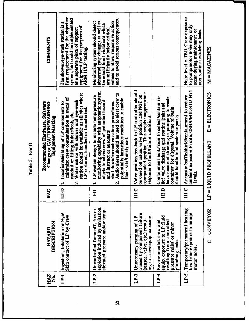
EOz' 00~
one =.l
_____ ~ ~~9 __ __ _ - 02 -S 0 >_______ ___
..-. A .- = cc
"= ~ ~ ~ ~ S. S. " =I..= .J' _0-E=
IL 40" .~ -
F . it
• el=, l Z.
.~ 0.w-.-• . •.
- 0.
=.0 it . .-. o9 :*. &
2.,,,___ ,,,,_= , === _,•._• -F' .•_8=== - ow
04 -.0 9 , u
0.- Q.
•-€ .c.- -, - c
0'1 0 L Er-
00
S"• -- ' P0 I u --
S-0 be
"O= -all_.
___ __ __ Cc~ S__ _ _ _~ 2.__ C. Col 8.= _ =_= ,...v = ,-o=
in n Z
5:1
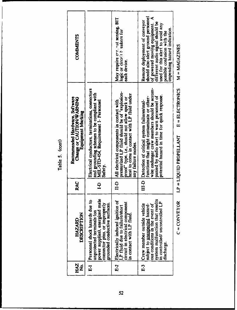
0 C 0"
00
fm =
0
0. = in >, Q
-. cr 0..- ;6
~j.4Uto- c• .0 •_ -
o t• N,
an
'~9) Cc)
0...
o .l cc
M E-5
00
Do0I ft-8Y b
-0 cc u
V &
= t --0 75
0 04-g R C:
0 0 c52
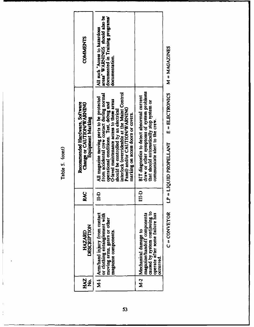
120
r. 0
EE•-• II
' 8 0.. = cc..-
~53
~ ~ Icc Ac~
o * ~ ~ CO ccV6 180 SO 80
* ~ 8.~: 0
.to
A~ 0
be 0
53U

54
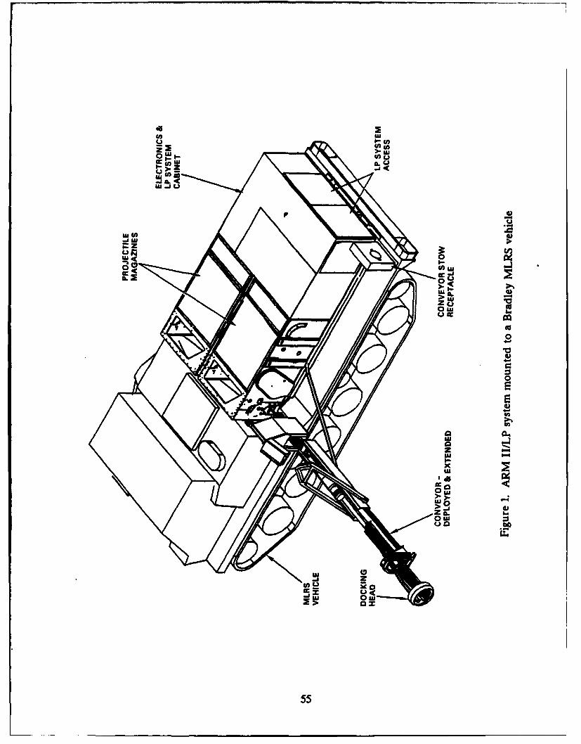
de U)
I.- (A
-i IL
LVI
zz
w 0
0 4)AUX --
00O
> U
55Z
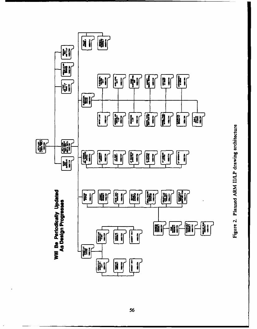
U S
i'~i
" I
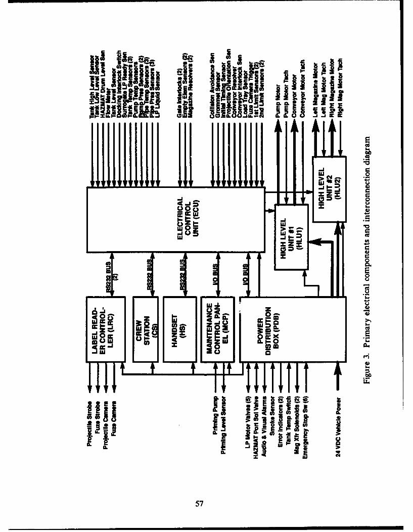
S818 188 MC
60
4).9
0 0rc cc
UZ i LE
0
00
Ic1.4
0A
ulu
.1.
11657
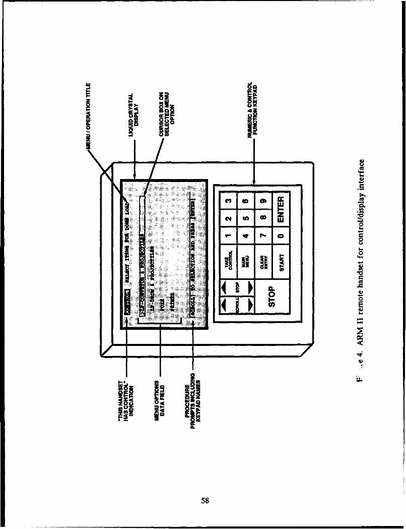
00
Im
- cc
0U
E4~
ru fn99 MOM
58 ,a
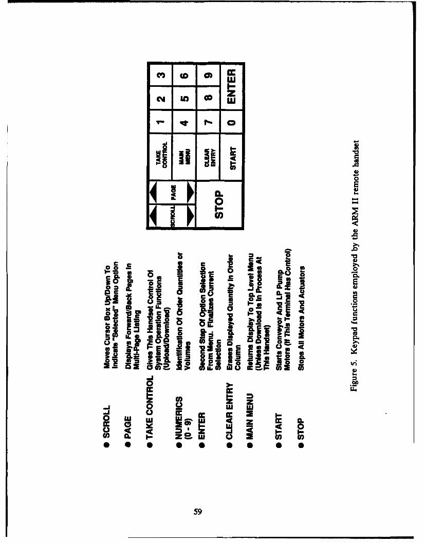
Ce) CD 0) E'
l-
-- q I - 0
_Jj
00
COOc a 00 S 1
Cc _S E, 2_ 0
' Q6.S ' 0
-1 0 j IaI & aI<C
!IJ iII _ - ! SI
II E- o = % _-I al i+ +.i I"
0 b
o +, I,, i.s, -. I0U L w z2.. 4c Z I Cl •
CC 0u Q 4c 0
59
06
00
..... .. . . .
600
I I
I1LL
61u
0
14)
cc
0
., . .6
62)
I&ce
00
fl -a
Ico
63
i dl 0
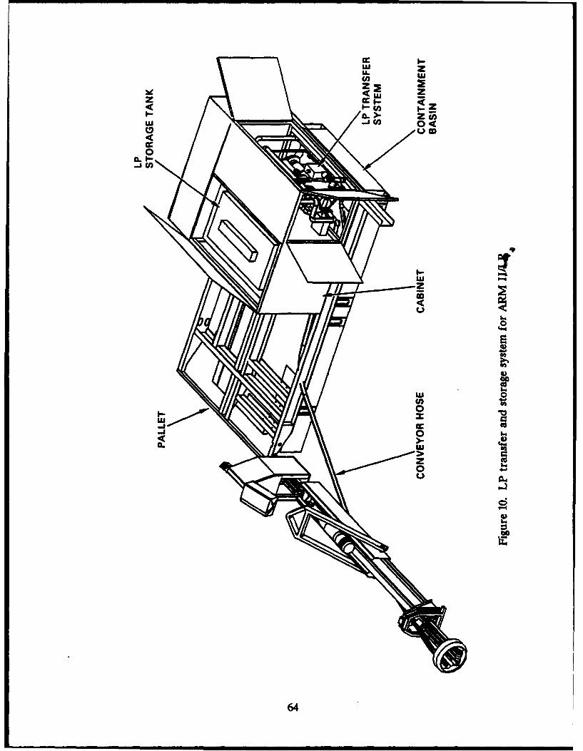
urn
0#4.4
4)
4)
0
'.44)
'.4
*12
4)I.4
64
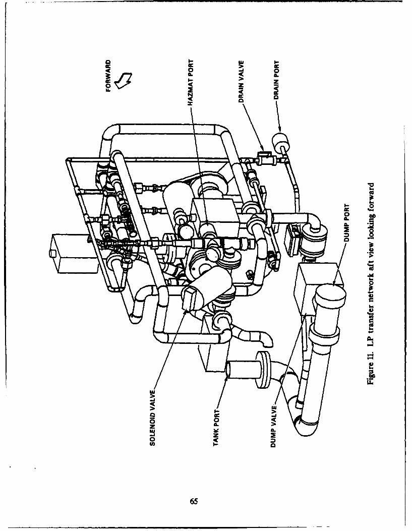
0 E
o___ o0
LLa
>A2
U-;
04
• - -
LUL
56 0
00IA)
65)
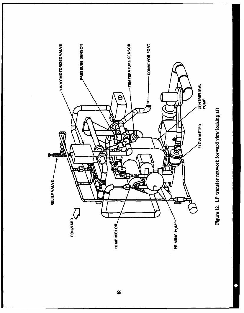
0 0 c
(A in 0z z IL
aw w0
w >
co 0w uw
CLa
)I-
'U
0
14..
0*1
us.>4
> 4.o
LLi
LS..L4-
0
0 0
SL S
66
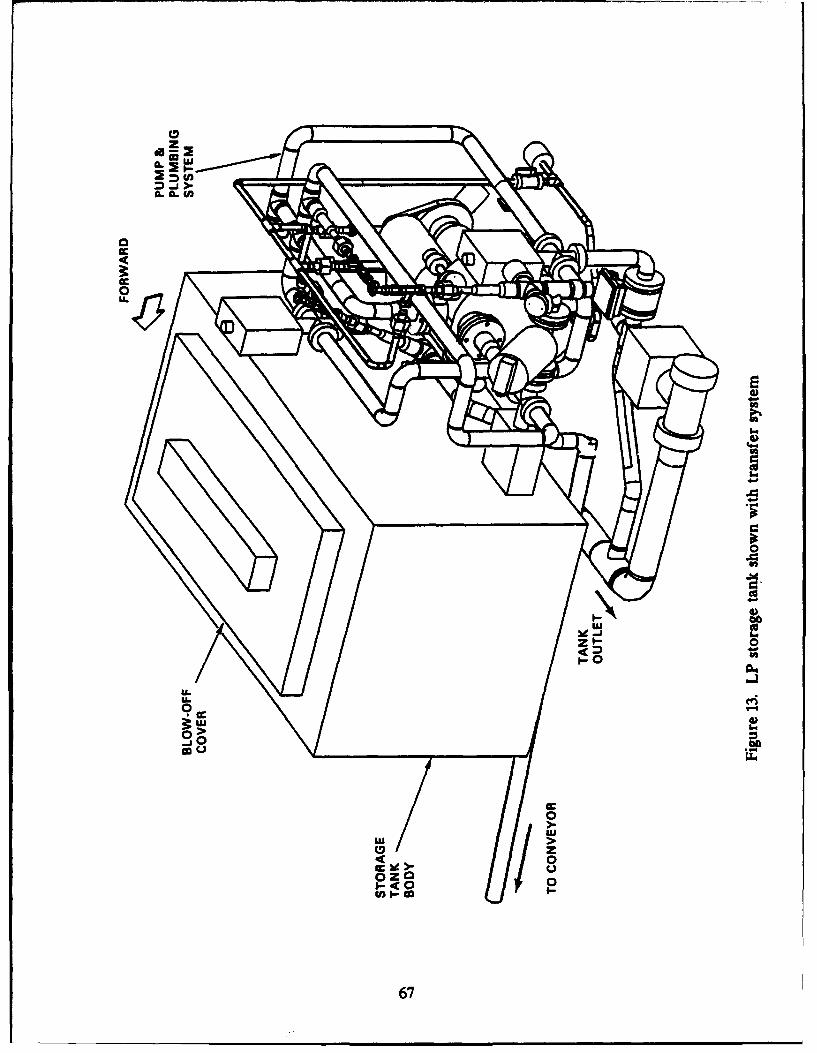
0
.5a..
C zU
>V
CL CL U
CcU
Cc-
LUU
Z 0)-o-
U.)
00
0 00go)
CCc
I-c
67
E CL
V ~
<In
u- 0
S l
CL IM.c
2E sm ccIC% 0.=
CL~rio
~i t rLP
0a 05-3v
U. 3: w~>%b 00
:668
I-
LUU
LUU
0.0
44
LU
uhi
I--
0
LUU
69
ull
.ini
0)mru
07
4)M
-4-1
.04c w
Iv 04
700

THIS PAGE INTENTIONALLY LEFT BLANK
71

THIS PAGE INTENTIONALLY LEFT BLANK
72
!m
-03
ooil
35 0
a .5
S_..
73
U.
0 V0
CL U. C.
CL 0I0 r-
a a- 0
- I "cc
1oE.
8 ~ I
740
I•c 0
-- X'
CSu
!- 7
:EI0
IIi IUb. I n
i +CuU
"14-
01Oz
LU 8.4
heJ
z LU
Uo 001
U) a
LULul)4
0 (nI~ 0>
LU ~ 4
Iu m
76
'Lii
xi
4)
ono
... ,,. . . .. .... ....
0 4044-
In0
•~ ~~ e I]!i i i
Al
. i i i . . ... .% n on on on % %
in ' CI,-
777777
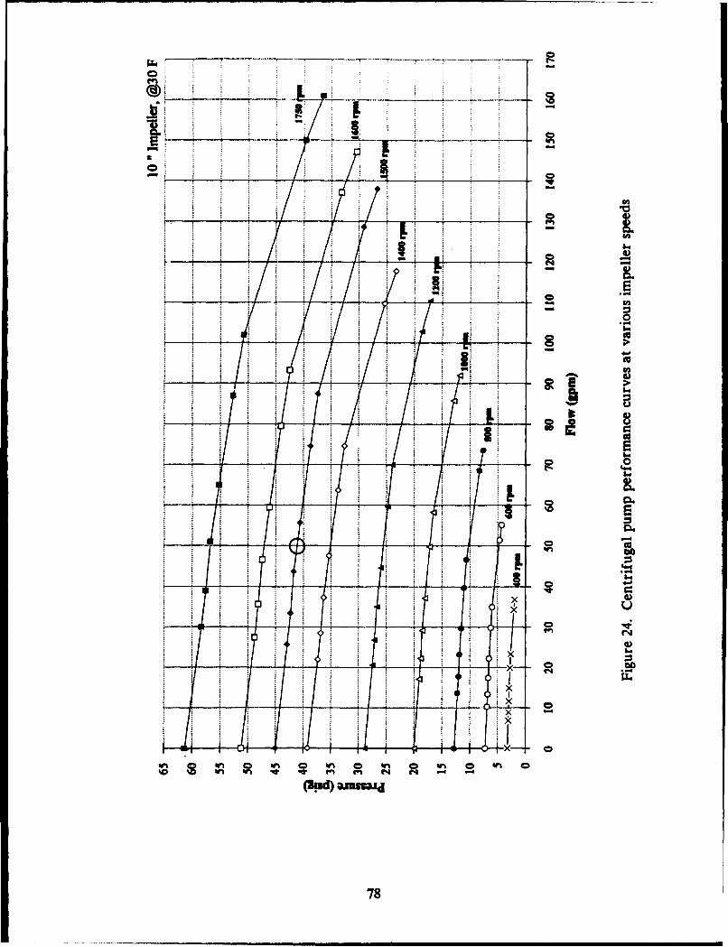
0 4
WW -W en (
Mid) wm0
78-
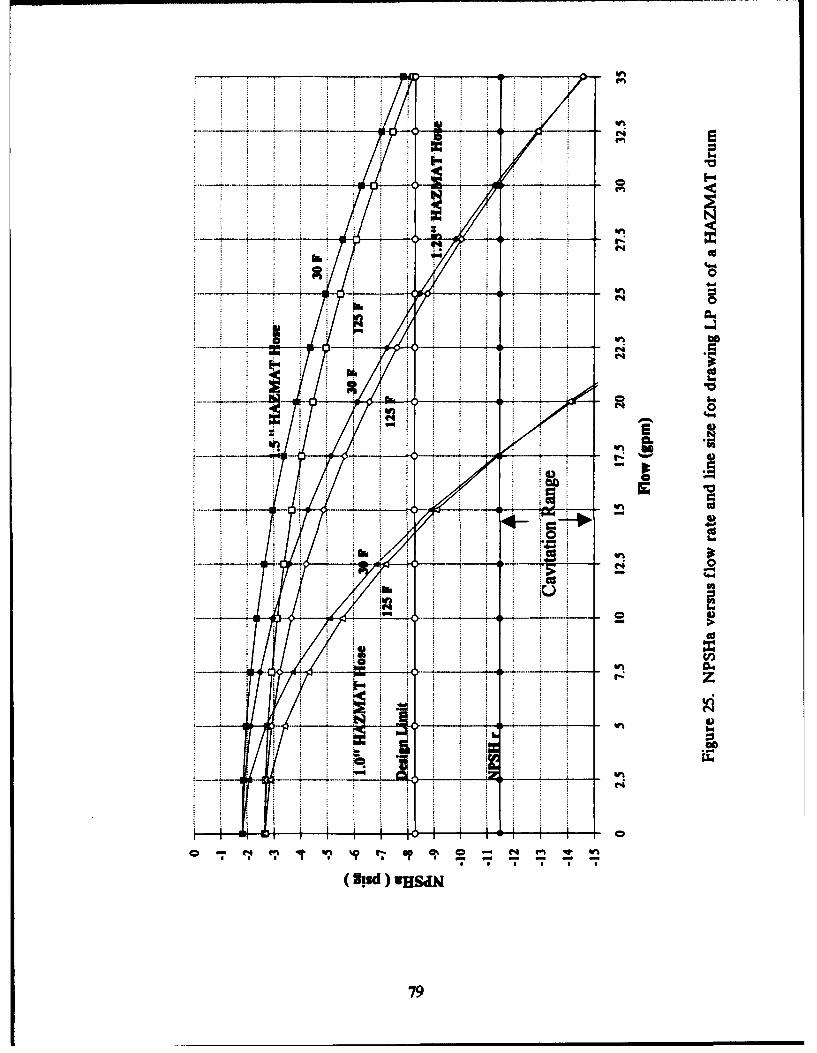
Kr-ro
400
is-
100
S.1 hi~j
-- 79
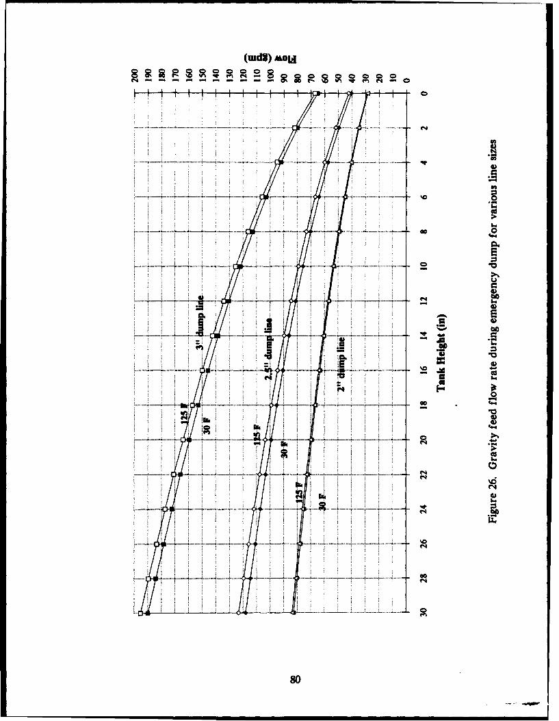
(udg) &OLoi
0000
;;4)
-. 000-
t4)
C4)
a.0
.. . ...... .. .. .. ..
80C
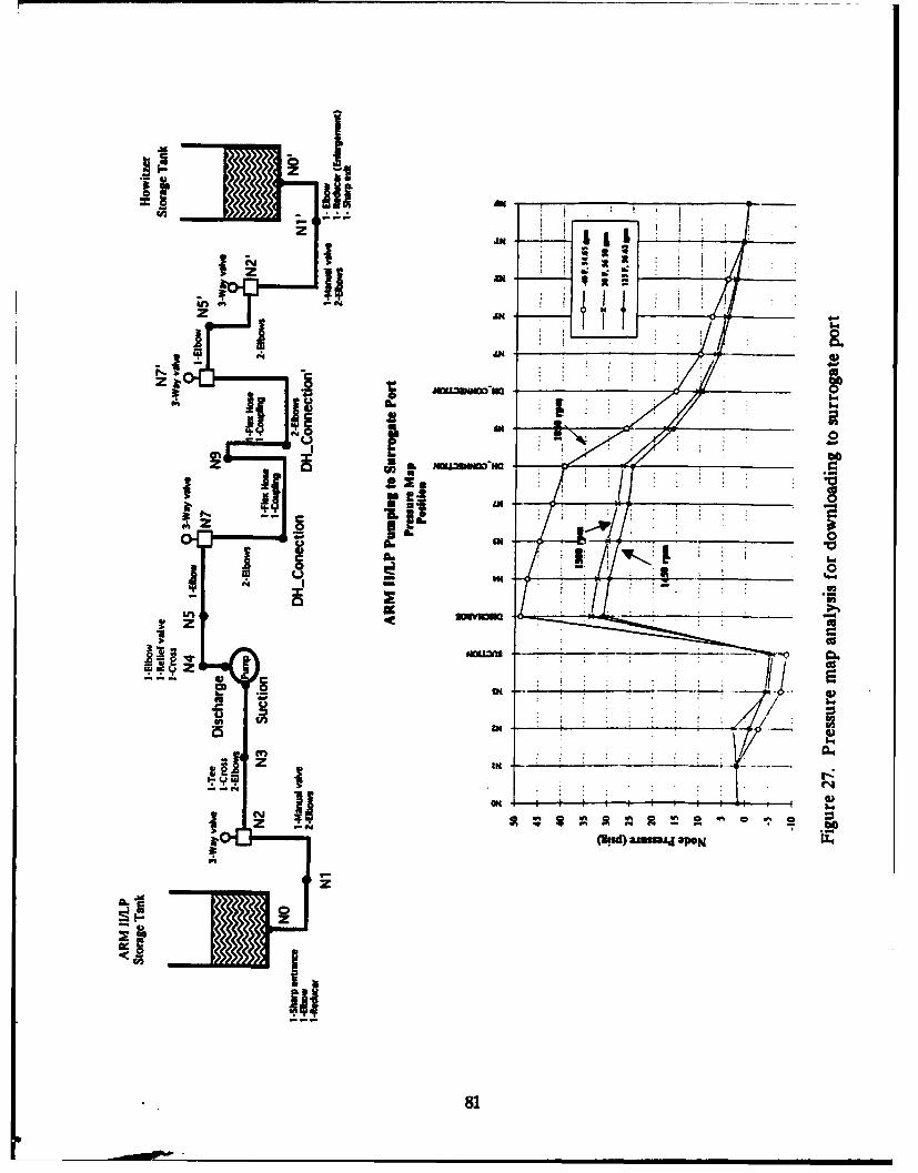
Lwiii IN*6
Z I
N.I b�.SN ___
I 'N.b.Da
Jmu�,m�mmSA.aF .4 2
Z 1 .22. /-- tEl11"
8. SN
a.ii #4
� z*1 _______________ *1
�Y Z
& S _____
S..u� �fl
I ______________
N
z(3sd)aJusuaJj.po�j -
z
4'
Ii�J
81
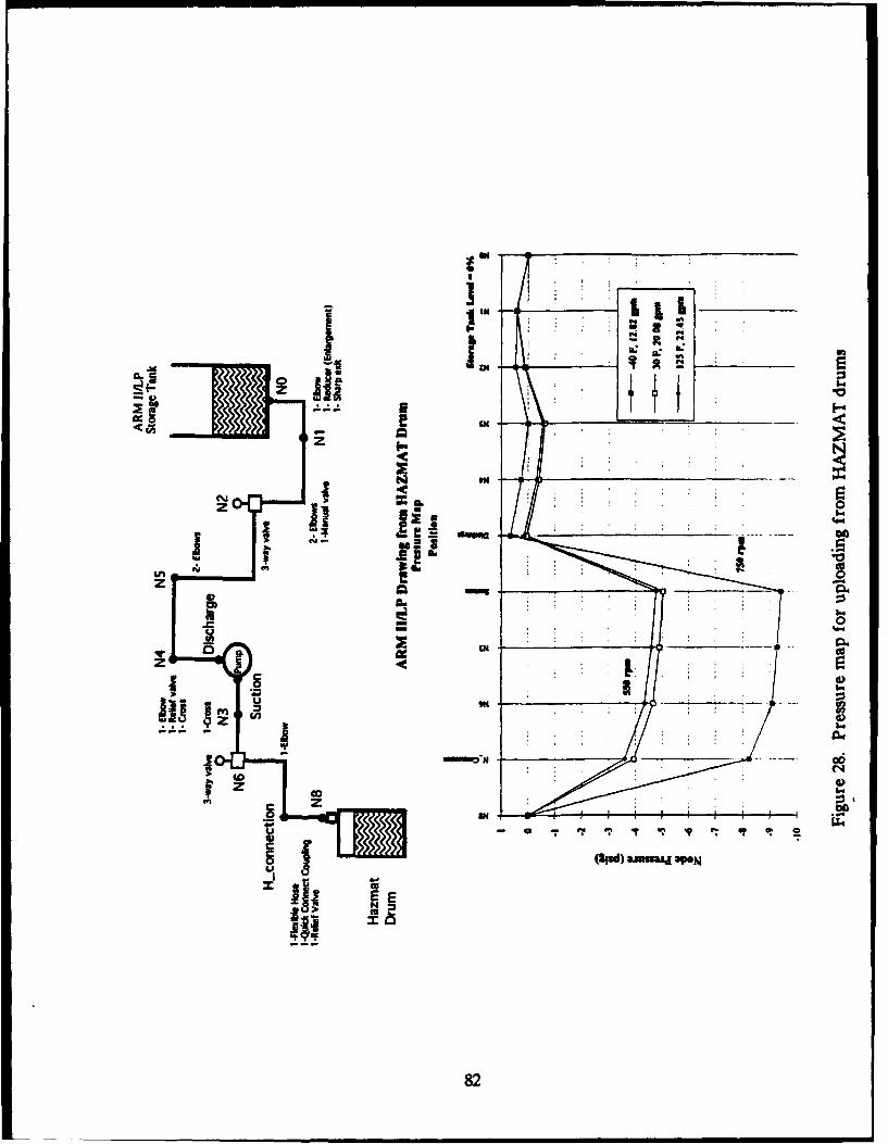
IW
L 104-j a 0 of
N ON
~0 06
on zf
aa
4 OF
82
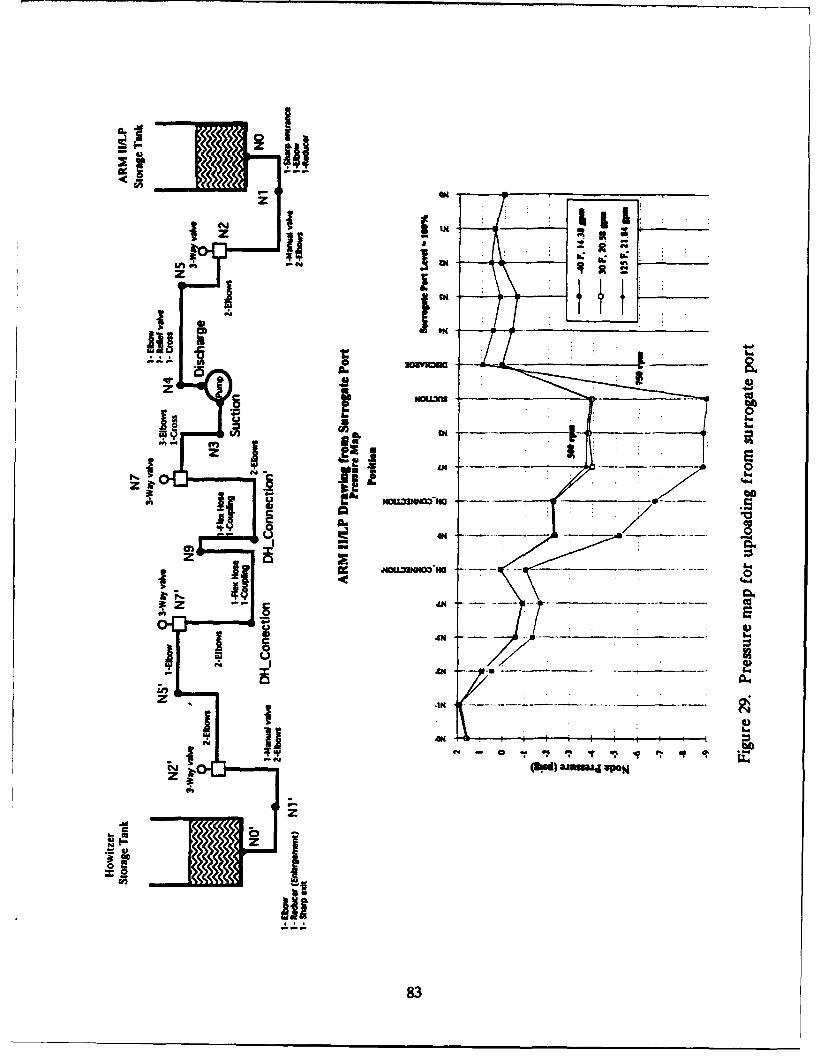
0 -IN
In~ C9 ~ s Nz
C", . I
z -IF z
II I
=AN
83
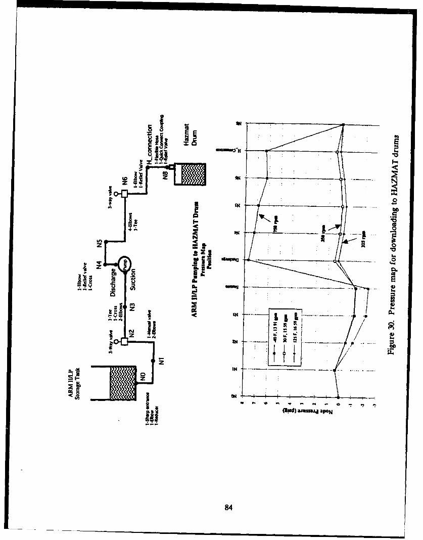
000
IINN
LiM~z*
V d~wpz 16iCHf.
TU 1
zhd.us~a.
lot4
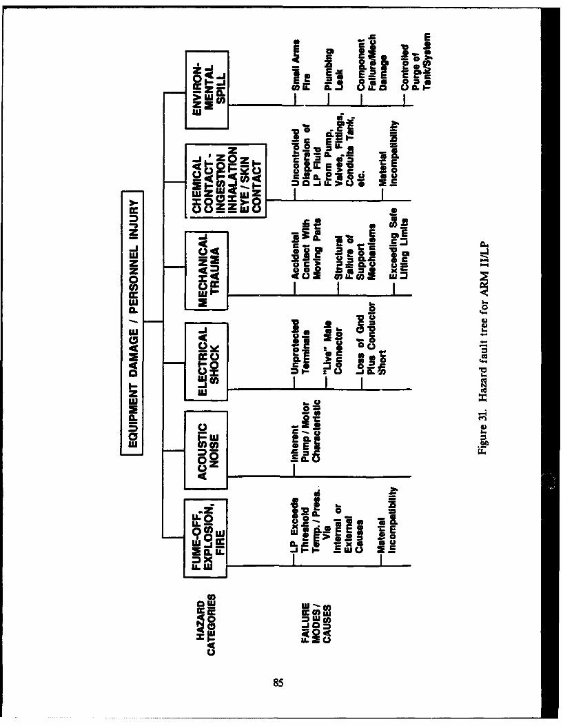
IJ I
-, UE E
00 &A.1 660
0.- 0 .
-0 CbC.L
CZm~I L c
0. 1..
to0.2 2 0
Ow
02
C) 185
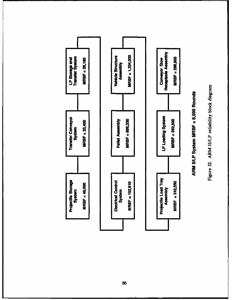
S"i piij
iia. smLLor a 01
0 cccc
v co
z .V
Li , . '
Ll.
fI IV E6
LL 5 .0.~- a UII cc
REFERENCES
1 Gagnon, Joseph N., et al., "155-mm Artillery Rearm Module II, Phase 1. ContractorReport ARFSD-CR-92002, ARDEC, Picatinny Arsenal. NJ, March 1992.
2 Liquid Propellant 1846 Handbook, Report No. JPL D-8978 NASA Jet PropulsionLaboratory, Pasadena, CA, March 1992.
87

88
DISTRIBUTION LIST
CommanderArmament Research. Development and Engineering CenterU.S. Army Tank-Automotive and Armaments CommandATTN: SMCAR-IMI-I (3)
SMACR-GCLSFAE-FAS-AF (10)SMCAR-AEE-BR (S. Einstein)SMCAR-AES-M (P. Bonnett)SMCAR-FSA (10)SMCAR-FSA-F (L. Pavagadhi)SMCAR-FSS-DF (W. Denery)
Picatinny Arsenal, NJ 07806-5000
AdministratorDefense Technical Information CenterATTN: Accessions Division (12)Cameron Station, VA 22304-6145
DirectorU.S. Army Material Systems Analysis ActivityATTN: AMXSY-MP
AMXSY-CM (D. Fordyce)Aberdeen Proving Ground, MD 21005-5066
CommanderChemical/Biological Defense AgencyU.S. Army Armament, Munitions and Chemical CommandATTN: AMSCB-CII (Library)Aberdeen Proving Ground, MD 21010-5423
CommanderU.S. Army Edgewood Research, Development and Engineering CenterATTN: SCBRD-RTB (Aerodynamics Development Team)
SCBDR-CE (N. Yura)Aberdeen Proving Ground, MD 21010-5423
DirectorU.S. Army Research LaboratoryATTN: AMSRL-OP-CI-B (Technical Library)
AMSRL-SLAD (A. Young)AMSRL-HR-SC (J. Waugh)
Aberdeen Proving Ground, MD 21005-5066
DirectorBenet Weapons Laboratory, CCACArmament Research, Development and Engineering CenterU.S. Army Tank-Automotive and Armaments CommandATTN: SMCAR-CCB-TL
SMCAR-CCB-D (R. Fiscella)Watervliet, NY 12189-5000
89
DISTRIBUTION LIST (CONTINUED)
DirectorU.S. Army TRADOC Analysis Command-WSMRATTN: ATRC-WSS-RWhite Sands Missile Range, NM 88002
CommanderTank Research, Development and Engineering CenterU.S. Army Tank-Automotive and Armament CommandATTN: AMSTA-ZED (M. Dolecki)
AMSTA-DIT (Library)Warren, MI 48397-5000
CommanderU.S. Army Test and Experimentation CommandATTN: CSTE-TFS-W (G. Wells)Ft. Sill, OK 70573-6100
CommandantU.S. Army Field Artillery SchoolATTN: ATSF-CN (S. Pierson)F. Sill, OK 73503-5600
CommandantU.S. Army Ordnance Missile and Munitions Center and SchoolATTN: ATSK-CMT-Z (C. Doub)Redstone Arsenal, AL 35897-6500
CommanderU.S. Army TRADOC Analysis Command-SACATTN: ATRC-SAC (P. Smock)Ft. Leavenworth, KS 66027-5200
CommanderU.S. Army TRADOC Analysis Command-LEEATTN: ATCL-L (T. McGrady)Ft. Lee, VA 23807-6140
90