170114 wtc2017 challenges and solutions for large scale ... · beneath built-up area – fsv...
TRANSCRIPT

Proceedings of the World Tunnel Congress 2017 – Surface challenges – Underground solutions. Bergen, Norway.
1
1 INTRODUCTION
NATM tunneling in soft ground and in urban environment is a common construction method in central Europe. In Austria exists considerable experience which is reflected in a guideline for design and construction of tunnels in soil beneath built-up area – FSV (2013). Prerequisite for successful design and construction is the good knowledge and understanding of the ground and boundary conditions.
The tunnel support consists commonly of an outer reinforced shotcrete lining (primary lining) and a water tight reinforced concrete inner lining (secondary lining). The tunnels are designed as a tanked system without permanent groundwater drainage. Between primary and secondary lining is foreseen a plastic membrane to reduce secondary stresses due to constraint.
The alignment of the tunnel is often predetermined by local boundary conditions.
Therefore, particular challenges for tunneling may arise which have to be solved.
2 VIENNA, LAINZER TUNNEL LOT 44
2.1 Description of the project The Lainzer Tunnel project connects the western and southern railway trunk-lines in the city of Vienna. The mined tunnel sections with a total length of about 10.140 m tunnel tubes comprise several construction lots. The safety concept requires a total of 24 vertical emergency escape shafts which are connected to the running tunnels by horizontal galleries.
The lot LT44 provides the connection to the Donauländebahn. Construction of Lot 44 was completed by end of 2008. More detailed description of the design and construction is presented in Daller et al. (2011).
The typical geological profile is shown in Figure 1 consisting of fill, gravel and silt which is interbedded with sand layers.
Challenges and Solutions for large scale Tunnelling in Urban Environment.
G. Atzl iC consulenten ZT GmbH, Vienna, Austria.
ABSTRACT: Tunnelling in soft ground in urban environment is a challenging task which requires comprehensive design solutions tailored to the particular ground and boundary conditions. This paper illustrates some interesting design solutions for tunnels with large cross-section below existing railway line and freeway tunnels below major freeway - both in Vienna in stiff clay and dense sands. Special measures as de-watering from surface, jet-grouting and pipe roofs were applied. Other challenging tunnel drives were designed for subway tunnels for the project Metro 4 in Budapest in stiff clay and dense sands. The most difficult tunnels are located below the Danube in fault zones and others below existing buildings. Special measures as freezing and de-watering were designed. In Stockholm the mixed face conditions between hard rock and loose sand was a challenging task for tunnel design and construction. For safe tunnelling jet-grouting canopy turned out to be suitable.
All cases confirmed the experience that for tunnelling in urban environment the knowledge of the ground is most important. Any cost for site investigations can save major cost during later construction.
.

Proceedings of the World Tunnel Congress 2017 – Surface challenges – Underground solutions. Bergen, Norway.
2
Figure 1. Typical geological profile, (Daller et al. (2011))
Free groundwater is present in the sand and gravel layers with two main groundwater aquifers, separated by a layer of silt/clay of thickness within the meter range.
Beginning from the starting shaft at the eastern end a 128 m long double-track tunnel was constructed. From there the double track tunnel was enlarged in 3 sections to accommodate the transition to two parallel single-track tunnels. At the beginning of the single-track tunnels the soil between the tunnels had to be replaced by a reinforced concrete pillar. The length of the concrete pillar section is 89 m, the adjacent single track-tunnels 559 m and 614 m respectively. The tunnels are located in tertiary soil and the overburden above tunnel crown ranges from 8 to 15 m.
Since the tunnels of Lot44 are driven below the groundwater table, vertical wells (gravity and vacuum) were necessary to lower the ground water in sand and gravel layers and to reduce the remaining pore pressure to acceptable values during construction. In addition drainage pipes have to be drilled from tunnel heading during excavation.
2.2 NATM-excavation with large cross-section Particular challenge of the project was the large excavation cross-section of the double track tunnel with a total cross section area of 128 m2 to 185 m2 (see Figure 2). The boundary conditions for the foreseen NATM-excavation were low overburden of some 10 m underneath existing railway tracks under operation (Donauländebahn).
Figure 2. Double track tunnel widening section 185 m2.
Due to the soft ground conditions the excavation cross-section is subdivided into two side-wall galleries, followed by top heading excavation, bench and invert excavation between the galleries. Excavators are used for excavation. The main support elements comprise a 35 to 40 cm thick shotcrete lining reinforced by 2 layers of wire mesh, lattice girders, and forepoling pipes or steel lagging.
The design of the tunnel outer lining is based on numerical partial coupled analyses using elastic-plastic Mohr-Coulomb model considering pore pressure development.
Figure 3. Excavation double track tunnel with side drifts.
An extensive monitoring program and geotechnical risk management was utilized. The monitoring included 3-D monitoring deformation of the shotcrete lining, surface points, inclinometer and piezometer. Based on the measured lining deformations the utilized capacity of the shotrete lining was evaluated.
Proceedings of the World Tunnel Congress 2017 – Surface challenges – Underground solutions. Bergen, Norway.
3
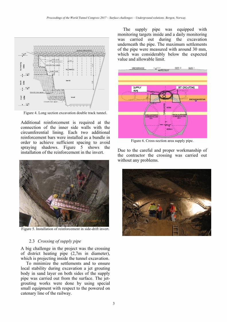
Figure 4. Long section excavation double track tunnel.
Additional reinforcement is required at the connection of the inner side walls with the circumferential lining. Each two additional reinforcement bars were installed as a bundle in order to achieve sufficient spacing to avoid spraying shadows. Figure 5 shows the installation of the reinforcement in the invert.
Figure 5. Installation of reinforcement in side-drift invert.
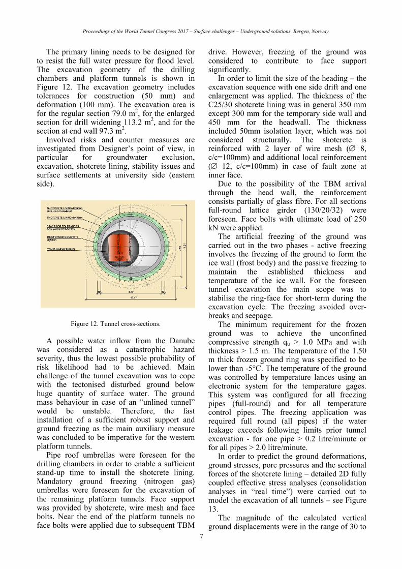
2.3 Crossing of supply pipe A big challenge in the project was the crossing of district heating pipe (2,7m in diameter), which is projecting inside the tunnel excavation.
To minimize the settlements and to ensure local stability during excavation a jet grouting body in sand layer on both sides of the supply pipe was carried out from the surface. The jet-grouting works were done by using special small equipment with respect to the powered on catenary line of the railway.
The supply pipe was equipped with monitoring targets inside and a daily monitoring was carried out during the excavation underneath the pipe. The maximum settlements of the pipe were measured with around 30 mm, which was considerably below the expected value and allowable limit.
Figure 6. Cross-section area supply pipe.
Due to the careful and proper workmanship of the contractor the crossing was carried out without any problems.

Proceedings of the World Tunnel Congress 2017 – Surface challenges – Underground solutions. Bergen, Norway.
4
Figure 7. Excavation underneath supply pipe.
2.4 380 kV-high voltage cable The existing 380 kV-high voltage cable is located within the settlement trough of the double track tunnel including the widening section and section with the pillar gallery. The two 380 kV cables are placed in cable ducts in a depth of 2 m from the surface. These cables were the only electric supply for the 23rd district of Vienna until middle of 2006. Therefore the original design included some special protection measures.
A jet-grouting layer between the cables and the tunnel was carried out to reduce the settlements of the highly sensitive cables to acceptable values. Further special measures were not executed based on a risk assessment considering additional electric supply options after middle of 2006 for the 23rd disdrict.
The applied measures together with the heading concept with two sidewall galleries and subdivided faces proved to be successful and the final settlement of the cables resulted in the range of 30 mm.
3 VIENNA, SUBWAY LOT U1-9
3.1 Description of the project The construction lot U1/9 with “Altes Landgut” station is part of the extension of underground line U1 to the South from Reumannplatz station to Oberlaa station. The U1 is extended by 4.6 kilometres and five stations. By end of 2017, it will be the longest underground line in Vienna (19.2 km). The Construction lot U1/9 consists of two app. 25 m and 30 m deep cut & cover shafts, two mined app. 120 m long platform tunnels, four mined single track running tunnels, several cross-passages and one emergency shaft. The tunnels are located below residential buildings, main roads and the very critical “Laaerberg Tunnel” of the A23 freeway – see Figure 8.
The underpass of the A23-tunnel was the biggest challenge of this project beside the excavation of the station tunnels. Main focus of the design of the NATM tunnels was the minimisation of settlements and achieving high safety level. Prior tunnelling the structural capacity of the buildings at surface and of the Laaerberg Tunnel is improved partly.
The tunnels are located mainly in the very stiff Miocene silt/clay layers which have a relatively homogeneous structure. Those layers basically comprise of slightly sandy, grey, dark grey to grey-blue silts/clays, turning semi-solid to solid with increasing depth. A thick mixed layer of fine sand or sandy silt layers, 5 m thick on average, runs through the construction lot from approx. 20 m below ground level. It was necessary to pre-drain this layer by filter wells from surface.
Extensive monitoring was foreseen to control the performance of the excavation works. The monitoring devices comprise bolt gauges for 3-D trigonometric shotcrete shell displacement measurements, surface settlement points, liquid levelling system on A23 tunnel, horizontal automatic horizontal inclinometers above the tunnel tubes underneath the A23 and in above the platform tunnel in places. The observed deformations during construction were within the predicted range.
Further details regarding the tunnel design approach and experience during construction is presented in Atzl et al. (2015).
3.2 Underpass of A23 Laaerberg Tunnel The freeway A23 is the most frequented road in Austria with 170000 vehicles per day. Any interruption of the traffic caused by the underpassing tunneling would result in major traffic jam and related cost. Therefore it was of utmost importance to avoid any damages to the A23 Laaerberg Tunnel, which would jeopardize its serviceability and structural capacity. The freeway bureau decided to refurbish during the years 2011 and 2012 the Laaerberg Tunnel (which was built in 1972). These refurbishing was unfortunately prior of the tunnel exaction for the subway, which had to be carried out in 2014 just below the Laaerberg Tunnel.

Proceedings of the World Tunnel Congress 2017 – Surface challenges – Underground solutions. Bergen, Norway.
5
Figure 8. Geotechnical cross-section at the A23 Laaerberg tunnel.
The structure of the Laaerberg Tunnel consists of 3 reinforced walls parallel to the freeway and of the ceiling girders with thin reinforced concrete slab on top. No base slab exists. In order to minimise the risk for damaging the newly refurbished Laaerberg Tunnel, the subway designer was allowed to design some special preparatory works, which were carried out during the refurbishing. These preparatory works included jet-grouting at the central diaphragm wall of the Laaerberg tunnel. This D-wall reached below the invert of the subway tunnel, consisting of panels c. 6 m long and gaps c. 2m in between. Scope of the jet-grouting was to close the gaps with stronger material in order to achieve an arching effect during tunnel excavation. The new concrete pavement of the freeway has been reinforced at the crossing area in order to get some bridging effect in case of local cavities caused by the tunnel excavation. Extensive analyses have been carried out on the Laaerberg Tunnel structure in order to evaluate its allowable differential settlements.
The running tunnels underpass the existing A23 Laaerberg tunnel over a length of c. 35 m – see Figure 9. A thicker reinforced secondary lining is provided in this area and also extends for several adjacent metres at both ends. Tunnelling is carried out underneath pipe roof umbrellas. The area of the sawtooth-like excavation amount to c. 42 m2 min. / 54 m2 max. in the case of a 45 cm thick cast-in-situ secondary lining and a 40 cm thick shotcrete primary lining. The primary lining underneath the A23 is fully electrically insulated from the remaining structure via GRP reinforcement and FPO sheeting.
Figure 9. Layout underpass A23-tunnel
The pipe roof umbrella comprises 12m long steel pipes (dia. 114mm, t = 6mm) with a spacing of normally 300mm at the bore face and a longitudinal overlap of at least 4m. The pipes and annular space are grouted with a cement suspension from the driving end of the pipe. The umprellas next to existing diaphragm walls were predrilled by core drillings and inserted dia. 176 mm steel pipes. Subsequently the dia. 114 mm steel pipes were drilled via the 176 mm pipes until reaching the designed 12 m length see- Figure 10.
Figure 10. Pipe roof installation.
The axes of the A23 tunnel and the subway tunnel are angled at ca. 60°, allowing the diaphragm walls to be separated into short sections during undercutting and to be underpinned with a reinforced shotcrete ring. A reinforced shotcrete primary lining with all-round lattice girders was constructed in the entire underpass area. The fine sand layers were drained from above ground using vacuum filter wells and vacuum lances were also deployed from the driving side where necessary. Systematic face anchoring and short ring closure were provided in order to minimise settlements. In particular the stiff primary lining (40 cm thickness) contributed significantly in low settlements.
Control values such as advance warning, warning and alarm values were defined for all

Proceedings of the World Tunnel Congress 2017 – Surface challenges – Underground solutions. Bergen, Norway.
6
monitoring parameters considered. The horizontal inclinometers and tunnel levels generate automatic messages when the control values are exceeded. During excavation shotcrete lining displacements were less than 10 mm, settlements of the A23 road surface was in the region of the predicted 15 mm and the settlements of the diaphragm walls were below 10 mm. The most critical specification was the twisting of the girders spanning the centre diaphragm wall with an advance warning ratio of 1:1000 and an alarm ratio of 1:500. Measured twisting did not exceed c. 1:2000, due to more favourable characteristics encountered.
4 BUDAPEST METROLINE 4, LOT C05A FÖVAM TER
4.1 Description of the project The Fövam ter station of the Budapest Metro 4 Line is located at the East bank of the river Danube. The station consists of the 34 m deep central diaphragm-wall box with mined tunnel extensions (NATM) for platform tunnels at both sides with length of some 25 m. The overburden at the platform tunnels is about 21 m at the lower embankment and reaches a minimum of about 10 m within the Danube. The water height is between 5 to 9 m above the Danube bed.
The tunnels are driven in layers of tertiary sands, sandstone and clay which are crosscut by major through-going faults and fault zones. The minimum cover of the Tertiary soils above tunnel crown is about 4 to 5 m in case of the regular section. The Tertiary soils are overlain by Quaternary gravel.
Fault zones are inter-connected with the gravel and may exhibit quite high permeability. Thus it is possible to get water inflow from the Danube via the high permeable gravel and fault system into the excavation. In turn unstable conditions could occur which may lead to a collapse. The tunnel excavation requires an advanced ground treatment in order to provide sufficient strength and low permeability to minimize the water inflow to the tunnel. Ground freezing umbrellas, grouted pipe roofs and grouting measures are foreseen as special measures.
During excavation a comprehensive monitoring program was performed as 3D-trigonometrical deformation measurements of
the shotcrete lining, horizontal inclinometer above the platform tunnels, temperature gauges in horizontal drillings (for freezing control) and piezometer.
Further details regarding the tunnel design approach and experience during construction is presented in Atzl (2011).
4.2 Platform tunnels below Danube The original structural layout of the station –
according to the tender documents - is shown in Figure 11 in blue colour. The station consists of the app. 34 m deep diaphragm-wall shaft and the obliquely aligned platform tunnels. Both platform tunnels were intended to be located below the river Danube for a length of some 45 m. The overburden at the platform tunnels were about 21 m at the lower embankment and would reach a minimum of about 10 m within the Danube, with about 5 to 9 m of the additional water height.
Figure 11. Plan view Fövam Ter station.
Based on findings of further ground investigation campaigns, design process and risk assessment - in September 2008 a change of the layout – red line in Figure 11 - was released where the alignment is lowered by 0.40 m. The platform tunnels below the Danube are shortened by some 50% in length as well as some 25 m long additional Platform tunnels at the eastern side of the station below the University building. This solution had 2 short drilling chambers for the installation of ground freezing umbrellas for the remaining tunnel below the Danube. Nitrogen freezing method was applied. The freezing works were commenced in December 2008. The NATM tunnels were successfully constructed and completed by end of March 2009.
Proceedings of the World Tunnel Congress 2017 – Surface challenges – Underground solutions. Bergen, Norway.
7
The primary lining needs to be designed for to resist the full water pressure for flood level. The excavation geometry of the drilling chambers and platform tunnels is shown in Figure 12. The excavation geometry includes tolerances for construction (50 mm) and deformation (100 mm). The excavation area is for the regular section 79.0 m2, for the enlarged section for drill widening 113.2 m2, and for the section at end wall 97.3 m2.
Involved risks and counter measures are investigated from Designer’s point of view, in particular for groundwater exclusion, excavation, shotcrete lining, stability issues and surface settlements at university side (eastern side).
Figure 12. Tunnel cross-sections.
A possible water inflow from the Danube was considered as a catastrophic hazard severity, thus the lowest possible probability of risk likelihood had to be achieved. Main challenge of the tunnel excavation was to cope with the tectonised disturbed ground below huge quantity of surface water. The ground mass behaviour in case of an “unlined tunnel” would be unstable. Therefore, the fast installation of a sufficient robust support and ground freezing as the main auxiliary measure was concluded to be imperative for the western platform tunnels.
Pipe roof umbrellas were foreseen for the drilling chambers in order to enable a sufficient stand-up time to install the shotcrete lining. Mandatory ground freezing (nitrogen gas) umbrellas were foreseen for the excavation of the remaining platform tunnels. Face support was provided by shotcrete, wire mesh and face bolts. Near the end of the platform tunnels no face bolts were applied due to subsequent TBM
drive. However, freezing of the ground was considered to contribute to face support significantly.
In order to limit the size of the heading – the excavation sequence with one side drift and one enlargement was applied. The thickness of the C25/30 shotcrete lining was in general 350 mm except 300 mm for the temporary side wall and 450 mm for the headwall. The thickness included 50mm isolation layer, which was not considered structurally. The shotcrete is reinforced with 2 layer of wire mesh (Æ 8, c/c=100mm) and additional local reinforcement (Æ 12, c/c=100mm) in case of fault zone at inner face.
Due to the possibility of the TBM arrival through the head wall, the reinforcement consists partially of glass fibre. For all sections full-round lattice girder (130/20/32) were foreseen. Face bolts with ultimate load of 250 kN were applied.
The artificial freezing of the ground was carried out in the two phases - active freezing involves the freezing of the ground to form the ice wall (frost body) and the passive freezing to maintain the established thickness and temperature of the ice wall. For the foreseen tunnel excavation the main scope was to stabilise the ring-face for short-term during the excavation cycle. The freezing avoided over-breaks and seepage.
The minimum requirement for the frozen ground was to achieve the unconfined compressive strength qu > 1.0 MPa and with thickness > 1.5 m. The temperature of the 1.50 m thick frozen ground ring was specified to be lower than -5°C. The temperature of the ground was controlled by temperature lances using an electronic system for the temperature gages. This system was configured for all freezing pipes (full-round) and for all temperature control pipes. The freezing application was required full round (all pipes) if the water leakage exceeds following limits prior tunnel excavation - for one pipe > 0.2 litre/minute or for all pipes > 2.0 litre/minute.
In order to predict the ground deformations, ground stresses, pore pressures and the sectional forces of the shotcrete lining – detailed 2D fully coupled effective stress analyses (consolidation analyses in “real time”) were carried out to model the excavation of all tunnels – see Figure 13.
The magnitude of the calculated vertical ground displacements were in the range of 30 to

Proceedings of the World Tunnel Congress 2017 – Surface challenges – Underground solutions. Bergen, Norway.
8
50 mm, the horizontal displacements were in the range of 15 to 45 mm. Below invert – heave deformations up to 25 mm were predicted. The deformations of the ground were estimated up to 70 mm. Thus a deformation tolerance of 100 m was applied.
Figure 13. Structural analysis-section.
The calculated normal forces, bending moments and shear forces varied also versus time. The normal forces were in the range between 2000 and 2700 kN/m, the bending moments between 50 to 260 kNm/m. Higher bending moments were calculated at the “gotic corners” of the side drifts, but were not relevant due to increased shotcrete thickness due to the inner rounded shape.
The measured deformations of the shotcrete lining were in the range of 2 to 10 mm. The vertical and horizontal displacements were of similar magnitude. Some lining deformations in the range of some mm have likely occurred prior the first reading - but even so the observations are less than the predicted values.
The performed temperature monitoring confirmed the thickness and strength of the required frost body. The thawing process was observed until mid of June 2009, where most of the temperature gages showed plus temperatures up to 15 °C, only some gages at the western end of the freezing umbrella still showed slight frost temperatures of -1.5°C.
The measured pore pressures showed rather low values (less than 20 kPa) except the
piezometers PP-2 16 m up to 60 kPa and PP-2 24 m up to some 200 kPa. The latter one was located in the fault zone and the pore pressure was almost as large as the water level of the Danube. However, these pore pressures dropped significantly after 20th of February, when the North tube side drift approached the fault zone. The mentioned 200 kPa reduced gradually to some 40 kPa.
The measured surface settlements along the lower embankment were less than 15 mm.
The freezing caused in the horizontal inclinometer above the North tube in maximum 10 mm heave and settlements developed gradually with the tunnel excavation and reached the maximum value of 24 mm in June 2009 due to the thawing process. The maximum vertical ground displacement was 34 mm. These measured settlements are smaller than the predictions.
5 STOCKHOLM SÖDERMALMS TUNNEL
5.1 Project description
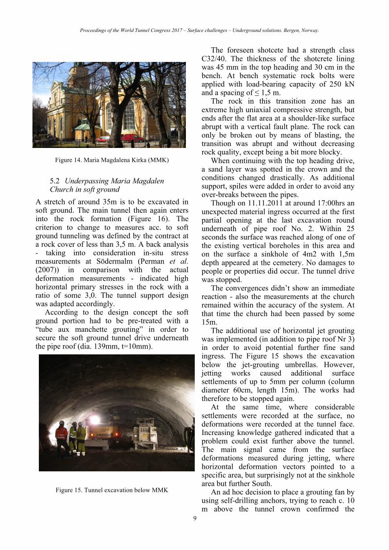
The Maria Magdalena Church is one of the oldest churches in Stockholm and is ranking under highest protected buildings. The Tunnel construction shall have minimal impact on the church and cemetery.
A double-track railway tunnel lining is foreseen under the Maria Magdalena church and the adjacent cemetery section app. km 35+620 – 35+673. The tunnel runs through hard rock and a buried soft ground valley. iC prepares the final design for the Contractor Züblin for this section based on the terms of a design and built Contract. In particular, grouting measures and a NATM drive under grouted pipe roof are designed in detail. High emphasise is paid for minimisation of surface and building settlements.
Main tunnel is of approximately 100 m2 and a service tunnel of 40 m2 in cross section. The length of the crucial design and build section is 53 m.
This project comprises the first major rail tunnel passing Stockholm in soft ground (“Esker”) with an NATM approach; special measures like pipe roof, grouting and jet-grouting are required. Further details are presented in Gamsjäger et al. (2012).
Proceedings of the World Tunnel Congress 2017 – Surface challenges – Underground solutions. Bergen, Norway.
9
Figure 14. Maria Magdalena Kirka (MMK)
5.2 Underpassing Maria Magdalen Church in soft ground
A stretch of around 35m is to be excavated in soft ground. The main tunnel then again enters into the rock formation (Figure 16). The criterion to change to measures acc. to soft ground tunneling was defined by the contract at a rock cover of less than 3,5 m. A back analysis - taking into consideration in-situ stress measurements at Södermalm (Perman et al. (2007)) in comparison with the actual deformation measurements - indicated high horizontal primary stresses in the rock with a ratio of some 3,0. The tunnel support design was adapted accordingly.
According to the design concept the soft ground portion had to be pre-treated with a “tube aux manchette grouting” in order to secure the soft ground tunnel drive underneath the pipe roof (dia. 139mm, t=10mm).
Figure 15. Tunnel excavation below MMK
The foreseen shotcete had a strength class C32/40. The thickness of the shotcrete lining was 45 mm in the top heading and 30 cm in the bench. At bench systematic rock bolts were applied with load-bearing capacity of 250 kN and a spacing of ≤ 1,5 m.
The rock in this transition zone has an extreme high uniaxial compressive strength, but ends after the flat area at a shoulder-like surface abrupt with a vertical fault plane. The rock can only be broken out by means of blasting, the transition was abrupt and without decreasing rock quality, except being a bit more blocky.
When continuing with the top heading drive, a sand layer was spotted in the crown and the conditions changed drastically. As additional support, spiles were added in order to avoid any over-breaks between the pipes.
Though on 11.11.2011 at around 17:00hrs an unexpected material ingress occurred at the first partial opening at the last excavation round underneath of pipe roof No. 2. Within 25 seconds the surface was reached along of one of the existing vertical boreholes in this area and on the surface a sinkhole of 4m2 with 1,5m depth appeared at the cemetery. No damages to people or properties did occur. The tunnel drive was stopped.
The convergences didn’t show an immediate reaction - also the measurements at the church remained within the accuracy of the system. At that time the church had been passed by some 15m.
The additional use of horizontal jet grouting was implemented (in addition to pipe roof Nr 3) in order to avoid potential further fine sand ingress. The Figure 15 shows the excavation below the jet-grouting umbrellas. However, jetting works caused additional surface settlements of up to 5mm per column (column diameter 60cm, length 15m). The works had therefore to be stopped again.
At the same time, where considerable settlements were recorded at the surface, no deformations were recorded at the tunnel face. Increasing knowledge gathered indicated that a problem could exist further above the tunnel. The main signal came from the surface deformations measured during jetting, where horizontal deformation vectors pointed to a specific area, but surprisingly not at the sinkhole area but further South.
An ad hoc decision to place a grouting fan by using self-drilling anchors, trying to reach c. 10 m above the tunnel crown confirmed the

Proceedings of the World Tunnel Congress 2017 – Surface challenges – Underground solutions. Bergen, Norway.
10
assumed presence of a mass deficit in the ground. A grout take of 110 m3 cement grout with w/c ratio 0,7 was recorded.
Then it was possible to continue with the jet grouting works at a very low rate of surface settlements. The volume of excess grout takes from above grouting step and jet grouting reached 280 m3. With the again actualised geotechnical model and growing knowledge including extensive geotechnical calculations, the installation of a second jet grouting ring from the tunnel was carried out - although very restricted from space and increased inclination.
Further excess settlement did not occur and the material balance at jetting works was better than before, which enabled the restart the excavation under pipe roof No. 3.
Figure 16. Tunnel excavation below MMK
The top heading drive proceeded with a low rate of surface settlement although dominated by the loose sand layer with a tendency of ravelling behaviour, where the sand covered at the end 5m height in the profile. The
characteristic was in a way such that the excavation could have been executed with a spade. In addition, extreme mixed face conditions with up to 17 partial openings had to be faced. The support of the partial openings was carried out with wire mesh, geotextile and at least one face bolt per opening, at an advance length of maximum 1,0m and maximum height of partial openings of around 2m. Prior to the soft ground excavation, partial openings in the rock part of the face had to be excavated; the rock was partly overlain directly with loose sand or boulders.
6 CONCLUSION
Soft ground tunneling in urban environment is challenging task with no general standard solution. Each individual case needs a particular comprehensive ground investigation and innovative design solutions.
The presented cases show a typical range of tunneling situations which bear elevated risk for the Designer and Contractor.
The key aspect for successful construction is the good cooperation of all parties involved as the Owner, Designer, Contractor, Supervision and Experts.
REFERENCES
Daller, J., Proprenter, M. 2011. Tunnel Lainz – 12 km of Urban Tunnelling – Construction Lot LT44. In: 1st International Congress on Tunnels andUunderground Structures in South-East Europe „USING UNDERGROUND SPACE“, April 7-9, 2011, Dubrovnik, Croatia, pp xx–xx.
Atzl, G., Ullmann, G., Schmidt, M., Selan, V. 2015. Tunnel Design for the Vienna Underground Construction Lot U1/9. In: „SEE Tunnel:Promoting Tunneling in SEE Region“, ITA WTC 2015 Congress and 41st General Assembly, May 22-28, 2015, Lacroma Valamar Congress Center, Dubrovnik, Croatia.
Atzl, G., 2011. SCL Tunnel below Danube. In: Underground Construction, June 29-30, 2011, Earls Court Exhibition Centre, London,, UK..
Gamsjäger, H., Atzl, G. 2012. Experience in Scandinavia through the example of the Södermlam Tunnel. In: Ernst & Sohn Verlag für Architektur und technische Wissenschaften GmbH & Co. KG, Berlin. Geomechanics and Tunnelling 5 (2012), No.5, page 678-685.
FSV Österreichische Forschungsgemeinschaft Straße und Verkehr. 2013. RVS 09.01.22 Tunnelling Design Guide Lines; Tunnel in Soil beneath Built-up area. Vienna.

Proceedings of the World Tunnel Congress 2017 – Surface challenges – Underground solutions. Bergen, Norway.
11
Perman, F., Sjöberg J., 2007. Vattenfall Power Consultant: “Initiala bergspänningar I Stockholmsomradet”.