1734-in028b-en-p point i/o one-piece terminal...
TRANSCRIPT
Installation Instructions
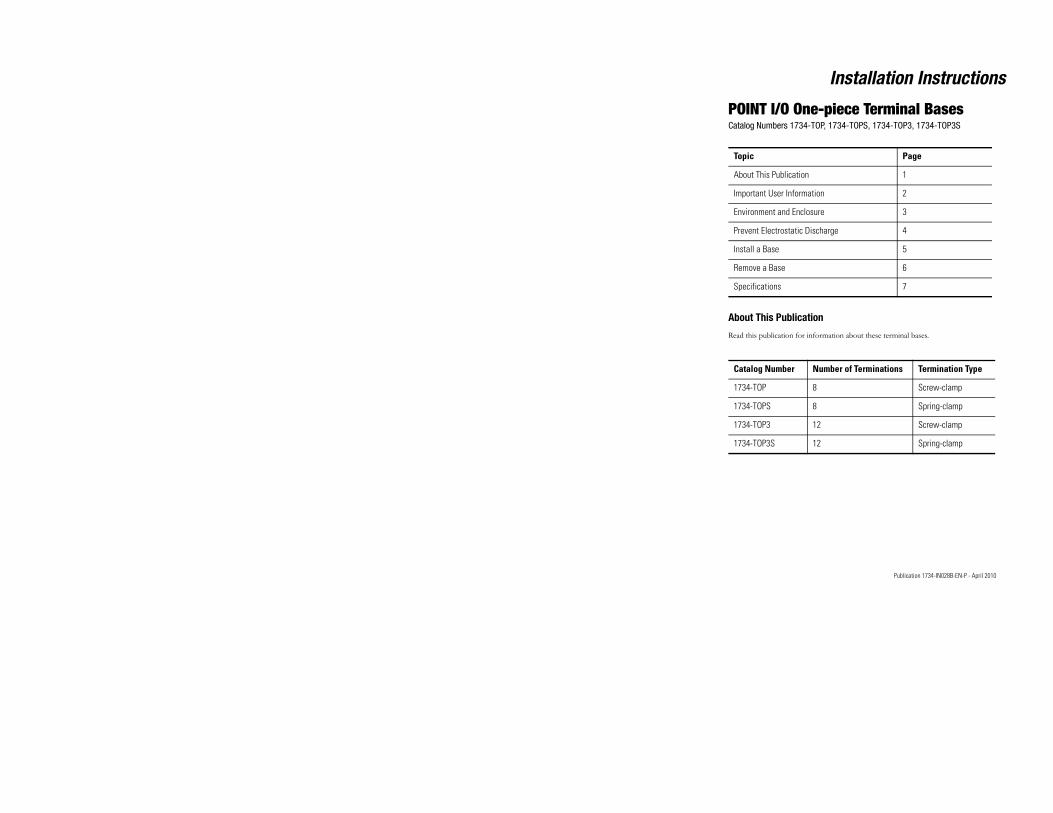
POINT I/O One-piece Terminal BasesCatalog Numbers 1734-TOP, 1734-TOPS, 1734-TOP3, 1734-TOP3S
About This Publication
Topic Page
About This Publication 1
Important User Information 2
Environment and Enclosure 3
Prevent Electrostatic Discharge 4
Install a Base 5
Remove a Base 6
Specifications 7
Publication 1734-IN028B-EN-P - April 2010
Read this publication for information about these terminal bases.
Catalog Number Number of Terminations Termination Type
1734-TOP 8 Screw-clamp
1734-TOPS 8 Spring-clamp
1734-TOP3 12 Screw-clamp
1734-TOP3S 12 Spring-clamp
2 POINT I/O One-piece Terminal Bases
Publication 1734-IN028B-EN-P - April 2010
Important User Information
Solid state equipment has operational characteristics differing from those of electromechanical equipment. Safety Guidelines for the Application, Installation and Maintenance of Solid State Controls (publication SGI-1.1 available from your local Rockwell Automation sales office or online at http://literature.rockwellautomation.com) describes some important differences between solid state equipment and hard-wired electromechanical devices. Because of this difference, and also because of the wide variety of uses for solid state equipment, all persons responsible for applying this equipment must satisfy themselves that each intended application of this equipment is acceptable. In no event will Rockwell Automation, Inc. be responsible or liable for indirect or consequential damages resulting from the use or application of this equipment. The examples and diagrams in this manual are included solely for illustrative purposes. Because of the many variables and requirements associated with any particular installation, Rockwell Automation, Inc. cannot assume responsibility or liability for actual use based on the examples and diagrams.No patent liability is assumed by Rockwell Automation, Inc. with respect to use of information, circuits, equipment, or software described in this manual. Reproduction of the contents of this manual, in whole or in part, without written permission of Rockwell Automation, Inc., is prohibited. Throughout this manual, when necessary, we use notes to make you aware of safety considerations.
WARNING Identifies information about practices or circumstances that can cause an explosion in a hazardous environment, which may lead to personal injury or death, property damage, or economic loss.
IMPORTANT Identifies information that is critical for successful application and understanding of the product.
POINT I/O One-piece Terminal Bases 3
Environment and Enclosure
IMPORTANTIdentifies information about practices or circumstances that can lead to personal injury or death, property damage, or economic loss. Attentions help you to identify a hazard, avoid a hazard and recognize the consequences.
SHOCK HAZARDLabels may be located on or inside the equipment, for example, a drive or motor, to alert people that dangerous voltage may be present.
BURN HAZARDLabels may be located on or inside the equipment, for example, a drive or motor, to alert people that surfaces may be dangerous temperatures.
ATTENTION This equipment is intended for use in a Pollution Degree 2 industrial environment, in overvoltage Category II applications (as defined in IEC 60664-1), at altitudes up to 2000 m (6562 ft) without derating.
This equipment is considered Group 1, Class A industrial equipment according to IEC/CISPR 11. Without appropriate precautions, there may be difficulties with electromagnetic
Publication 1734-IN028B-EN-P - April 2010
compatibility in residential and other environments due to conducted and radiated disturbances. This equipment is supplied as open-type equipment. It must be mounted within an enclosure that is suitably designed for those specific environmental conditions that will be present and appropriately designed to prevent personal injury resulting from accessibility to live parts. The enclosure must have suitable flame-retardant properties to prevent or minimize the spread of flame, complying with a flame spread rating of 5VA, V2, V1, V0 (or equivalent) if non-metallic. The interior of the enclosure must be accessible only by the use of a tool. Subsequent sections of this publication may contain additional information regarding specific enclosure type ratings that are required to comply with certain product safety certifications. In addition to this publication, see:• Industrial Automation Wiring and Grounding Guidelines,
Rockwell Automation publication 1770-4.1, for additional installation requirements.
• NEMA Standard 250 and IEC 60529, as applicable, for explanations of the degrees of protection provided by different types of enclosure.
4 POINT I/O One-piece Terminal Bases
Publication 1734-IN028B-EN-P - April 2010
Prevent Electrostatic Discharge
ATTENTION This equipment is sensitive to electrostatic discharge, which can cause internal damage and affect normal operation. Follow these guidelines when you handle this equipment:
• Touch a grounded object to discharge potential static.
• Wear an approved grounding wriststrap.
• Do not touch connectors or pins on component boards.
• Do not touch circuit components inside the equipment.
• Use a static-safe workstation, if available.
• Store the equipment in appropriate static-safe packaging when not in use.
ATTENTION POINT I/O is grounded through the DIN rail to chassis ground. Use zinc plated yellow-chromate steel DIN rail to assure proper grounding.
The use of other DIN rail materials (for example, aluminum or plastic) that can corrode, oxidize, or are poor conductors, can result in improper or intermittent grounding.
Secure DIN rail to mounting surface approximately every 200 mm (7.8 in.) and use end-anchors appropriately.
ATTENTION
Do not wire more than 2 conductors on any single terminal.
POINT I/O One-piece Terminal Bases 5
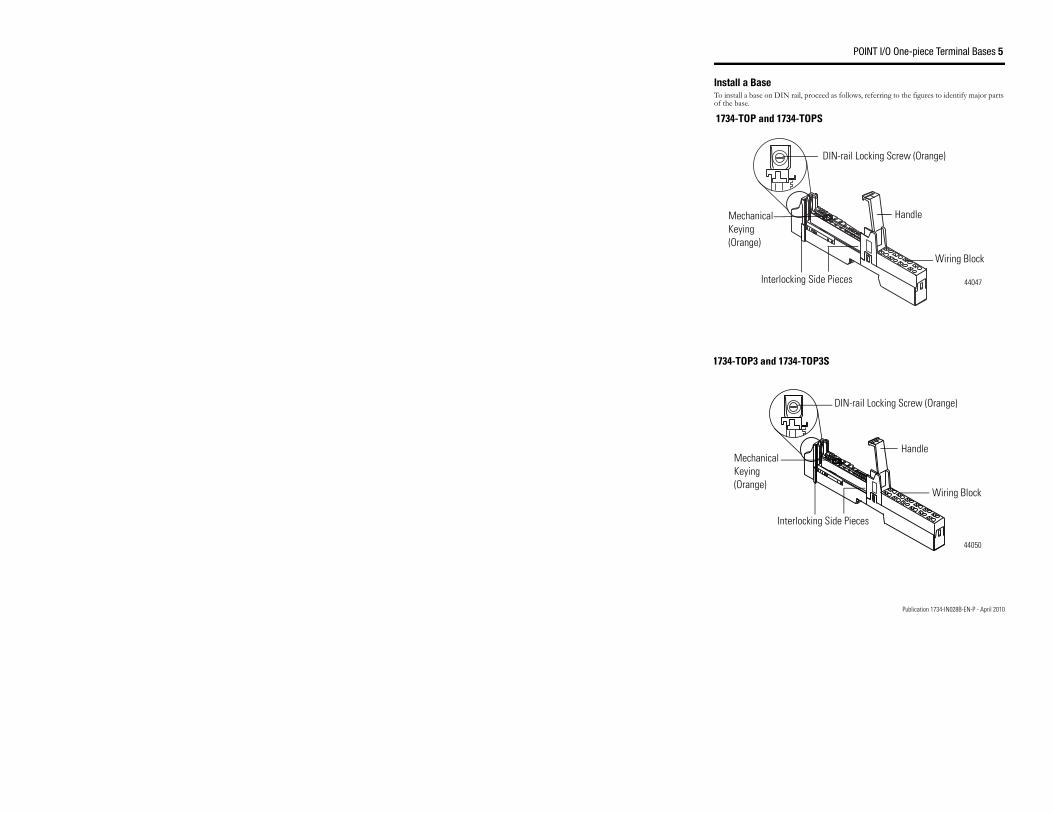
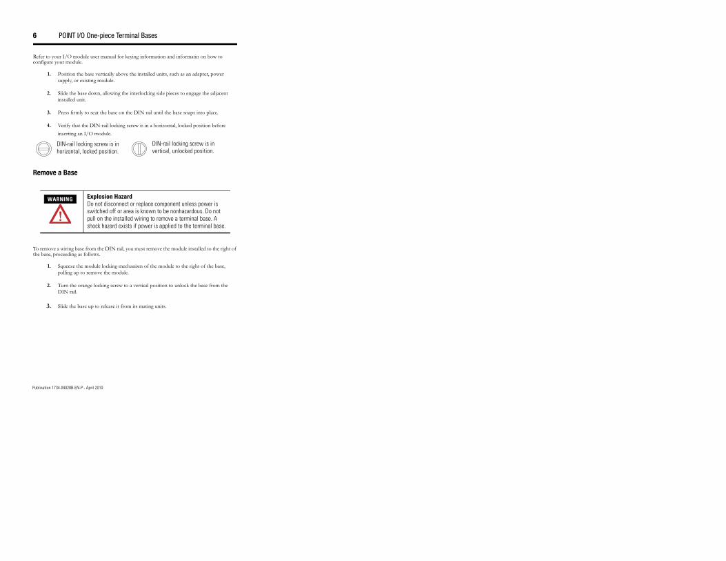
Install a Base To install a base on DIN rail, proceed as follows, referring to the figures to identify major parts of the base.
Wiring Block
Mechanical Keying (Orange)
44047
1734-TOP and 1734-TOPS
DIN-rail Locking Screw (Orange)
Handle
Interlocking Side Pieces
Publication 1734-IN028B-EN-P - April 2010
44050
Wiring Block
DIN-rail Locking Screw (Orange)
Mechanical Keying (Orange)
Handle
Interlocking Side Pieces
1734-TOP3 and 1734-TOP3S
6 POINT I/O One-piece Terminal Bases
Publication 1734-IN028B-EN-P - April 2010
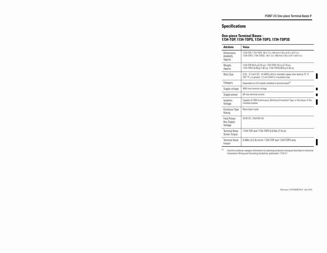
Refer to your I/O module user manual for keying information and informatin on how to configure your module.
1. Position the base vertically above the installed units, such as an adapter, power supply, or existing module.
2. Slide the base down, allowing the interlocking side pieces to engage the adjacent installed unit.
3. Press firmly to seat the base on the DIN rail until the base snaps into place.
4. Verify that the DIN-rail locking screw is in a horizontal, locked position before inserting an I/O module.
Remove a Base
To remove a wiring base from the DIN rail, you must remove the module installed to the right of the base, proceeding as follows.
1. Squeeze the module locking mechanism of the module to the right of the base, pulling up to remove the module.
2. Turn the orange locking screw to a vertical position to unlock the base from the DIN rail.
3. Slide the base up to release it from its mating units.
WARNING Explosion Hazard Do not disconnect or replace component unless power is switched off or area is known to be nonhazardous. Do not pull on the installed wiring to remove a terminal base. A shock hazard exists if power is applied to the terminal base.
DIN-rail locking screw is in horizontal, locked position.
DIN-rail locking screw is in vertical, unlocked position.
POINT I/O One-piece Terminal Bases 7
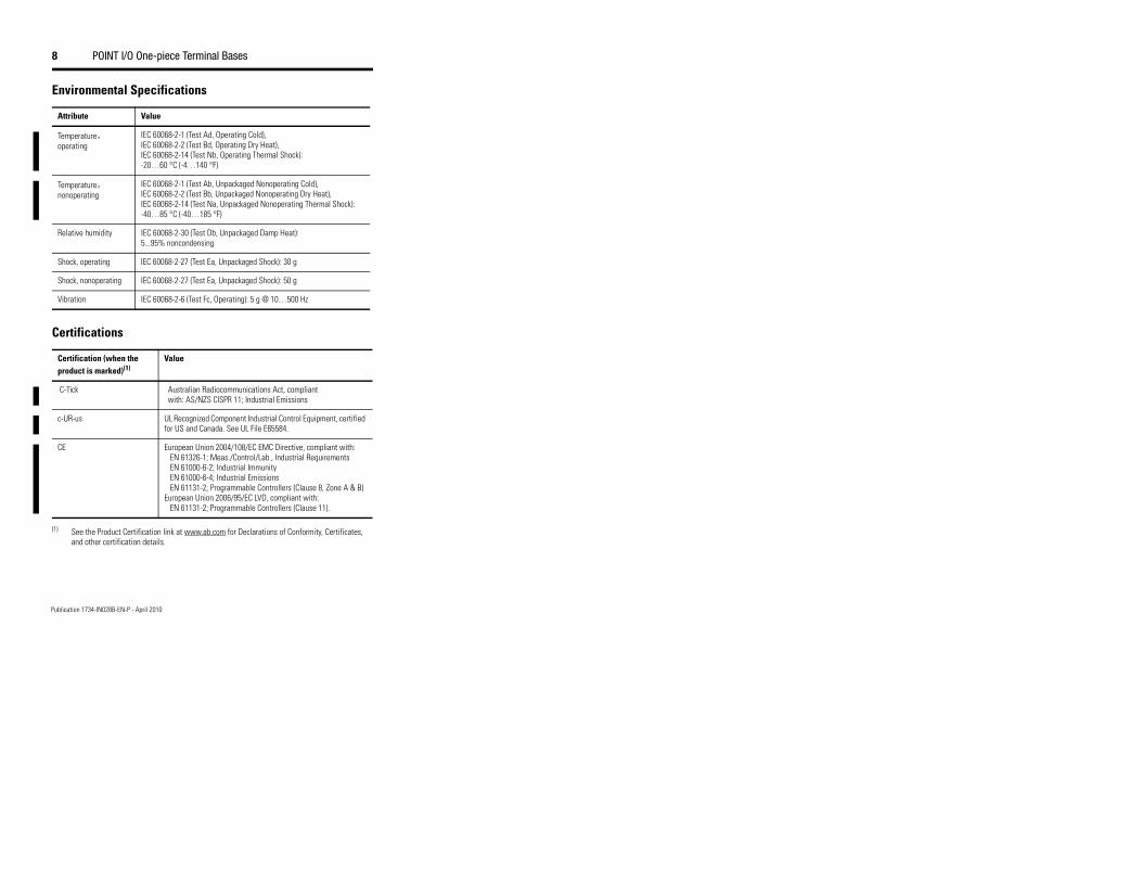
Specifications
One-piece Terminal Bases - 1734-TOP, 1734-TOPS, 1734-TOP3, 1734-TOP3S
Attribute Value
Dimensions (HxWxD), Approx.
1734-TOP, 1734-TOPS 49 x 12 x 144 mm (1.93 x 0.47 x 5.67 in.) 1734-TOP3, 1734-TOP3S 49 x 12 x 168 mm (1.93 x 0.47 x 6.61 in.)
Weight, Approx.
1734-TOP 63.8 g (2.25 oz), 1734-TOP3 79.2 g (2.79 oz), 1734-TOPS 55.68 g (1.96 oz), 1734-TOP3S 66.8 g (2.36 oz)
Wire Size 0.25... 2.5 mm² (22...14 AWG) solid or stranded copper wire rated at 75 °C (167 °F ), or greater, 1.2 mm (3/64 in.) insulation max
Category Dependent on I/O module installed in terminal base(1)
Supply voltage 300V max terminal voltage
Supply power 8A max terminal current
Isolation Voltage
Capable of 240V (continuous), Reinforced Insulation Type, or the lesser of the installed module.
Publication 1734-IN028B-EN-P - April 2010
(1) Use this conductor category information for planning conductor routing as described in Industrial Automation Wiring and Grounding Guidelines, publication 1770-4.1.
Enclosure Type Rating
None (open-style)
Field Power Bus Supply Voltage
28.8V DC, 120/240V AC
Terminal Base Screw Torque
1734-TOP and 1734-TOP3 0.6 Nm (7 lb-in)
Terminal block torque
0.4Nm (3.5 lb-in) for 1734-TOP and 1734-TOP3 only
8 POINT I/O One-piece Terminal Bases
Publication 1734-IN028B-EN-P - April 2010
Environmental Specifications
Attribute Value
Temperature, operating
IEC 60068-2-1 (Test Ad, Operating Cold), IEC 60068-2-2 (Test Bd, Operating Dry Heat), IEC 60068-2-14 (Test Nb, Operating Thermal Shock): -20…60 °C (-4…140 °F)
Temperature, nonoperating
IEC 60068-2-1 (Test Ab, Unpackaged Nonoperating Cold), IEC 60068-2-2 (Test Bb, Unpackaged Nonoperating Dry Heat), IEC 60068-2-14 (Test Na, Unpackaged Nonoperating Thermal Shock): -40…85 °C (-40…185 °F)
Relative humidity IEC 60068-2-30 (Test Db, Unpackaged Damp Heat): 5...95% noncondensing
Shock, operating IEC 60068-2-27 (Test Ea, Unpackaged Shock): 30 g
Shock, nonoperating IEC 60068-2-27 (Test Ea, Unpackaged Shock): 50 g
Vibration IEC 60068-2-6 (Test Fc, Operating): 5 g @ 10…500 Hz
Certifications
Certification (when the product is marked)(1)
Value
C-Tick Australian Radiocommunications Act, compliant with: AS/NZS CISPR 11; Industrial Emissions
c-UR-us UL Recognized Component Industrial Control Equipment, certified for US and Canada. See UL File E65584.
CE European Union 2004/108/EC EMC Directive, compliant with: EN 61326-1; Meas./Control/Lab., Industrial Requirements EN 61000-6-2; Industrial Immunity EN 61000-6-4; Industrial Emissions EN 61131-2; Programmable Controllers (Clause 8, Zone A & B) European Union 2006/95/EC LVD, compliant with: EN 61131-2; Programmable Controllers (Clause 11).
(1) See the Product Certification link at www.ab.com for Declarations of Conformity, Certificates, and other certification details.

POINT I/O One-piece Terminal Bases 9
Notes:
Publication 1734-IN028B-EN-P - April 2010

10 POINT I/O One-piece Terminal Bases
Publication 1734-IN028B-EN-P - April 2010
Notes:
POINT I/O One-piece Terminal Bases 11
Notes:
Publication 1734-IN028B-EN-P - April 2010
Publication 1734-IN028B-EN-P - April 2010 PN 75026Supersedes Publication 1734-IN028A-EN-P - February 2006Copyright © 2010 Rockwell Automation, Inc. All rights reserved. Printed in the U.S.A
Allen-Bradley, POINT I/O, and Rockwell Automation are trademarks of Rockwell Automation, Inc. Trademarks not belonging to Rockwell Automation are property of their respective companies.