1797-in028b-en-e armorpoint i/o 2-port ethernet/ip adapter
TRANSCRIPT
Installation Instructions
ArmorPoint I/O 2-Port EtherNet/IP Adapter, Series A
Catalog Number 1738-AENTR
Topic Page
Important User Information 2
Environment and Enclosure 3
Prevent Electrostatic Discharge 3
About the Module 4
Mount the Adapter and I/O Base 7
Set the Network Address 9
Wire the EtherNet/IP Adapter 10
Interpret the Status Indicators 11
Specifications 16
2 ArmorPoint I/O 2-Port EtherNet/IP Adapter, Series A
Important User Information
Solid state equipment has operational characteristics differing from those of electromechanical equipment. Safety Guidelines for the Application, Installation and Maintenance of Solid State Controls (Publication SGI-1.1 available from your local Rockwell Automation sales office or online at http://literature.rockwellautomation.com) describes some important differences between solid state equipment and hard-wired electromechanical devices. Because of this difference, and also because of the wide variety of uses for solid state equipment, all persons responsible for applying this equipment must satisfy themselves that each intended application of this equipment is acceptable.
In no event will Rockwell Automation, Inc. be responsible or liable for indirect or consequential damages resulting from the use or application of this equipment.
The examples and diagrams in this manual are included solely for illustrative purposes. Because of the many variables and requirements associated with any particular installation, Rockwell Automation, Inc. cannot assume responsibility or liability for actual use based on the examples and diagrams.
No patent liability is assumed by Rockwell Automation, Inc. with respect to use of information, circuits, equipment, or software described in this manual.
Reproduction of the contents of this manual, in whole or in part, without written permission of Rockwell Automation, Inc., is prohibited.
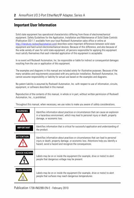
Throughout this manual, when necessary, we use notes to make you aware of safety considerations.
WARNING Identifies information about practices or circumstances that can cause an explosion in a hazardous environment, which may lead to personal injury or death, property damage, or economic loss.
IMPORTANT Identifies information that is critical for successful application and understanding of the product.
ATTENTION Identifies information about practices or circumstances that can lead to personal injury or death, property damage, or economic loss. Attentions help you identify a hazard, avoid a hazard and recognize the consequences.
SHOCK HAZARDLabels may be on or inside the equipment (for example, drive or motor) to alert people that dangerous voltage may be present.
BURN HAZARDLabels may be on or inside the equipment (for example, drive or motor) to alert people that surfaces may reach dangerous temperatures.
Publication 1738-IN028B-EN-E - February 2010
ArmorPoint I/O 2-Port EtherNet/IP Adapter, Series A 3
Environment and Enclosure
Prevent Electrostatic Discharge
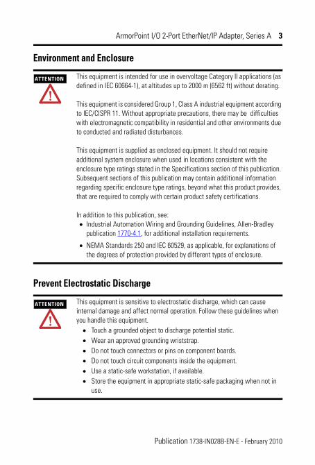
ATTENTION This equipment is intended for use in overvoltage Category II applications (as defined in IEC 60664-1), at altitudes up to 2000 m (6562 ft) without derating.
This equipment is considered Group 1, Class A industrial equipment according to IEC/CISPR 11. Without appropriate precautions, there may be difficulties with electromagnetic compatibility in residential and other environments due to conducted and radiated disturbances.
This equipment is supplied as enclosed equipment. It should not require additional system enclosure when used in locations consistent with the enclosure type ratings stated in the Specifications section of this publication. Subsequent sections of this publication may contain additional information regarding specific enclosure type ratings, beyond what this product provides, that are required to comply with certain product safety certifications.
In addition to this publication, see:• Industrial Automation Wiring and Grounding Guidelines, Allen-Bradley
publication 1770-4.1, for additional installation requirements.
• NEMA Standards 250 and IEC 60529, as applicable, for explanations of the degrees of protection provided by different types of enclosure.
ATTENTION This equipment is sensitive to electrostatic discharge, which can cause internal damage and affect normal operation. Follow these guidelines when you handle this equipment.
• Touch a grounded object to discharge potential static.• Wear an approved grounding wriststrap.• Do not touch connectors or pins on component boards.• Do not touch circuit components inside the equipment.• Use a static-safe workstation, if available.• Store the equipment in appropriate static-safe packaging when not in
use.
Publication 1738-IN028B-EN-E - February 2010
4 ArmorPoint I/O 2-Port EtherNet/IP Adapter, Series A
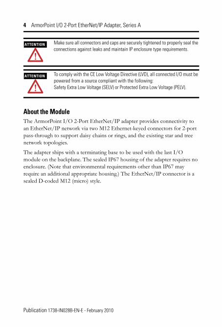
About the ModuleThe ArmorPoint I/O 2-Port EtherNet/IP adapter provides connectivity to an EtherNet/IP network via two M12 Ethernet-keyed connectors for 2-port pass-through to support daisy chains or rings, and the existing star and tree network topologies.
The adapter ships with a terminating base to be used with the last I/O module on the backplane. The sealed IP67 housing of the adapter requires no enclosure. (Note that environmental requirements other than IP67 may require an additional appropriate housing.) The EtherNet/IP connector is a sealed D-coded M12 (micro) style.
ATTENTION Make sure all connectors and caps are securely tightened to properly seal the connections against leaks and maintain IP enclosure type requirements.
ATTENTION To comply with the CE Low Voltage Directive (LVD), all connected I/O must be powered from a source compliant with the following:Safety Extra Low Voltage (SELV) or Protected Extra Low Voltage (PELV).
Publication 1738-IN028B-EN-E - February 2010

ArmorPoint I/O 2-Port EtherNet/IP Adapter, Series A 5
1738-AENTR Adapter, Series A
Before You BeginTo effectively use your adapter, note the following considerations.
Determine Compatibility
RSLogix 5000 version 17 or greater must be used for the 1738-AENTR’s Add-on Profile. The 1738-AENTR adapters will accept I/O connections with the electronic keying for the 1738-AENT. This allows the 1738-AENTR adapter to be used in a daisy-chain topology with the 1738-AENT’s profile used for the 1738-AENTR.
1738-AENTR
EtherNet I/P
AdapterStatus
NetworkActivity
NetworkStatus
PointBusStatus
SystemPower
AdapterPower
conformance tested
™
PWR
IP ADDRESS
Link 2Activity/Status
Link 1Activity/Status
44830
M12 connectors
Auxiliary Power
connector
Network address
switchesStatus indicators
Publication 1738-IN028B-EN-E - February 2010

6 ArmorPoint I/O 2-Port EtherNet/IP Adapter, Series A
If using the adapter with a 1756-ENBT module, 1768-ENBT module or an L3xE processor, use the following required firmware versions for these bridge modules:
• 1756-ENBT firmware version 4.5 or greater• 1768-ENBT firmware version 2.1 or greater• L3xE processor firmware version 17 or greater
If you use the BootP utility to assign IP addresses to the adapter, use version 2.3.2 or greater.
Understand Messaging
Class 3 (Explicit Message) requests through the adapter to a specific I/O module may not always receive a response from the I/O module. In the case where the I/O module does not reply to the request, the adapter responds with an error code indicating a time-out.
Establish I/O Connections
When you power up an ArmorPoint I/O system and establish I/O connections, the outputs transition to the Idle state, applying Idle state data before going to RUN mode. This occurs even when the controller making the connection is already in RUN mode.
Configure Autobaud
The adapter cannot reconfigure an I/O module that you previously configured to operate at a fixed baud rate. When you reuse an ArmorPoint I/O module from another ArmorPoint I/O system, configure the module to autobaud before using it with the adapter.
Publication 1738-IN028B-EN-E - February 2010
ArmorPoint I/O 2-Port EtherNet/IP Adapter, Series A 7
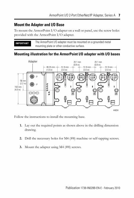
Mount the Adapter and I/O BaseTo mount the ArmorPoint I/O adapter on a wall or panel, use the screw holes provided with the ArmorPoint I/O adapter.
Mounting illustration for the ArmorPoint I/O adapter with I/O bases
Follow the instructions to install the mounting base.
1. Lay out the required points as shown above in the drilling dimension drawing.
2. Drill the necessary holes for M4 (#8) machine or self-tapping screws.
3. Mount the adapter using M4 (#8) screws.
IMPORTANT The ArmorPoint I/O adapter must be mounted on a grounded metal mounting plate or other conductive surface.
Adapter
102 mm (4.0 in)
56 mm (2.2 in)
46.25 mm (1.8 in)
51.9 mm (2.0 in)
20.1 mm (0.8 in)
20.1 mm (0.8 in)
51.9 mm (2.0 in)
51.9 mm (2.0 in)
44834
Publication 1738-IN028B-EN-E - February 2010
8 ArmorPoint I/O 2-Port EtherNet/IP Adapter, Series A
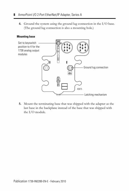
4. Ground the system using the ground lug connection in the I/O base. (The ground lug connection is also a mounting hole.)
5. Mount the terminating base that was shipped with the adapter as the last base in the backplane instead of the base that was shipped with the I/O module.
Ground lug connection
Latching mechanism
Set to keyswitch position to 4 for the 1738 analog output modules
43675
Mounting base
Publication 1738-IN028B-EN-E - February 2010
ArmorPoint I/O 2-Port EtherNet/IP Adapter, Series A 9
Set the Network AddressThe adapter ships with the rotary network address switches set to 999 and DHCP enabled. To change the network address, you can:
• adjust the switches on the front of the module• use a Dynamic Host Configuration Protocol (DHCP) server, such as
Rockwell Automation BootP/DHCP• retrieve the IP address from nonvolatile memory
The adapter reads the switches first to determine if the switches are set to a valid number. Set the network address by adjusting the three switches on the front of the module.
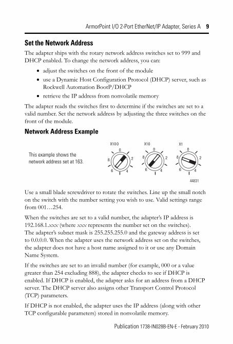
Network Address Example
Use a small blade screwdriver to rotate the switches. Line up the small notch on the switch with the number setting you wish to use. Valid settings range from 001…254.
When the switches are set to a valid number, the adapter’s IP address is 192.168.1.xxx (where xxx represents the number set on the switches). The adapter’s subnet mask is 255.255.255.0 and the gateway address is set to 0.0.0.0. When the adapter uses the network address set on the switches, the adapter does not have a host name assigned to it or use any Domain Name System.
If the switches are set to an invalid number (for example, 000 or a value greater than 254 excluding 888), the adapter checks to see if DHCP is enabled. If DHCP is enabled, the adapter asks for an address from a DHCP server. The DHCP server also assigns other Transport Control Protocol (TCP) parameters.
If DHCP is not enabled, the adapter uses the IP address (along with other TCP configurable parameters) stored in nonvolatile memory.
This example shows the network address set at 163.
44831
Publication 1738-IN028B-EN-E - February 2010
10 ArmorPoint I/O 2-Port EtherNet/IP Adapter, Series A
Refer to publication 1738-UM014, ArmorPoint I/O EtherNet/IP Adapter User Manual, for more information.
Wire the EtherNet/IP AdapterFollowing are wiring instructions for the ArmorPoint EtherNet/IP adapter.
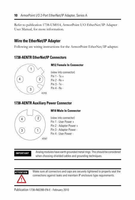
1738-AENTR EtherNet/IP Connectors
1738-AENTR Auxiliary Power Connector
IMPORTANT Analog modules have earth grounded metal rings. This should be considered when choosing shielded cables and grounding techniques.
ATTENTION Make sure all connectors and caps are securely tightened to properly seal the connections against leaks and maintain IP enclosure type requirements.
(view into connector) Pin 1 - Tx + Pin 2 - Rx + Pin 3 - Tx - Pin 4 - Rx -
M12 Female In Connector
43765
(view into connector) Pin 1 - User Power + Pin 2 - Adapter Power + Pin 3 - Adapter Power - Pin 4 - User Power -
43587
M18 Male In Connector
Publication 1738-IN028B-EN-E - February 2010

ArmorPoint I/O 2-Port EtherNet/IP Adapter, Series A 11
Interpret the Status Indicators
Adapter Status
Status Description Recommended action
Off No power applied to device. Apply power to device.
Green Device operating normally. None.
Flashing red/green
Device is in self-test. None.
Flashing red Recoverable fault has occurred: - Firmware (NVS) update. - Address switches changed.
- Complete firmware update. - Verify address switches.
Adapter Status indicatorNetwork Activity indicatorNetwork Status indicator
System Power indicatorAdapter Power indicator
PointBus Status indicator
1738-AENTR
EtherNet I/P
AdapterStatus
NetworkActivity
NetworkStatus
PointBusStatus
SystemPower
AdapterPower
conformance tested
™
PWR
IP ADDRESS
Link 2Activity/Status
Link 1Activity/Status
44830
Link 1 Activity/Status indicator
Link 2 Activity/Status indicator
Publication 1738-IN028B-EN-E - February 2010
12 ArmorPoint I/O 2-Port EtherNet/IP Adapter, Series A
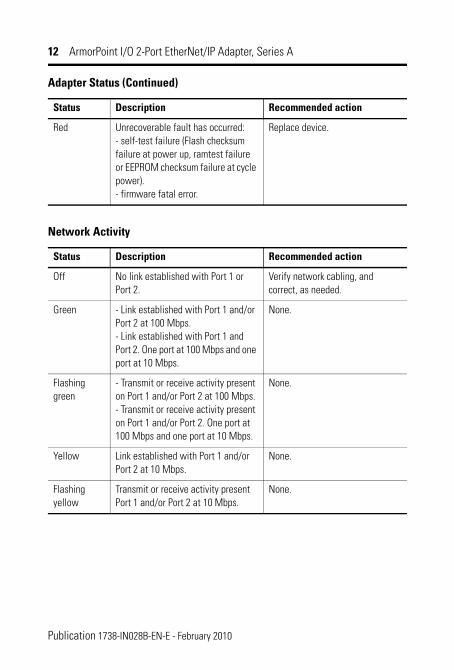
Red Unrecoverable fault has occurred: - self-test failure (Flash checksum failure at power up, ramtest failure or EEPROM checksum failure at cycle power). - firmware fatal error.
Replace device.
Network Activity
Status Description Recommended action
Off No link established with Port 1 or Port 2.
Verify network cabling, and correct, as needed.
Green - Link established with Port 1 and/or Port 2 at 100 Mbps. - Link established with Port 1 and Port 2. One port at 100 Mbps and one port at 10 Mbps.
None.
Flashing green
- Transmit or receive activity present on Port 1 and/or Port 2 at 100 Mbps. - Transmit or receive activity present on Port 1 and/or Port 2. One port at 100 Mbps and one port at 10 Mbps.
None.
Yellow Link established with Port 1 and/or Port 2 at 10 Mbps.
None.
Flashing yellow
Transmit or receive activity present Port 1 and/or Port 2 at 10 Mbps.
None.
Adapter Status (Continued)
Status Description Recommended action
Publication 1738-IN028B-EN-E - February 2010
ArmorPoint I/O 2-Port EtherNet/IP Adapter, Series A 13
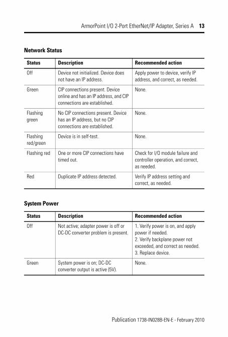
Network Status
Status Description Recommended action
Off Device not initialized. Device does not have an IP address.
Apply power to device, verify IP address, and correct, as needed.
Green CIP connections present. Device online and has an IP address, and CIP connections are established.
None.
Flashing green
No CIP connections present. Device has an IP address, but no CIP connections are established.
None.
Flashing red/green
Device is in self-test. None.
Flashing red One or more CIP connections have timed out.
Check for I/O module failure and controller operation, and correct, as needed.
Red Duplicate IP address detected. Verify IP address setting and correct, as needed.
System Power
Status Description Recommended action
Off Not active; adapter power is off or DC-DC converter problem is present.
1. Verify power is on, and apply power if needed. 2. Verify backplane power not exceeded, and correct as needed. 3. Replace device.
Green System power is on; DC-DC converter output is active (5V).
None.
Publication 1738-IN028B-EN-E - February 2010
14 ArmorPoint I/O 2-Port EtherNet/IP Adapter, Series A
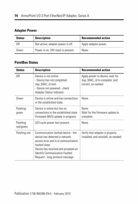
Adapter Power
Status Description Recommended action
Off Not active; adapter power is off. Apply adapter power.
Green Power is on; 24V input is present. None.
PointBus Status
Status Description Recommended action
Off Device is not online. - Device has not completed dup_MAC_id test. - Device not powered - check Adapter Status indicator.
Apply power to device, wait for dup_MAC_id to complete, and correct, as needed.
Green Device is online and has connections in the established state.
None.
Flashing green
Device is online but has no connections in the established state. Firmware (NVS) update in progress.
None. Wait for the firmware update to complete.
Flashing red/green
LED cycle power test present. None.
Flashing red Communication faulted device - the device has detected a network access error and is in communication faulted state. Device has received and accepted an Identify Communication Faulted Request - long protocol message.
Verify that adapter is properly installed, and reinstall, as needed.
Publication 1738-IN028B-EN-E - February 2010
ArmorPoint I/O 2-Port EtherNet/IP Adapter, Series A 15
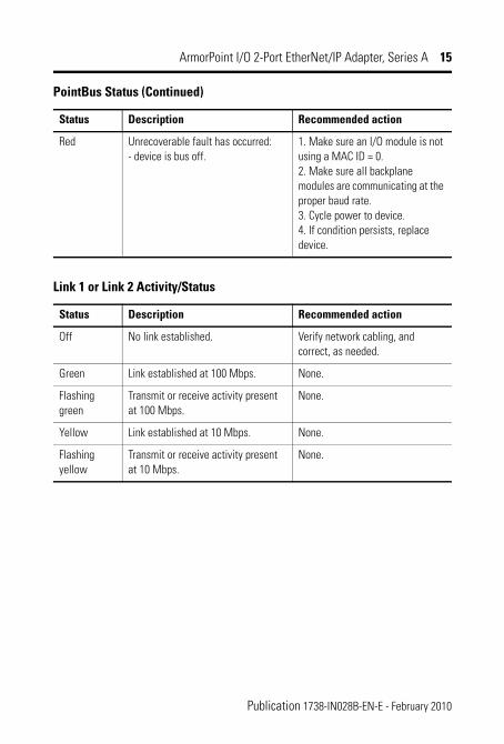
Red Unrecoverable fault has occurred: - device is bus off.
1. Make sure an I/O module is not using a MAC ID = 0. 2. Make sure all backplane modules are communicating at the proper baud rate. 3. Cycle power to device. 4. If condition persists, replace device.
Link 1 or Link 2 Activity/Status
Status Description Recommended action
Off No link established. Verify network cabling, and correct, as needed.
Green Link established at 100 Mbps. None.
Flashing green
Transmit or receive activity present at 100 Mbps.
None.
Yellow Link established at 10 Mbps. None.
Flashing yellow
Transmit or receive activity present at 10 Mbps.
None.
PointBus Status (Continued)
Status Description Recommended action
Publication 1738-IN028B-EN-E - February 2010

16 ArmorPoint I/O 2-Port EtherNet/IP Adapter, Series A
Specifications
General
Attribute Value
Number of modules supported, maximum
63
Number of rack optimized connections
5 (for digital modules only)
Number of direct connections, maximum
20
Backplane output current, maximum
0.8 A The actual number of modules can vary. Add up the requirements of the modules you want to use, for current, to make sure they do not exceed the amperage limit of 0.8 A for the 1738-AENTR. Backplane current can be extended beyond 0.8 A by using a 1738-EP24DC Backplane Extension Power Supply. Add multiple 1738-EP24DC modules to achieve the maximum limit of 63 modules.
Input voltage rating 24V DC nominal 10…28.8V DC range
Field side power requirements 24V DC (+20% = 28.8 V DC maximum) @ 400 mA maximum
Inrush current, maximum 6 A for 10 ms
Interruption Output voltage will stay within specifications when input drops out for 10 ms at 10V with maximum load.
Input overvoltage protection Reverse polarity protected
PointBus output current, maximum 0.8 A @ 5V DC ± 5% (4.75…5.25V DC)
Auxiliary power cable(1) Standard cordset (single-ended): Allen-Bradley part number 889N-F4AFC-yF Standard patchcord (double-ended): Allen-Bradley part number 889N-F4AFNM-x
Publication 1738-IN028B-EN-E - February 2010
ArmorPoint I/O 2-Port EtherNet/IP Adapter, Series A 17
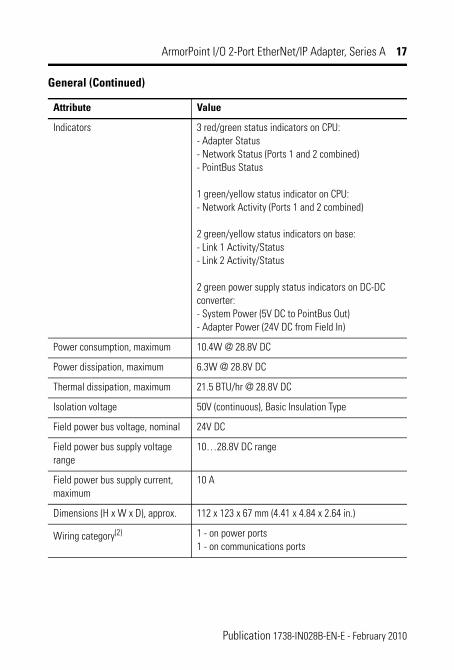
Indicators 3 red/green status indicators on CPU: - Adapter Status - Network Status (Ports 1 and 2 combined) - PointBus Status
1 green/yellow status indicator on CPU: - Network Activity (Ports 1 and 2 combined)
2 green/yellow status indicators on base: - Link 1 Activity/Status - Link 2 Activity/Status
2 green power supply status indicators on DC-DC converter: - System Power (5V DC to PointBus Out) - Adapter Power (24V DC from Field In)
Power consumption, maximum 10.4W @ 28.8V DC
Power dissipation, maximum 6.3W @ 28.8V DC
Thermal dissipation, maximum 21.5 BTU/hr @ 28.8V DC
Isolation voltage 50V (continuous), Basic Insulation Type
Field power bus voltage, nominal 24V DC
Field power bus supply voltage range
10…28.8V DC range
Field power bus supply current, maximum
10 A
Dimensions (H x W x D), approx. 112 x 123 x 67 mm (4.41 x 4.84 x 2.64 in.)
Wiring category(2) 1 - on power ports 1 - on communications ports
General (Continued)
Attribute Value
Publication 1738-IN028B-EN-E - February 2010

18 ArmorPoint I/O 2-Port EtherNet/IP Adapter, Series A
Weight, approx. 0.33 kg (0.72 lb)
Mounting type Metal panel
Enclosure type rating Meets IP65/66/67/69K (when marked)
(1) Refer to publication M116-CA001A-EN-P for more information.
(2) Use this Conductor Category information for planning conductor routing. Refer to Industrial Automation Wiring and Grounding Guidelines, publication 1770-4.1.
Specifications for Ethernet Communication
Attribute Value
Ethernet communication rate 10/100 Mbps, half or full-duplex
Ethernet ports 2, configured as Embedded Switch
Ethernet network topologies supported
Star, Tree, Daisy chain/Linear, and Ring
Ethernet connector M12, D code, female, with Ethernet keying
Ethernet cable Category 5: Shielded or unshielded
General (Continued)
Attribute Value
Publication 1738-IN028B-EN-E - February 2010
ArmorPoint I/O 2-Port EtherNet/IP Adapter, Series A 19
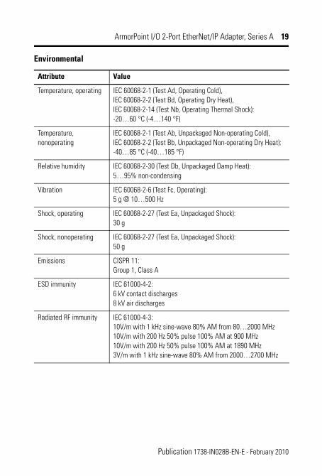
Environmental
Attribute Value
Temperature, operating IEC 60068-2-1 (Test Ad, Operating Cold), IEC 60068-2-2 (Test Bd, Operating Dry Heat), IEC 60068-2-14 (Test Nb, Operating Thermal Shock): -20…60 °C (-4…140 °F)
Temperature, nonoperating
IEC 60068-2-1 (Test Ab, Unpackaged Non-operating Cold), IEC 60068-2-2 (Test Bb, Unpackaged Non-operating Dry Heat): -40…85 °C (-40…185 °F)
Relative humidity IEC 60068-2-30 (Test Db, Unpackaged Damp Heat): 5…95% non-condensing
Vibration IEC 60068-2-6 (Test Fc, Operating): 5 g @ 10…500 Hz
Shock, operating IEC 60068-2-27 (Test Ea, Unpackaged Shock): 30 g
Shock, nonoperating IEC 60068-2-27 (Test Ea, Unpackaged Shock): 50 g
Emissions CISPR 11: Group 1, Class A
ESD immunity IEC 61000-4-2: 6 kV contact discharges 8 kV air discharges
Radiated RF immunity IEC 61000-4-3: 10V/m with 1 kHz sine-wave 80% AM from 80…2000 MHz 10V/m with 200 Hz 50% pulse 100% AM at 900 MHz 10V/m with 200 Hz 50% pulse 100% AM at 1890 MHz 3V/m with 1 kHz sine-wave 80% AM from 2000…2700 MHz
Publication 1738-IN028B-EN-E - February 2010
20 ArmorPoint I/O 2-Port EtherNet/IP Adapter, Series A
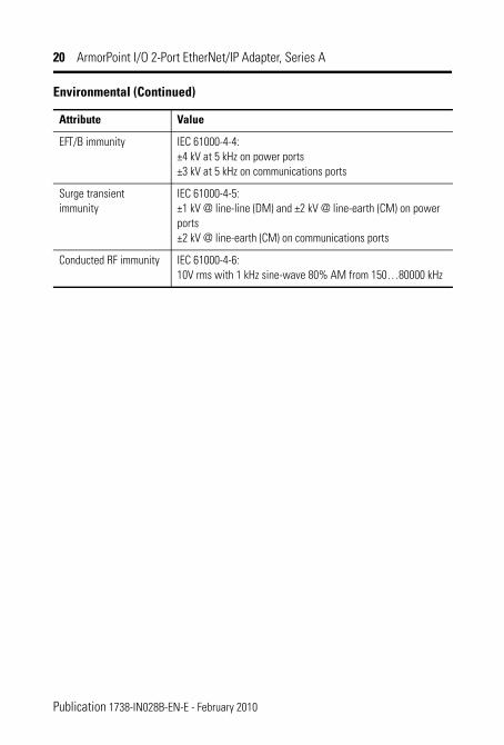
EFT/B immunity IEC 61000-4-4: ±4 kV at 5 kHz on power ports ±3 kV at 5 kHz on communications ports
Surge transient immunity
IEC 61000-4-5: ±1 kV @ line-line (DM) and ±2 kV @ line-earth (CM) on power ports ±2 kV @ line-earth (CM) on communications ports
Conducted RF immunity IEC 61000-4-6: 10V rms with 1 kHz sine-wave 80% AM from 150…80000 kHz
Environmental (Continued)
Attribute Value
Publication 1738-IN028B-EN-E - February 2010

ArmorPoint I/O 2-Port EtherNet/IP Adapter, Series A 21
Certifications
Certification (when
product is marked)(1)Value
CE European Union 2004/108/EC EMC Directive, compliant with: EN 61000-6-2; Industrial Immunity EN 61000-6-4; Industrial Emissions EN 61131-2; Programmable Controllers (Clause 8, Zone A & B) EN 61326-1; Meas./Control/Lab., Industrial Requirements
C-Tick Australian Radiocommunications Act, compliant with: AS/NZS CISPR 11; Industrial Emissions
EtherNet/IP ODVA conformance tested to EtherNet/IP specifications
(1) See the Product Certification link at http://www.ab.com for Declarations of Conformity, Certificates, and other certification details.
Publication 1738-IN028B-EN-E - February 2010

22 ArmorPoint I/O 2-Port EtherNet/IP Adapter, Series A
Notes:
Publication 1738-IN028B-EN-E - February 2010

ArmorPoint I/O 2-Port EtherNet/IP Adapter, Series A 23
Notes:
Publication 1738-IN028B-EN-E - February 2010

Publication 1738-IN028B-EN-E - February 2010
Rockwell Automation SupportRockwell Automation provides technical information on the Web to assist you in using its products. At http://support.rockwellautomation.com, you can find technical manuals, a knowledge base of FAQs, technical and application notes, sample code and links to software service packs, and a MySupport feature that you can customize to make the best use of these tools.
For an additional level of technical phone support for installation, configuration, and troubleshooting, we offer TechConnect support programs. For more information, contact your local distributor or Rockwell Automation representative, or visit http://support.rockwellautomation.com.
Installation AssistanceIf you experience a problem within the first 24 hours of installation, please review the information that's contained in this manual. You can also contact a special Customer Support number for initial help in getting your product up and running.
New Product Satisfaction ReturnRockwell Automation tests all of its products to ensure that they are fully operational when shipped from the manufacturing facility. However, if your product is not functioning and needs to be returned, follow these procedures.
Allen-Bradley, Rockwell Automation, TechConnect, and ArmorPoint are trademarks of Rockwell Automation, Inc. Trademarks not belonging to Rockwell Automation are property of their respective companies..
United States 1.440.646.3434 Monday – Friday, 8 a.m. – 5 p.m. EST
Outside United States Please contact your local Rockwell Automation representative for any technical support issues.
United States Contact your distributor. You must provide a Customer Support case number (see phone number above to obtain one) to your distributor in order to complete the return process.
Outside United States Please contact your local Rockwell Automation representative for the return procedure.
Supersedes Publication 1738-IN028A-EN-E - April 2009 Copyright © 2010 Rockwell Automation, Inc. All rights reserved.