1783 network computing terminal - welcome to visara ... · this version is being distributed under...
TRANSCRIPT

1783 Network Computing Terminal
User’s Manual
P/N 707042-002

ii 707042-002
The information contained in this document is subject to change without notice. Visara, Inc. makes no warranty of any kind withregard to this material including, but not limited to, the implied warranties of merchantability and fitness for a particularpurpose. Visara, Inc. shall not be liable for errors contained herein or for incidental or consequential damages in connection with thefurnishing, performance, or use of this material.
Safety and Regulatory Information
Safety
* UL1950, CSA950
* CE Mark, IEC950, EN60950, EU Low Voltage
Electro-Magnetic Interference
* This device complies with part 15 of the FCC rules. Operation is subject to the following 2 conditions: (1) This device may notcause harmful interference, and (2) this device must accept any interference received, including interference that may causeundesired operation.
Pursuant to part 15.21 of the FCC rules, any change or modification to this equipment not expressly approved by Visara, Inc. maycause harmful interference, and void your authority to operate this equipment.
* This apparatus complies with the CDoC CLASS “A” limits for radio interference as specified in the Canadian Department ofCommunications Radio Interference Regulations. Operation in a residential area may cause unacceptable interference to radioand TV reception requiring the owner or operator to take whatever steps are necessary to correct the interference.
✦ Cet appariel est conformé aux normes CDoC CLASS “A: D’Interference radio tel que specifier par le Ministère Canadiendes communications dans les règlements D” Interference Radio. Cet équipment ne dépasse pas les limites de Classe Bd’émission de bruits radioélectriques pour les appareils numériques, telles que prescrites par le Règlement sur le brouillageradioélectrique établi par le Ministère des Communications du Canada. L’exploitation faite en milieu résidentiel peut entraînerle brouillage des réceptions radio et télé, ce qui obligerait le propriétaire ou l’opérateur à prendre les dispositions nécessairespour en éliminer les causes.
✦ CE mark, EN50022, EN50082-1, EU EMC Directive
Patents, Trademarks and Acknowledgments
IBM and SNA are registered trademarks of International Business Machines Corporation.QNX and Photon microGUI are registered trademarks of QNX Software Systems Ltd.Voyager is a trademark of QNX Software Systems Ltd.Other trademarks are the properties of their respective owners.
Portions of the code and documentation described in this guide were derived from code and documentation developed under theauspices of the Regents of the University of California and have been acquired and modified under the provisions that the followingcopyright notice and permission notice appear:
©Copyright Regents of the University of Califormia, 1986, 1987. All rights reserved.
Redistribution and use in source and binary forms are permitted provided that this notice is preserved and that due credit is given theUniversity of Califormia at Berkeley. The name of the University may not be used to endorse or promote products derived from thissoftware without specific prior written permission. This software is provided “as is” without express or implied warranty.
NCSA Mosaic was developed by the National Center for Supercomputing Applications at the University of Illinois at Urbana-Champaign.This version is being distributed under a license agreement with Spyglass, Inc.
This publication contains materials licensed to Visara, Inc., by QNX Software Systems Ltd.
Portions (C) Copyright 1997 by QNX Software Systems Ltd.
P/N 707042-002© Copyright 2000 Visara, Inc.

707042-002 iii
Warranty/Service
Warranty service must be performed by the assigned warranty service provider for theequipment. If you are unsure of the equipment warranty status or who can performwarranty service, please e-mail us at [email protected], or call 919-279-6022.Please include your equipment model and serial number. The serial number is locatedat the base of the unit.
1. If your equipment packaging appears to have been damaged in shipment, please donot open it. Rather, you should report the damage to the carrier upon delivery. Ifyou determine that your equipment has concealed damage when you open thepackage, report the damage to your carrier as soon as possible. In both situations,you should also call Visara Customer Service to report the problem and have areplacement shipped to you.
Call 1-888-334-4380 X6201
2. If you elected to have Visara perform the installation of your equipment call1-800-777-8800. Refer to the national program code as “Visara1” and report yourcustomer number as “8718145”. The customer service representative will thenschedule your installation.
3. If your equipment fails to work properly during its initial installation or within 48hours, please call Customer Service to report the problem and have a replacementshipped to you.
Call 1-888-334-4380 X6201
4. For additional technical support, the Visara IntelliCenter is our technical support huband can be reached by calling:
1-919-279-6022


707042-002 v
Table of Contents
1. About This Manual ............................................................................... 1-1
Who should use this Manual ............................................................1-2How to interpret the styles and symbols used in this Manual ......... 1-2
Keyboard input .............................................................................. 1-2Keyboard chord instructions ......................................................... 1-2Mouse conventions .......................................................................1-3Notes, cautions, warnings .............................................................1-3
2. About the 1783 NCT.............................................................................. 2-1
Overview .......................................................................................... 2-2Standard features .............................................................................. 2-2Personal productivity tools ...............................................................2-3
3. Connecting the 1783 NCT .................................................................... 3-1
Inspecting the package ..................................................................... 3-2Setting up the 1783 NCT .................................................................3-2Connecting the 1783 NCT ...............................................................3-4
Connecting to the SNA network ...................................................3-4Connecting to an Ethernet LAN ...................................................3-4Connecting a modem to the Serial Port ........................................3-4
Connecting to the 5250 Network .....................................................3-5Powering up .....................................................................................3-5Powering down ................................................................................. 3-6
4. Using Windows ......................................................................................4-1
Using the 1783 NCT ........................................................................4-2What should I do first? ..................................................................... 4-2How to start the 1783 .......................................................................4-2
A typical workspace ..................................................................... 4-2Using the mouse ............................................................................... 4-3Pointers............................................................................................. 4-3Anatomy of a window ...................................................................... 4-4Using the Window Menu .................................................................4-5Using the Taskbar .............................................................................4-5Keyboard shortcuts ...........................................................................4-6
Workspace operations ................................................................... 4-6Window operations .......................................................................4-6
5. Using Print Services .............................................................................. 5-1
Printer setup .....................................................................................5-2Installing a printer ............................................................................5-3Changing the default printer ............................................................5-3Printing when a printer has not been set up .....................................5-3
1783 Network Computing Terminal User’s Manual
vi 707042-002
Printer properties .............................................................................. 5-4Paper tab ....................................................................................... 5-4Graphics tab .................................................................................. 5-5Margins tab ................................................................................... 5-5Other tab ....................................................................................... 5-6Info tab .......................................................................................... 5-6
Print preview .................................................................................... 5-6LPR/LPD print feature ..................................................................... 5-7Configuring remote printers ............................................................. 5-7
Remote Printer Definition ............................................................. 5-8Using the 1783 as an LPR server ..................................................... 5-8
6. 1480 CUT Emulator .............................................................................. 6-1
Standard features .............................................................................. 6-2Display screen features ................................................................. 6-2Data entry features ........................................................................ 6-2Printing features ............................................................................ 6-3Other features ................................................................................ 6-3
Accessing your application program ............................................... 6-3Moving the cursor ............................................................................ 6-4Entering and editing data ................................................................. 6-5Selecting data fields ......................................................................... 6-5Sending data ..................................................................................... 6-6
System Request variations ............................................................ 6-6Program Access (PA) function ...................................................... 6-6Function (F or PF) keys ................................................................ 6-6
Monitoring response time ................................................................ 6-9Configuring the 1480 CUT Emulator .............................................. 6-9
Defining and selecting features .................................................... 6-91480 Miscellaneous ....................................................................... 6-11
Restarting the 1480 Emulator ..................................................... 6-11Keyboard setup ........................................................................... 6-12Color ........................................................................................... 6-13
Printer setup and printing ............................................................... 6-14Print type ..................................................................................... 6-14Coax printer assignment ............................................................. 6-15HAP Menu .................................................................................. 6-16LPR Menu ................................................................................... 6-18
Dual Screen feature ........................................................................ 6-19Configuration requirements ........................................................ 6-19
Configuring Dual Screen mode...................................................... 6-19Starting Dual Screen mode ............................................................ 6-20
Active and Suspended Screens ................................................... 6-20Key assignments ......................................................................... 6-21
Dual Screen Mode enhancements .................................................. 6-21Zoom ........................................................................................... 6-21Select left .................................................................................... 6-21Select right .................................................................................. 6-21

Table of Contents
707042-002 vii
Step Active session ..................................................................... 6-22Swap session ............................................................................... 6-22Mark ............................................................................................ 6-23Paste ............................................................................................ 6-23Mark/Paste .................................................................................. 6-23Walk through............................................................................... 6-24Screen Print mode ....................................................................... 6-24
7. 1490 Twinax Emulator ..........................................................................7-1
Standard Features .............................................................................7-2Communication Setup ...................................................................... 7-3
Terminal Mode .............................................................................. 7-3Display Address ............................................................................7-3Printer Address .............................................................................. 7-4
Keyboard Setup ................................................................................ 7-4Screen Setup .....................................................................................7-8
Display Emulation ........................................................................7-8Cursor ........................................................................................... 7-9Full Screen Mode ..........................................................................7-9
Color Setup .................................................................................... 7-10Printer Setup ................................................................................... 7-11
Attached Printer Type ................................................................. 7-11Printer Emulation ........................................................................ 7-12Characters per Inch ..................................................................... 7-12Lines per Inch ............................................................................. 7-12LPR Menu ................................................................................... 7-13
1490 Miscellaneous ....................................................................... 7-13Restarting the 1490 Emulator ..................................................... 7-14
8. Using Telnet, TN3270, TN5250 and VT220 .........................................8-1
Telnet Terminal ................................................................................ 8-2What is Telnet? .............................................................................8-2Logging in to a remote host .......................................................... 8-2Logging out of a remote host ........................................................ 8-3Recommended reference guides ...................................................8-3
TN3270 ............................................................................................ 8-4What is TN3270? ..........................................................................8-4Setting up a remote host as a 3270 terminal ................................. 8-5Connecting to a TN3270 session ..................................................8-6Logging out of a remote host ........................................................ 8-6Configuring TN3270 for an application .......................................8-9Print setup ................................................................................... 8-12Print type ..................................................................................... 8-12LPR menu ................................................................................... 8-13Copy/Paste Between TN3270 Sessions ...................................... 8-14Copy/Paste From Calculator to TN3270 Session ....................... 8-15Recommended reference guide .................................................. 8-15
1783 Network Computing Terminal User’s Manual
viii 707042-002
TN5250 .......................................................................................... 8-16What is TN5250? ........................................................................ 8-16Setting up a remote host as a 5250 terminal ............................... 8-16Connecting to a TN5250 session ................................................ 8-17Logging out of a remote host ...................................................... 8-20Configuring TN5250 for an application ..................................... 8-20Screen setup ................................................................................ 8-20
VT220 ............................................................................................ 8-23What is VT220? .......................................................................... 8-23Setting up VT220 ........................................................................ 8-23Connecting to a VT220 session .................................................. 8-25Logging out of a remote host ...................................................... 8-25Configuring VT220 for an application ....................................... 8-26Miscellaneous setup .................................................................... 8-30Printer setup ................................................................................ 8-31
9. TN3270/TN5250 Keyboard Macros ..................................................... 9-1
Keystroke Record/Playback ............................................................. 9-2Storing Keystroke Sequences ........................................................... 9-2Playing Keystroke Sequences .......................................................... 9-3Removing Keystroke Sequences ...................................................... 9-3Advanced Feature Set: Pauses ......................................................... 9-3Advanced Feature Set: Delays ......................................................... 9-4Advanced Feature Set: Playback Speed ........................................... 9-4Special Notes .................................................................................... 9-4
10. Accessing your intranet and the Internet ......................................... 10-1
Configuring Voyager Browser ........................................................ 10-2Cache tab .................................................................................... 10-3User Info tab ............................................................................... 10-4Connection tab ............................................................................ 10-5Appearance tab ........................................................................... 10-6
Basic browsing ............................................................................... 10-7Toolbar icons ............................................................................... 10-7Browsing the Internet .................................................................. 10-7Stopping data transfer ................................................................. 10-7Refreshing the current page ........................................................ 10-7Going backward and forward ..................................................... 10-8Returning to your home page ..................................................... 10-8Finding text ................................................................................. 10-8Changing the size of the font ...................................................... 10-8Viewing history ........................................................................... 10-8
Using hotlists ................................................................................. 10-8Hotlists ........................................................................................ 10-8Adding sites to Hotlist ................................................................ 10-8Viewing hotlists .......................................................................... 10-9Deleting sites from the hotlist ..................................................... 10-9
Printing ........................................................................................... 10-9

Table of Contents
707042-002 ix
11. Using personal productivity tools ..................................................... 11-1
NCT Mail ....................................................................................... 11-2Starting NCT Mail ...................................................................... 11-2Checking for - and reading - your mail ...................................... 11-3To read a message ....................................................................... 11-3Replying to and forwarding mail ................................................ 11-3Sending new mail ........................................................................ 11-4
Message Pad ................................................................................... 11-5Posting a note to yourself ........................................................... 11-5
DayMinder ..................................................................................... 11-6What is DayMinder? ................................................................... 11-6Starting DayMinder .................................................................... 11-6DayMinder at a glance ................................................................ 11-6Resizing windows ....................................................................... 11-7Customizing application preferences.......................................... 11-7Types of scheduled activities ...................................................... 11-8Adding appointments .................................................................. 11-8Adding reminders ....................................................................... 11-9Adding a task to the ToDo list .................................................... 11-9Editing and deleting scheduled activities ................................. 11-10Address Book ............................................................................ 11-10
Calculator ..................................................................................... 11-12Snapshot ....................................................................................... 11-12
Printing a snapshot .................................................................... 11-13Dial-up connection ....................................................................... 11-13
Starting the Dialer ..................................................................... 11-13Setup an ISP .............................................................................. 11-14Typical ISP setup ...................................................................... 11-14Advanced ISP setup .................................................................. 11-15TCP/IP settings ......................................................................... 11-15Modem settings ......................................................................... 11-15Login script ............................................................................... 11-15Script Editor .............................................................................. 11-16
12. Safety, Power, and Environmental Requirements ........................... 12-1
Space planning: physical statistics ................................................. 12-2Meeting environmental requirements ............................................ 12-2Power cable requirements .............................................................. 12-2
For units operating at 100-120V ................................................. 12-2For units operating at 200-240V ................................................. 12-3For international units ................................................................. 12-3
Power outlet requirements ............................................................. 12-3Electrical interference and atmospheric considerations ................ 12-3
13. System Administrator’s Guide .......................................................... 13-1
Accessing the configuration screens .............................................. 13-2Administrator Functions ................................................................ 13-3
Vital Product Data ....................................................................... 13-3

1783 Network Computing Terminal User’s Manual
x 707042-002
Configuring Options ...................................................................... 13-4Defining Administrator’s Password ............................................... 13-4Setting date and time ...................................................................... 13-5Configuring NCT Network ............................................................ 13-5
Connection tab ............................................................................ 13-6Gateway tab ................................................................................ 13-6DNS tab....................................................................................... 13-7
Configuring NCT Mail ................................................................... 13-8Configuring NCT Applications ...................................................... 13-9Configuring NCT Miscellaneous ................................................. 13-10ICA ............................................................................................... 13-11
Configuring ICA ....................................................................... 13-11Application servers ................................................................... 13-12Network tab............................................................................... 13-12Connection Options tab ............................................................ 13-12Application tab.......................................................................... 13-13Starting the ICA session ........................................................... 13-14
NCT Update configuration ........................................................... 13-15NCT Update troubleshooting process ....................................... 13-16Update list file format ............................................................... 13-16
Language configuration ............................................................... 13-17Ping .............................................................................................. 13-17
Index .................................................................................................... Index-1
Chapter 1About This Manual
In this Chapter...
Who should use this Manual
How to interpret the styles and symbols usedin this Manual

1783 Network Computing Terminal User’s Manual
1-2 707042-002
Who should use this Manual
This manual accompanies the 1783 NCT and is intended to support the end users in theoperation of this device. It will also provide assistance to those personnel who are taskedwith installing this device.
How to interpret the styles and symbols used in this Manual
Throughout this manual, we use certain typographical conventions to distinguishtechnical terms:
Keyboard input
The following table summarizes our keyboard conventions:
:ecnerefeR :noitinifeD :elpmaxE
draobyeKsdrohc
yltnerrucnocfonoitanibmocAsyekdesserped
retnE-tlA-lrtC
draobyeKtupni
ehtnodepytsitahttupniresUdraobyek
epytuoygnihtemoS
draobyeKsyek
desserpedyekelgnisA retnE
Keyboard chord instructions
A keyboard chord is a single-step instruction that is formatted like this:
➤ To move the window, press Ctrl - F7.
Chapter 1: About this manual
707042-002 1-3
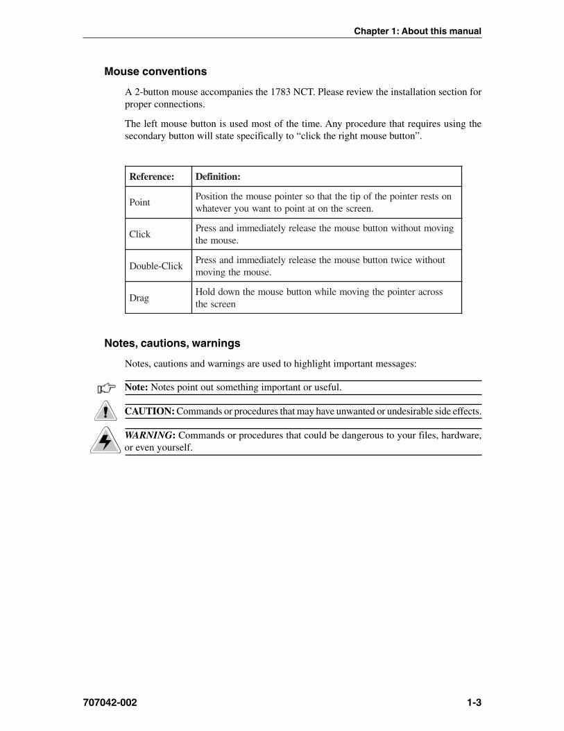
Mouse conventions
A 2-button mouse accompanies the 1783 NCT. Please review the installation section forproper connections.
The left mouse button is used most of the time. Any procedure that requires using thesecondary button will state specifically to “click the right mouse button”.
:ecnerefeR :noitinifeD
tnioPnostserretniopehtfopitehttahtosretniopesuomehtnoitisoP
.neercsehtnotatniopottnawuoyrevetahw
kcilCgnivomtuohtiwnottubesuomehtesaeleryletaidemmidnasserP
.esuomeht
kcilC-elbuoDtuohtiweciwtnottubesuomehtesaeleryletaidemmidnasserP
.esuomehtgnivom
garDssorcaretniopehtgnivomelihwnottubesuomehtnwoddloH
neercseht
Notes, cautions, warnings
Notes, cautions and warnings are used to highlight important messages:
Note: Notes point out something important or useful.
CAUTION: Commands or procedures that may have unwanted or undesirable side effects.
WARNING: Commands or procedures that could be dangerous to your files, hardware,or even yourself.


Chapter 2About the 1783 NCT
In this Chapter...
Overview
Standard features
Personal productivity tools

1783 Network Computing Terminal User’s Manual
2-2 707042-002
Overview
The 1783 NCT is designed to address the requirements of host centric and network centricusers. The 1783 platform supports a real time operating system and a graphical userinterface (GUI). The presence of a micro-kernel, modularized POSIX compliant operatingsystem allows the 1783 to provide power and flexibility not available in server basednetwork terminals. The 1783 supports connectivity over Type A Coax, Ethernet, Twinax,Token Ring, and Serial Ports to IBM hosts, UNIX hosts and Microsoft hosts in a windowingenvironment. This connectivity allows a user simultaneous access to SNA, intranet andInternet networks. Designed with no moving parts, the 1783 NCT is a zero maintenancedevice that allows software installation and updates from a central location.
The 1783 NCT is easy to install, use, manage and support. Maintaining software and dataat a central location eliminates the need to store applications and/or data on a conventionaldesktop workstation. Business applications, corporate intranets and the Internet can allbe accessed from one network terminal.
The 1783 NCT is unique among network computers because of its resident operatingsystem and the caching in flash memory of frequently used applications (such as the1480 Emulator, Telnet, TN3270 and TN5250 host access, the VoyagerTM Web browser,Citrix© ICA Client, and personal productivity tools). This flash memory caching effectivelyeliminates the delay encountered with server-based systems when many users log onsimultaneously.
Standard features
Access to your applications is through a ‘windowing’ environment called a graphical userinterface (GUI). This GUI, Photon micro-GUI, makes it easy to interact with the terminaland enhances flexibility to a variety of tasks.
The following are standard features of the 1783 NCT:
• An Internet browser, called VoyagerTM, that supports HTML 3.2, frames, tables, graphicsand JAVA scripts.
• Telnet Terminal client capability that enables log-in to host systems that are connectedto the Internet.
• A TN3270E client capability that enables accessing 3270 applications on host systemsthat are connected to a LAN/WAN using terminal model type IBM 3279 mod 2,mod 3, mod 4, and mod 5.
• A TN5250 client that enables accessing AS/400 applications.
• Print capability that directs printed material either to a local printer or to a networkprinter.
The following are options of the 1783 NCT:
• A 1480 CUT Emulator (mods 2 - 5) that works with any 1174 compatible control unit.
• A 1490 native Twinax (mods 2 - 5) that work with AS400 systems.
• Token Ring

Chapter 2: About the 1783 NCT
707042-002 2-3
Personal productivity tools
• NCT Mail – A mail handler to use for reading, replying to, forwarding and creatinge-mail (electronic mail).
• Message Pad – A handy way to post a note to yourself.
• Day Minder – An online appointment book.
• Calculator – A convenient on-screen calculator.
• Dialer – A utility that allows the 1783 to be connected to other environments via anexternal modem.
• SnapShot – A resident software utility that allows a displayed image to be printedon your locally attached printer.


Chapter 3Connecting the 1783 NCT
In this Chapter...
Inspecting the package
Setting up the 1783 NCT
Connecting the 1783 NCT
Powering up
Powering down
1783 Network Computing Terminal User’s Manual
707042-0023-2
Inspecting the package
Before unpacking the 1783 NCT, inspect the carton for physical damage. If the exteriorpackage is damaged, contact your local sales office or distributor. Also contact the carrierto request examination of the damage. The carrier is required to complete and sign adamage report form. If the package is not damaged, remove the package contents whichincludes a logic unit, a mouse, an AC power cable, and this user’s guide.
Setting up the 1783 NCT
To set up the 1783 NCT, refer to the diagram on the back of the logic unit and follow thesteps below:
CAUTION: The 1783 NCT has been designed to support the weight of 17-inch or smallerdisplay units. Display units larger than 17 inches MUST be placed beside the logic unit,rather than on top.
1. Place the display unit on top (or beside) of the logic unit and position both withinconnecting distance of an appropriate AC power outlet.
2. Make sure that the Power-On/Off switch is set to O (Off) on both the logic unit andthe display unit.
3. Place the keyboard in front of the logic unit. Pull out the feet underneath the keyboardto adjust it to a higher setting, if desired. Insert the keyboard plug into the keyboardconnector on the back of the logic unit.
4. Refer to the owner’s manual that comes with your display unit for instructions onhow to attach the display unit’s data cable to the logic unit.
5. Plug the display unit’s AC power cable into an appropriate AC power outlet.
6. For the local screen print function, a printer connector is located on the back of thelogic unit. Attach the printer cable (provided with the printer) to the printer connectoron the back of the logic unit.
7. Insert the mouse’s cable connector into the mouse receptacle on the rear of the logicunit. Check to ensure that the connector is firmly seated.
8. Plug one end of the power cable into the AC connector on the back of the logic unit.Plug the other end of the AC power cable into the wall receptacle.

Chapter 3: Connecting the 1783 NCT
707042-002 3-3
1783 NCT - back of logic unit
3
12 4
5 6
78
910 11 12
c d e
ba
1. Fan2. AC Input3. COM 1
4. TV Sound Phone Jacka: S connector (Option)
b: Composite connector(Option)
c: Line Out
d: Line In
e: MIC5. CRT Connector6. COM 2
7. USB (2 ports)8. Expansion Card Area9. Parallel Port
10. RJ 45 Connector
11. PS/2 K/B12. PS/2 Mouse
1. System cooling fan2. Connect to power cord3. 16550UART connect to one serial
device4. Connect to TV & sound port
a. Connect to S-video input of TVb. Connect to NTSC or PAL video
input of TVc. Connect to speaker or audio signal
input of other devicesd. Connect to audio signal output of
other devicese. Connect to microphone
5. Connect CRT monitor6. 16550UART connected to one serial
device7. Connect to USB devices8. The place to plug add-on-card9. Connect to devices with EPP/ECP port
10. Connect to 10/100 base-T Ethernetcable
11. Connect PS/2 type keyboard12. Connect PS/2 type mouse
Term Definition

1783 Network Computing Terminal User’s Manual
707042-0023-4
Connecting the 1783 NCT
Connecting to the SNA network
To connect the 1783 NCT to a coax wiring system, prepare either coax cables or twisted-pair cables according to the following table:
xaoC riaPdetsiwT
htgnelmumixaM )teef0294(sretem0051 )teef009(sretem772
Coax cable and twisted-pair cables can be combined. The following formula shows lengths:
(coax length) + (5 x twisted-pair length) < 1370 meters (4500 feet)
1. Locate the coax or twisted-pair SNA network cable.
2. Align the end of the SNA network cable with the Coax connector on the back of thelogic unit.
3. Connect the cable and secure it in place by turning the retaining ring clockwise untilit is tight.
Connecting to an Ethernet LAN
To connect the 1783 NCT to an Ethernet LAN, prepare the Category 5 or unshieldedtwisted-pair cables according to the following table:
1. Locate the Category 5 UTP Local Area Network (LAN) cable.
5ro,4,3yrogetaC dradnatSEEEI/ISNA
htgneLmumixaM )teef480.823(sretem001retaergro41noitceS0991-I3.208
htgneLmuminiM )teef182.3(retem0.1
2. Plug the LAN cable into the RJ45 connector on the back of the logic unit.
Connecting a modem to the Serial Port1. Connect the external modem’s 9-pin connector into the serial port located on the rear
panel of the logic unit.
2. Secure the cable’s fastening screws to ensure proper connection.

Chapter 3: Connecting the 1783 NCT
707042-002 3-5
Connecting to the 5250 Network
Connect the display station to the host system or to a controller by following these stepswith cable lengths as indicated:
epyTelbaC tnelaviuqero,7029nodleB,8189ahplA
htgneLmumixaM sretem0051
1. Locate the twinax cable extending from the host system or from the closest device onthe host system side of the line. Attach the connector at the end of this cable to eithersocket on the two-socket end of the T-connector cable.
2. Push the connector into the socket and turn the retaining ring clockwise until tight.
3. Align the 9-pin Sub-D connector end of the T-connector cable with the twinaxconnector on the back of the logic element. Connect the cable to the logic elementand secure it in place by turning the retaining screws until tight.
4. If there are other terminals in the daisy chain, connect the second cable from the nextterminal to the unused socket of the two-socket end of the T-connector cable beforeattaching the T-connector cable to the back of the logic element.
5. Make sure the twinax line is terminated properly. The last T-connector should haveone input open. If the last device is a Visara device, it must has a T-connector. If thelast device is not a Visara device, ensure that it is terminated correctly according tothe manufacturer’s instructions.
Note: When one connector of the two-socket end of twinax cable is unattached, the cableis self-terminating. When the single end of the connector cable is unattached, the cable isin Pass Through mode, and signals continue on to the next connected device. Never attachthe twinax cable directly to the logic element.
Powering up
After the 1783 NCT has been properly installed and connected, it is ready to operateonline. To ensure that the 1783 NCT is prepared for operating, perform the followingprocedure. If you encounter operational difficulty or if the unit malfunctions, contactyour system administrator.
1. Set the Power-On/Off switch to On ( | ) to turn on power.
2. If the Power-On indicator does not light, check the power and make sure the unit iscompletely plugged in. If the mouse pointer does not appear, or the Taskbar does notappear, check to see if connecting cables are securely connected to the back of thelogic unit.
3. A beep indicates that the terminal is connected properly. If you hear more than onebeep, check the table on the following page for actions to take.

1783 Network Computing Terminal User’s Manual
707042-0023-6
rebmuNspeebfo noitaruD noitpircseD noitcAyrevoceR
2 gnol1trohs1 rorredraobyeK ,stsisrepmelborpfI.noitcennocdraobyekkcehC
.rotartsinimdametsysruoytcatnoc
2 trohs2 rorreTSOPelbarevoceR ,stsisrepmelborpfI.noitcennocdraobyekkcehC.rotartsinimdametsysruoytcatnoc
3 trohs3 rorreTSOPelbarevocer-noN .rotartsinimdametsysruoytcatnoC
3 gnol1trohs2
nacsMOR,evitcasiyalpsidfIyromemreppunirorre .rotartsinimdametsysruoytcatnoC
3 gnol1trohs2
,evitcatonsiyalpsidfIrorreyalpsid
fI.noitcennocdrocrewopdnatinuyalpsidkcehC.rotartsinimdametsysruoytcatnoc,stsisrepmelborp
3 gnol2trohs1 rorrenoitazilaitinixaoC tcatnoc,stsisrepmelborpfI.noitcennocxaockcehC
.rotartsinimdametsysruoy
4 gnol2trohs2 rorrenoitazilaitinixaoC/PI tcatnoc,stsisrepmelborpfI.noitcennocxaockcehC
.rotartsinimdametsysruoy
4 gnol3trohs1 rorreyalrevoyromemxaoC ,stsisrepmelborpfI.nokcabdnaffotinuehtrewoP
.rotartsinimdametsysruoytcatnoc
5 gnol2trohs3
noitazilaitinirevird-xaoC/PIrorre
tcatnoc,stsisrepmelborpfI.noitcennocxaockcehC.rotartsinimdametsysruoy
5 gnol3trohs2
3871ehtgniniatbororrEnoitarugifnockrowten
,stsisrepmelborpfI.nokcabdnaffotinuehtrewoP.3871ehterugifnocerrotartsinimdametsysehtevah
6 gnol2trohs4 rorrenoitazilaitinitenrehtE
ehtrewopnehtdnanoitcennoctenrehtEehtkcehCtcatnoc,stsisrepmelborpfI.nokcabdnaffotinu
.rotartsinimdametsysruoy
6 gnol3trohs3
sserddaPInagniniatbororrElocotorpPtoobehtgnisu
tcatnoc,stsisrepmelborpfI.revresPtoobehtkcehC.rotartsinimdametsysruoy
7 gnol2trohs5 srevirdPCHDgnidaolrorrE .nokcabdnaffotinuehtrewoP
7 gnol3trohs4
tsohgniniatbororrEnoitamrofninoitarugifnoc
tcennoc
,stsisrepmelborpfI.nokcabdnaffotinuehtrewoP.3871ehterugifnocerrotartsinimdametsysehtevah
4. Adjust the brightness control, the contrast control, vertical centering, and the horizontalcentering control, if necessary.
Powering down1. Save all work in process and close any open applications.
2. Move the Power On/Off switch to Off (O).
The next chapter describes how to define characteristics and preferences for the displayunit and printer so that you may begin to use the Network Computing Terminal.

Chapter 4Using Windows
In this Chapter...
Using the 1783 NCT
What should I do first?
How to start the 1783
Using the mouse
Pointers
Anatomy of a window
Using the Window Menu
Using the Taskbar
Keyboard shortcuts
1783 Network Computing Terminal User’s Manual
707042-0024-2
Using the 1783 NCT
This section introduces the new operating environment of the 1783 Network ComputingTerminal (NCT). It explains how to do most tasks and provides tips for getting the mostout of the NCT.
If you have used windowing systems before, the “look and feel” will seem quite natural.If not, the intuitive interface is easy to learn and use.
What should I do first?
First, read through the next section - all the basics about using the mouse and workingwith windows are explained, and some handy keyboard shortcuts are included. Afterreading this section, familiarize yourself with the display’s workspace. Try starting anapplication from the start menu - the Day Minder is a good place to start.
How to start the 1783
The system has been set up to start automatically at power-up. Your user ID and/or passwordmay be required in the 1783 NCT login dialog box.
A typical workspace
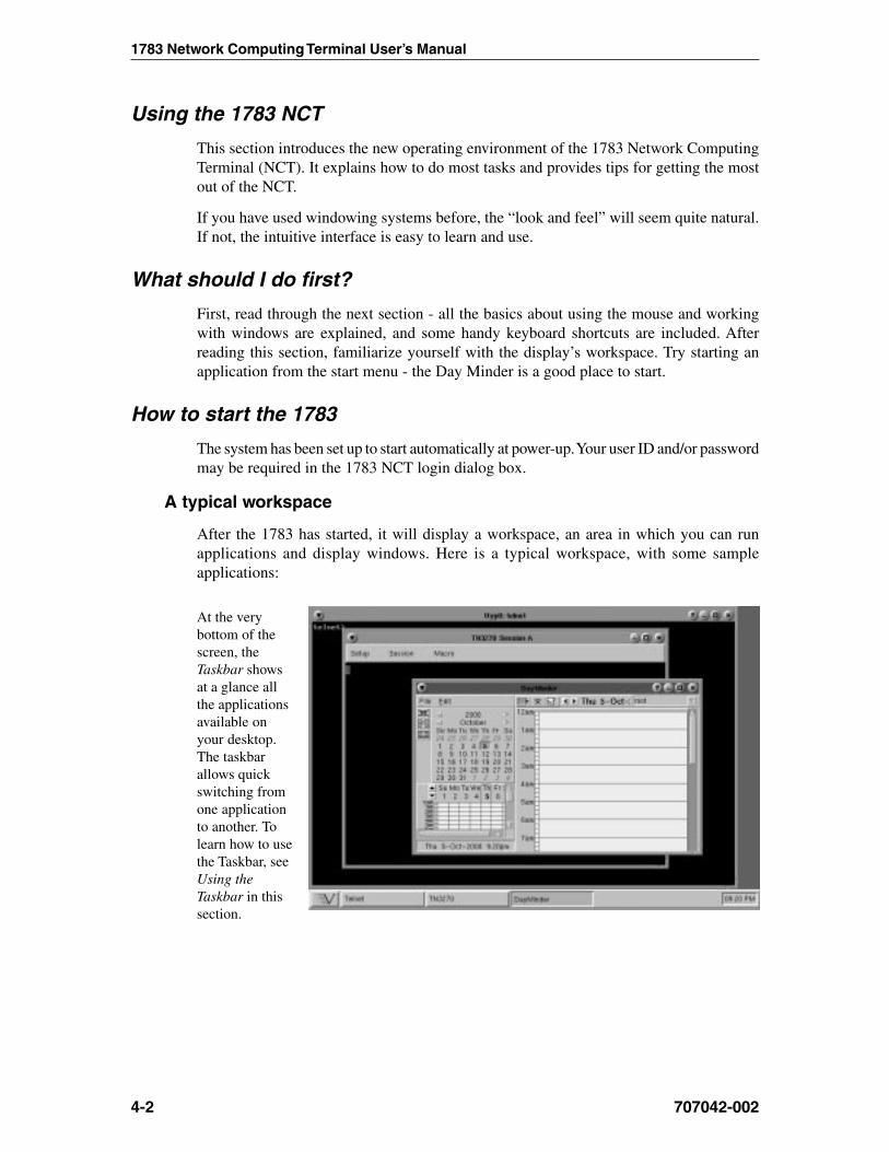
After the 1783 has started, it will display a workspace, an area in which you can runapplications and display windows. Here is a typical workspace, with some sampleapplications:
At the verybottom of thescreen, theTaskbar showsat a glance allthe applicationsavailable onyour desktop.The taskbarallows quickswitching fromone applicationto another. Tolearn how to usethe Taskbar, seeUsing theTaskbar in thissection.

Chapter 4: Using Windows
707042-002 4-3
Using the mouse
Two common mouse operations are:
• Clicking – Pressing and releasing a mouse button.
• Dragging – Holding down a mouse button, moving the mouse, and then releasing thebutton.
Note: When the word “click” or “drag” is used in this documentation, and no mousebutton is specified, use the LEFT mouse button. When the right button should be usedyou will be explicitly instructed to do so.
Use the right mouse button to bring up a context-sensitive menu in most applications.
Pointers
As the mouse is moved, the pointer sometimes changes to provide feedback. Here are thepointers most often seen:
Basic pointer - point to objects to be selectedor to indicate where the cursor should bepositioned.
Busy pointer - Indicates that an operation isin process and must finish before data entrycan be resumed.
Resize pointer - appears when the pointerpasses over a window frame; the two arrowsindicate the direction the window can beresized.
Move pointer - appears when the pointerpasses over a window title bar; simply holddown the mouse button and drag the windowto a new location.
I-beam pointer - appears in text-entry fieldsto indicate that the application is ready toaccept keyboard input.
No-input pointer - Indicates the window isnot accepting input.
1783 Network Computing Terminal User’s Manual
707042-0024-4
Anatomy of a window
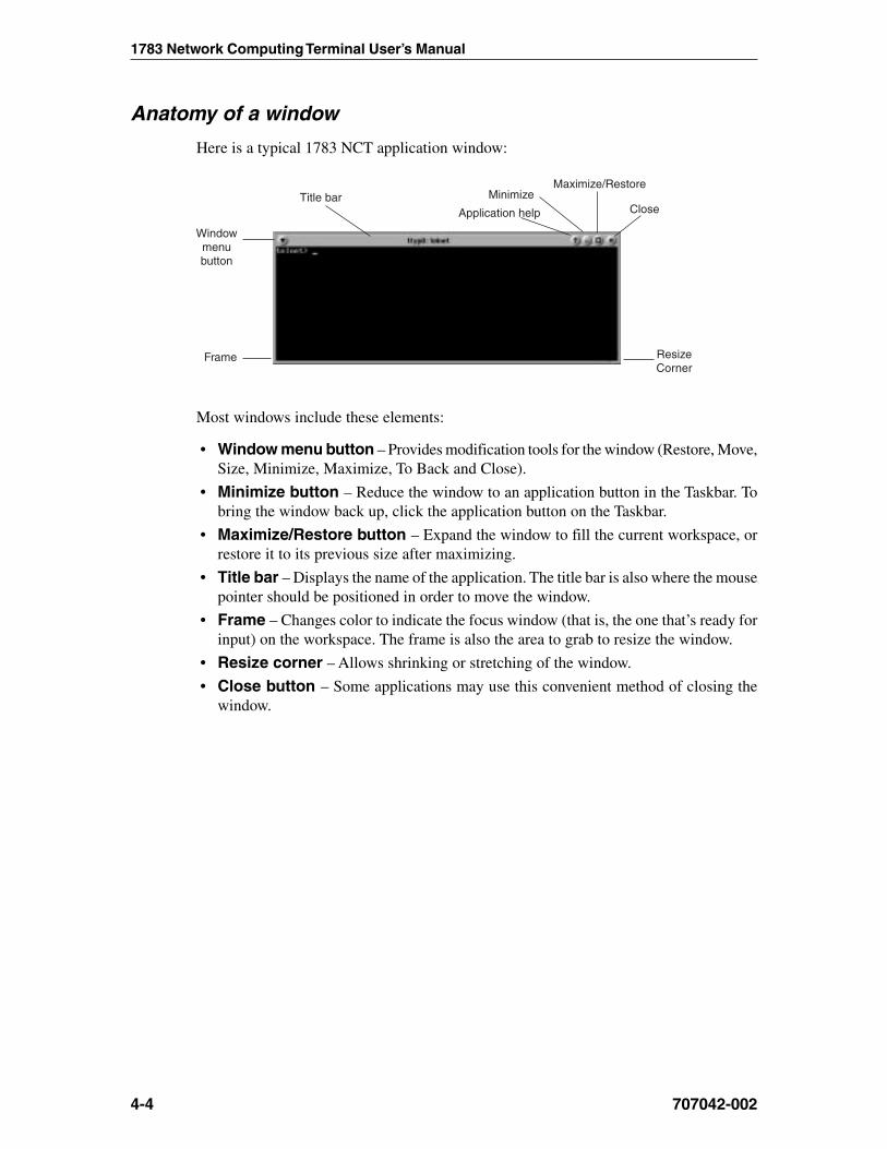
Here is a typical 1783 NCT application window:
Title bar Minimize
Application help
Maximize/Restore
Close
Windowmenubutton
Frame ResizeCorner
Most windows include these elements:
• Window menu button – Provides modification tools for the window (Restore, Move,Size, Minimize, Maximize, To Back and Close).
• Minimize button – Reduce the window to an application button in the Taskbar. Tobring the window back up, click the application button on the Taskbar.
• Maximize/Restore button – Expand the window to fill the current workspace, orrestore it to its previous size after maximizing.
• Title bar – Displays the name of the application. The title bar is also where the mousepointer should be positioned in order to move the window.
• Frame – Changes color to indicate the focus window (that is, the one that’s ready forinput) on the workspace. The frame is also the area to grab to resize the window.
• Resize corner – Allows shrinking or stretching of the window.
• Close button – Some applications may use this convenient method of closing thewindow.

Chapter 4: Using Windows
707042-002 4-5
Using the Window Menu
To open an application’s Window menu, click on the Window menu button in the window’supper left corner.
The Window menu allows you to:
• Restore the window’s size (after maximizing or minimizing it).• Move the window – the window will track the mouse pointer until the mouse button
is clicked.• Size the window – as the pointer is moved outside the frame, an outline will track it
until the mouse button is clicked.• Minimize the window – reduces the window to an application button in the Taskbar.
To bring the window back up, just click on the button in the Taskbar.• Maximize the window – expands the window to fill the current workspace.• To Back – pushes the window behind any other windows that are open on the
workspace.• Close – closes the application. An application can also be closed by double-clicking
on the menu button.
CAUTION: Selecting the Close item may immediately terminate the application runningin that window without prompting you to confirm. Always remember to save your workbefore you click on Close!
Note: Some tabs or tool bar icons may be subdued or “grayed out”; these tasks are notaccessible at this time.
Using the Taskbar
The Taskbar provides a quick and easy way to switch from one application to another andto restore applications to their normal size on the workspace.
The Taskbar includes the following:• Application list button - displays a menu of applications made available for
your use by your system administrator.• A label button for each application that is running. The label will appear whether the
application is visible on the screen or in the minimized mode.
To start-up an available application:
1. Click the button. The menu of applications will appear.
2. Select the application you wish to work with.
To switch to any running application, click on the application’s button on the Taskbar.The application’s window will be restored if minimized, brought to the front, and willbecome the focus window.
Note: The system administrator may have configured your 1783 NCT to automaticallystart an application in full screen mode when the 1783 NCT is powered on. The application’ssection in this document will describe how to access the taskbar from a full screen.

1783 Network Computing Terminal User’s Manual
707042-0024-6
Keyboard shortcuts
The following tables summarize the keyboard shortcuts that may be used.
Workspace operations
:ottnawuoyfI :sserP
kcatswodniwehtfotnorfehtotwodniwkcabehtevoM csE-tlA-lrtC
kcatswodniwehtfokcabehtotwodniwtnorfehtevoM csE-tfihS-tlA-lrtC
;tsrifemanehtgniwohs,snoitacilppanepohguorhtelcyCtlAesaeler,tnorfehtotnoitacilppadeyalpsidagnirbot
baT-tlA-lrtC
ottnorfgnivomtub,snoitacilppanepohguorhtelcyCkcab
baT-tfihS-tlA-lrtC
Window operations
All of these commands affect the focus window:
:ottnawuoyfI :sserP
tnorfehtotwodniwehtevoM 2F-tlA-lrtC
kcabehtotwodniwehtevoM 3F-tlA-lrtC
wodniwehtesolC 4F-tlA-lrtC
neebsahtifiezissuoiverpstiotwodniwehterotseRdezimixam
5F-tlA-lrtC
wodniwehtevoM 7F-tlA-lrtC
wodniwehtezimixaM 01F-tlA-lrtC
unemwodniwehtyalpsiD ecapS-tlA-lrtC
unemwodniwehtesolC csE

Chapter 5Using Print Services
In this Chapter...
Printer setup
Installing a printer
Changing the default printer
Printing when a printer has not been set up
Printer properties
Print preview
LPR/LPD print feature
Configuring remote printers
Using the 1783 as an LPR server

1783 Network Computing Terminal User’s Manual
707042-0025-2
This chapter shows you how to install and select printers, and how to preview documentsbefore printing.
Printer setup
The first step in being able to print files is to select a printer from the Printer Setup dialog.
1. Click the button (located at the lower left-hand corner of the screen).
2. Click Printers. The Photon Printer Setup panel will appear:
Note: Contact your system administrator if there are no printers listed in the AvailablePrinters panel.
The options of the printer setup dialog are:
• Installed Printers – Displays the list and location of printers that are installed.
Note: Local means there is a parallel printer attached to this unit. For remote locationprinters to print, they must be configured using the Remote Printers application. (SeeConfiguring Remote Printers, page 5-7.)
• Available Printers – Displays the lists and location of printers that may be installed.Output that goes to spool devices is indicated with a printer icon.
• Install – Installs the printer that is selected in the list of Available Printers.
• Uninstall – Uninstalls the printer that is selected in the list of Installed Printers.
• Set Default Printer – Sets the default printer to the one selected in the InstalledPrinters panel.
• Properties – Specify printer options such as paper size, margins, and print qualityfor the printer selected in the Installed Printers panel.
• Save – Saves the current configuration.
• Exit – Closes the printer setup window.

Chapter 5: Using print services
707042-002 5-3
Installing a printer
As many printers as necessary may be installed using the following steps:
1. Click on a printer name from the list of Available Printers in the right panel. Theprinter name and location will become highlighted, and the Install button will bemade available for use.
2. Click Install. The selected printer moves to the Installed Printers panel on the left.
Changing the default printer
To change the default printer:
1. Click the printer name that should be selected as the default from the list of InstalledPrinters. If it is the only printer selected, the Set Default Printer button will bemade available for use.
2. Click Set Default Printer. The printer which was selected will move to the top ofthe list. The Set Default Printer Button changes to Is Default Printer.
When printing from an application, the printer chosen as default is displayed in the Printerfield. Before printing, you can accept the default printer, or choose from any of the printersin the dropdown printer list.
Printing when a printer has not been set up
If a printer was not installed prior to selecting the Print command from an application’smenu, you will be prompted to install a printer. The Select Printer panel will appear:
Click the Add Printer... button – the Photon Printer Setup panel will open. Install theprinter(s) by following the steps outlined in Installing a Printer.
1783 Network Computing Terminal User’s Manual
707042-0025-4
Printer properties
Printer properties can be assigned for either text printing or graphical images. The propertiesfor the selected printer may be viewed by clicking the Properties button in the PrinterSetup panel (shown on page 5-2).
There are five tabs that display property information:
• Paper tab• Graphics tab• Margins tab• Other tab• Info tab
Note: The values displayed on your screen for the tab options may differ from theillustrations in this guide. Refer to your printer’s documentation for the values that defineyour printer’s capabilities, or contact your system administrator.
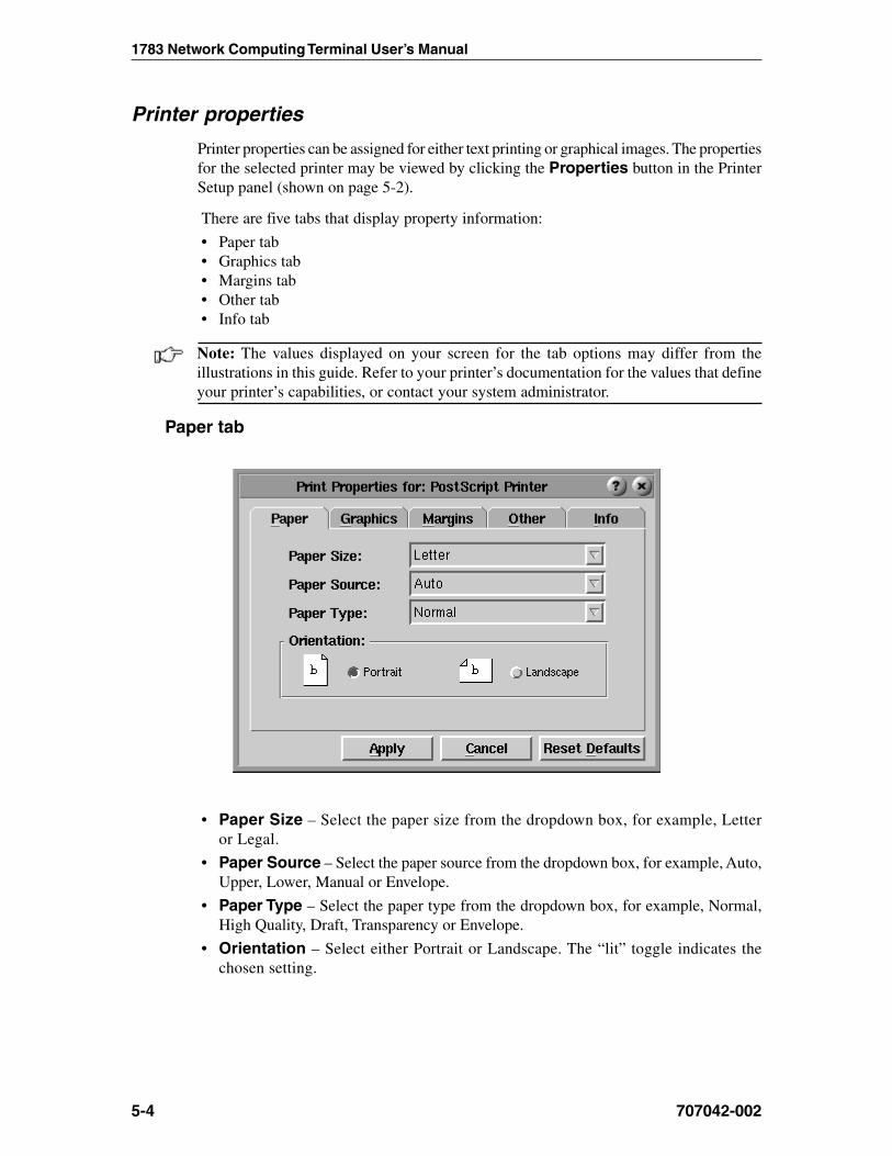
Paper tab
• Paper Size – Select the paper size from the dropdown box, for example, Letteror Legal.
• Paper Source – Select the paper source from the dropdown box, for example, Auto,Upper, Lower, Manual or Envelope.
• Paper Type – Select the paper type from the dropdown box, for example, Normal,High Quality, Draft, Transparency or Envelope.
• Orientation – Select either Portrait or Landscape. The “lit” toggle indicates thechosen setting.
Chapter 5: Using print services
707042-002 5-5
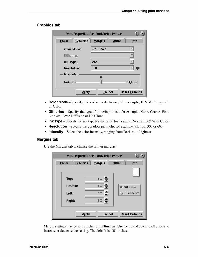
Graphics tab
• Color Mode – Specify the color mode to use, for example, B & W, Greyscaleor Color.
• Dithering – Specify the type of dithering to use, for example, None, Coarse, Fine,Line Art, Error Diffusion or Half Tone.
• Ink Type – Specify the ink type for the print, for example, Normal, B & W or Color.
• Resolution – Specify the dpi (dots per inch), for example, 75, 150, 300 or 600.
• Intensity – Select the color intensity, ranging from Darkest to Lightest.
Margins tab
Use the Margins tab to change the printer margins:
Margin settings may be set in inches or millimeters. Use the up and down scroll arrows toincrease or decrease the setting. The default is .001 inches.

1783 Network Computing Terminal User’s Manual
707042-0025-6
Other tab
Use this tab dialog to specify single or double-sided printing and the collating mode.
• Duplex – Specifies 1- or 2-sided printing.
• Collating Mode – Select [1,1,1] or [1,2,3] or neither.
Info tab
The Info tab shows the selected printer’s name, location, spool device, and spoolfilter information.
When the printer properties configuration is complete, click Apply to save the new settings,or click Reset Defaults to return to the defaults set by the manufacturer.
Print preview
Click Preview from the Select Printer panel to preview on-screen how a document willlook when printed.
In print preview you can:
• Scroll forwards and backwards through your document, if it is larger than one page,by using the Next Page and Previous Page arrows.
• Zoom closer into or further away from the image by selecting a percentage from theMagnification dropdown box.
• Print the document by opening the File menu (in the upper left-hand corner of thescreen) and clicking Print.
Chapter 5: Using print services
707042-002 5-7
LPR/LPD print feature
LPR (Line Print Remote)/LPD (Line Print Daemon) is a print server protocol widelyused on the internet for communicating between clients and servers. An LPR-enableddevice (the 1783, for instance) requests a LPD-enabled device (usually a printer orprint server) to print a specific print job. The 1783 can act as an LPR-enabled deviceand/or an LPD-enabled device. Following are descriptions of how to configure the 1783for LPR/LPD.
Remote Printing must be configured to enable LPR printing for the following 1783applications:
• VT220 • 1480 Emulation
• TN3270E • 1490 Emulation
• TN5250 • Voyager Web Browser
The 1783 supports a total of nine remote printers. Three of these printers are static-definedand cannot be deleted. The remaining six are user-defined. The three static-defined printersare:
• lan_hp
• lan_ps
• lan_epson
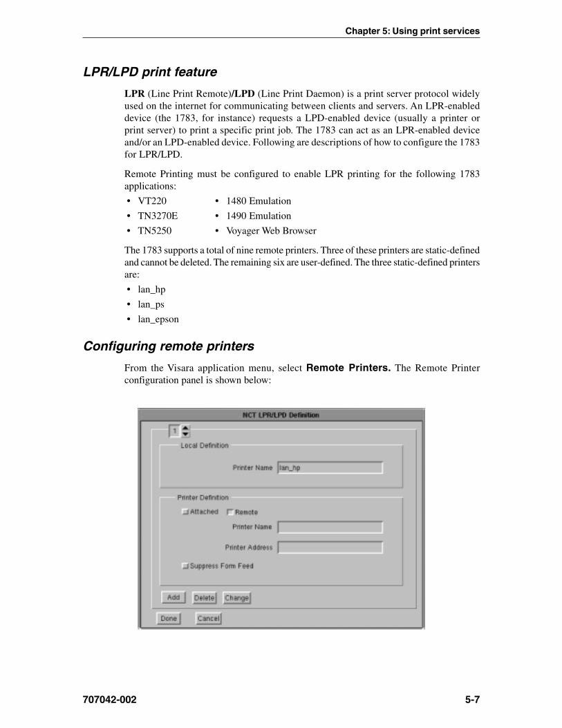
Configuring remote printers
From the Visara application menu, select Remote Printers. The Remote Printerconfiguration panel is shown below:

1783 Network Computing Terminal User’s Manual
707042-0025-8
• Remote Printer Selection – Use the up or down arrows to select a printer (1-9)
• Local Definition Printer Name – User-defined field. This name should be adescriptive name for the remote printer. Note that the first three printers are static-defined and the Local Definition printer name may not be changed. The remaining sixare user-defined.
Remote Printer Definition• Attached – the printer is attached to the parallel port on the 1783.
• Remote – the printer is remotely attached on the LAN.
• Printer Name – Queue name that print jobs are sent to from an LPR-enabled device(if required).
• IP Address – The IP address of the remote printer. If the printer is locally attached,/dev/par1 is displayed in this field indicating that the printer is attached to the parallelport. Do not change this entry if the printer is locally defined. Otherwise, enter theunique IP address of the remote printer.
• Add – Add a new remote printer definition. To add a new remote printer, simply selectan existing printer, make the desired changes, and click Add.
• Delete – Delete an existing remote printer definition.
• Change – Change an existing remote printer definition.
• Done – Save changes and exit.
• Cancel – Discard changes and exit.
Using the 1783 as an LPR server
The 1783 can be configured to act as an LPR server for other 1783’s on the network. Toconfigure the 1783 as an LPR server:
From the 1783 with the printer attached locally:
Add a new printer definition to Remote Printers. Do this by selecting an existing definitionand making the following changes:
1. Select a Local Definition name, such as lpr_server.
2. Select the Attached button.
3. Select Add. A new printer definition will be created.
From other 1783’s on the network:
Add a new printer definition to Remote Printers. Do this by selecting an existing definitionand making the following changes:
1. Select a Local Definition Printer Name, such as 1783_rem_prtr.
2. In the Printer Definition Printer Name field, enter the local definition name that wasdefined above, such as lpr_server.
3. In the Printer Definition IP Address field, enter the IP address of the 1783 with thelocally attached printer.
Note: The 1783 must be restarted when changes are made to Remote Printer configurationfor the changes to become effective.
Chapter 61480 CUT Emulator
In this Chapter...
Standard features
Accessing your application program
Moving the cursor
Entering and editing data
Selecting data fields
Sending data
Monitoring response time
Configuring the 1480 CUT Emulator
1480 miscellaneous
Printer setup and printing
Dual Screen feature
Configuring Dual Screen mode
Starting Dual Screen mode
Dual Screen mode enhancements

1783 Network Computing Terminal User’s Manual
6-2 707042-002
The 1480 CUT Emulator is a 1480 Enhanced Function Display Emulator that offers awide range of functions and applications for the traditional IBM 3270 terminal user.
The 1480 CUT Emulator can be used with a color monitor or a VGA monochrome monitor.For remote printing, a coax printer can be attached via the Visara controller, or hard copyof all data on the screen can be printed on an optional local screen printer or on a remoteLAN printer.
Standard features
The 1480 CUT Emulator provides the following standard features:
Display screen features• Window Menus – The window menus offer simplicity and ease of use for all setup
functions.
• Switchable Screen Formats – The 1480 CUT Emulator supports four (4) screensizes that can be selected from setup menus. The controller to which the 1480 CUTEmulator attaches must support the screen size used. Check with your systemadministrator.
Data entry features• Mono/DualCase Mode – Allows characters to be displayed as all uppercase
characters or as upper- and lowercase characters.
• Mark Unprotected Field Indicator – The 1480 CUT Emulator can be requestedto mark unprotected fields with a special character.
• Row/Column – Displays the current cursor location on the operator status row.• Numeric Lock – Allows a field to be defined to accept only numeric characters, plus
the Period, Minus, and Dup keys. The comma may be substituted for the period onsome international keyboard - controller functions.

Chapter 6: 1480 CUT emulator
707042-002 6-3
• Audible Alarm – Sounds when a character is entered in the next-to-last characterposition of the screen (if the last character position is unprotected) or when the hostsystem signals the terminal.
• Entry Assist Function – Facilitates the creation and editing of text such as memos,letters, and documents. The attached controller must support this function.
Printing features• Local Screen Print – Allows a hard copy of displayed text to be made using the
screen print function. Print quality, line density, and print pitch can be specified.
• Coax Printing – Allows printing to be directed to various printers on your networkor controller.
Other features• Response Time Monitor – Supports host-controlled transaction response time
monitoring. This feature helps your organization’s systems staff to analyze and improvethe rate at which your terminal responds to your actions. The controller must be properlyconfigured to support this feature.
• Modifiable Keyboard – Using the Keyboard Definition mode, the keyboard layoutcan be modified by interchanging and adding keycaps. The controller must be properlyconfigured to support this feature.
• Mouse-Pen – Using the right mouse button, light-pen detectable fields can be activatedin the 1480 emulation applications.
• Light-Pen – Light-pen detectable fields can be activated in the 1480 emulationapplications.
Accessing your application program
To start the 1480 CUT Emulator:
1. Click the button in the lower left-hand corner of the screen. The applicationmenu will appear.
2. Click 1480 Emulation from the application menu.
3. Call up an application by one of the following methods:• Using the Attention, PA, F or PF, Clear, or Enter key,• Select from your system’s menu of applications.
Contact your supervisor or system administrator for specific information on how to accessyour application(s).
The application program can guide your data entry process by:
• limiting numeric fields to digits, period, DUP and minus
• intensifying fields where you can enter data
• covering confidential information so it does not appear on your screen.
Note: To enter nonnumeric, uppercase characters in numeric fields, press Shift.
1783 Network Computing Terminal User’s Manual
6-4 707042-002
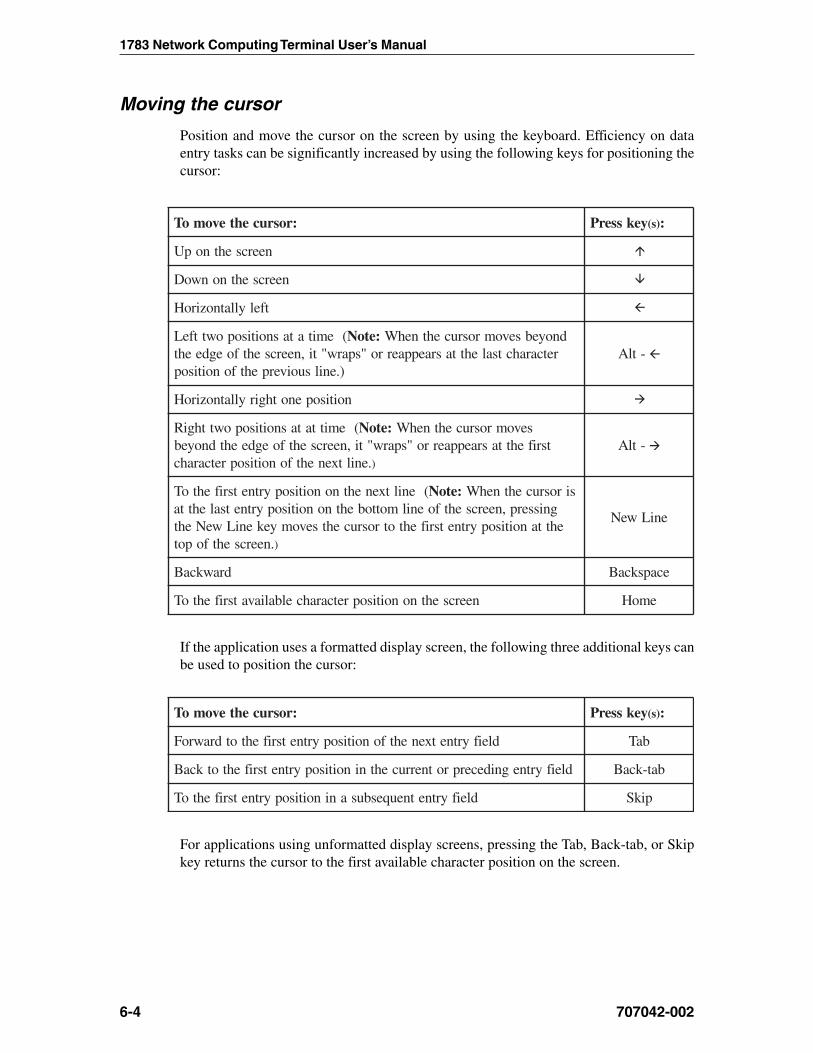
Moving the cursor
Position and move the cursor on the screen by using the keyboard. Efficiency on dataentry tasks can be significantly increased by using the following keys for positioning thecursor:
:rosrucehtevomoT yeksserP )s( :
neercsehtnopU
neercsehtnonwoD
tfelyllatnoziroH
(emitatasnoitisopowttfeL :etoN dnoyebsevomrosrucehtnehWretcarahctsalehttasraeppaerro"sparw"ti,neercsehtfoegdeeht
).enilsuoiverpehtfonoitisop-tlA
noitisopenothgiryllatnoziroH
(emittatasnoitisopowtthgiR :etoN sevomrosrucehtnehWtsrifehttasraeppaerro"sparw"ti,neercsehtfoegdeehtdnoyeb
.eniltxenehtfonoitisopretcarahc )
-tlA
(eniltxenehtnonoitisopyrtnetsrifehtoT :etoN sirosrucehtnehWgnisserp,neercsehtfoenilmottobehtnonoitisopyrtnetsalehttaehttanoitisopyrtnetsrifehtotrosrucehtsevomyekeniLweNeht
.neercsehtfopot )
eniLweN
drawkcaB ecapskcaB
neercsehtnonoitisopretcarahcelbaliavatsrifehtoT emoH
If the application uses a formatted display screen, the following three additional keys canbe used to position the cursor:
:rosrucehtevomoT yeksserP )s( :
dleifyrtnetxenehtfonoitisopyrtnetsrifehtotdrawroF baT
dleifyrtnegnidecerprotnerrucehtninoitisopyrtnetsrifehtotkcaB bat-kcaB
dleifyrtnetneuqesbusaninoitisopyrtnetsrifehtoT pikS
For applications using unformatted display screens, pressing the Tab, Back-tab, or Skipkey returns the cursor to the first available character position on the screen.

Chapter 6: 1480 CUT emulator
707042-002 6-5
Entering and editing data
All the keys described in Moving the Cursor can be used to enter and edit data input. Inaddition, the following keys can be used to add or delete information:
:noitcnufsihtmrofrepoT yeksserP )s( :
tnerrucs'rosrucehttasretcarahcgniddarofedomtresnIretnEnoitisop
tresnI
edomtresnItixE teseR
noitisoptnerrucs'rosrucehttaretcarahcaevomeR eteleD
noitisoprosructnerrucehttagninnigebdrowaeteleD( :etoN hcihwottinulortnocehtfiylnolanoitcnufsidroWeteleD
).erutaeftsissAyrtnEehtstroppusdehcattasinoitatsyalpsidehtdroWeteleD
otnoitisoptnerrucs'rosrucehtmorfsnoitisopdleifyrtnellaesarEdleiffodneeht
FOErE
tsrifehtotrosrucehtevomdnasnoitisopdleifyrtnellaesarEnoitisopretcarahcelbaliava
pnIrE
noitisopyrtnetsrifehtotrosrucehtevomdnaatadderetnetaepeRdleifyrtnetneuqesbusehtfo
puD-tfihS
dleiftupninafodneehtskramtahtretcarahcaretnE kraMdleiF-tfihS
Note: Shift to uppercase characters by using Numeric mode, as well as pressing Shift.Press either Shift or Shift Lock to reverse Shift Lock.
Selecting data fields
The application program may be designed to present to you certain fields that can beselected for further processing by the application program. These fields are markedwith a “?”.
To select a field, perform one of the following actions:
• Press the CrSel key
• Move the cursor to cover any character in the field or to cover the “?” and click theright mouse button.
“ > ” replaces the “?” associated with the field you select. If you accidentally select thewrong field, press the CrSel key or right mouse button to deselect it.

1783 Network Computing Terminal User’s Manual
6-6 707042-002
To send the field(s) to the application program for processing, do one of the following,depending on how the application program was designed:
• Press the Enter key.• Press the CrSel key after positioning the cursor on an attention field. (Attention
fields are marked with &’s and spaces.)• Position the mouse cursor to point to the desired attention field and click the
right mouse button.
Sending data
To send the displayed data to the host application before continuing to enter data:
1. Check to be sure that all fields required by the application have been filled.
Note: When a data character is entered in the next-to-last character position on the screen,the audible alarm sounds to remind you that the cursor is near the end of the screen. Ifdata entry continues, the cursor “wraps”’ and reappears in the first available characterposition of the screen. Subsequently entered characters replace displayed characters,resulting in loss of previous entries.
2. Press the Enter key to send the displayed data to the host application.
3. Press the Clear key. This has the following effect:• Erases all displayed data on the screen• Returns the cursor to the first available character position• Signals the host application that a “clear” operation has occurred.
System Request variations
Depending on the online rules condition symbol that is displayed on the operator statusrow, you will be able to send system request messages. Press Alt - Sys Rq, for theseresults:
Operator StatusRow Display: Result:
A Sends a message that your unit may be malfunctioning orthat a test request message is on the screen.
B Clears the display and switches the display station betweenthe control (or master) program and application programs.
Contact your supervisor for additional information about this key combination.
Program Access (PA) function
The application program in use determines specific functions of the Program Access(PA) key. Contact your supervisor for further information.
Function (F or PF) keys
The application program in use determines specific functions of the Function (F or PF)keys. Contact your supervisor for further information.
Chapter 6: 1480 CUT emulator
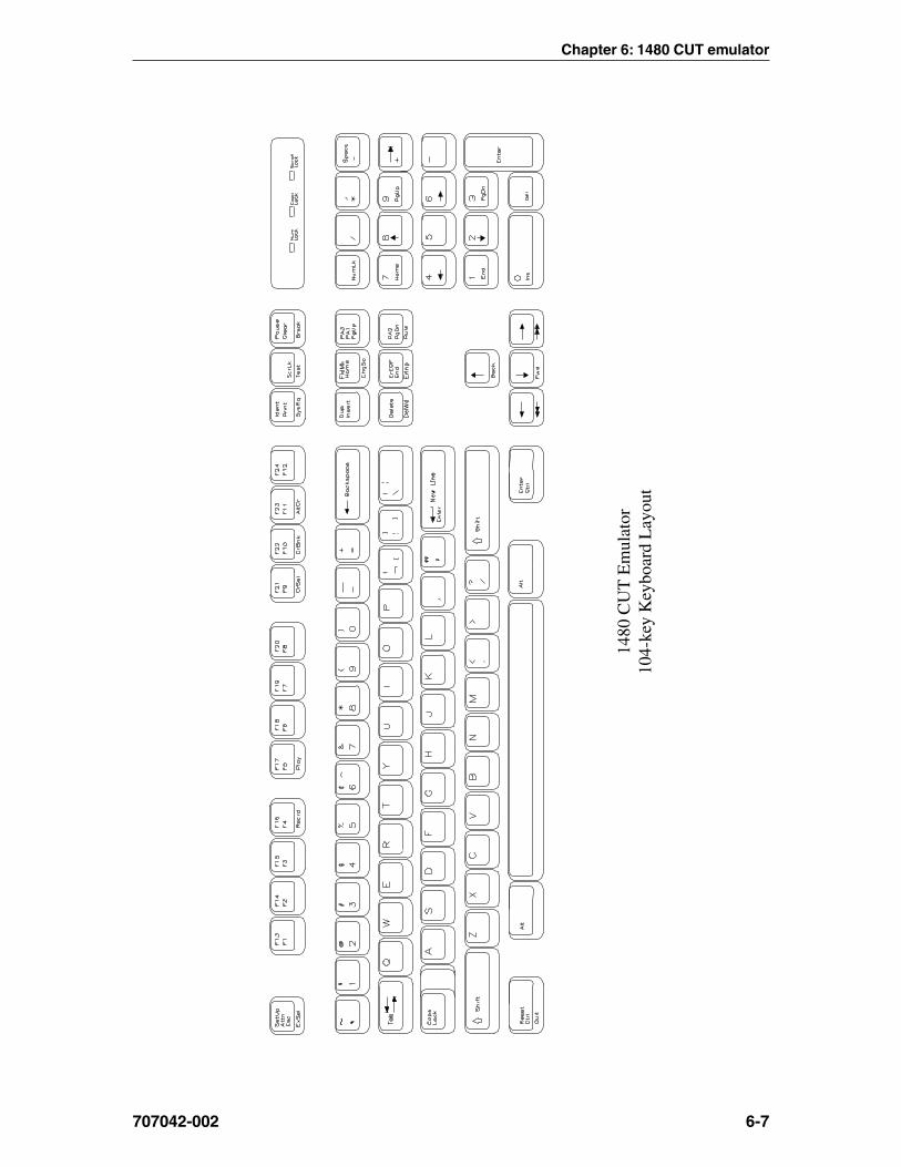
707042-002 6-7
1480
CU
T E
mul
ator
104-
key
Key
boar
d L
ayou
t

1783 Network Computing Terminal User’s Manual
6-8 707042-002
1480
CU
T E
mul
ator
122-
key
Key
boar
d L
ayou
t
Chapter 6: 1480 CUT emulator
707042-002 6-9
Monitoring response time
At times you may be requested to assist in monitoring and analyzing the speed of systemresponse at your terminal, or you may wish to collect this data on your own.
Note: The attached controller must support this function.
To start the Response Time Monitor:
1. Press the ExSel key
2. Press the F19 key.
To stop the Response Time Monitor, repeat the sequence above.
Configuring the 1480 CUT Emulator
The configuration function enables the environment to be set up to suit your needs andwork habits while working in CUT emulation mode.
Defining and selecting features
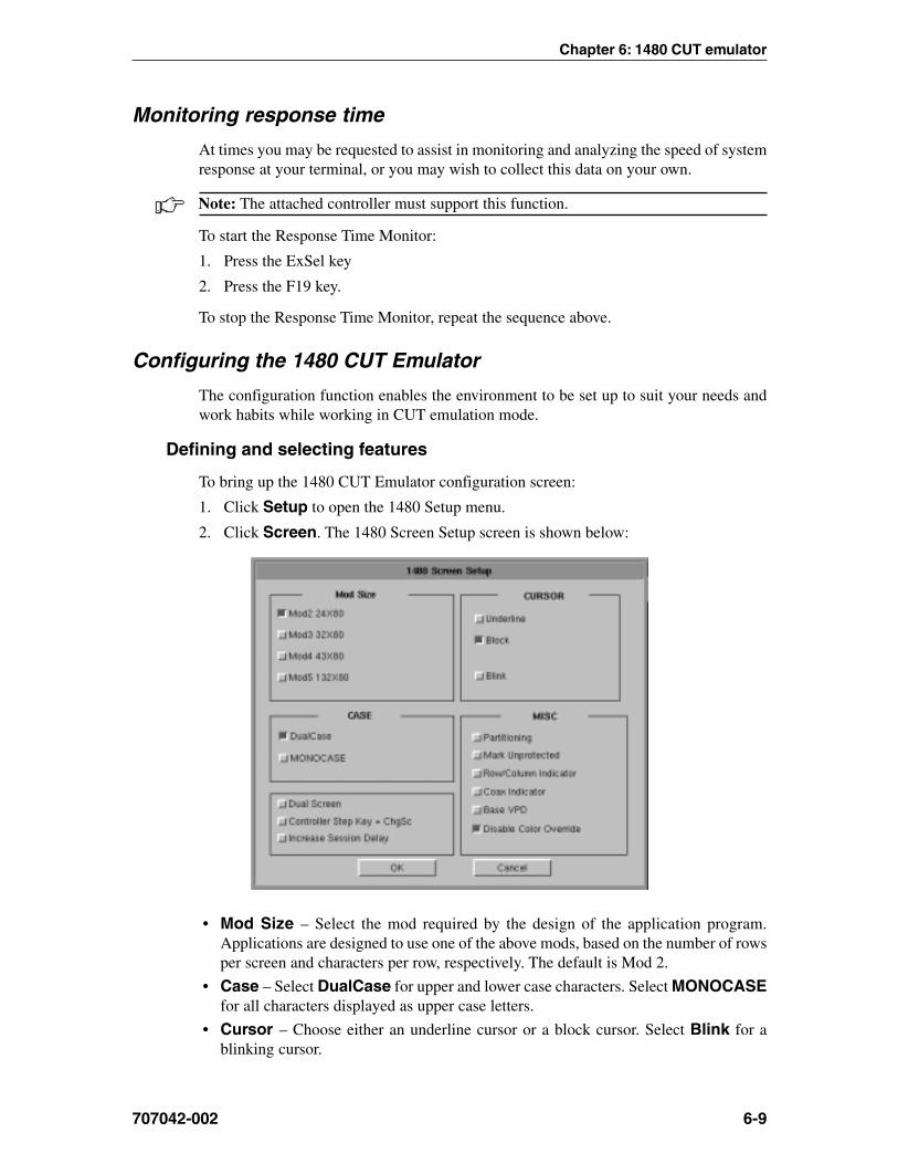
To bring up the 1480 CUT Emulator configuration screen:
1. Click Setup to open the 1480 Setup menu.
2. Click Screen. The 1480 Screen Setup screen is shown below:
• Mod Size – Select the mod required by the design of the application program.Applications are designed to use one of the above mods, based on the number of rowsper screen and characters per row, respectively. The default is Mod 2.
• Case – Select DualCase for upper and lower case characters. Select MONOCASEfor all characters displayed as upper case letters.
• Cursor – Choose either an underline cursor or a block cursor. Select Blink for ablinking cursor.

1783 Network Computing Terminal User’s Manual
6-10 707042-002
• Partitioning – This feature is not currently implemented.
• Mark Unprotected – Select to display a special symbol in each unprotected field onthe screen. This enables you to recognize locations where keystrokes can be entered.
• Row/Column Indicator – Select to display the current cursor location on the operatorstatus row. Note that the location is determined by the application program on the hostsystem.
• Coax Indicator – Select to turn the coax indicator on. When this feature is on:– A filled circle is displayed in position 71 of the status row to indicate an active
coax line.– An open circle indicates no coax activity.– A blinking circle indicates the very slow poll cycle of a coax line being
disconnected then reconnected. In that case, power down the 1783 NCT unit forat least 10 seconds before turning the power on to reestablish communications,or use the 1480 Miscellaneous Menu described later in this chapter.
The coax indicator overrides other status line information in position 71 because it isnormally used as a diagnostic feature.
• Base VPD – Select to enable the basic Vital Product Data functionality.
• Disable Color Override – Normal base color supports four colors - blue, green, redand white. A command from the controller can force the display to two base colors,green and white. Enabling this button causes the 1480 emulator to ignore the controllercommand and to display all four base colors.
• DualScreen – Enables the 1480 DualScreen feature. (See Configuring Dual ScreenMode later in this chapter for details on this and the following two options.)
• Controller Step Key = ChgSc – Enables Alt - ChgSc as the controller sessionstep key.
• Increase Session Delay – Increases the delay between changing sessions.

Chapter 6: 1480 CUT emulator
707042-002 6-11
1480 Miscellaneous
Normally the 1480 emulator is running with the coax communications active over thecoaxial cable to the mainframe host controller. For instances where the user may want tochange a configuration item such as keyboard type (104 to 122) or mod size (Mod 2 toMod 4), this screen provides the ability to make modifications to the emulator withoutpowering off the 1783 NCT and then powering it back on.
The user may make all the desired menu changes first. Some of the menu items such asthe two mentioned previously only take effect during the initial exchange of data with thecontroller.
Restarting the 1480 Emulator
To setup a remote host:
1. Click Setup in the upper left-hand corner of the screen to open the 1480 Setup menu.
2. Click Miscellaneous. The 1480 Miscellaneous screen is shown below.
3. Click Coax Stop.
4. Click the OK button. This stops the 1480 from responding to the controller.
CAUTION: All data on the 1480 screen will be lost, along with the bridge data transfersbeing stopped!
The 1480 screen data is erased and replaced by a large X. The operator symbol is placedin the status row along with another X. This shows that the communications have beenhalted.
5. Click Coax Start.
6. Click the OK button to restart the coax communications and initiate the exchange ofconfiguration items with the controller.
7. Click the Cancel button to exit this panel.

1783 Network Computing Terminal User’s Manual
6-12 707042-002
Keyboard setup
To open the Keyboard Setup panel:
1. Click Setup to open the 1480 Setup menu.
2. Click Keyboard. The Keyboard Setup screen appears:
• Keyboard Size – Select either 104 or 122-key keyboard.
• Keyboard Type – Select type of keyboard.
• Numeric Lock – If supported by the server, will allow numeric keys only for numericfields.
Click OK to save the changes and exit the screen, or Cancel to discard the changesand exit.
Note: If the keyboard size or type is changed, the coax must be stopped and restarted forthe changes to become effective.

Chapter 6: 1480 CUT emulator
707042-002 6-13
Color
To open the Color Setup Panel:
1. Click Setup to open the 1480 Setup menu.
2. Click Color. The Color Setup screen appears:
• Attributes – Use the arrows to select colors from the Colors list on the right. Selectfor protected, unprotected, normal and highlighted fields.
• Background Color – Use any or all of the three slider bars until the desired colorshows in the Background Color box and as the background of the Color Setup screen.
• Customize Colors – Use any or all of the three slider bars to adjust the colorsshowing on the Colors list.
Click OK to save the changes and exit the screen, Default to return to the system’sdefault settings, or Cancel to discard changes and exit.

1783 Network Computing Terminal User’s Manual
6-14 707042-002
Printer setup and printing
The 1480’s screen-print may be directed to either a local printer, a remote LAN printer, ora coax printer. To initiate printing once printer setup is complete, press the Print key. Toaccess the Printer Setup screen (shown below) select Printer from the 1480 Setup menu.
Print type• Coax Print – Sends the print request to the controller.
• Screen Print – Prints the entire contents of the application window.
• Screen Trim – Prints the user-selectable area within the application window. (Thisfeature is not currently implemented)
• Printer Type – Specifies the printer driver to use when printing. Options are:– Plain– HP Laserjet– Epson Inkjet– Proprinter– Postscript
Note: Printing options found on this configuration panel may vary depending on theprinter type selected.
• Draft – Prints draft quality when selected. Otherwise printing is letter quality.
• Attributes – If selected, prints intensified characters as bold and underlined whenrequired.
• Portrait – If enabled, prints in Portrait mode. If disabled, prints in Landscape mode.
• Wide Paper – If enabled, allows printing of more than 80 characters per line. Thissetting is generally used when Proprinter is selected as the Printer Type.
• CPI Selection – Specifies the number of Characters Per Inch to print. Options are10, 10.5, 12, and 17 CPI.
Chapter 6: 1480 CUT emulator
707042-002 6-15
• LPI Selection – Specifies the number of Lines Per Inch to print. Options are 3, 4, 6,8, and 8.4 LPI.
• Lines per page – Specifies the number of Lines per Page to print. Selectable rangeis 0-255.
• Line Feed – Sends an immediate Line Feed to the selected printer.
• Form Feed – Sends an immediate Form Feed to the selected printer
• HAP Menu – Displays the HAP configuration menu. The HAP menu button is graywhen HAP is disabled and green when enabled.
• LPR Menu – Displays the LPR configuration menu. The LPR menu button is graywhen LPR is disabled and green when enabled.
Coax printer assignment
To see how the 1480 printer is currently assigned, press Alt - Ident. The Assign Printercondition symbol ( ) will display on the operator status row.
:lobmysnoitidnocretnirPngissA :retnirpepytsihtsetacidnI
XXrebmunDIs’retnirpehtsixxerehw,xaoC
>>>.e.i( M C C 1 0 0 8 )
dengissanu,xaoC_ _
To assign or change a Coax printer:
1. Consult your supervisor for an available coax printer’s ID number.
2. Enter the two-digit number. The two-digit number replaces the underscore positions,or the assigned coax printer’s ID number, on the operator status row.
Once the printer’s ID number is entered, the sequence ends automatically.
If an invalid ID number is entered for a coax printer, the “What?” symbol (X ?+) appearson the operator status row. If this occurs, press Reset and try another number.

1783 Network Computing Terminal User’s Manual
6-16 707042-002
HAP Menu
The Host Addressable Print feature enables the host to send print requests to the 1783’sattached printer. LU2 (screen) prints are always formatted by the display according to theprinter menu selections. To enable or disable HAP, click the HAP Menu button fromwithin the 1480 Print Setup Screen. The Host Addressable Print configuration screen willappear:
• Enable HAP – Select to enable the HAP feature.
• Suppress Null Lines – Selection of this item will cause null lines to be removedfrom formatted (40/64/80 CPI) HAP LU3 prints. Null lines are lines that contain onlynon-printable characters (such as nulls, attributes or alphanumeric characters in a non-print field).
• Suppress automatic line feed when:– CR at MPP + 1 – If this option is selected, when the printer reaches the
Maximum Print Position + 1 (the end of the print line), the carriage returns to thebeginning of the line without a line feed. The next printed characters will overwritethe current line of printed characters. If this option is not selected, (the default),when the printer reaches the end of the line, the carriage returns to the beginningof the line and drops down one line.
– NL at MPP + 1 – If this option is selected, the printer does not execute a linefeed if there is a new line command at the Maximum Print Position + 1 (the endof the print line). The printer begins printing on the next line. If this option is notselected (the default), when the printer reaches the end of the line, it executes twoline feeds.
– FF at print end – If this option is selected, the printer does not execute a linefeed after a form feed. If this option is not selected (the default), the printerexecutes a line feed after a form feed. Characters printed on the new page beginon the second line.
Chapter 6: 1480 CUT emulator
707042-002 6-17
• FF ignored when not in first print position – If this option is selected, a formfeed character in the first position or next to the maximum print position is executedwhile form feed commands in any other positions are printed as blank characters andare otherwise ignored. If this option is not selected, all form feed commands areexecuted.
• FF takes position if followed by data – If this option is selected, and if the formfeed character is not at the end of the print data, a form feed is executed and a blankcharacter is printed in the first position on the next page. Subsequent printing starts inthe second position on the new page. If this option is not selected, the form feedcharacter is not printed as a blank character and subsequent printing starts in the firstposition on the new page.
• FF at end of print – If this option is selected, the printer ejects the last printed pageand subsequent printing begins on the new page. If this option is not selected, the lastpage is not ejected and a line feed is executed. Subsequent printing begins on the newline of the current page.
• Transparent Text Mode– Coax – data included in an SCS Transparent Mode command (35H) is printed in
the LU1 environment as follows:• Valid EBCDIC characters are translated and printed normally.• Invalid EBCDIC characters (SNA character string [SCS] commands) are
printed as hyphens.– ASCII – all data included in the command is sent through to the printer
untranslated. The following setup values are not sent to the printer duringinitialization:• Chars/Inch• Lines/Inch• Quality
• Printer Keys – Allow the operator to send either a PA1, PA2, or Cancel to theapplication. The operator selects one of the functions (PA1, PA2, or Cancel) andthen clicks the SEND button. (Cancel is effective only in LU1 type print sessions.)
Click OK to save the changes and exit the screen, or Cancel to discard the changesand exit.
Note: For changes to the HAP Menu to become effective, the 1480 must be restarted viathe Miscellaneous Menu, or by turning the unit off and back on again.

1783 Network Computing Terminal User’s Manual
6-18 707042-002
LPR Menu
To configure LPR, select the LPR Menu button from within the 1480 Print Setup Screen.The LPR Setup panel is shown below:
• Enable LPR – Select to enable LPR printing.
• LPR scroll window – used to select an LPR printer. A blue background indicatesthe printer is selected.
• Local Name – User-defined name of the printer.
• Remote Name – Queue name that print jobs are sent to from an LPR-enabled device.
• Remote Address –IP address of the selected printer.
Click OK to save the changes and exit the screen, or Cancel to discard the changesand exit.
Note: For changes to the LPR Menu to become effective, the 1480 must be restarted viathe Miscellaneous Menu, or by turning the unit off and back on again.

Chapter 6: 1480 CUT emulator
707042-002 6-19
Dual Screen feature
The 1783 dual screen feature is provided by a special software program on the main logicboard. With the 1783 NCT Display Station in 1480 Emulation mode, you can display andoperate two sessions on one monitor in either a side-by-side format or a zoomed session(that is, one of the two sessions occupies the entire display surface and you toggle betweenthe two sessions). Fields can also be copied from one session to the other. Dual screensessions are supported on a display configured as a Mod 2, 3, or 4.
Configuration requirements
To support Dual Screen mode, the controller must be configured for two or more logicalsessions on the display terminal’s port. In addition, PC File Transfer mode must be set forthose ports that use the Mark/Paste function of the 1783.
The 1783 must be configured as follows to be able to exercise the enhanced dualscreen features:
• The NCT 1480 Emulator must be in either Mod 2, 3, or 4 mode with Partitioningdeselected. (See Chapter 6: Defining and Selecting Features.)
• Host Addressable Printing must be disabled.
• The 1783 must be configured for video mode of 1024 x 768. (See Chapter 11:Configuring NCT Miscellaneous.)
Note: Only 122-key keyboards are supported.The light pen is NOT supported in Dual Screen mode.
Configuring Dual Screen mode
From the 1480 CUT Emulator application:
1. Click Setup to open the 1480 Setup menu.
2. Click Screen.
3. Click the Dual Screen button (a green button indicates that Dual Screen modeis enabled).
4. If the Controller Session Step Key is Alt - ChgSc (most 3174’s), click the ControllerStep Key button to enable it. If the controller is configured for the Session Step Keyto be Alt - Insert (most 1174’s will be configured this way) DO NOT click on theController Step Key button.
5. Click OK to save changes.
Note: If later operation of Jump and Swap keys seem to not work correctly every time,there may be a need to increase the delay between changing sessions. Click the IncreaseSession Delay button to enable it.
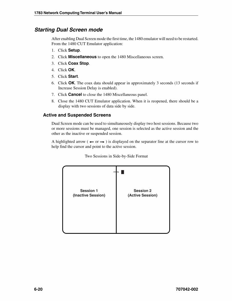
1783 Network Computing Terminal User’s Manual
6-20 707042-002
Starting Dual Screen mode
After enabling Dual Screen mode the first time, the 1480 emulator will need to be restarted.From the 1480 CUT Emulator application:
1. Click Setup.
2. Click Miscellaneous to open the 1480 Miscellaneous screen.
3. Click Coax Stop.
4. Click OK.
5. Click Start.
6. Click OK. The coax data should appear in approximately 3 seconds (13 seconds ifIncrease Session Delay is enabled).
7. Click Cancel to close the 1480 Miscellaneous panel.
8. Close the 1480 CUT Emulator application. When it is reopened, there should be adisplay with two sessions of data side by side.
Active and Suspended Screens
Dual Screen mode can be used to simultaneously display two host sessions. Because twoor more sessions must be managed, one session is selected as the active session and theother as the inactive or suspended session.
A highlighted arrow ( or ) is displayed on the separator line at the cursor row tohelp find the cursor and point to the active session.
Two Sessions in Side-by-Side Format
Session 1(Inactive Session)
Session 2(Active Session)

Chapter 6: 1480 CUT emulator
707042-002 6-21
Key assignments
Only the 122-key keyboard is supported for Dual Screen mode.
122-Key Dual Screen Keyboard Keys
Mark
Paste
StepSession
Swap Zoom
SelectLeft
SelectRight
Dual Screen Mode enhancements
The following commands and features are available in Dual Screen mode.
Zoom
Press the Zoom key ( ) to alternate the display between unzoomed (side-by-side)format and zoomed (normal) format. The zoomed format is identical to the standard Mod2, 3, or 4 format. There is only one unzoomed format for all three model types.
The zoomed session is always the currently active session. When the terminal is unzoomed,both sessions are displayed.
Select left
Press the Select Left key ( ) to position the cursor in the session on the left side of thedisplay when the display is in side-by-side format. The Select Left key operates in zoomand side-by-side modes. The session on the left side is now the active session and receivesimmediate screen updates. The session on the right side is “frozen,” which means it doesnot display new screen updates until it becomes the active session. The Select Left key hasno effect if the left side session is already active.
Select right
Press the Select Right key ( ) to position the cursor in the session on the right side ofthe display when the display is in side-by-side format. The Select Right key operates inzoom and side-by-side modes. The session on the right side is now the active session andreceives immediate screen updates. The session on the left side is “frozen,” which means

1783 Network Computing Terminal User’s Manual
6-22 707042-002
it does not display new screen updates until it becomes the active session. The SelectRight key has no effect if the right side session is already active.
Step Active session
Press and hold the Alt key while pressing the ChgSc key to change the active session tomake the next highest session the active session. The cursor does not change sides and thesession that is not selected is not affected.
For example, suppose three sessions are available. If Session 2 is the active session (thecursor is in Session 2) and is on the left and Session 1 is on the right, press the Alt - ChgSckey combination to increment the left side to Session 3. Session 3 displays on the left sideand has the cursor. Session 1 is still on the right side. If the Select Right key is pressed,Session 3 is still displayed on the left and Session 1 is still displayed on the right, but nowSession 1 has the cursor.
Example of Step Active Session
Session 1(active session)
Session 2(inactive session)
Session 2(active session)
Session 1(inactive session)
Swap session
Press and hold the Alt key while pressing the Swap key to switch sessions without movingthe cursor. For example, in side-by-side mode, if the left session is the active session (andhas the cursor), press the Alt - Swap key combination to move the left session to the rightand the right session to the left. The session on the left is still the active session and hasthe cursor.
Example of Swap Session
Session 2(active session)
Session 1(inactive session)
Session 3(active session)
Session 1(inactive session)
Chapter 6: 1480 CUT emulator
707042-002 6-23
Mark
To select a field as the source field for a subsequent paste operation, position the cursoranywhere within the field and hold down the Alt key while pressing the F4 key (Mark).See Mark/Paste below for a complete description.
Paste
To select a field as the target field and paste source data into that field, move the cursor tothe target field and hold the Alt key while pressing the F5 key (Paste). The data in thesource field is pasted into the target field. If there is already data in the target field, thatdata is overwritten with the data from the source field. See Mark, above, for instructionson how to select a source field. The target field cannot be in the same session as thesource field. See Mark/Paste below for additional information about mark and paste.
Mark/Paste
Use the Mark/Paste feature to copy data between sessions. With this feature, data canquickly be marked and pasted between fields in different sessions.
Mark field
The mark field is the field highlighted as the source data field. The data to be pasted mustbe within a displayed field. Data cannot be marked for pasting if it is in a nondisplayablefield. Data can be pasted from protected as well as unprotected fields. The mark fieldmust be selected before selecting the paste field.
To select the source or mark field, position the cursor anywhere within the field, thenpress and hold down the Alt key while pressing the F4 key (Mark). The field is displayedin reverse video to indicate it is selected. If the Mark key is pressed while a field isalready selected, the selected field is deselected. The field is also deselected after one ofthe Paste keys is pressed or if the session with the selected field is reselected with theSelect Right or Select Left key. A session with a selected field is frozen and does notreceive coax updates.
After selecting a field as the source or mark field, use the Select Left or Select Right keyto make the opposite session the active session, then move the cursor to the target field.
Paste field
The paste field is the field that receives the data from the mark field and it cannot be in thesame session as the mark field. The field that receives the pasted data must be anunprotected field. Standard data truncation rules apply when the paste and mark fields areof different lengths. If the paste field is longer than the mark field, data is replaced in thepaste field only up to the length of the mark field. If the paste field is shorter than themark field, data is truncated up to the length of the paste field. The data that has beenpasted is temporary until an Aid key (Enter or F key) is pressed; if a Select Right or SelectLeft key is pressed before an Aid key, the pasted data is lost.

1783 Network Computing Terminal User’s Manual
6-24 707042-002
Walk through
The following is an example of how to start a dual screen after configuring the 1783 NCTas described on page 6-19, Configuring Dual Screen Mode, and after following theinstructions for Starting Dual Screen Mode on page 6-20.
1. Press the Zoom ( ) key to display two side-by-side sessions.The cursor is displayed on the right side of the screen. The session on the right isnow the active session.
2. Press the Select Left ( ) key.The cursor is displayed on the left side of the screen. The session on the left is nowthe active session.
3. Log on to a host application using the session on the left side of the display.
4. Press the Zoom ( ) key.The display consists of a standard, one-session format.
5. Press the Select Right ( ) key.The session from the right side of the display becomes the active session. Thescreen is still zoomed and the right session is the only session displayed.
6. Log on to a host application using the selected right session, which is the onlysession displayed. While the logon is processing, go to Step 7.
7. Press the Zoom ( ) key.The display unzooms and consists of the side-by-side format. Wait for logonprocessing to complete.
Screen Print mode
Follow these steps to perform a screen print in Dual Screen mode:
1. Position on the left the session to be printed, using the Swap and/or Step keys ifneeded.
2. Print the screen using the normal screen print commands.
Chapter 71490 Twinax Emulator
In this Chapter...
Standard features
Communication Set Up
Screen Setup
Color Setup
Print Setup
Miscellaneous

1783 Network Computing Terminal User’s Manual
707042-0027-2
The 1490 Twinax Emulator is designed to provide a wide range of functions andapplications. Data messages are communicated between the emulator and the System/3Xor AS/400 through a twinax cable up to 1500 meters long. The 1783 equipped with a1490 emulator can be attached to any of the following processors and control units:
• IBM System/36
• IBM System/38
• IBM 5394 Control Unit
• IBM 5494 Control Unit
• IBM AS/400
The 1490 supports 122-key and 104-key keyboards..
You can generate hard copy by attaching a twinax printer to the System/3X or AS/400 orby attaching a host addressable printer to the 1783 equipped with a 1490 emulator. TheLocal Screen Print feature enables you to make a hard copy of the displayed text.
Standard Features• Multiple Emulations – The 1490 can emulate several different display types. Both
monochrome and color displays can be emulated. For display stations attached to aSystem/36 or System/38, a 132-column color format can be selected.
• Two-Host Sessions – You can configure one host display sessions and one printerhost session that run concurrently.
• Full-Screen Setup Menus – The full-screen setup menus offer simplicity and easeof use for all setup functions.
• User Selectable Color Mixing – With the color 1490, you can select the shades ofthe colors for the attributes.
• Audible Alarm – Sounds when the host system signals the display station.
• MVP (Multivendor printers) – The 1490 supports a wide variety of industry standardprinters.
• Optional Features• US English
– 104-Key EBCDIC US English Typewriter
– 122-Key 5250 US English Typewriter
– 122-Key 3270 US English Typewriter

Chapter 7: 1490 Twinax Emulator
707042-002 7-3
Communication Setup
Terminal Mode
Consult the system operator before changing this option.
The 1783 in 1490 mode can operate in two different terminal modes. By enabling up totwo independent host sessions to be configured, each with a different address on thesystem, multiple host functions can be active simultaneously.
• One-Display – The 1490 operates as a single display station with one address. Thisis the default setting. Local screen printing is available.
• One-Display-Printer – Both the display and attached printer are logically connectedto the host, each having a different address. In this mode, host addressable printing isenabled.
Display Address
The display address is the display station’s logical address on the System/3X or AS/400port. Ask the system supervisor for this address. The 1490 will not operate online untilyou enter this address. No default address is set at the factory.
noitceleS noitpircseD
60hguorht00morfsserddanatceleS 00 hguorht 60 emasehtngissatonoD.
.retnirpadnayalpsidarofsserdda
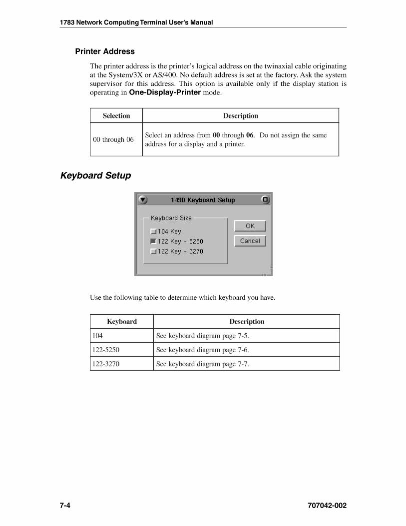
1783 Network Computing Terminal User’s Manual
707042-0027-4
Printer Address
The printer address is the printer’s logical address on the twinaxial cable originatingat the System/3X or AS/400. No default address is set at the factory. Ask the systemsupervisor for this address. This option is available only if the display station isoperating in One-Display-Printer mode.
noitceleS noitpircseD
60hguorht00morfsserddanatceleS 00 hguorht 60 emasehtngissatonoD.
.retnirpadnayalpsidarofsserdda
Keyboard Setup
Use the following table to determine which keyboard you have.
draobyeK noitpircseD
401 .5-7egapmargaiddraobyekeeS
0525-221 .6-7egapmargaiddraobyekeeS
0723-221 .7-7egapmargaiddraobyekeeS

Chapter 7: 1490 Twinax Emulator
707042-002 7-5
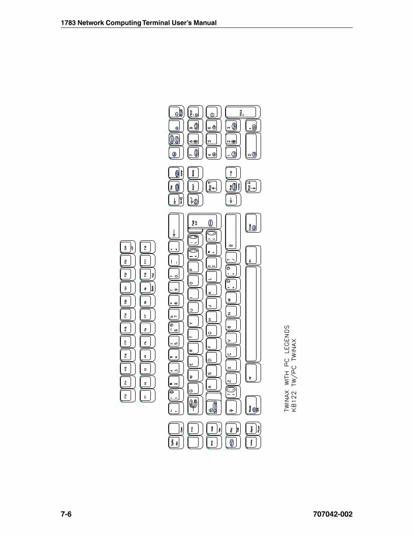
1783 Network Computing Terminal User’s Manual
707042-0027-6

Chapter 7: 1490 Twinax Emulator
707042-002 7-7

1783 Network Computing Terminal User’s Manual
707042-0027-8
Screen Setup
Display Emulation
noitceleS noitpircseD
CledoM7743
dednetxEstroppusnoitalumesihT.yalpsidrolocnmuloc-231noitstsyalpsidrofnoitalumesihttceleS.setubirttaretcarahc
rolocrofgnittestluafedehtsisihT.004/SAnaotdehcatta.srotinomrolochtiwylnoelbaliavasidnasrotinom
DledoM7743
stroppusnoitalumesihT.yalpsidemorhconomnmuloc231yalpsidrofnoitalumesihttceleS.setubirttaretcarahCdednetxE
rofgnittesstluafedehtsisihT.004/SAnaotdehcattanoitatsdnarolochtobhtiwelbaliavasidnasrotinomemorhconom
.srotinomemorhconom
DledoM79132ledoM0813
esehtfoenotceleS.yalpsidemorhconomnmuloc-231dehcattasnoitatsyalpsidroftroppusnmuloc-231rofsnoitalume
dnarolochtobhtiwelbaliavasinoitposihT.X3/metsySaot.srotinomemorhconom
6913htiwelbaliavasinoitposihT.yalpsidemorhconomnmuloc-08
.srotinomemorhconomdnarolochtob
2ledoM7913htiwelbaliavasinoitposihT.yalpsidemorhconomnmuloc-08
.srotinomrolocylno
CledoM7843 .yalpsidrolocnmuloc-231
GledoM7843 .yalpsidemorhconomnmuloc-231

Chapter 7: 1490 Twinax Emulator
707042-002 7-9
By selecting one of the 132-column monochrome emulations, you can enable a 1490display station attached to a System/3X to have 132-column capability, even though theSystem/3X does not support 132-column color displays.
The Display Emulation option is also useful when installing and configuring deviceswhere system support services are not readily available (for example, at a remote site).You can select the emulation of the display that is already configured on your systemwithout having to change the host configuration.
Cursor
noitceleS noitpircseD
kcolB (kcolbastceleS � .gnittestluafedehtsisihT.)
enilrednU .)_(rosrucenilrednunastceleS
knilBsirosrucehtesiwrehtO.knilblliwrusrucehtdetcelesnehW
.dilos
neercSlluF
ehttaneddiheblliwrabunemehT.edomneercslluftceleSybneddihnuebnacrabunemehT.tesernorewoptxen
rodraobyekyek221anoyek"putes"ehtgnisserped.draobyekyek401ano"retnedapyekciremun-tlA"
Note: Underline and Block cursor mode are mutually exclusive.
Full Screen Mode
noitceleS noitpircseD
neercSlluF
ehttaneddiheblliwrabunemehT.edomneercslluftceleSybneddihnuebnacrabunemehT.tesernorewoptxen
rodraobyekyek221anoyek"putes"ehtgnisserped.draobyekyek401ano"retnedapyekciremun-tlA"

1783 Network Computing Terminal User’s Manual
707042-0027-10
Color Setup
• Colors – Use to select a color you desire as background or designated text.
• Background Color – Use any or all of the three slider bars until the desired colorshows in the Background Color box and as the background of this screen.
• Customize Colors – Use any or all three slider bars to adjust the colors showing onthe color list.
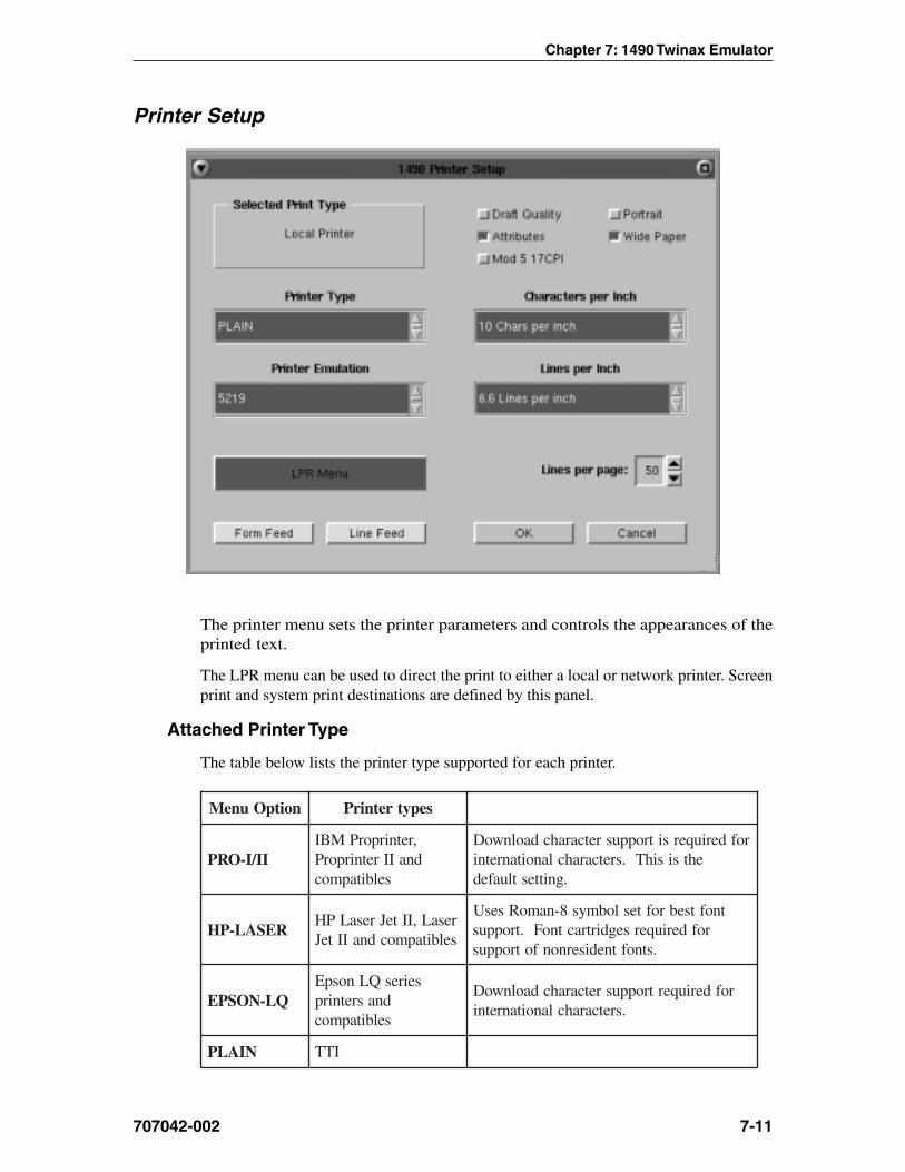
Chapter 7: 1490 Twinax Emulator
707042-002 7-11
Printer Setup
The printer menu sets the printer parameters and controls the appearances of theprinted text.
The LPR menu can be used to direct the print to either a local or network printer. Screenprint and system print destinations are defined by this panel.
Attached Printer Type
The table below lists the printer type supported for each printer.
noitpOuneM sepytretnirP
II/I-ORP,retnirporPMBIdnaIIretnirporP
selbitapmoc
rofderiuqersitroppusretcarahcdaolnwoDehtsisihT.sretcarahclanoitanretni
.gnittestluafed
RESAL-PHresaL,IIteJresaLPHselbitapmocdnaIIteJ
tnoftsebrofteslobmys8-namoRsesUrofderiuqersegdirtractnoF.troppus
.stnoftnedisernonfotroppus
QL-NOSPEseiresQLnospE
dnasretnirpselbitapmoc
rofderiuqertroppusretcarahcdaolnwoD.sretcarahclanoitanretni
NIALP ITT
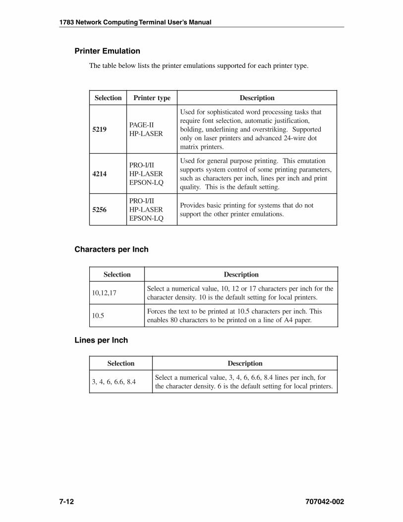
1783 Network Computing Terminal User’s Manual
707042-0027-12
Printer Emulation
The table below lists the printer emulations supported for each printer type.
noitceleS epytretnirP noitpircseD
9125II-EGAP
RESAL-PH
tahtsksatgnissecorpdrowdetacitsihposrofdesU,noitacifitsujcitamotua,noitcelestnoferiuqer
detroppuS.gnikirtsrevodnagninilrednu,gnidlobtoderiw-42decnavdadnasretnirpresalnoylno
.sretnirpxirtam
4124II/I-ORP
RESAL-PHQL-NOSPE
noitatumesihT.gnitnirpesopruplarenegrofdesU,sretemarapgnitnirpemosfolortnocmetsysstroppus
tnirpdnahcnirepsenil,hcnirepsretcarahcsahcus.gnittestluafedehtsisihT.ytilauq
6525II/I-ORP
RESAL-PHQL-NOSPE
tonodtahtsmetsysrofgnitnirpcisabsedivorP.snoitalumeretnirprehtoehttroppus
Characters per Inch
noitceleS noitpircseD
71,21,01ehtrofhcnirepsretcarahc71ro21,01,eulavlaciremunatceleS
.sretnirplacolrofgnittestluafedehtsi01.ytisnedretcarahc
5.01sihT.hcnirepsretcarahc5.01tadetnirpebottxetehtsecroF
.repap4Afoenilanodetnirpebotsretcarahc08selbane
Lines per Inch
noitceleS noitpircseD
4.8,6.6,6,4,3rof,hcnirepsenil4.8,6.6,6,4,3,eulavlaciremunatceleS
.sretnirplacolrofgnittestluafedehtsi6.ytisnedretcarahceht
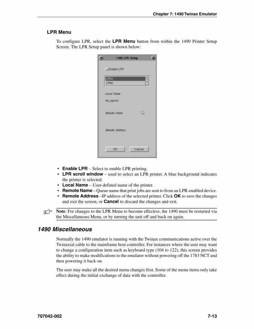
Chapter 7: 1490 Twinax Emulator
707042-002 7-13
LPR Menu
To configure LPR, select the LPR Menu button from within the 1490 Printer SetupScreen. The LPR Setup panel is shown below:
• Enable LPR – Select to enable LPR printing.• LPR scroll window – used to select an LPR printer. A blue background indicates
the printer is selected.• Local Name – User-defined name of the printer.• Remote Name – Queue name that print jobs are sent to from an LPR-enabled device.• Remote Address –IP address of the selected printer. Click OK to save the changes
and exit the screen, or Cancel to discard the changes and exit.
Note: For changes to the LPR Menu to become effective, the 1490 must be restarted viathe Miscellaneous Menu, or by turning the unit off and back on again.
1490 Miscellaneous
Normally the 1490 emulator is running with the Twinax communications active over theTwinaxial cable to the mainframe host controller. For instances where the user may wantto change a configuration item such as keyboard type (104 to 122), this screen providesthe ability to make modifications to the emulator without powering off the 1783 NCT andthen powering it back on.
The user may make all the desired menu changes first. Some of the menu items only takeeffect during the initial exchange of data with the controller.

1783 Network Computing Terminal User’s Manual
707042-0027-14
Restarting the 1490 Emulator1. Click Setup in the upper left-hand corner of the screen to open the 1490 Setup menu.
2. Click Miscellaneous. The 1490 Miscellaneous screen is shown below.
3. Click Stop Twinax.
4. Click the OK button. This stops the 1490 from responding to the controller and themenu will be removed from the screen.
CAUTION: All data on the 1490 screen and unprinted data will be lost.
When 1490 screen data is erased the Miscellaneous panel will disappear and the cursor isplaced in the upper right corner of the screen.
5. To open the miscellaneous menu, repeat steps 1 and 2.
6. Click Start Twinax.
7. Click the OK button to restart the Twinax communications and initiate the exchangeof configuration items with the controller.

Chapter 8Using Telnet, TN3270, TN5250 and VT220
In this Chapter...
Telnet Terminal
TN3270
TN5250
VT220
1783 Network Computing Terminal User’s Manual
707042-0028-2
Telnet Terminal
What is Telnet?
Telnet, using the Telnet protocol and the Internet, enables the user to gain access tocomputer systems around the world.
In effect, the 1783 NCT functions as though it were a terminal connected to a remotehost. Once logged in, whatever tools are provided on the host can be used to do a varietyof things, such as:
• search databases to locate targeted information
• run specialized programs
• enter into online discussions
Telnet makes it possible for your terminal to “look like” whatever terminal the hostnormally supports. An exception is certain IBM mainframe hosts running 3270applications. To access a host as a 3270-type terminal, use the TN3270 feature, describedlater in this section.
To gain permission to access a remote host, you can look up standard userids distributedby those hosts whose administrators encourage public access, or you can set up an accountwith a host and acquire a private userid and password. Some host administrators set upaccess so that you can log in directly without a userid or password. Some provide specialport identifiers that need to be used.
In all cases, the host name of the computer system you wish to access is required.
Logging in to a remote host
To connect and log in to a remote host:
1. Click the button in the lower left hand corner of the screen. The applicationmenu will appear.
2. Click Telnet to start a Telnet session.
You will see this prompt in the window:
telnet >
Type:open host
where host is the official name, an alias, or the Internet address of thecomputer system to which you wish to connect. For example,open {host}.{domain}.com
Note: If the host requires that a port number be specified when connecting, simply appendthe port number to the host name, separated by a space.
Chapter 8: Using Telnet, TN3270, TN5250 and VT220
707042-002 8-3
Telnet will connect to the remote host. The host then will normally respond with a welcomeand will lead you through its log in process. Log in, employing one of the followingcombinations:
• With the userid and password supplied by the administrator of the host
• With just a userid (some hosts do not require passwords)
• Neither, if the remote host has been set up for it.
Once connected, use the menus, commands and features of the remote host, which arelargely text-based and can vary from host to host.
Logging out of a remote host
When you are finished using the remote host, use that host’s normal log out command.Telnet will automatically finish running.
To disconnect from the host when its log out command is not available, or if you are stuckfor any other reason, enter one of the following:
• Ctrl - ]
• the escape character displayed by the host upon logging in.
Recommended reference guides
Telnet enables many special telecommunication features to be configured, such as howcarriage returns or interrupts are processed. Such features may be needed when accessinga non-Unix remote host. Contact your system administrator or refer to one of thefollowing references:
Hunt, Craig, TCP/IP Network Administration, O’Reilly & Associates, Inc.,Cambridge, MA.
Heywood, Drew; Jerney, Janos; Johnston, Jon, et al, Connectivity: Local Area Networks,New Riders Publishing, Carmel, IN.

1783 Network Computing Terminal User’s Manual
707042-0028-4
TN3270
What is TN3270?
Like Telnet, TN3270 enables access to programs running on remote hosts. Unlike Telnet,TN3270 provides the means to access 3270 programs running on IBM mainframes.
TN3270 enables the 1783 NCT to function as though it were a 3279 mod 2, mod 3, mod4, or mod 5 terminal. Unlike Telnet, TN3270 can manipulate the entire screen image,fields and function keys, in a way identical to a 3270 terminal. TN3270 provides thefollowing standard features:
• Window Menus – The window menus offer simplicity and ease of use for all setupfunctions.
• Color Display – The color monitor is programmable in seven colors.
• Switchable Screen Formats – TN3270 supports four (4) screen sizes that can beselected from setup menus. The server to which the TN3270 client attaches must beconfigured to support the screen size used. Check with your system administrator.
• Mono/DualCase Mode – Allows characters to be displayed as all uppercasecharacters or as upper- and lowercase characters.
• Mark Unprotected Field Indicator – The 1480 CUT Emulator can be requestedto mark unprotected fields with a special character.
• Row/Column Indicator – Displays the current cursor location on the operatorstatus row.
• Numeric Lock – Allows a field to be defined to accept only numeric characters andthe Period, Minus, and Dup keys. The comma may be substituted for the period onsome international keyboards.
• Multiple Sessions – A maximum of 10 sessions can be accessed with this emulator.

Chapter 8: Using Telnet, TN3270, TN5250 and VT220
707042-002 8-5
Setting up a remote host as a 3270 terminal
To setup a remote host:
1. Click the button in the lower left-hand corner of the screen. The applicationmenu will appear.
2. Click TN3270. The main TN3270 screen will appear with two menu options, Setupand Session.
3. Click Setup.4. Click Communications from the Setup menu. This screen will appear:
• Session Type – Select Display to configure a TN3270 Display session. SelectPrinter to configure a TN3287 Printer session.
• Session Name – Enter the name to be displayed in the window title.
• Host – Enter the Internet address of the TN3270 server to which you wish to connect,for example, 255.255.XXX.XXX.
• Port – If the host requires that a port number (other than port 23) be specified whenconnecting, select the port number using the up and down arrows or by typing the portin directly.
• Enable TN3270E – Select to enable TN3270E support.
• LU Name – Enter LU name string (optional, for TN3270E).
• Auto Connect – Select to auto connect at program start and to reconnect automaticallyif disconnected by the server.
Click OK to save changes and close Communications Setup, or Cancel to close anddiscard any changes.

1783 Network Computing Terminal User’s Manual
707042-0028-6
Connecting to a TN3270 session
TN3270 will connect to the remote IBM mainframe host. The host then will normallyrespond with a welcome and will lead you through its log in process. Log in, employingone of the following combinations:
• With the userid and password supplied by the administrator of the host
• With just a userid (some hosts do not require passwords)
• Neither, if the remote host has been set up for it.
To connect to a TN3270 remote host from the main TN3270 screen:
1. Click Session to open the TN3270 Session menu.
2. Click Connect.
Once connected, use the menus, commands and features of the remote host to access andrun 3270 applications.
Logging out of a remote host1. When you have finished using the remote host, use the host’s normal log out command.
2. To disconnect from the host, select Disconnect from the Session menu.

Chapter 8: Using Telnet, TN3270, TN5250 and VT220
707042-002 8-7
TN
3270
104-
key
Key
boar
d L
ayou
t

1783 Network Computing Terminal User’s Manual
707042-0028-8
TN
3270
122-
key
Key
boar
d L
ayou
t

Chapter 8: Using Telnet, TN3270, TN5250 and VT220
707042-002 8-9
Configuring TN3270 for an application
TN3270 can be configured for a particular application by selecting Screen, Keyboardor Color from the Setup menu.
Screen setup
From the main TN3270 application screen:
1. Click Setup to open the TN3270 Setup menu.
2. Click Screen.
• Mod Size – Select the mod required by the design of the application program.Applications are designed to use one of the above mods, based on the number of rowsper screen and characters per row, respectively. The default is Mod 2.
• Case – Select DualCase for upper and lower case characters. Select MONOCASEfor all characters displayed as upper case letters.
• Edit Select Mode – Choose either Standard Select or Frame Select. Standardselect performs an end-of-line wrap function when selecting text. Frame Select isused to a specific block of text without automatically performing an end-of-line wrapfunction.
• Cursor – Choose either an underline cursor or a block cursor. Select Blink for ablinking cursor.
• Mark Unprotected – Select to display a special symbol in each unprotected field onthe screen. This enables you to recognize locations where keystrokes can be entered.
• Row/Column Indicator – Select to display the current cursor location on the operatorstatus row. Note that the location is determined by the application program on the host system.
• Full Screen Mode – Select to open the TN3270 application in Full Screen Mode.TN3270 must be closed and reopened for this setting to become effective.
Note: To access the taskbar or minimized applications on the taskbar while Full ScreenMode is in effect, hold down the Ctrl and Alt keys while pressing the tab key. Press the tabkey repeatedly until the name of the application you wish to bring to the front is displayed.
Click OK to save changes and close Screen Setup, or Cancel to close and discardany changes.

1783 Network Computing Terminal User’s Manual
707042-0028-10
Keyboard setup
From the main TN3270 application screen:
1. Click Setup to open the TN3270 Setup menu.
2. Click Keyboard.
• Keyboard Size – Select either the 104 or 122-key keyboard.
• Disable Keyboard Macros – Prevents the user from assigning user-defined macrofunctions to keys.
• Numeric lock – If supported by the TN3270 server, will allow numeric keys only fornumeric fields.
• Typeahead – Enable the Typeahead feature.
• Key Mapper – The key assignment (mapping) may be verified or changed asnecessary for use in TN3270 applications.
Keyboard Mapper
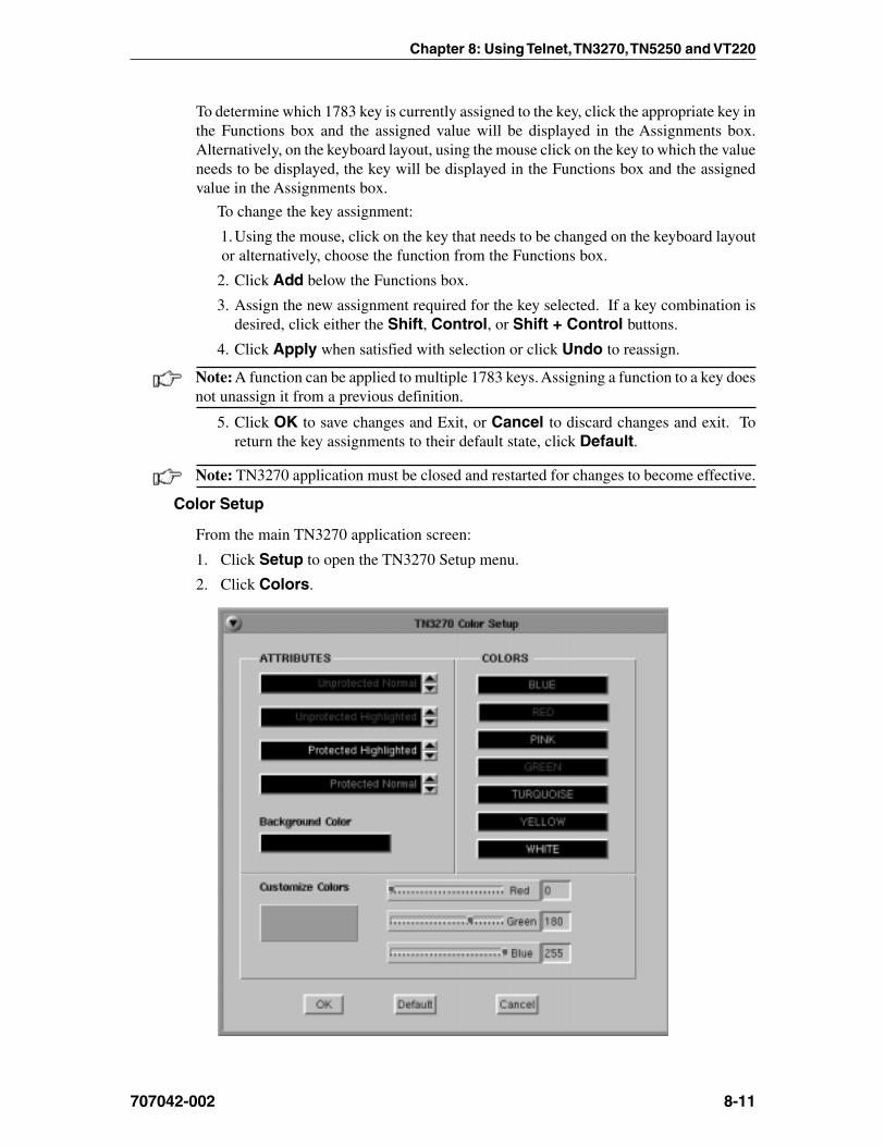
Chapter 8: Using Telnet, TN3270, TN5250 and VT220
707042-002 8-11
To determine which 1783 key is currently assigned to the key, click the appropriate key inthe Functions box and the assigned value will be displayed in the Assignments box.Alternatively, on the keyboard layout, using the mouse click on the key to which the valueneeds to be displayed, the key will be displayed in the Functions box and the assignedvalue in the Assignments box.
To change the key assignment:
1.Using the mouse, click on the key that needs to be changed on the keyboard layoutor alternatively, choose the function from the Functions box.
2. Click Add below the Functions box.
3. Assign the new assignment required for the key selected. If a key combination isdesired, click either the Shift, Control, or Shift + Control buttons.
4. Click Apply when satisfied with selection or click Undo to reassign.
Note: A function can be applied to multiple 1783 keys. Assigning a function to a key doesnot unassign it from a previous definition.
5. Click OK to save changes and Exit, or Cancel to discard changes and exit. Toreturn the key assignments to their default state, click Default.
Note: TN3270 application must be closed and restarted for changes to become effective.
Color Setup
From the main TN3270 application screen:
1. Click Setup to open the TN3270 Setup menu.
2. Click Colors.

1783 Network Computing Terminal User’s Manual
707042-0028-12
• Attributes – Use the arrows to select colors from the Colors list on the right. Selectfor protected, unprotected, normal and highlighted fields.
• Customize Colors – Select a color from the colors list. Use any or all of the threeslider bars to adjust the selected color.
• Background color – Select the Background Color bar, then apply any or all of thethree slider bars until the desired color shows in the Background Color box.
Click OK to save changes and close Color Setup, or Cancel to close and discardany changes.
Print setup
To access the Print Setup screen (shown below) from the main TN3270 screen:
1. Click Setup to open the TN3270 Setup menu.
2. Click Printer.
Print type
• Screen print – Prints the entire contents of the application window• Printer Type – Specifies the printer driver to use when printing. Options are:
– Plain– HP Laserjet– Epson Inkjet– Proprinter– Postscript
Note: Printing options found on this configuration panel may vary depending on theprinter type selected.
• Draft – Prints draft quality when selected. Otherwise printing is letter quality.• Attributes – If selected, prints intensified characters as bold and underlined
when required.• Portrait – If enabled, prints in Portrait mode. If disabled, prints in Landscape mode.

Chapter 8: Using Telnet, TN3270, TN5250 and VT220
707042-002 8-13
• Mod 5 17 CPI – If selected, printing automatically changes to 17 CPI (characters perinch) if the application screen is Mod 5.
• Wide Paper – If enabled, allows printing of more than 80 characters per line. Thissetting is generally used when Proprinter is selected as the Printer Type.
• CPI Selection – Specifies the number of Characters Per Inch to print. Options are10, 10.5, 12, and 17 CPI.
• LPI Selection – Specifies the number of Lines Per Inch to print. Options are 3, 4, 6,8, and 8.4 LPI.
• Lines per page – Specifies the number of Lines per Page to print. Selectable rangeis 0-255.
• Line Feed – Sends an immediate Line Feed to the selected printer.
• Form Feed – Sends an immediate Form Feed to the selected printer
• LPR Menu – Displays the LPR configuration menu. The LPR menu button is graywhen LPR is disabled and green when enabled.
LPR menu
To configure LPR, select the LPR Menu button. The LPR Setup panel is shown below:
• Enable LPR – Select to enable LPR printing.• LPR scroll window – Used to select an LPR printer. A blue background indicates
the printer is selected.• Local Name – User-defined name of the printer.• Remote Name – Queue name that print jobs are sent to from an LPR-enabled device.• Remote Address – IP address of the selected printer.
Click OK to save changes and exit, or Cancel to exit and discard any changes.
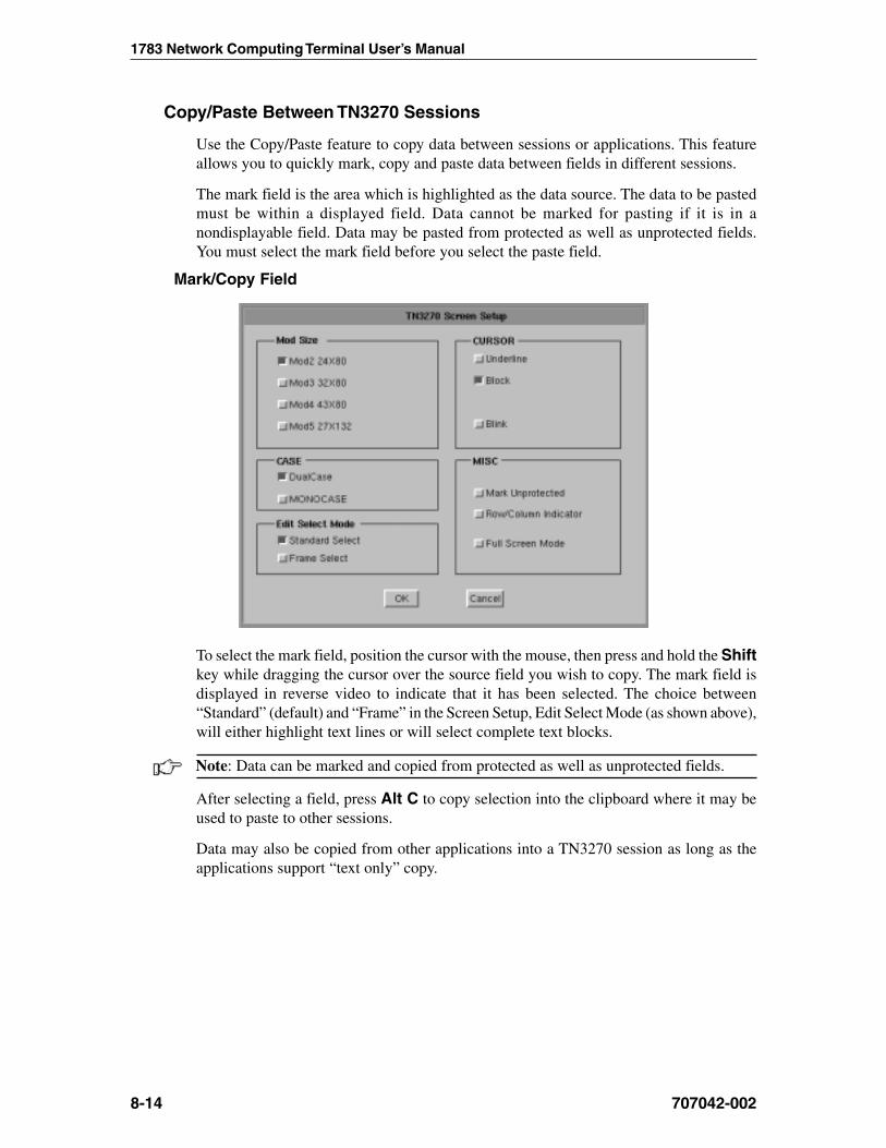
1783 Network Computing Terminal User’s Manual
707042-0028-14
Copy/Paste Between TN3270 Sessions
Use the Copy/Paste feature to copy data between sessions or applications. This featureallows you to quickly mark, copy and paste data between fields in different sessions.
The mark field is the area which is highlighted as the data source. The data to be pastedmust be within a displayed field. Data cannot be marked for pasting if it is in anondisplayable field. Data may be pasted from protected as well as unprotected fields.You must select the mark field before you select the paste field.
Mark/Copy Field
To select the mark field, position the cursor with the mouse, then press and hold the Shiftkey while dragging the cursor over the source field you wish to copy. The mark field isdisplayed in reverse video to indicate that it has been selected. The choice between“Standard” (default) and “Frame” in the Screen Setup, Edit Select Mode (as shown above),will either highlight text lines or will select complete text blocks.
Note: Data can be marked and copied from protected as well as unprotected fields.
After selecting a field, press Alt C to copy selection into the clipboard where it may beused to paste to other sessions.
Data may also be copied from other applications into a TN3270 session as long as theapplications support “text only” copy.

Chapter 8: Using Telnet, TN3270, TN5250 and VT220
707042-002 8-15
Paste Field
The paste field is the field that receives the data from the mark field. The paste field mustbe an unprotected field. Standard data truncation rules apply when the paste and markfields are of different lengths. If the paste field is longer than the mark field, data isreplaced in the paste field only up to the length of the mark field. If the paste field isshorter than the mark field, data is truncated up to the length of the paste field. The datathat has been pasted is temporary until you press an Aid key (Enter or F key). To paste thedata you select using the Copy/Paste, position the cursor with the mouse and press Alt V.
Copy/Paste From Calculator to TN3270 Session
All entries on the calculator are automatically stored into the clipboard, therefore, there isno need to copy the field. Perform the calculation you require, switch back to the sessionand place the cursor where the data is required. Press Alt V to paste the calculated field.
Note: Every entry on the calculator overrides the buffer in the clipboard. Only the lastentry/calculation is available.
Recommended reference guide
TN3270 allows you to configure special features and to temporarily suspend/resume ahost session. You may need to configure new 3278 models as support for them becomesavailable, or you may need more information on controlling a host session. Contact yoursystem administrator or refer to the following reference:“Yale ASCII Terminal Communication,” System II Program Description/Operator’s Manual(IBM SB30-1911).
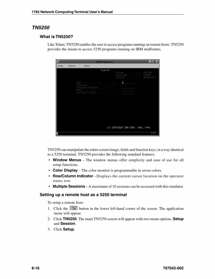
1783 Network Computing Terminal User’s Manual
707042-0028-16
TN5250
What is TN5250?
Like Telnet, TN5250 enables the user to access programs running on remote hosts. TN5250provides the means to access 5250 programs running on IBM midframes.
TN5250 can manipulate the entire screen image, fields and function keys, in a way identicalto a 5250 terminal. TN5250 provides the following standard features:
• Window Menus – The window menus offer simplicity and ease of use for allsetup functions.
• Color Display – The color monitor is programmable in seven colors.
• Row/Column Indicator – Displays the current cursor location on the operatorstatus row.
• Multiple Sessions – A maximum of 10 sessions can be accessed with this emulator.
Setting up a remote host as a 5250 terminal
To setup a remote host:
1. Click the button in the lower left-hand corner of the screen. The applicationmenu will appear.
2. Click TN5250. The main TN5250 screen will appear with two menu options, Setupand Session.
3. Click Setup.
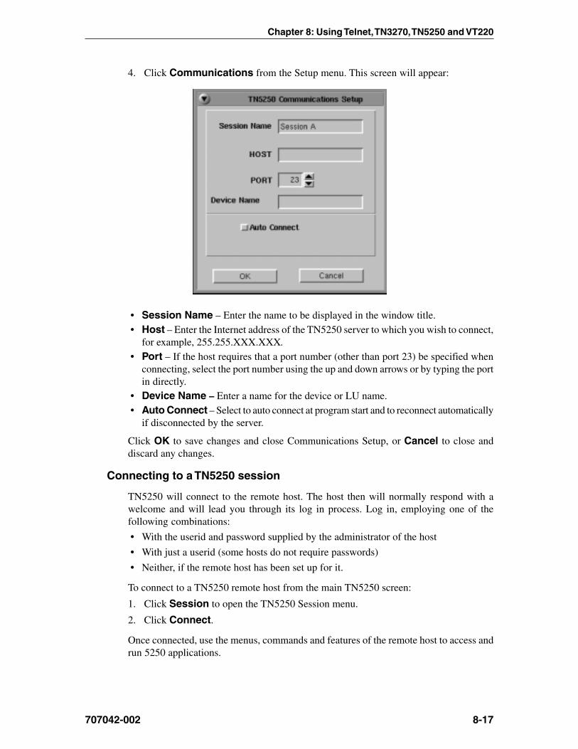
Chapter 8: Using Telnet, TN3270, TN5250 and VT220
707042-002 8-17
4. Click Communications from the Setup menu. This screen will appear:
• Session Name – Enter the name to be displayed in the window title.• Host – Enter the Internet address of the TN5250 server to which you wish to connect,
for example, 255.255.XXX.XXX.
• Port – If the host requires that a port number (other than port 23) be specified whenconnecting, select the port number using the up and down arrows or by typing the portin directly.
• Device Name – Enter a name for the device or LU name.• Auto Connect – Select to auto connect at program start and to reconnect automatically
if disconnected by the server.
Click OK to save changes and close Communications Setup, or Cancel to close anddiscard any changes.
Connecting to a TN5250 session
TN5250 will connect to the remote host. The host then will normally respond with awelcome and will lead you through its log in process. Log in, employing one of thefollowing combinations:
• With the userid and password supplied by the administrator of the host
• With just a userid (some hosts do not require passwords)
• Neither, if the remote host has been set up for it.
To connect to a TN5250 remote host from the main TN5250 screen:
1. Click Session to open the TN5250 Session menu.
2. Click Connect.
Once connected, use the menus, commands and features of the remote host to access andrun 5250 applications.

1783 Network Computing Terminal User’s Manual
707042-0028-18
TN
5250
104-
key
Key
boar
d L
ayou
t

Chapter 8: Using Telnet, TN3270, TN5250 and VT220
707042-002 8-19
TN
5250
122-
key
Key
boar
d L
ayou
t

1783 Network Computing Terminal User’s Manual
707042-0028-20
Logging out of a remote host1. When you have finished using the remote host, use the host’s normal log out command.
2. To disconnect from the host, select Disconnect from the Session menu.
Configuring TN5250 for an application
TN5250 can be configured for a particular application by selecting Screen, Keyboardor Color from the Setup menu.
Screen setup
From the main TN5250 application screen:
1. Click Setup to open the TN5250 Setup menu.
2. Click Screen.
• Cursor – Choose either an underline cursor or a block cursor. Select Blink for ablinking cursor.
• Full Screen Mode – Select to open the TN5250 application in Full Screen Mode.TN5250 must be closed and reopened for this setting to become effective.
Note: To access the taskbar or minimized applications on the taskbar while Full ScreenMode is in effect, hold down the Ctrl and Alt keys while pressing the tab key. Press the tabkey repeatedly until the name of the application you wish to bring to the front is displayed.
Click OK to save changes and close Screen Setup, or Cancel to close and ignoreany changes.

Chapter 8: Using Telnet, TN3270, TN5250 and VT220
707042-002 8-21
Keyboard setup
From the main TN5250 application screen:
1. Click Setup to open the TN5250 Setup menu.
2. Click Keyboard.
• Keyboard Size – Select either 104 or 122-key keyboard.
• Typeahead – Enable the Typeahead feature.
• Keyboard Mapper – The key assignment (mapping) may be verified or changedas necessary for use in TN5250 applications.
Keyboard Mapper
To determine which 1783 key is currently assigned to the key, click the appropriate key inthe Functions box and the assigned value will be displayed in the Assignments box.
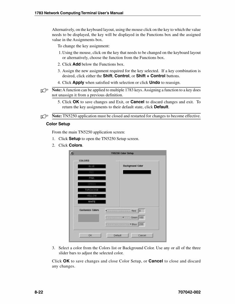
1783 Network Computing Terminal User’s Manual
707042-0028-22
Alternatively, on the keyboard layout, using the mouse click on the key to which the valueneeds to be displayed, the key will be displayed in the Functions box and the assignedvalue in the Assignments box.
To change the key assignment:
1.Using the mouse, click on the key that needs to be changed on the keyboard layoutor alternatively, choose the function from the Functions box.
2. Click Add below the Functions box.
3. Assign the new assignment required for the key selected. If a key combination isdesired, click either the Shift, Control, or Shift + Control buttons.
4. Click Apply when satisfied with selection or click Undo to reassign.
Note: A function can be applied to multiple 1783 keys. Assigning a function to a key doesnot unassign it from a previous definition.
5. Click OK to save changes and Exit, or Cancel to discard changes and exit. Toreturn the key assignments to their default state, click Default.
Note: TN5250 application must be closed and restarted for changes to become effective.
Color Setup
From the main TN5250 application screen:
1. Click Setup to open the TN5250 Setup screen.
2. Click Colors.
3. Select a color from the Colors list or Background Color. Use any or all of the threeslider bars to adjust the selected color.
Click OK to save changes and close Color Setup, or Cancel to close and discardany changes.

Chapter 8: Using Telnet, TN3270, TN5250 and VT220
707042-002 8-23
VT220
What is VT220?
Like Telnet, VT220 enables you to access programs running on remote hosts.
Welcome to HAL, a DEC 3000 Model 300 (AXP) running VMS version V6.1
Username: _
VT220 enables the 1783 NCT to function as though it were a standard VT220 display.VT220 provides the following standard features:
• Window Menus – The window menus offer simplicity and ease of use for all setupfunctions.
• Color Display – The color monitor is programmable.
• Multiple Sessions – A maximum of 10 sessions can be accessed with this emulator.
Setting up VT220
To setup a remote host:
1. Click the button in the lower left-hand corner of the screen. The applicationmenu will appear.
2. Click VT220. The main VT220 screen will open with two menu options, Setup andSession.
3. Click Setup.

1783 Network Computing Terminal User’s Manual
707042-0028-24
4. Click Communications from the Setup menu. This screen will appear:
• Connection Type – Select either a LAN or Serial connection.
• LAN– Host – Enter the Internet address of the VT220 server to which you wish to
connect, for example, 255.255.XXX.XXX.– Port – If the host requires that a port number (other than port 23) be specified
when connecting, select the port number using the up and down arrows or bytyping the port in directly.
• Auto Connect – Select to auto connect at program start-up.
• Session Name – Enter the name to be displayed in the window title.
• Serial – Select the Baud rate, parity, data bits and stop bits for the serial connection.
• Configure – Select to display the Serial Communications Configuration Panel.
Click OK to save changes and close Communications Setup, or Cancel to close anddiscard any changes.
Chapter 8: Using Telnet, TN3270, TN5250 and VT220
707042-002 8-25
Connecting to a VT220 session
VT220 will connect to the remote host. The host then will normally respond with a welcomeand will lead you through its log in process. Log in, employing one of the followingcombinations:
• With the userid and password supplied by the administrator of the host
• With just a userid (some hosts do not require passwords)
• Neither, if the remote host has been set up for it.
To connect to a VT220 remote host from the main VT220 screen:
1. Click Session to open the VT220 Session menu.
2. Click Connect.
Once connected, use the menus, commands and features of the remote host to access andrun VT220 applications.
Logging out of a remote host1. When you have finished using the remote host, use the host’s normal log out command.
2. To disconnect from the host, select Disconnect from the Session menu.

1783 Network Computing Terminal User’s Manual
707042-0028-26
Configuring VT220 for an application
VT220 can be configured for a particular application by selecting Screen, Keyboardor Color from the Setup menu.
Screen setup
From the main VT220 application screen:
1. Click Setup to open the VT220 Setup menu.
2. Click Screen.
• Cursor – Choose either an underline cursor or a block cursor. Select Blink for ablinking cursor.
• Full Screen Mode – Select to open the VT220 application in Full Screen Mode.VT220 must be closed and reopened for this setting to become effective.
Note: To access the taskbar or minimized applications on the taskbar while Full ScreenMode is in effect, hold down the Ctrl and Alt keys while pressing the tab key. Press the tabkey repeatedly until the name of the application you wish to bring to the front is displayed.
Click OK to save changes and close Screen Setup, or Cancel to close and discardany changes.

Chapter 8: Using Telnet, TN3270, TN5250 and VT220
707042-002 8-27
Keyboard setup
From the main VT220 application screen:
1. Click Setup to open the VT220 Setup menu.
2. Click Keyboard.
• Keyboard Type – Select either 104 or 122-key keyboard.
• Cursor Keys• Normal – Use normal cursor key escape sequences.• Application – Uses application cursor key escape sequences. The keypad
generates application control sequences.• Normal (locked) – Uses normal cursor key escape sequences. The application
cannot override the defined value.• Application (locked) – Uses application cursor key escape sequences. The
application may not override the defined value.

1783 Network Computing Terminal User’s Manual
707042-0028-28
• Keyboard Mapper – The key assignment (mapping) may be verified or changedas necessary for use in VT220 applications.
To determine which 1783 key is currently assigned to the VT key, click the appropriateVT key in the Functions box and the assigned value will be displayed in the Assignmentsbox. Alternatively, on the keyboard layout, using the mouse click on the key to which thevalue needs to be displayed, the key will be displayed in the Functions box and the assignedvalue in the Assignments box.
To change the key assignment:
1.Using the mouse click on the key that needs to be changed on the keyboard layoutor alternatively, choose the function from the Functions box.
2. Click Add below the Functions box.
3. Assign the new assignment required for the key selected. If a key combination isdesired, click either the Shift, Control, or Shift + Control buttons.
4. Click Apply when satisfied with selection or click Undo to reassign.
Note: A function can be applied to multiple 1783 keys. Assigning a function to a key doesnot unassign it from a previous definition.
5. Click OK to save changes and Exit, or Cancel to discard changes and exit. Toreturn the key assignments to their default state, click Default.
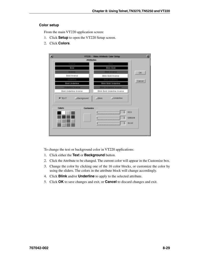
Chapter 8: Using Telnet, TN3270, TN5250 and VT220
707042-002 8-29
Color setup
From the main VT220 application screen:
1. Click Setup to open the VT220 Setup screen.
2. Click Colors.
To change the text or background color in VT220 applications:
1. Click either the Text or Background button.
2. Click the Attribute to be changed. The current color will appear in the Customize box.
3. Change the color by clicking one of the 16 color blocks, or customize the color byusing the sliders. The colors in the attribute block will change accordingly.
4. Click Blink and/or Underline to apply to the selected attribute.
5. Click OK to save changes and exit, or Cancel to discard changes and exit.

1783 Network Computing Terminal User’s Manual
707042-0028-30
Miscellaneous setup
From the main VT220 application screen:
1. Click Setup.
2. Click Miscellaneous. The VT220 Miscellaneous Setup screen is shown below:
• Emulation Type – Displays emulation type to be used (only VT220 currentlysupported)
• User Defined Terminal Type – Terminal type string sent to the host.
• ANSWERBACK – Enter the Answerback string.
• RESET Terminal – Select to reset the Emulator.
3. Click OK to save changes and exit, or Cancel to discard changes and exit.

Chapter 8: Using Telnet, TN3270, TN5250 and VT220
707042-002 8-31
Printer setup
From the main VT220 application screen:
1. Click Setup.
2. Click Printer.
3. Select Host Print or Screen Print.
Host Print
Select either Local or LPR printing. If using LPR, select the appropriate printer from thelist of configured LPR printers.

1783 Network Computing Terminal User’s Manual
707042-0028-32
Screen Print
• Printer Type – Specifies the printer driver to use when printing.• Lines per Inch – Specifies the number of Lines Per Inch to print.• Characters per Inch – Specifies the number of Characters Per Inch to print.• Lines per page – Specifies the number of Lines per Page to print. Selectable
range is 0-255.• Draft Quality – Prints draft quality when selected. Otherwise printing is
letter quality.• Attributes – If selected, prints intensified characters as bold and underlined
when required.• Portrait – If enabled, prints in Portrait mode. If disabled, prints in Landscape mode.• Mod 5 17 CPI – If selected, printing automatically changes to 17 CPI (characters
per inch) if the application screen is Mod 5.• Wide Paper – If enabled, allows printing of more than 80 characters per line.
This setting is generally used when Proprinter is selected as the Printer Type.• LPR Setup
• Enable LPR - Select to enable the VT220 client to send print jobs to a LPDnode such as a print server
• LPR Printer Window - Select the defined printer that will receive VT220print jobs. Once selected, the Local Name, Remote Name, and Remote Addresswill be displayed below the LPR Printer Window.
• Line Feed – Sends an immediate Line Feed to the selected printer.• Form Feed – Sends an immediate Form Feed to the selected printer
Chapter 9TN3270/TN5250 Keyboard Macros
In this Chapter...
Keystroke Record/Playback
Storing Keystroke Sequences
Playing Keystroke Sequences
Removing Keystroke Sequences
Advanced Feature Set: Pauses
Advanced Feature Set: Delays
Advanced Feature Set: Playback Speed
Special Notes

1783 Network Computing Terminal User’s Manual
707042-0029-2
Keystroke Record/Playback
The Keystroke Record/Playback function enables you to reduce the number of keystrokesrequired for a frequently repeated entry such as a logon sequences. Unique keystrokesequences can be stored for each of the 24 Function keys on the keyboard. The enteredkeystroke sequences are stored in nonvolatile memory, which means that the data is retainedeven if the power is turned off.
Note: There is a 7000 key limit on the length of each macro.
Storing Keystroke Sequences
1erugiF draobyekyek2210723NT
2erugiF draobyekyek4010723NT
3erugiF draobyekyek2210525NT
4erugiF draobyekyek4010525NT
Follow the steps below to store macros:
1. Press the Record key (See figures 1 - 4).
2. Press the F or PF key you wish to be associated with the macro. Any key other than anF or PF key will exit from macro record mode. If the key pressed to exit macro recordmode was anything other than Quit, there will be a beep to alert you of the (possiblyunintentional) cancellation.
3. Type the keys to be associate with the macro.
4. Press the Record key to save the macro and exit macro record mode. Press Quit keyto abandon the macro and exit record mode.
Caution: To avoid inadvertently recording over a macro, once you press the Record keyand then select the F or PF key to be associated with a macro, be sure to note the numberof keys already associated with the macro. This number will be displayed on the statusline. If there is no macro associated with F or PF, the number of keys will be displayed aszero. If you do not wish to record over this macro press the Quit key and you will exitrecord mode.

Chapter 9: TN3270/TN5250 Keyboard Macros
707042-002 9-3
Playing Keystroke Sequences
Follow the steps below to initiate macros:
1. Press the Play key (See figures 1 - 4).
2. Press the F or PF key associated with the macro you wish to recall. Any key other thanan F or PF key will exit from macro play mode. If the key pressed to exit macro playmode was anything other than Quit, there will be a beep to notify you of the (possiblyunintentional) cancellation.
3. The macro will be automatically recalled.
4. The macro will automatically terminate once all keys have been played. If you desire,the macro may be terminated at any point by pressing the Quit key.
Removing Keystroke Sequences
Follow the steps below to remove macros:
1. Press the Record key (See figures 1 - 4).
2. Press the F or PF key associated with the macro you wish to remove. Any key otherthan an F or PF key will exit from macro record mode. If the key pressed to exitmacro record mode was anything other than Quit, there will be a beep to notify you ofthe (possibly unintentional) cancellation.
3. Press the Record key to delete the macro and exit record mode. Press the Quit keyto abort and exit macro record mode with no changes made.
Advanced Feature Set: Pauses
There are certain key sequences, such as a logon password, that a user may wish to excludefrom a macro. At any point while recording a macro key sequence, the Pause key (seefigures 1 - 4) may be pressed to temporarily suspend record mode. The keystrokes fromthis point forward will not be recorded within the macro until macro record mode isresumed by pressing the Record key. The Quit key will abandon the macro, even whilemacro record is paused.
If the Pause key is pressed while in macro record mode, besides suspending recording,it will be embedded within the macro and cause the macro to pause automatically eachtime it is played back.
While playing back a macro the Pause key may be pressed to temporarily suspend themacro. At this point you may type in normal mode. Pressing the Play key will resume themacro. The Quit key will abandon the macro and return you to normal mode, even whilemacro play is paused.
Note: It is important to note that a Pause key may be embedded within a macro asmentioned in the paragraph above. If a macro pauses because of an embedded Pause key,a Play key is still required to resume the macro or a Quit key to terminate it. There is nokey combination that will permanently alter the functionality of a macro while in macroplay mode.

1783 Network Computing Terminal User’s Manual
707042-0029-4
Advanced Feature Set: Delays
Delays can be automatically introduced while in Input Inhibit mode. Input Inhibit(clock) will hold playback until released by host. Only Quit is permitted while theclock is displayed. If delays are desired at other times, the Delay key (see figures 1 -4) may be pressed while in macro record mode to embed an approximately one seconddelay within the macro. Multiple Delay keys may be combined to extend the lengthof the delay.
—————— Clock
Advanced Feature Set: Playback Speed
Follow the steps below to change the default playback speed:
1. Press the Speed key (see figures 1 - 4) while in normal mode.
2. Press the number associated with the new global playback speed. Valid numbers rangefrom “1”, slowest, to “9”, fastest. Any key other than a “1” through “9” will exit fromset playback speed mode. There will be a beep to notify you of the (possiblyunintentional) cancellation.
Macro playback speed can be varied on a macro by macro basis by embedding Speedkeys within the macro. These Speed keys do not change the default playback speed,only the current playback speed within the current emulator session.
The special speed “0” becomes valid while in macro record mode. The “0” speed changesthe speed back to the default speed. A Speed “0” is automatically embedded at both endsof a macro at the time it is created.
Playback speeds range between five and twenty-five characters per second with Speed“1” being the slowest and Speed “9” being the fastest.
Special Notes
To allow a macro to run in the background while you switch to another application, usethe Alt-Right Ctrl-Tab keys on the 122/104 key keyboard to prevent an accidental Quitkey from terminating macro modes. If the Alt-Right Ctrl-Tab keys are used, the emulatormacro modes will not be affected. Upon return to the emulator the macro modes will beexactly as they were before switching tasks.
When key sequences are added, deleted or edited, the file storage area is updated asnecessary to avoid gaps in the available storage area. There is a 7000 key limit on thelength of each macro.
Macros are independent of both keyboard and keyboard mapping. This allows stored keyfiles to be retrieved and sent to other 1783’s via FTP even if both machines do not use thesame style keyboard or special keyboard mappings are in place on one or both of themachines.
Sessions within the same emulator will use the same set of macros. They will playbackindependently, but if you record and save a macro in one session, that macro is changedfor all sessions.

Ch
apter 9: T
N3270/T
N5250 K
eybo
ard M
acros
707042-0029-5
PauseRecord
Play
Quit AltDelay/Speed
Left Control
Right Control
Macro Function Record Corresponds to Key: "ALT-Record"Macro Function Play Corresponds to Key: "Play"Macro Function Pause Corresponds to Key: "Pause"Macro Function Quit Corresponds to Key: "ALT-Quit"Macro Function Delay Corresponds to Key: "ALT-Speed"F1, F2...F24 Correspond to Keys: "F1", "F2"... "F24"
Figure 1. 3270 122-Key Keyboard

1783 Netw
ork C
om
pu
ting
Termin
al User’s M
anu
al
707042-0029-6
Record Play Pause/QuitDelay Speed
AltShiftLeft Control Right Control
Macro Function Record Corresponds to Key: "ALT-Record"Macro Function Play Corresponds to Key: "ALT-Play"Macro Function Pause Corresponds to Key: "SHIFT-Pause"Macro Function Quit Corresponds to Key: "ALT-Quit"Macro Function Delay Corresponds to Key: "ALT-Delay"Macro Functions F1, F2...F12 Correspond to Keys: "F1", "F2"..."F12"Macro Function Speed Corresponds to Key: "ALT-Speed"F12, F13...F24 Correspond to Keys: "SHIFT-F1", "SHIFT-F2"...SHIFT-F12"
Figure 2. 3270 101/104-Key Keyboard
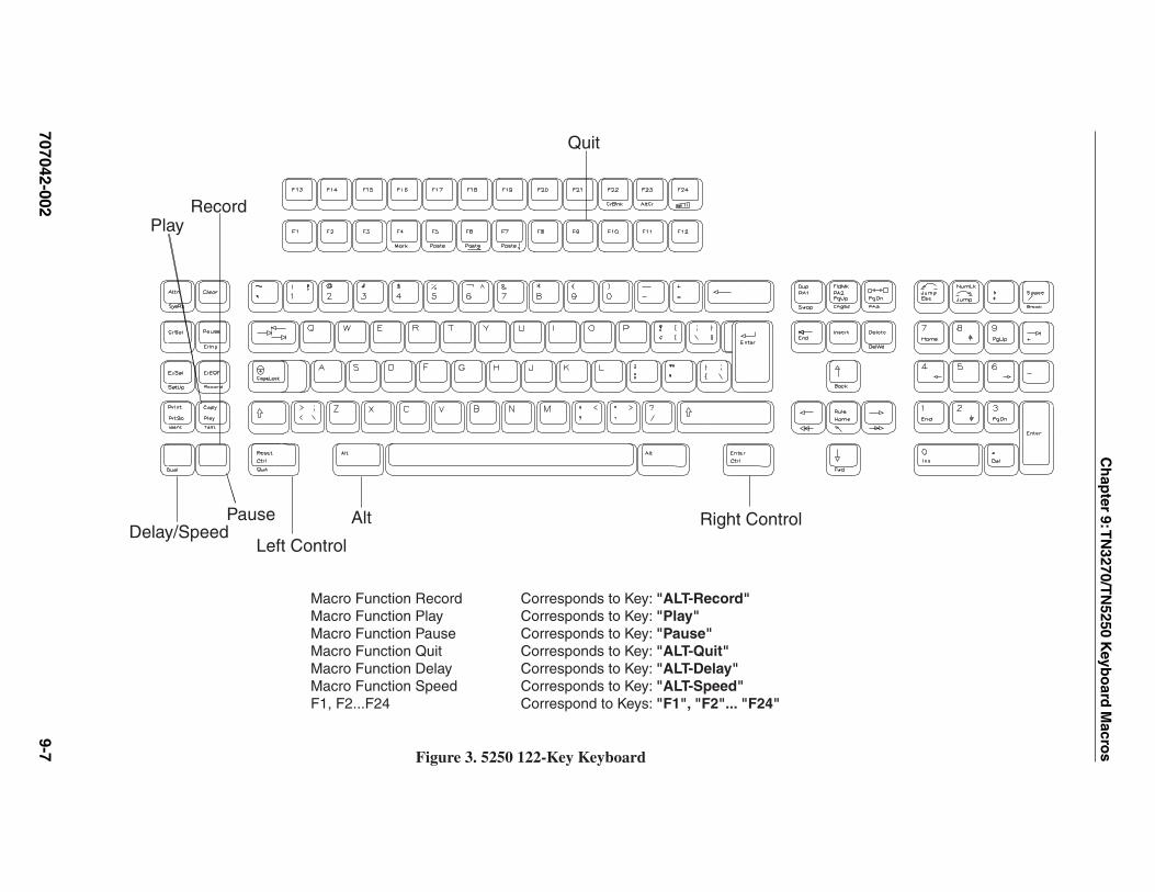
Ch
apter 9: T
N3270/T
N5250 K
eybo
ard M
acros
707042-0029-7
Pause
RecordPlay
Quit
AltDelay/Speed
Left Control
Right Control
Macro Function Record Corresponds to Key: "ALT-Record"Macro Function Play Corresponds to Key: "Play"Macro Function Pause Corresponds to Key: "Pause"Macro Function Quit Corresponds to Key: "ALT-Quit"Macro Function Delay Corresponds to Key: "ALT-Delay"Macro Function Speed Corresponds to Key: "ALT-Speed"F1, F2...F24 Correspond to Keys: "F1", "F2"... "F24"
Figure 3. 5250 122-Key Keyboard

1783 Netw
ork C
om
pu
ting
Termin
al User’s M
anu
al
707042-0029-8 Record Play Pause QuitDelay Speed
AltShiftLeft Control Right Control
Macro Function Record Corresponds to Key: "ALT-Record"Macro Function Play Corresponds to Key: "ALT-Play"Macro Function Pause Corresponds to Key: "SHIFT-Pause"Macro Function Quit Corresponds to Key: "ALT-Quit"Macro Function Delay Corresponds to Key: "ALT-Delay"Macro Functions F1, F2...F12 Correspond to Keys: "F1", "F2"..."F12"Macro Function Speed Corresponds to Key: "ALT-Speed"F12, F13...F24 Correspond to Keys: "SHIFT-F1", "SHIFT-F2"..."SHIFT-F12"
Figure 4. 5250 101/104-Key Keyboard
Chapter 10Accessing your intranet and the Internet
In this Chapter...
Configuring Voyager Browser
Basic browsing
Using hotlists
Printing

1783 Network Computing Terminal User’s Manual
707042-00210-2
The 1783 NCT allows connecting to the Internet in four different ways: via Coax, Ethernet,Token Ring, and the Serial Port. Your system administrator will have taken care of thephysical connection when installing the network terminal.
The Voyager browser is a lightweight Web browser optimized for non-PC devices. Voyagercan help manage access to your organization’s intranet as well as to the Internet.
Configuring Voyager Browser
In Voyager, you can configure parameters such as:
• Memory caching
• General information, such as your home page
• Font and color display
To access the configuration screens for Voyager browser:
1. Click the button in the lower-left corner of the screen.
2. Select Voyager from the application menu. The Voyager browser window will open:
3. Click Edit on Voyager’s Toolbar menu.
4. Click Configuration. The WWW Configuration dialog box will appear.

Chapter 10: Accessing your Intranet and the Internet
707042-002 10-3
Cache tab
• Enable Disk Cache – Allows internet pages to be stored in the cache for fasterretrieval.
• Disk Cache Size – Specify the amount of space used for the disk cache.
• Clear main cache on exit – The disk cache will be cleared each time Voyager isclosed.
• Clear Memory Cache – Clears the memory cache immediately.
• Cache File Location – This field is informational only and cannot be changed.
• Cache Verify Policy– Never - Voyager never verifies the web page in the cache with the Internet; it
always retrieves the page from the cache.– Always - Voyager always downloads the web page from the Internet, even if it is
already stored in the cache.– Once per session - Voyager will check once during each session to see if a
web page on the Internet has changed from the page stored in the cache.
Note: Voyager does not update the files on your network (that is, if you typed file in the Siteinput field instead of http). If a file has been changed, click Reload to see the updated version.
• Number of pages to cache – Specify the number of pages to store in the memorycache. The default is 2. Voyager will run faster if a large number of web pages arecached; however, increasing the number of cached pages will use more memory.

1783 Network Computing Terminal User’s Manual
707042-00210-4
• Image Cache size – Specify the maximum cache size for images that are to be heldin the cache. The default is 1024KB for full; 512KB for compact. Recommendedsizes are:– 512KB for a memory-constrained environment– 1024KB for 256 Color– 2048KB for High Color or True Color
The image cache holds all images rendered to the screen. If web pages are loading withimages not displayed, or you have a high-color monitor graphics driver running and the“Use 256 colors only” button is disabled, the image cache size may need to be increased.
Note: The cache file directory is cleared when Voyager Browser is closed. Your systemadministrator can advise you on setting these options.
User Info tab
• Home Page – Enter the complete URL of the web page to be loaded each timeVoyager is started. This field may also be left blank to avoid loading any page. Voyagermust be restarted for the change to become effective.
• Email Address – Enter your e-mail address.
• Email Server – Enter the IP address of your SMTP server – for example,quics.qnx.com or 10.0.0.222.
• Underline links – Enable if the links on web pages should be underlined.
• Display server errors – Enable if error pages should be generated by the hostserver.
• Use 256 colors only – Display web graphics using 256 colors only (instead of HighColor or True Color).
• Auto Load Images – Select to automatically load and display HTML images on agiven page.

Chapter 10: Accessing your Intranet and the Internet
707042-002 10-5
Connection tab
Use the Connection tab to set up network addresses needed by Voyager:
• Use Proxy Server – Enable if a proxy server is used for HTTP, FTP Gopher, or if aSOCKS host is used to connect to the Internet. Enter the IP address of the proxyserver(s) in the appropriate field. Enter the port number in the adjacent field.
• Max Connections – Enter the maximum number of connections to the Internetallowed at one time.
• Proxy Overrides – Enter the addresses of computers that should not go through theproxy server(s). The wildcard character “ * ” may also be used in the override field.
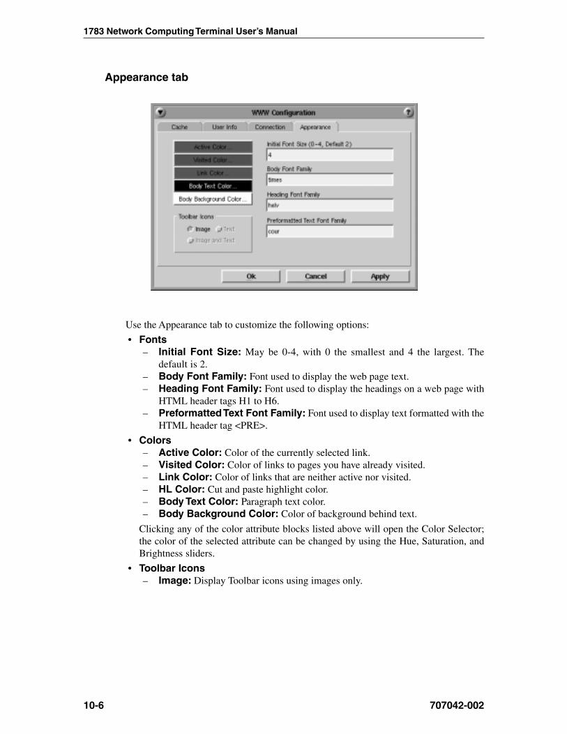
1783 Network Computing Terminal User’s Manual
707042-00210-6
Appearance tab
Use the Appearance tab to customize the following options:
• Fonts– Initial Font Size: May be 0-4, with 0 the smallest and 4 the largest. The
default is 2.– Body Font Family: Font used to display the web page text.– Heading Font Family: Font used to display the headings on a web page with
HTML header tags H1 to H6.– Preformatted Text Font Family: Font used to display text formatted with the
HTML header tag <PRE>.
• Colors– Active Color: Color of the currently selected link.– Visited Color: Color of links to pages you have already visited.– Link Color: Color of links that are neither active nor visited.– HL Color: Cut and paste highlight color.– Body Text Color: Paragraph text color.– Body Background Color: Color of background behind text.
Clicking any of the color attribute blocks listed above will open the Color Selector;the color of the selected attribute can be changed by using the Hue, Saturation, andBrightness sliders.
• Toolbar Icons– Image: Display Toolbar icons using images only.
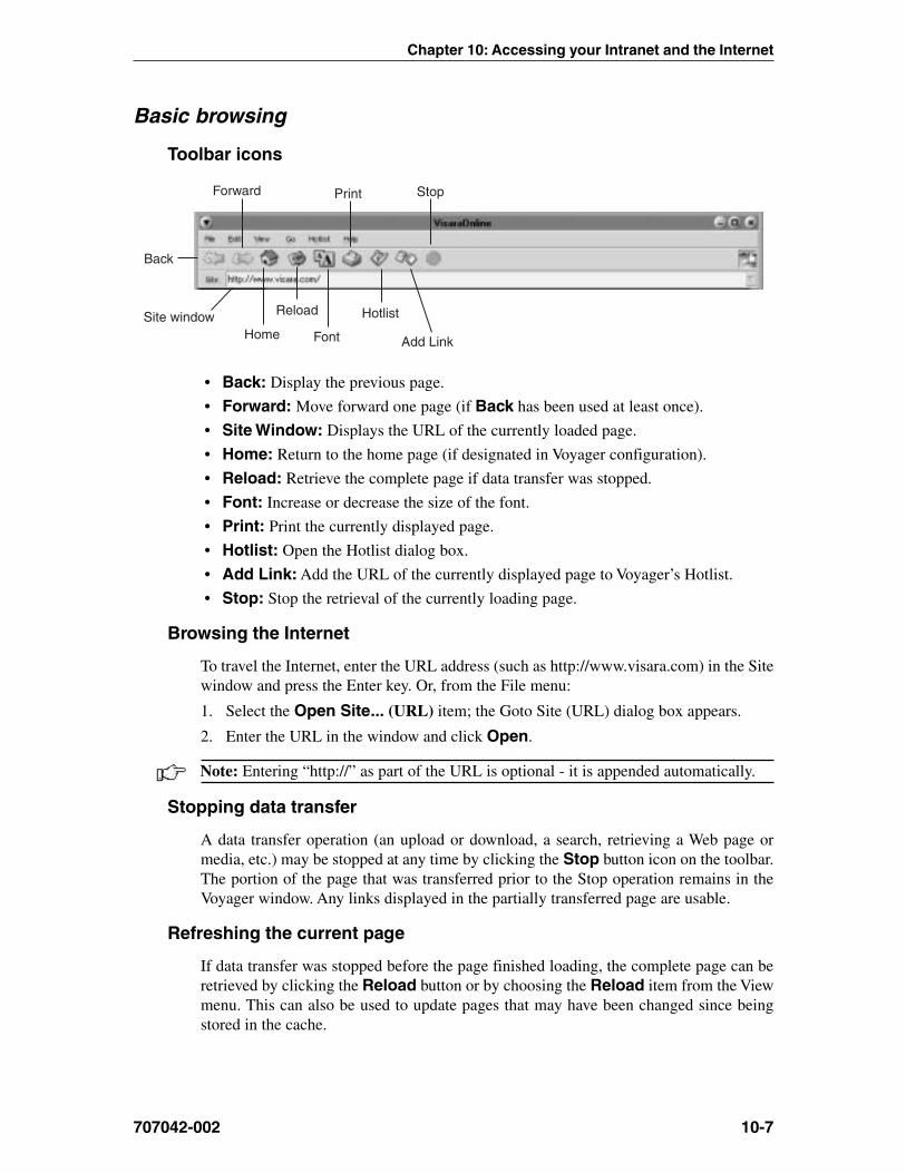
Chapter 10: Accessing your Intranet and the Internet
707042-002 10-7
Basic browsing
Toolbar icons
Back
Forward
Home
Reload
Font
Hotlist
Add Link
Stop
Site window
• Back: Display the previous page.
• Forward: Move forward one page (if Back has been used at least once).
• Site Window: Displays the URL of the currently loaded page.
• Home: Return to the home page (if designated in Voyager configuration).
• Reload: Retrieve the complete page if data transfer was stopped.
• Font: Increase or decrease the size of the font.
• Print: Print the currently displayed page.
• Hotlist: Open the Hotlist dialog box.
• Add Link: Add the URL of the currently displayed page to Voyager’s Hotlist.
• Stop: Stop the retrieval of the currently loading page.
Browsing the Internet
To travel the Internet, enter the URL address (such as http://www.visara.com) in the Sitewindow and press the Enter key. Or, from the File menu:
1. Select the Open Site... (URL) item; the Goto Site (URL) dialog box appears.
2. Enter the URL in the window and click Open.
Note: Entering “http://” as part of the URL is optional - it is appended automatically.
Stopping data transfer
A data transfer operation (an upload or download, a search, retrieving a Web page ormedia, etc.) may be stopped at any time by clicking the Stop button icon on the toolbar.The portion of the page that was transferred prior to the Stop operation remains in theVoyager window. Any links displayed in the partially transferred page are usable.
Refreshing the current page
If data transfer was stopped before the page finished loading, the complete page can beretrieved by clicking the Reload button or by choosing the Reload item from the Viewmenu. This can also be used to update pages that may have been changed since beingstored in the cache.

1783 Network Computing Terminal User’s Manual
707042-00210-8
Going backward and forward
The Back button on the toolbar displays the previous document; click the Forwardbutton to move forward one page (only if the Back button has been used at least once).Back and Forward can also be selected from the Go menu.
Returning to your home page
To return to your home page at any time, click the Home button on the toolbar or chooseHome from the Go menu.
Finding text
To find specific text:
1. Open the Search dialog box by choosing Find in Document from the Edit menu.
2. Type the text that you want to find in the Search For: window.
3. If required, you can toggle the option boxes to:
• start the search at the top of the page• search backwards• turn off text case-sensitivity
4. Click Find. To search for additional instances of the same text, click Find Again.
Changing the size of the font
The font size may be increased and decreased by clicking the Font button on the toolbar.Clicking this button repeatedly will toggle through the 5 available font sizes. The font sizemay also be changed by selecting Increase Font or Decrease Font from the View menu.
Viewing history
Voyager keeps a running list of places that were visited during your sessions. To revisitone of those sites, choose History List from the Go menu. Double click the title of thesite that should be reopened.
Using hotlists
Hotlists
Use the Hotlist to keep track of your favorite sites and to go to a site without typingits URL. When a link is added to Voyager’s Hotlist, the title and URL of the site willbe saved.
Adding sites to Hotlist
To add a shortcut for the current page click on the Add Link icon on the toolbar or:
1. Open the Hotlist dialog box by selecting Hotlist from Voyager’s toolbar menu.
2. From the dropdown menu, click Add to Hotlist. The item will be added to theHotlist screen and will also be available from the Hotlist dropdown menu.
Note: The Hotlist uses Flash file space that may be in limited supply.

Chapter 10: Accessing your Intranet and the Internet
707042-002 10-9
Viewing hotlists
To go to a site that has been added to the Hotlist, click the Hotlist button on the Toolbarmenu and select the site from the dropdown menu. The site may also be selected from theHotlist dialog box as follows:
1. Select Hotlist from the Toolbar menu.
2. Click Edit Hotlist... The Hotlist dialog box will be displayed:
3. Double-click the title of the site that you wish to visit, or click Load Link fromHotlist’s View menu.
Deleting sites from the hotlist
To delete site addresses that are no longer required:
1. Open the Hotlist dialog box.
2. Select the line to be deleted.
3. Click the Delete key or select Delete from Hotlist’s Edit menu.
Printing
The currently displayed Web page can be printed by clicking the Print button on thetoolbar or by selecting Print from the File menu. Printer Setup can also be accessedfrom the File menu.


Chapter 11Using personal productivity tools
In this Chapter...
NCT Mail
Message Pad
DayMinder
Calculator
Snapshot
Dial-up connection

1783 Network Computing Terminal User’s Manual
707042-00211-2
NCT Mail
1783 NCT Mail provides an easy-to-use way to send and receive e-mail (electronic mail).
Starting NCT Mail
Start NCT Mail by performing the following actions:
1. Click the button (located at the lower left-hand corner of the screen).
2. Select Email from the application menu. If password protection was not selectedduring configuration, the NCT Mail window will open.
Note: If NCT Mail was not configured by your system administrator prior to opening theapplication for the first time, a configuration screen will appear. See Chapter 11:Configuring NCT Mail for configuration details.
If password protection was selected during configuration, the screen shown belowwill appear.
1. Enter your password in the dialog box.
2. Press Enter on the keyboard. The NCT Mail window will appear.
Note: To setup or change the password, see Chapter 11: Configuring NCT Mail.

Chapter 11: Using personal productivity tools
707042-002 11-3
Checking for - and reading - your mail
To check for mail addressed to you, click the Check Mail button in the 1783 NCT Mailmenu bar at the bottom of the screen or select Check Mail from the Operations menu.
A list of incoming mail messages will be presented in the top part of the display, with thename of the sender, the subject, and the size of the message.
To read a message
Double-click anywhere on the message information. The sender’s message will bedisplayed in the Message Area. The header information may be displayed by resizing thearea between the 2 horizontal bars above the message area.
Replying to and forwarding mail
With the message you wish to reply to displayed in the message area, click the Replybutton at the bottom of the window. Follow the directions for sending new mail (page9-4) to reply to a received message.
To forward a message you have received:
1. Click the Forward button.
2. Fill in the address of the person to whom you are forwarding the message.
3. Click Send.

1783 Network Computing Terminal User’s Manual
707042-00211-4
Sending new mail1. Click the New Mail button at the bottom of the window. The Compose Mail screen
will appear:
2. Fill in the address fields. Enter the e-mail address of a recipient by typing the addressin the To: field. Separate two or more addresses by using a comma between theaddresses.• To: – Sends message to one or more recipients.• Cc: – Optional. Sends a copy to this (these) address(es). The people receiving
copies will be listed in the Message Header Area.• Bcc: – Optional. Sends a “blind” copy to this (these) address(es). The people
receiving copies will not be listed in the Message Header Area.
Note: If you are replying, the To: address field is automatically filled.
3. Fill in the subject title.
4. Enter a message in the space provided.
5. Click Send.
To exit NCT Mail, select Exit from the File dropdown menu.

Chapter 11: Using personal productivity tools
707042-002 11-5
Message Pad
The 1783 NCT includes a handy “sticky note” utility that lets you post a to-do list or free-form text message on your workspace. The capacity of the Message Pad is 4096 characters.Characters are of a fixed font and can be inserted and deleted. When Message Pad isclosed the note is saved and will appear in the message area the next time Message Pad isopened. The Message Pad window can be sized and moved the same as other windows.
Posting a note to yourself
To post a note on your workspace:
1. Click the button (located at the lower left-hand corner of the screen) to open theapplication menu.
2. Click Message Pad. The following screen will appear:
3. Click in the Message area and type your message.
4. To close the Message Pad, click its menu button (top left), and select Close from thedropdown menu.

1783 Network Computing Terminal User’s Manual
707042-00211-6
DayMinder
What is DayMinder?
DayMinder provides a simple, graphical way to organize your daily schedule and activities.With DayMinder, you can schedule appointments, plan meetings, track your tasks, andmaintain your address book.
Starting DayMinder1. Click the button (located at the lower left-hand corner of the screen) to open the
application menu.
2. Click DayMinder.
DayMinder at a glance
A typical DayMinder session may look like this:
DayminderButton bar
MonthlyCalendar
WeeklyPlanner
Menu bar Appointment Button bar
AppointmentPanel
RemindersPanel
ToDoPanel
The DayMinder window provides the following:
• DayMinder button bar – Offers the following shortcuts:
GoTo Today
Address Book
Group Planner
• Menu Bar – Perform most major functions, from creating appointments and tasks tosetting application preferences.
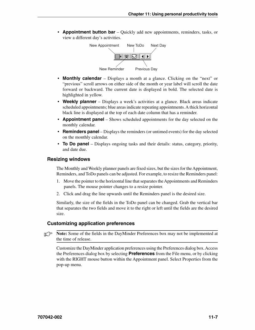
Chapter 11: Using personal productivity tools
707042-002 11-7
• Appointment button bar – Quickly add new appointments, reminders, tasks, orview a different day’s activities.
New Appointment New ToDo Next Day
New Reminder Previous Day
• Monthly calendar – Displays a month at a glance. Clicking on the “next” or“previous” scroll arrows on either side of the month or year label will scroll the dateforward or backward. The current date is displayed in bold. The selected date ishighlighted in yellow.
• Weekly planner – Displays a week’s activities at a glance. Black areas indicatescheduled appointments; blue areas indicate repeating appointments. A thick horizontalblack line is displayed at the top of each date column that has a reminder.
• Appointment panel – Shows scheduled appointments for the day selected on themonthly calendar.
• Reminders panel – Displays the reminders (or untimed events) for the day selectedon the monthly calendar.
• To Do panel – Displays ongoing tasks and their details: status, category, priority,and date due.
Resizing windows
The Monthly and Weekly planner panels are fixed sizes, but the sizes for the Appointment,Reminders, and ToDo panels can be adjusted. For example, to resize the Reminders panel:
1. Move the pointer to the horizontal line that separates the Appointments and Reminderspanels. The mouse pointer changes to a resize pointer.
2. Click and drag the line upwards until the Reminders panel is the desired size.
Similarly, the size of the fields in the ToDo panel can be changed. Grab the vertical barthat separates the two fields and move it to the right or left until the fields are the desiredsize.
Customizing application preferences
Note: Some of the fields in the DayMinder Preferences box may not be implemented atthe time of release.
Customize the DayMinder application preferences using the Preferences dialog box. Accessthe Preferences dialog box by selecting Preferences from the File menu, or by clickingwith the RIGHT mouse button within the Appointment panel. Select Properties from thepop-up menu.

1783 Network Computing Terminal User’s Manual
707042-00211-8
Types of scheduled activities• Appointments – Scheduled events with a specified date and time. A meeting is a
good example because it is planned for a specified time on a specified day.
• Reminders – Untimed events with a specified date but no associated time, such as abirthday or anniversary.
• To Do – Events or tasks that are defined over a period of time by a starting and anending date. An example of a task could be the writing and distributing of the minutesof a meeting, because the writing of the minutes occurs over a period of time and hasa due date.
Adding appointments
Adding an appointment to DayMinder is easy:
1. In the Monthly Calendar panel, click the next or previous month scroll arrows untilthe appropriate calendar for the month and year is displayed. Click on the desiredday. DayMinder highlights the selection in the Weekly planner.
2. In the Appointments panel, select the desired block of time for your appointment. Forexample, if your appointment is scheduled from 2 p.m. to 3 p.m. on Friday, November29, select the period by clicking the 2 p.m. start time on Friday, November 29, anddragging to the 3 p.m. end time. The same procedure may be followed to select ablock of time from the Weekly Planner panel. The selected block of time is indicatedon the left side of the Appointments panel beside the time and by a box in the Weeklyplanner.
3. The details of the appointment are entered in the Appointment dialog box. The dialogbox can be displayed using any one of the following methods:• Click the New Appointment button on the Appointment button bar.• Move the mouse pointer into the Appointments panel, click the RIGHT mouse
button, and then select the New Appt. item from the pop-up menu.• From the Edit menu, select the New Appt... item.
Chapter 11: Using personal productivity tools
707042-002 11-9
You can change or add the:
• Date – Use the up or down arrows or the month icon to select or change the date.
• Time – Nudge the time in 5-minute intervals using the up and down arrows.
• Description – Click in the box below the time to enter the appropriate descriptionand information about the appointment.
• Repetition – If the appointment occurs on a repeating basis, select the frequency andDayMinder will automatically make the entry for each occurrence.
To save the changes, click OK. To leave the dialog box without saving changes,click Cancel.
Adding reminders
Adding a Reminder to DayMinder is like adding an appointment, but in the case of areminder, there is no specific time assigned.
To create a Reminder do one of the following:
• Select the New Reminder button from the Appointment button bar.
• Move the mouse pointer into the Appointments or Reminders panel, click the RIGHTmouse button, and select the New Reminder item.
• From the Edit menu, select the New Reminder... item. The Appointment dialog boxappears with the Reminder toggle “lit.”
Enter the date and the description of the reminder and click OK.
Note: An appointment can be changed into a reminder (or a reminder into an appointment)by toggling the Reminder button in the appointment panel.
Adding a task to the ToDo listTo create a task do one of the following:
• Select the New ToDo button from the Appointment button bar.
• Move the mouse pointer into the Appointments or ToDo panel, click the RIGHT mousebutton, and select the New ToDo item from the pop-up list.
• From the Edit menu, select the New ToDo... item.
Here you can specify the following:
• Priority – The importance of the task may be selected by choosing a number between1 and 5 inclusive. Priority 1 is more important than priority 5. The default is 3.
• Category – Tasks can be categorized by type. Use the up arrow to select the requiredtask type (the default is All). New categories can be created by selecting the NewCategory button.
• Description – A description of the task.
• Notes – A field for any other pertinent information. Notes are displayed only whenthe task is edited.
• Begin Date – The start date of the task. Select the date by clicking the up or downarrows or by clicking the month icon and selecting the desired date.

1783 Network Computing Terminal User’s Manual
707042-00211-10
• End Date – The planned end date of the task. Select the date by clicking the up ordown arrows or by clicking the month icon and selecting the required date.
To save the changes, click OK. To leave the dialog box without saving changes, clickCancel.
Editing and deleting scheduled activities
Appointments, Reminders, and ToDo activities may be edited or deleted; an appointmentmay also be copied. To edit a scheduled activity do one of the following:
• Move the pointer on top of the activity or event and click the RIGHT mouse button. Apop-up window appears with the available commands.
• Select the appropriate editing command from the Edit item on the main menu (copy,cut, delete, edit, paste).
Address Book
Note: Some features in the Address Book may not be implemented at the time of release.
You can keep track of friends and colleagues in the Address Book. To open the AddressBook, click the Address Book icon in the DayMinder button bar.
• Address Book – Make entries for both private and business addresses.
• Sort by – Determines how to sort the entries in the book. The default is by last name.
• Alphabet Buttons – Quickly find entries by selecting the first letter. If no entriesexist for a specified letter, the first entry under the next letter is displayed.
• OK – Saves the current entry and exits the Address Book. By default, the AddressBook always saves the information on the screen when you move to another entry.
• New – Brings up a blank address form.
• Delete – Deletes the current screen entry.
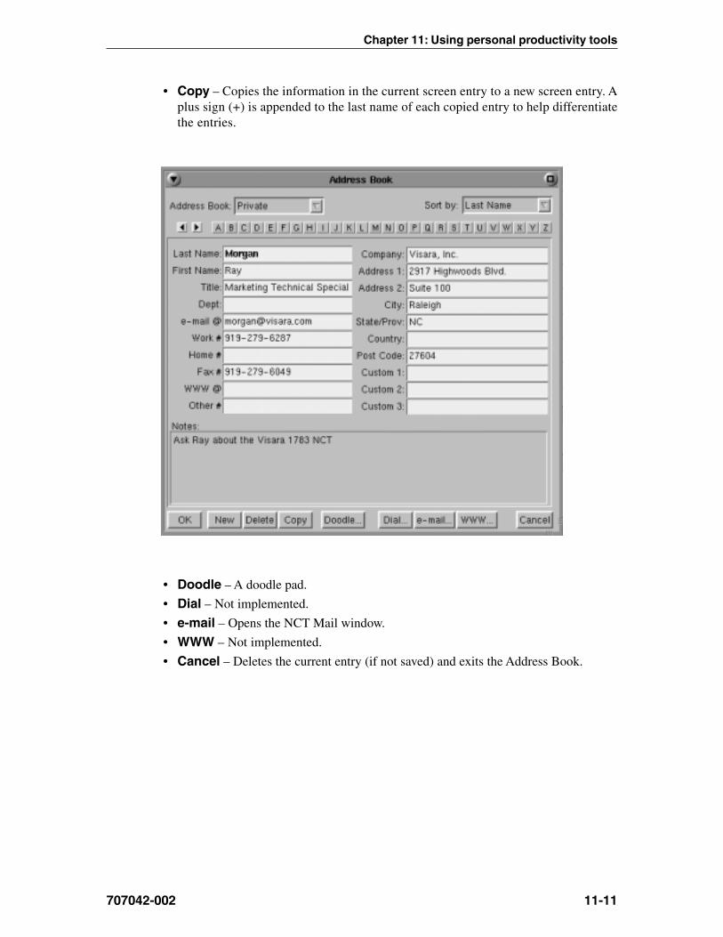
Chapter 11: Using personal productivity tools
707042-002 11-11
• Copy – Copies the information in the current screen entry to a new screen entry. Aplus sign (+) is appended to the last name of each copied entry to help differentiatethe entries.
• Doodle – A doodle pad.
• Dial – Not implemented.
• e-mail – Opens the NCT Mail window.
• WWW – Not implemented.
• Cancel – Deletes the current entry (if not saved) and exits the Address Book.
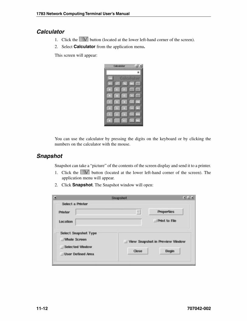
1783 Network Computing Terminal User’s Manual
707042-00211-12
Calculator1. Click the button (located at the lower left-hand corner of the screen).
2. Select Calculator from the application menu.
This screen will appear:
You can use the calculator by pressing the digits on the keyboard or by clicking thenumbers on the calculator with the mouse.
Snapshot
Snapshot can take a “picture” of the contents of the screen display and send it to a printer.
1. Click the button (located at the lower left-hand corner of the screen). Theapplication menu will appear.
2. Click Snapshot. The Snapshot window will open:
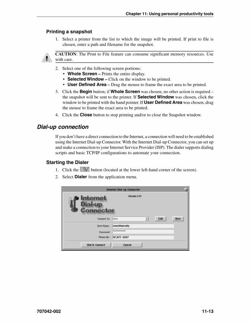
Chapter 11: Using personal productivity tools
707042-002 11-13
Printing a snapshot1. Select a printer from the list to which the image will be printed. If print to file is
chosen, enter a path and filename for the snapshot.
CAUTION: The Print to File feature can consume significant memory resources. Usewith care.
2. Select one of the following screen portions:• Whole Screen – Prints the entire display.• Selected Window – Click on the window to be printed.• User Defined Area – Drag the mouse to frame the exact area to be printed.
3. Click the Begin button; if Whole Screen was chosen, no other action is required –the snapshot will be sent to the printer. If Selected Window was chosen, click thewindow to be printed with the hand pointer. If User Defined Area was chosen, dragthe mouse to frame the exact area to be printed.
4. Click the Close button to stop printing and/or to close the Snapshot window.
Dial-up connection
If you don’t have a direct connection to the Internet, a connection will need to be establishedusing the Internet Dial-up Connector. With the Internet Dial-up Connector, you can set upand make a connection to your Internet Service Provider (ISP). The dialer supports dialingscripts and basic TCP/IP configurations to automate your connection.
Starting the Dialer1. Click the button (located at the lower left-hand corner of the screen).
2. Select Dialer from the application menu.
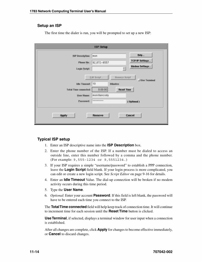
1783 Network Computing Terminal User’s Manual
707042-00211-14
Setup an ISP
The first time the dialer is run, you will be prompted to set up a new ISP:
Typical ISP setup1. Enter an ISP descriptive name into the ISP Description box.
2. Enter the phone number of the ISP. If a number must be dialed to access anoutside line, enter this number followed by a comma and the phone number.(For example: 9,555-1234 or 9,5551234.)
3. If your ISP requires a simple “username/password” to establish a PPP connection,leave the Login Script field blank. If your login process is more complicated, youcan edit or create a new login script. See Script Editor on page 9-16 for details.
4. Enter an Idle Timeout Value. The dial-up connection will be broken if no modemactivity occurs during this time period.
5. Type the User Name.
6. Optional: Enter your account Password. If this field is left blank, the password willhave to be entered each time you connect to the ISP.
The Total Time connected field will help keep track of connection time. It will continueto increment time for each session until the Reset Time button is clicked.
Use Terminal, if selected, displays a terminal window for user input when a connectionis established.
After all changes are complete, click Apply for changes to become effective immediately,or Cancel to discard changes.

Chapter 11: Using personal productivity tools
707042-002 11-15
Advanced ISP setup
The typical ISP setup just described should work in most cases. If you can not make aconnection using the typical ISP setup, you may need to provide some additionalcustomizations like TCP/IP settings and creating a login script.
TCP/IP settings• ISP Address – This is the IP address of your ISP. This is usually assigned
automatically upon connection to the ISP. If your ISP tells you to specify this address,type the value here. Example: 255.255.252.1
• Your Address – This is your IP address. Most ISP providers will dynamically allocateone when a connection is made. If you have a fixed IP address that never changes,then it should be entered here. Example: 255.255.252.1.
Modem settings
The Initialization String and Baud Rate may be changed if necessary. The InitializationString is ATZ by default.
CAUTION: Do not change the device (port) field. Changing this field will render theserial port inoperable.
Login script
The dialer has a built-in login script that will do the following:
1. Wait for a login prompt from the ISP and then issue your username.
2. Wait for a password prompt from the ISP and then issue your password.
3. Run pppd.
To use this default script, leave the Login Script field in ISP Setup blank.
If your login process deviates from the above procedure, you’ll need to create a new loginscript. Suppose your ISP has a two-level login process; you could create a login scriptthat looks like this:
:roftiaW :htiwylpeR :sutatS
*nigol* resuppp ...detcennoC
*drowssap* yzzyx
*nigol* RESU$ ...nigniggoL
*drowssap* DROWSSAP$

1783 Network Computing Terminal User’s Manual
707042-00211-16
Script Editor
To create a new login script
1. Start the Dialer.
2. Click New. The ISP Setup dialog box will open.
3. Follow the procedures detailed in Setup An ISP.
4. Enter a name for the new script in the Login Script field.
5. Click Edit Script... to open Script Editor.
6. Create or edit the script using the elements, patterns and special character sequencesdescribed in the following sections.
To edit a row
1. Click the row in the script that is to be changed.
2. Tab to a field in the row at the bottom of Script Editor and type in the change.
3. Click Modify. Otherwise the changes to a row won’t be saved.
To add a row to the script
1. Click a row in the script that is either before or after the position where the new rowshould be inserted.
2. Enter the script in the fields at the bottom of Script Editor.
3. Click either Insert Before or Insert After; the row will be added to the script.
Click Done when the script is completed. This creates a login script file.
Login script elements:
tpircsnigoLtnemele
noitpircseD
roFtiaW
htiwhctamasierehtlitnutsohetomerehtmorfsretcarahcseviecerrelaidehThctamnfnoitcnufXISOPehtsesurelaidehT.yrtneroFtiaWehtninrettapeht
.hctamehtodot)ETOUQ_MNF,enil,nrettap(atahttpecxe,snrettapemanelifs'llehsehtotralimissisnrettaprofxatnysehThctamlliw**\*,elpmaxeoF.retcarahcyranidronasadetaertsihsalsdrawrof
ees,sretcarahclaicepsfotsilaroF.ksiretsanagniniatnocsretcarahcfoenilyna.71-9egapnonoitcessnrettaPehtnielbatsretcarahclaicepSeht
dna"NIGOL"tahtsnaemhcihwesacrewolnienoderaskcehcroFtiaWllA.hctamlliw"nigol"
eht,tpircsafoeniltsrifehtnidesusihsalskcabelgnisafognitsisnocnrettapafI.tsohetomerehtmorfsretcarahcrofgnitiawtuohtiwsdeecorprelaid
htiWylpeR
niylperehtstimerelaideht,yrtneroFtiaWehtrofhctamasahrelaidehtnehW.tsohetomerehtotyrtnehtiWylpeReht
roF.hsalskcabahtiwsdneylperehtsselnuretcarahcRCastimenehtrelaidehTnielbatecneuqeSretcarahClaicepSehtees,secneuqesretcarahclaicepsrehto
.71-9egapnonoitcesylpeRehT
sutatSnigolehtgnirudegatsagnitcelferegassemsutatsaesopmoc,dleifsihtnI
.wodniwsutatsrelaidehtnideyalpsiderasegassemsutatS.ssecorp
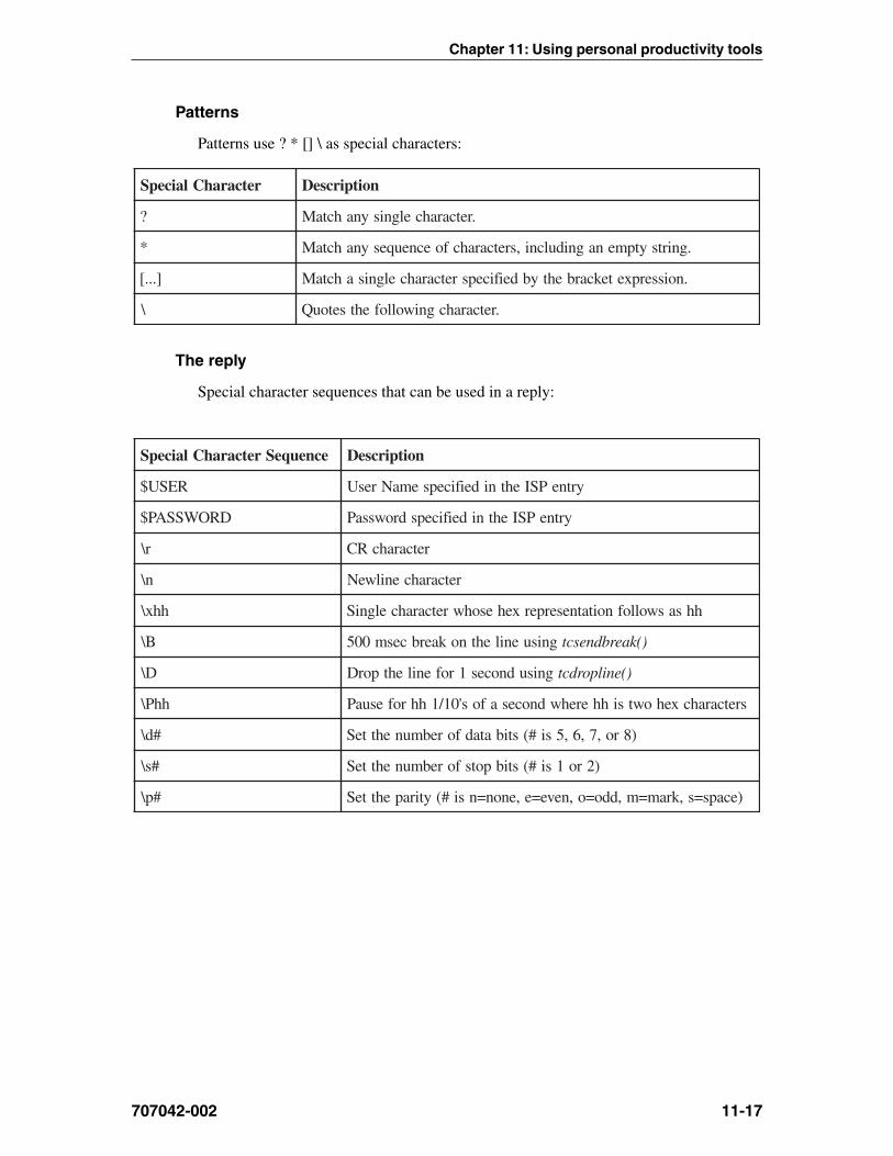
Chapter 11: Using personal productivity tools
707042-002 11-17
Patterns
Patterns use ? * [] \ as special characters:
retcarahClaicepS noitpircseD
? .retcarahcelgnisynahctaM
* .gnirtsytpmenagnidulcni,sretcarahcfoecneuqesynahctaM
]...[ .noisserpxetekcarbehtybdeificepsretcarahcelgnisahctaM
\ .retcarahcgniwollofehtsetouQ
The reply
Special character sequences that can be used in a reply:
ecneuqeSretcarahClaicepS noitpircseD
RESU$ yrtnePSIehtnideificepsemaNresU
DROWSSAP$ yrtnePSIehtnideificepsdrowssaP
r\ retcarahcRC
n\ retcarahcenilweN
hhx\ hhsaswollofnoitatneserperxehesohwretcarahcelgniS
B\ gnisuenilehtnokaerbcesm005 )(kaerbdnesct
D\ gnisudnoces1rofenilehtporD )(enilpordct
hhP\ sretcarahcxehowtsihherehwdnocesafos'01/1hhrofesuaP
#d\ )8ro,7,6,5si#(stibatadforebmunehtteS
#s\ )2ro1si#(stibpotsforebmunehtteS
#p\ )ecaps=s,kram=m,ddo=o,neve=e,enon=nsi#(ytirapehtteS


Chapter 12Safety, Power, and Environmental Requirements
In this Chapter...
Space planning: physical statistics
Meeting environmental requirements
Power cable requirements
Power outlet requirements
Electrical interference and atmospheric considerations
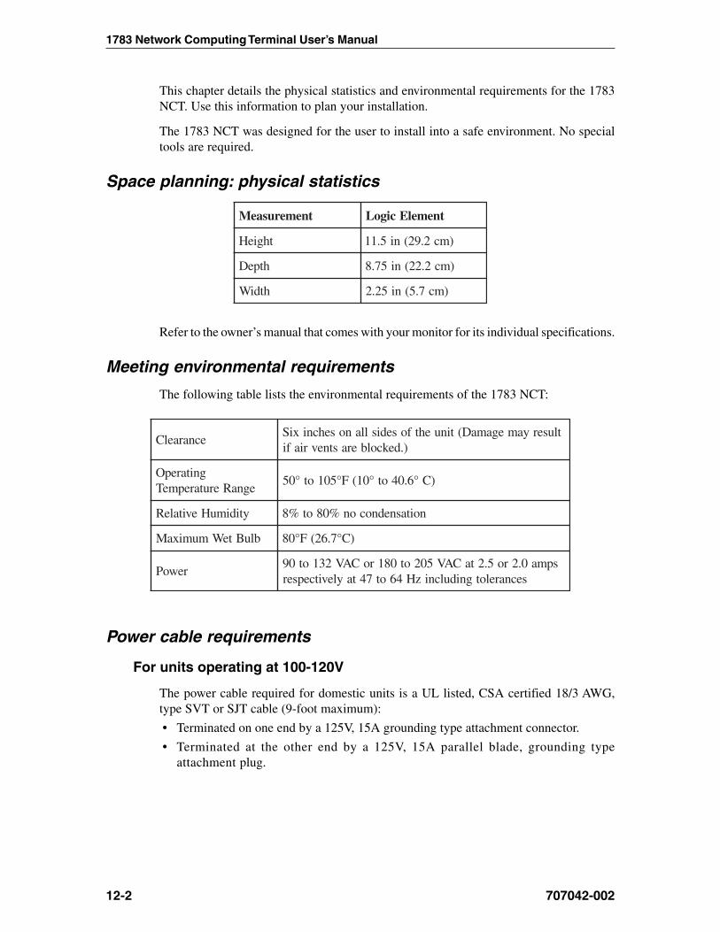
1783 Network Computing Terminal User’s Manual
707042-00212-2
This chapter details the physical statistics and environmental requirements for the 1783NCT. Use this information to plan your installation.
The 1783 NCT was designed for the user to install into a safe environment. No specialtools are required.
Space planning: physical statistics
tnemerusaeM tnemelEcigoL
thgieH )mc2.92(ni5.11
htpeD )mc2.22(ni57.8
htdiW )mc7.5(ni52.2
Refer to the owner’s manual that comes with your monitor for its individual specifications.
Meeting environmental requirements
The following table lists the environmental requirements of the 1783 NCT:
ecnaraelCtluseryamegamaD(tinuehtfosedisllanosehcnixiS
).dekcolberastnevriafi
gnitarepOegnaRerutarepmeT
)C°6.04ot°01(F°501ot°05
ytidimuHevitaleR noitasnednocon%08ot%8
bluBteWmumixaM )C°7.62(F°08
rewoPspma0.2ro5.2taCAV502ot081roCAV231ot09
secnarelotgnidulcnizH46ot74taylevitcepser
Power cable requirements
For units operating at 100-120V
The power cable required for domestic units is a UL listed, CSA certified 18/3 AWG,type SVT or SJT cable (9-foot maximum):
• Terminated on one end by a 125V, 15A grounding type attachment connector.
• Terminated at the other end by a 125V, 15A parallel blade, grounding typeattachment plug.

Chapter 12: Safety, Power, and Environmental Requirements
707042-002 12-3
For units operating at 200-240V
The power cable required for domestic units is a UL listed, CSA certified, 18/3 AWG,type SVT or SJT cable (9-foot maximum):
• Terminated on one end by a 250V, 15A grounding type attachment connector
• Terminated at the other end by a 250V, 15A tandem blade, grounding typeattachment plug.
For international units
The power cable required is an 18/3 AWG, type SJT cable (9-foot maximum):
• Terminated on one end by a 250V, 15A grounding type attachment plug body
• Terminated at the other end by a 250V, 15A grounding type cord connector.
The cord set is marked HAR to signify appropriate safety approvals. The socket outletmust be nearby and easily accessible, per IEC 950 Sec. 1.7.2.
Power outlet requirements
The installation site must provide a properly wired and grounded power outlet. Circuitsconnected to air conditioners and devices that generate significant transient electricalnoise should be avoided.
Electrical interference and atmospheric considerations
Electrostatic discharge in the vicinity of the unit should be minimized by avoiding highresistance floor material and carpeting that does not have anti-static properties, by avoidingthe use of plastic seats and covers, and by avoiding low humidity levels. The unit shouldbe located away from areas that generate electromagnetic interference (for example,transformers, power distribution panels, welding equipment, motors, and transmitters).Do not put the unit next to fluorescent lights. The 1783 NCT should not be installedwhere the atmosphere contains corrosive elements that can damage the unit.
Do not run the power cable or signal cables in areas that produce electromagneticinterference (for example, near transformers, switching equipment, welding equipment,power distribution panels, and under carpets where vacuum cleaning is done). Also, donot roll heavy equipment over the cable.

Chapter 13System Administrator’s Guide
In this Chapter...
Accessing the Configuration Screens
Administrator Functions
Configuring Options
Defining Administrator’s Password
Setting Date and Time
Configuring NCT Network
Configuring NCT Mail
Configuring NCT Applications
Configuring NCT Miscellaneous
ICA
NCT Update Configuration
Language Configuration
Ping

1783 Network Computing Terminal User’s Manual
707042-00213-2
This chapter explains how to configure features, local connections and remote connectionsin order to use the 1783 NCT successfully.
Most of the configuration screens are accessed by following the steps described below.One exception is the Voyager browser; for this information see Chapter 8, Accessing yourintranet and the Internet.
Accessing the configuration screens1. Click the button (located at the lower left-hand corner of the screen).
2. Select Config from the application menu.
If an Administrator Password has been set, the following screen will appear. If the passwordhas NOT been set, the Administrator Functions panel will appear and steps 3 and 4 shouldbe skipped.
3. Enter the Administrator Password.
4. Click Done when complete.
Note: The 1783 NCT is shipped from the manufacturer without a preset password. Todefine or change the password, refer to Defining Administrator’s Password in this chapter.

707042-002
Chapter 13: System Administrator’s Guide
13-3
Administrator Functions
Vital Product Data
The information provided in the 1783 NCT Administrator Functions panel will help withthe determination of hardware and software levels of your unit. Information that is providedin this panel is:
• Ethernet IP Address – Configured Ethernet IP Address
• Ethernet Mac Address – Media Access Control Address - a hardware address thatuniquely identifies each node of a network.
• Ethernet Subnet Mask – Configured Ethernet Subnet IP Address
• Default Gateway – Default Gateway IP Address
• Node Name – Configured Node Name
• Serial Number – Hardware serial number of the unit, provided during themanufacturing process.
• Integration Level – Software Integration level of the unit.
• COAX IP Address – Configured COAX IP Address
• COAX Mac Address – Media Access Control Address - a hardware address thatuniquely identifies each node of a network.
• Coax Subnet Mask – Configured Ethernet Subnet IP Address
• DNS Server – Domain Name Server primary IP Address
• Domain Name – Configured Domain Name
• Manufacture Date – Date and time the unit completed final testing.
• Manufacture Place – Location of the unit manufacturer.
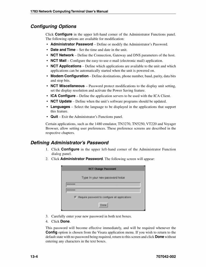
1783 Network Computing Terminal User’s Manual
707042-00213-4
Configuring Options
Click Configure in the upper left-hand corner of the Administrator Functions panel.The following options are available for modification:
• Administrator Password – Define or modify the Administrator’s Password.
• Date and Time – Set the time and date in the unit.
• NCT Network – Define the Connection, Gateway and DNS parameters of the host.
• NCT Mail – Configure the easy-to-use e-mail (electronic mail) application.
• NCT Applications – Define which applications are available to the unit and whichapplications can be automatically started when the unit is powered on.
• Modem Configuration – Define destinations, phone number, baud, parity, data bitsand stop bits.
• NCT Miscellaneous – Password protect modifications to the display unit setting,set the display resolution and activate the Power Saving feature.
• ICA Configure – Define the application servers to be used with the ICA Client.
• NCT Update – Define when the unit’s software programs should be updated.
• Languages – Select the language to be displayed in the applications that supportthis feature.
• Quit – Exit the Administrator’s Functions panel.
Certain applications, such as the 1480 emulator, TN3270, TN5250, VT220 and VoyagerBrowser, allow setting user preferences. These preference screens are described in therespective chapters.
Defining Administrator’s Password1. Click Configure in the upper left-hand corner of the Administrator Function
dialog panel.2. Click Administrator Password. The following screen will appear:
3. Carefully enter your new password in both text boxes.4. Click Done.
This password will become effective immediately, and will be required whenever theConfig option is chosen from the Visara application menu. If you wish to return to thedefault state with no password being required, return to this screen and click Done withoutentering any characters in the text boxes.

707042-002
Chapter 13: System Administrator’s Guide
13-5
Setting date and time1. Click Configure in the upper left-hand corner of the Administrator Functions panel.
2. Click Date and Time.
3. Use the arrow buttons to set the date and/or time.
4. Click Done when complete.
The unit must be restarted for date and time changes to become effective.
Configuring NCT Network1. Click Configure in the upper left-hand corner of the Administrator Function
dialog panel.
2. Click NCT Network. The following screen will appear, with tabbed sections forsetting the Connection, Gateway, and DNS parameters:
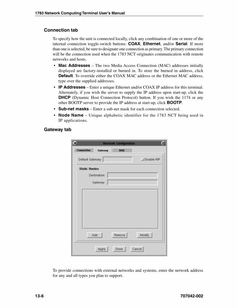
1783 Network Computing Terminal User’s Manual
707042-00213-6
Connection tab
To specify how the unit is connected locally, click any combination of one or more of theinternal connection toggle-switch buttons: COAX, Ethernet, and/or Serial. If morethan one is selected, be sure to designate one connection as primary. The primary connectionwill be the connection used when the 1783 NCT originates communication with remotenetworks and hosts.
• Mac Addresses – The two Media Access Connection (MAC) addresses initiallydisplayed are factory-installed or burned in. To store the burned in address, clickDefault. To override either the COAX MAC address or the Ethernet MAC address,type over the supplied addresses.
• IP Addresses – Enter a unique Ethernet and/or COAX IP address for this terminal.Alternately, if you wish the server to supply the IP address upon start-up, click theDHCP (Dynamic Host Connection Protocol) button. If you wish the 1174 or anyother BOOTP server to provide the IP address at start-up, click BOOTP.
• Sub-net masks – Enter a sub-net mask for each connection selected.
• Node Name – Unique alphabetic identifier for the 1783 NCT being used inIP applications.
Gateway tab
To provide connections with external networks and systems, enter the network addressfor any and all types you plan to support.

707042-002
Chapter 13: System Administrator’s Guide
13-7
Adding Gateway Connections• Default Gateway - Enter the Gateway address in the Default Gateway text block.
• Disable RIP - Selecting this button will disable the forwarding of Routing InformationProtocol packets received by the 1783.
• Static Routes- Enter Destination Static Route in the Destination Field.- Enter the Gateway in the Gateway field.
• Click Add to add the Static route
• Select the Static Route to be removed and click Remove to remove the static routefrom the table.
• Select the Static Route to be modified and click Modify to change the Static route.
• Click Apply to accept all the information that has been entered.
• Click Done to exit when complete.
• Click Cancel to discard changes and exit.
DNS tab
• Domain – Enter your organization’s domain name for the primary connection.
• Domain Name Servers – Enter the IP address of your organization’s domain nameserver. This is a mandatory field. Up to three server addresses may be entered; theaddress at the top of the list is always primary.

1783 Network Computing Terminal User’s Manual
707042-00213-8
Adding Domain Name Servers (DNS)
1. Enter the IP address of the DNS.
2. Click Add.
3. Click Apply.
Designating the Primary Domain Name Server
1. Select the address that should be primary.
2. Click Select Default. The address will be moved to the top of the list.
3. Click Apply.
Deleting Domain Name Servers
1. Click the DNS address to be deleted.
2. Click Remove to remove the highlighted DNS address.
3. Click Apply.
When all additions and/or changes are complete, click Done to close the screen.
Configuring NCT Mail1. Click Configure in the upper left-hand corner of the Administrator Functions
dialog panel.
2. Click NCT Mail. This configuration screen will appear:

707042-002
Chapter 13: System Administrator’s Guide
13-9
3. Enter your name.
4. Enter the following, which your Internet Service Provider will supply:UID (User ID), SMTP Server, POP Server, and POP Password. If Prompt forUser ID and POP Password on Mail Startup are selected, you will be asked toenter your User ID and POP Password each time NCT Mail is opened.
5. Enter an Operator Password. If Require Operator Password for Mail Entry isalso selected, you will be asked to enter this password each time NCT Mail is opened.
6. Click Done.
The unit must be restarted for changes to become effective.
Configuring NCT Applications1. Click Configure in the upper left-hand corner of the Administrator Function
dialog panel.
2. Click NCT Applications.
This screen specifies which applications are available to the terminal. Each applicationselected as loadable will be listed in the Start menu for the terminal.
• Loadable Applications – To specify that an application is to be available, selectthe application from the list of non-loadable applications and press Change. Theapplication will move to the loadable list.
• Non-Loadable Applications – To remove an application from the list of loadableapplications, select the application and press Change. The application will move tothe non-loadable list.
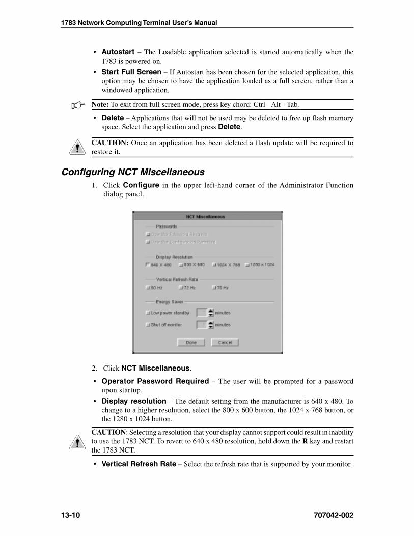
1783 Network Computing Terminal User’s Manual
707042-00213-10
• Autostart – The Loadable application selected is started automatically when the1783 is powered on.
• Start Full Screen – If Autostart has been chosen for the selected application, thisoption may be chosen to have the application loaded as a full screen, rather than awindowed application.
Note: To exit from full screen mode, press key chord: Ctrl - Alt - Tab.
• Delete – Applications that will not be used may be deleted to free up flash memoryspace. Select the application and press Delete.
CAUTION: Once an application has been deleted a flash update will be required torestore it.
Configuring NCT Miscellaneous1. Click Configure in the upper left-hand corner of the Administrator Function
dialog panel.
2. Click NCT Miscellaneous.
• Operator Password Required – The user will be prompted for a passwordupon startup.
• Display resolution – The default setting from the manufacturer is 640 x 480. Tochange to a higher resolution, select the 800 x 600 button, the 1024 x 768 button, orthe 1280 x 1024 button.
CAUTION: Selecting a resolution that your display cannot support could result in inabilityto use the 1783 NCT. To revert to 640 x 480 resolution, hold down the R key and restartthe 1783 NCT.
• Vertical Refresh Rate – Select the refresh rate that is supported by your monitor.

707042-002
Chapter 13: System Administrator’s Guide
13-11
• Energy Saver – If your display unit is Energy Star compliant, click the EnergyStar Display button, then select the Time Delay. When no keyboard or mouse activityis detected for the specified amount of time, the display unit will utilize its own powerdown circuitry and shut itself off.
If the display unit is not Energy Star compliant, click Display Power Off. After thespecified amount of time with no activity, the 1783 NCT logic unit will shut down thepower to the display unit. The display unit will not power off if plugged directly intoan electrical outlet instead of the logic unit.
Click Done when changes are complete. The unit must be restarted for changes to becomeeffective.
ICA
ICA (Independent Computing Architecture) is a presentation protocol used to establish aconnection to a Windows NT multi-user server. The ICA client enables users to run server-based windows applications from the 1783 desktop. Examples of multi-user NT serversinclude Citrix Winframe, NCD’s Wincenter PRO, and Microsoft’s Terminal Server Editionwith the Citrix Metaframe plug-in.
Configuring ICA1. Click Configure in the upper left-hand corner of the Administrator Functions dialog.
2. Click ICA Configure. The ICA client configuration panel (shown below) will appear:

1783 Network Computing Terminal User’s Manual
707042-00213-12
Application servers• Add – Add a new application server configuration.
• Remove – Remove an existing application server configuration. To remove anapplication server, highlight the server and click Remove.
• Default – Selects the default application server. To select a default server, highlightthe application server and click Default. If the 1783 is configured to auto-connect anICA session, the selected default application server will be used at POR.
• Description – User-defined application server name.
Note: The Description field may not contain the following characters: . (period), ?(question mark), = (equal sign), # (pound sign), [ (left bracket), or ] (right bracket).
Network tab• Domain – Server domain name
• Server – Application Server IP address
• User Name – Application Server Login ID
• Password – Application Server password.
Note: If the User Name and Password are omitted, the user will be prompted for thisinformation at login.
Connection Options tab• Cache Size – Bitmap caching to RAM stores commonly-used graphical objects
such as bitmaps in RAM on the local client. If your connection is bandwidth-limited,increasing the cache size will increase performance. If your client is on a high-speedLAN, you may not need to increase the cache size.

707042-002
Chapter 13: System Administrator’s Guide
13-13
• Window Resolution – Select the Window Resolution size. Available choices are:– Full Screen– 640x480– 800x600– 1024x768– Custom
• Color Resolution – Select either 16 or 256 color resolution
Application tab• Application - This field specifies the application to run once the logon to the server
is successful. It should be left blank to run a Windows desktop on the server. Enter thefully qualified drive and path of the program to run, followed by any necessarycommand line parameters and switches.
• Working Directory – This field specifies the working directory to use with theprogram specified in the Application field. Enter a working directory path in the field.
• Server Location – Enter the Master Browse IP Address in this field.

1783 Network Computing Terminal User’s Manual
707042-00213-14
Starting the ICA session
Select ICA from the Visara application menu. The Citrix ICA splash screen will appear.If an ICA connection has been configured, an ICA session will be established.
If an ICA connection was not configured or an attempt to establish a connection failed,the Application Server panel (shown below) will appear. The panel will also appear whenan ICA session is closed.
To reconnect or to connect to a different Application Server:
1. Highlight an Application Server from the Configured Applications list.
2. Click Connect.
To close the ICA program, click Done.

707042-002
Chapter 13: System Administrator’s Guide
13-15
NCT Update configuration
1783 NCT Update program allows programs and files to be updated from any FTP server onyour network. Updates can be done immediately or can be scheduled to take place at a timewhen network traffic is at a minimum. Updates can be programs that make up a newintegration level from Visara , Inc. or configuration files distributed by a system administrator.
The system administrator provides the address of the FTP server, the name and passwordrequired to access the server, and the path to the update list file on the server using theNCT Update panel (shown below), accessed from the Configuration drop down menu.
• Update Server Address – The IP address of the FTP server containing the updatelist and the new programs and files.
• Name – The user’s name expected by the file server (maximum 32 characters).
• Password – The user’s password on the file server (maximum 32 characters).
• Update List File – The file path of the file on the server that contains the list ofprograms and files to be updated.
• Do Update – The time when the update will automatically be started. The minutefield is changed in 5 minute increments using the arrows.
• Reboot 1783 upon completion – Select to reboot the 1783 after the update hascompleted.
Note: The program that starts NCT Update samples this time every 3 minutes, so theupdate process could begin 3 minutes after the selected update time.
• Automatic – The updates will be handled automatically at the time chosen bythe user.
• Immediate – Overrides the update time; the update process will begin immediately.
WARNING: All applications except the NCT Update program should be closed beforestarting an update. DO NOT shut off the machine or start any programs during the updateprocess. Notify the system administrator of any failures.

1783 Network Computing Terminal User’s Manual
707042-00213-16
NCT Update troubleshooting process
The NCT performs the software update in the following manner:
1. The NCT looks at the information provided in the configuration file for server addressand update list file. If one or more of these items are left blank or not in the correctformat, the NCT Update program will terminate. When the information is providedcorrectly, the next step is taken.
2. The NCT now attempts to establish communication with the designated server andretrieve the update list file (ULF) from the server. If the NCT is unable to locate orinitiate communication with the server, the NCT Update program will terminate.When the server is located and the ULF is obtained, the next step is taken.
3. The NCT will now verify that the Integration Level in the ULF is higher than theIntegration Level currently being used by the NCT. If it is not greater than the existingIntegration Level, the 1783 NCT Update program is terminated and the NCT will notbe updated. If the Integration Level is greater than the existing level being utilized bythe NCT, the program will be updated.
Note: An update can be left on the FTP server indefinitely, but a particular 1783 will onlyattempt the update once.
4. Once the NCT has established communication with the server, File Transfer Protocol(FTP) is opened with the user name and password. The files and programs that arecontained in the ULF are retrieved and written into the 1783 NCT’s flash memory.Each line in the ULF will execute as a complete transaction.
5. While the NCT is performing the file updates, a blue, green, and red full screen panelwill be displayed to warn the user to not start any programs or power-off the machine.
6. At the completion of each transaction attempt, the status of that transaction will bedisplayed in either the success or failed list on the panel.
7. When the update is completed, FTP is terminated and the OK button on the panel is“unblocked”. If all files were transferred successfully, the Integration Level shown inthe Administrator Functions panel will be updated to the new level.
Update list file format
The format of the update list is:
>noitanitseD<,>ecruoS<,>noitcA<
:noitcA
li|bc|pCnoitanitsedotelifecruosypoc>=pC
noitanitsedotelifecruosypocdnasserpmoc>=bC.lufsseccusetadpufi>ecruos<otlevelnoitargetniegnahc>=li
:ecruoS .)sretcarahc46(revresnoeliffohtapetelpmoC
:noitanitseD .)sretcarahc46(3861noeliffohtapetelpmoC
Note: The maximum number of transactions in the update list file is 128.
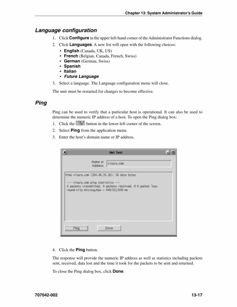
707042-002
Chapter 13: System Administrator’s Guide
13-17
Language configuration1. Click Configure in the upper left-hand corner of the Administrator Functions dialog.
2. Click Languages. A new list will open with the following choices:
• English (Canada, UK, US)• French (Belgian, Canada, French, Swiss)• German (German, Swiss)• Spanish• Italian• Future Language
3. Select a language. The Language configuration menu will close.
The unit must be restarted for changes to become effective.
Ping
Ping can be used to verify that a particular host is operational. It can also be used todetermine the numeric IP address of a host. To open the Ping dialog box:
1. Click the button in the lower-left corner of the screen.
2. Select Ping from the application menu.
3. Enter the host’s domain name or IP address.
4. Click the Ping button.
The response will provide the numeric IP address as well as statistics including packetssent, received, data lost and the time it took for the packets to be sent and returned.
To close the Ping dialog box, click Done.


707042-002 Index-1
Symbols
1480 CUT Emulatorabout, 6-2accessing applications, 6-3Base VPD, 6-10Coax indicator, 6-10Coax printer assignment, 6-15color setup, 6-13Configuring, 6-9Configuring Dual Screen mode, 6-19Controller Step Key = ChgSc, 6-10data entry features, 6-2Disable color override, 6-10DualScreen mode, 6-10, 6-19 - 6-24entering and editing data, 6-5Function (F or PF) keys, 6-6HAP menu, 6-16Increase session delay, 6-10key assignments, 6-21keyboard layout, 104-key, 6-7keyboard layout, 122-key, 6-8keyboard setup, 6-12local printing, 6-2LPR menu, 6-18Mark unprotected, 6-10miscellaneous setup, 6-11Monitoring response time, 6-9monitors for, 6-2moving the cursor, 6-4Printer setup, 6-14printing, 6-14Program Access (PA) function, 6-6remote printing, 6-2restarting, 6-11Row/Column indicator, 6-10Screen print mode, 6-24screen setup, 6-9selecting data fields, 6-5sending data, 6-6standard features, 6-2starting, 6-3starting Dual Screen mode, 6-20
1490 Twinax Emulatorcolor setup, 7-10communication setup, 7-3display address, 7-3keyboard setup, 7-4LPR menu, 7-13
miscellaneous, 7-13printer setup, 7-11restarting, 7-14screen setup, 7-8standard features, 7-2terminal mode, 7-3
1783 NCT3279 terminal, functioning as, 8-45250 terminal, functioning as, 8-16about, 2-2administrator functions, 13-2 - 13-17application window, 4-4as an LPR server, 5-8atmospheric considerations, 12-3back of logic unit, illustrated, 3-3configuration, 13-2electrical interference, 12-3environmental requirements, 12-2integration level, 13-3international units, power cable, 12-3manufacture date, 13-3monitor weight support, 3-2physical statistics, 12-2power cable requirements, 12-2power outlet requirements, 12-3safety requirements, 12-2 - 12-3serial number, 13-3setting up, 3-2standard features, 2-2starting, 4-2unpacking, 3-2updates, programs and files, 13-15using, 4-2VT220 display, functioning as, 8-23
A
Add printer, 5-3Administrator functions
accessing, 13-2date and time, setting, 13-5password, 13-2, 13-4vital product data, 13-3
Administrator passworddefining, 13-4entering, 13-2preset, 13-2
Answerback, VT220, 8-30Application server
ICA, 13-12
Index
1783 Network Computing Terminal User’s Manual
Index-2 707042-002
Audible alarm, 6-3Autostart, selecting application for, 13-10Available printers, 5-2
B
Base VPD, 1480 CUT Emulator, 6-10
C
Cachesize, ICA, 13-12Voyager Browser, 10-3
Calculator, 11-12Cautions, 1-3Citrix ICA Client, 2-2 See also ICAClose button, 4-4Coax indicator, 1480 CUT Emulator, 6-10Coax IP address, 13-3Coax Mac address, 13-3Coax printer assignment, 1480 CUT Emulator, 6-
15Coax printing
1480 CUT Emulator, 6-3Color setup
1480 CUT Emulator, 6-13TN3270, 8-11TN5250, 8-22VT220, 8-29
Colorsresolution, ICA, 13-13Voyager Browser, 10-4, 10-6
Communication setupTN5250, 8-17VT220, 8-24
Configuration, 1783 NCT, 13-2Configuration screens
accessing administrator functions, 13-2administrator password, 13-4color setup, TN3270, 8-11color setup, TN5250, 8-22color setup, VT220, 8-29communications setup, TN3270, 8-5communications setup, TN5250, 8-17communications setup, VT220, 8-24date and time, 13-5ISP setup, 11-14keyboard setup, TN3270, 8-10keyboard setup, TN5250, 8-21keyboard setup, VT220, 8-27miscellaneous setup, VT220, 8-30NCT applications, 13-9NCT mail, 13-8
NCT miscellaneous, 13-10NCT network, 13-5 - 13-8NCT update, 13-15print setup, TN3270, 8-12screen setup, TN3270, 8-9screen setup, TN5250, 8-20screen setup, VT220, 8-26WWW, 10-3 - 10-6
Configuringadministrator options, 13-4administrator password, 13-4connections, NCT network, 13-6Date and time, 13-5Dayminder preferences, 11-7Dial-up connection, 11-14Domain name servers, NCT network, 13-7energy saver, monitor, 13-11Gateway, NCT network, 13-6ICA client, 13-11language, 13-17NCT applications, 13-9NCT mail, 11-2, 13-8NCT miscellaneous, 13-10NCT network, 13-5NCT update, 13-15password, administrator, 13-4TN3270, applications for, 8-9TN5250, applications for, 8-20Voyager Browser, 10-2VT220, applications for, 8-26
Configuring remote printers, 5-7Controller Step Key = ChgSc, 1480 CUT
Emulator, 6-10CrSel key, 6-5
D
Date and time, setting, 13-5DayMinder
about, 11-6adding appointments, 11-8adding reminders, 11-9address book, 11-10appointment button bar, 11-7appointment panel, 11-7button bar, 11-6customizing, 11-7Menu bar, 11-6monthly calendar, 11-7preferences, 11-7reminders, 11-9reminders panel, 11-7
Index
707042-002 Index-3
starting, 11-6ToDo list, 11-8ToDo list, adding to, 11-9ToDo panel, 11-7weekly planner, 11-7window features, 11-6 - 11-7windows, resizing, 11-7
Default printer, changing, 5-3Dial-up connection
about, 11-13ISP setup, 11-14login script, 11-15modem setting, 11-15script editor, 11-16starting, 11-13
Disable color override, 1480 CUT Emulator, 6-10Domain name server, 13-7
adding, 13-8deleting, 13-8designating primary, 13-8
Doodle pad, 11-11Dual Screen mode
1480 CUT Emulator, 6-10, 6-21configuring, 6-19enhancements, 6-21starting, 6-20
E
E-mail See NCT MailEntering and editing data, 1480 CUT Emulator, 6-5Entry assist function, 6-3Environmental requirements, 12-2
F
Frame, 4-4Full screen mode, 4-5Function (F or PF) keys, 1480 CUT Emulator, 6-6
G
Graphics, printer, 5-5
H
HAP Menu, 1480 CUT Emulator, 6-16Hotlists, Voyager Browser
adding sites to, 10-8deleting sites from, 10-9viewing, 10-9
I
ICAapplication servers, 13-12configuring, 13-11starting session, 13-14
Increase session delay, 1480 CUT Emulator, 6-10Inspecting the package, 3-2Installed printers, 5-2Integration level, 13-3ISP
setup, 11-14TCP/IP settings, 11-15
K
Key assignments, 1480 CUT Emulator, 6-21Keyboard
chord instructions, 1-2input, 1-2shortcuts, 4-6
Keyboard layout1480 CUT Emulator, 104-key, 6-71480 CUT Emulator, 122-key, 6-81490 Twinax Emulator, 104-key, 7-51490 Twinax Emulator, 122-key - 3270, 7-71490 Twinax Emulator, 122-key - 5250, 7-6TN3270, 104-key, 8-7TN3270, 122-key, 8-8TN5250, 104-key, 8-18TN5250, 122-key, 8-19
Keyboard Setup1490 Twinax Emulator, 7-4
Keyboard setup1480 CUT Emulator, 6-12TN3270, 8-10TN5250, 8-21VT220, 8-27
L
Language configuration, 13-17Light-Pen, 1480 CUT Emulator, 6-3Loadable applications, 13-9Local printer, 5-2Local screen print
1480 CUT Emulator, 6-3printer connector, 3-2
LPR menu1480 CUT Emulator, 6-181490 Twinax Emulator, 7-13TN3270, 8-13

1783 Network Computing Terminal User’s Manual
Index-4 707042-002
LPR server, using the 1783 as, 5-8LPR/LPD print feature, 5-7
M
Margins, printer, 5-5Mark, 1480 CUT Emulator, 6-23Mark field, 1480 CUT Emulator, 6-23Mark Unprotected, 1480 CUT Emulator, 6-10Mark Unprotected field indicator, 6-2Mark/Paste, 1480 CUT Emulator, 6-23Maximize/Restore button, 4-4Message Pad, 2-3, 11-5Minimize button, 4-4Miscellaneous setup
1480 CUT Emulator, 6-11VT220, 8-30
Modemlogin script, 11-15script editor, 11-16settings, 11-15
Modifiable keyboard, 1480 CUT Emulator, 6-3Monitoring response time, 1480 CUT
Emulator, 6-9Mono/DualCase mode, 6-2, 8-4Mouse
click, 1-3, 4-3connecting, 3-2double-click, 1-3drag, 1-3, 4-3point, 1-3right button, 4-3using, 4-3
Mouse-Pen, 1480 CUT Emulator, 6-3Moving the cursor, 1480 CUT Emulator, 6-4
N
NCT applications, configuring, 13-9NCT Mail
checking for mail, 11-3configuring, 13-8forwarding mail, 11-3reading messages, 11-3replying to mail, 11-3sending new mail, 11-4starting, 11-2
NCT miscellaneous, configuring, 13-10NCT Network
configuring, 13-5connection, 13-6DNS, 13-7gateway, 13-6
NCT Updateconfiguration, 13-15troubleshooting, 13-16update list file format, 13-16
Non-loadable applications, 13-9Notes, 1-3Numeric lock, 1480 CUT Emulator, 6-2
O
Operator Password, 13-10
P
Paper selection, printer, 5-4Password, 4-2
administrator, 13-2Paste, 1480 CUT Emulator, 6-23Paste field, 1480 CUT Emulator, 6-23Photon micro-GUI, 2-2Physical statistics, 12-2Ping, 13-17Pointers
basic, 4-3busy, 4-3I-beam, 4-3move, 4-3no input, 4-3resize, 4-3
Power cableconnecting, 3-2
Power cable requirements, 12-2Power outlet requirements, 12-3Print preview, 5-6Print setup
1480 CUT Emulator, 6-14TN3270, 8-12VT220, 8-31
Print type, TN3270, 8-12Printer
adding, 5-3attached, 5-8available, 5-2color mode, 5-5default, 5-3graphics, 5-5install, 5-2installed, 5-2installing, 5-3local, 5-2margins, 5-5name, 5-8paper selection, 5-4
Index
707042-002 Index-5
properties, 5-2, 5-4remote, 5-2, 5-8set default, 5-2setup, 5-2uninstall, 5-2
Printing1480 CUT Emulator, 6-14screen Snapshot, 11-13Voyager Browser, 10-9
Printing features, 1480 CUT Emulator, 6-3
R
Remote hostconnecting to, TN3270, 8-6connecting to, TN5250, 8-17connecting to, VT220, 8-25logging in to, Telnet, 8-2logging out of, Telnet, 8-3logging out of, TN3270, 8-6logging out of, TN5250, 8-20logging out of, VT220, 8-25setting up, TN3270, 8-5setting up, TN5250, 8-16
Remote printersadding, 5-8configuring, 5-7support, 5-7
Resize corner, 4-4Resizing windows, DayMinder, 11-7Response time monitor
1480 CUT Emulator, 6-3Response time monitor, 1480 CUT Emulator, 6-3Right mouse button, 1-3, 4-3
S
Screen print mode, 1480 CUT Emulator, 6-24Screen setup
1480 CUT Emulator, 6-9TN3270, 8-9TN5250, 8-20VT220, 8-26
Select left, 1480 CUT Emulator, 6-21Select right, 1480 CUT Emulator, 6-21Selecting data fields, 1480 CUT Emulator, 6-5Sending data, 1480 CUT Emulator, 6-6Set default printer, 5-2, 5-3Setting up the 1783 NCT, 3-2Snapshot, 11-12
printing from, 11-13Standard features, 2-2Step Active session, 1480 CUT Emulator, 6-22
Swap session, 1480 CUT Emulator, 6-22Switchable Screen Formats, 1480 CUT
Emulator, 6-2
T
Taskbarfunctions, 4-2using, 4-5
Taskbar, accessing from full screen mode, 8-9,8-20, 8-26
Telnet sessionending, 8-3starting, 8-2
Telnet Terminal, 8-2logging in to a remote host, 8-2logging out of a remote host, 8-3
Title bar, 4-4TN3270
about, 8-4color setup, 8-11communications setup, 8-5configuring for an application, 8-9copy/paste between sessions, 8-14copy/paste from Calculator to, 8-15features, 8-4keyboard layout, 104-key, 8-7keyboard layout, 122-key, 8-8keyboard setup, 8-10LPR menu, 8-13print setup, 8-12print type, 8-12screen setup, 8-9session, connecting to, 8-6session, ending, 8-6setting up a remote host, 8-5
TN3270/TN5250 Keyboard Macros, 9-1delays, 9-4keystroke record/playback, 9-2pauses, 9-3playback speed, 9-4playing keystroke sequences, 9-3removing keystroke sequences, 9-3storing keystroke sequences, 9-2
TN5250about, 8-16color setup, 8-22communications setup, 8-17configuring for an application, 8-20keyboard layout, 104-key, 8-18keyboard layout, 122-key, 8-19keyboard setup, 8-21

1783 Network Computing Terminal User’s Manual
Index-6 707042-002
screen setup, 8-20session, connecting to, 8-20session, ending, 8-20setting up a remote host, 8-16
Toolbar icons, Voyager Browser, 10-7
U
User ID, 4-2
V
Vital Product Data, 13-3Voyager Browser
appearance, 10-6cache, 10-3configuring, 10-2connection, 10-5printing, 10-9toolbar icons, 10-7user info, 10-4
VT220about, 8-23color setup, 8-29configuring for an application, 8-26keyboard setup, 8-27miscellaneous setup, 8-30screen setup, 8-26session, connecting to, 8-25session, ending, 8-25setting up, 8-23
W
Warnings, 1-3Window menu
close, 4-5maximize, 4-5minimize, 4-5move, 4-5restore, 4-5size, 4-5to back, 4-5
Window menu button, 4-4Window operations, 4-6Workspace operations, 4-6
Z
Zoom key, 1480 CUT Emulator, 6-21