18000 pg 0510 - maxim crane works€¦ · 18,000 12,000 228 615 10,886 504,000 24,000 upperworks...
TRANSCRIPT

Manitowoc 18000 Product Guide
Features• 750 t (825 USt) capacity No. 55A boom with MAX-ER®
• 600 t (660 USt) capacity No. 55 boom
• 9 098 mton-m (65,505 ft-kips) maximum load moment with MAX-ER®
• 97,5 m (320 ft) No. 55 boom
• 149,3 m (490 ft) No. 79A luffing jib on No. 55 boom
• 447 kW (600 HP) engine

HydraulicsOur closed-loop system provides a separate hydraulic circuit to power each crane function. The result is truly independent, variable-speed operation of the swing, load hoist, boom hoist and travel functions.
EPIC®
Manitowoc’s field-proven Electronically Processed Independent Controls (EPIC) system delivers high productivity and precise load control by instantly matching a crane’s commands to the crane function. EPIC's microprocessor maximizes a Manitowoc crane's function capability and simplifies servicing by pinpointing any problem in the crane's engine, power transmission and other operating systems. In addition, EPIC increases versatility by easily tailoring a Manitowoc crane’s operation for specialized applications, with or without attachments. EPIC is a key reason no other crane can match the performance and reliability of Manitowoc.
Crawler Drive ShaftsThese eliminate the need to disconnect hydraulic systems for shipment— simplifying crawler removal and assembly.
FACT™ ConnectorsManitowoc’s patented Fast Aligning Connection Technology (FACT) automatically aligns crane components for fast, easy assembly.
Features

Specifications 4Outline dimensions 9Crane assembly 15Performance data 18Boom combinations 25Heavy-lift boom range / load charts 28Upper boom point range / load charts 32Fixed Jib range / load charts 34Luffing jib range / load charts 3 7MAX-ER® complete information 45Manitowoc Crane Care 60
Contents
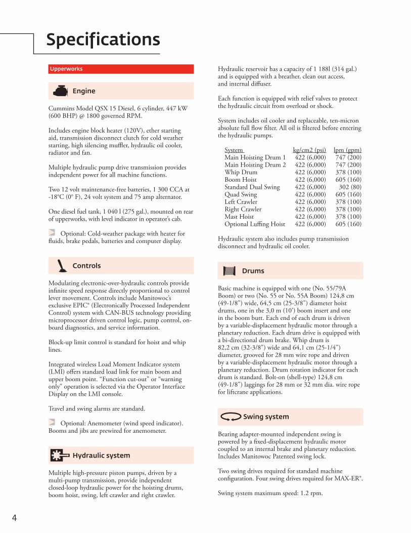
Upperworks
Engine
Cummins Model QSX 15 Diesel, 6 cylinder, 447 kW (600 BHP) @ 1800 governed RPM.
Includes engine block heater (120V), ether starting aid, transmission disconnect clutch for cold weather starting, high silencing muffler, hydraulic oil cooler, radiator and fan.
Multiple hydraulic pump drive transmission provides independent power for all machine functions.
Two 12 volt maintenance-free batteries, 1 300 CCA at -18°C (0° F), 24 volt system and 75 amp alternator.
One diesel fuel tank, 1 040 l (275 gal.), mounted on rear of upperworks, with level indicator in operator’s cab.
Optional: Cold-weather package with heater for fluids, brake pedals, batteries and computer display.
Controls
Modulating electronic-over-hydraulic controls provide infinite speed response directly proportional to control lever movement. Controls include Manitowoc’s exclusive EPIC® (Electronically Processed Independent Control) system with CAN-BUS technology providing microprocessor driven control logic, pump control, on-board diagnostics, and service information.
Block-up limit control is standard for hoist and whip lines.
Integrated wireless Load Moment Indicator system (LMI) offers standard load link for main boom and upper boom point. “Function cut-out” or “warning only” operation is selected via the Operator Interface Display on the LMI console.
Travel and swing alarms are standard.
Optional: Anemometer (wind speed indicator). Booms and jibs are prewired for anemometer.
Hydraulic system
Multiple high-pressure piston pumps, driven by a multi-pump transmission, provide independent closed-loop hydraulic power for the hoisting drums, boom hoist, swing, left crawler and right crawler.
Hydraulic reservoir has a capacity of 1 188l (314 gal.) and is equipped with a breather, clean out access, and internal diffuser.
Each function is equipped with relief valves to protect the hydraulic circuit from overload or shock.
System includes oil cooler and replaceable, ten-micron absolute full flow filter. All oil is filtered before entering the hydraulic pumps.
System kg/cm2 (psi) lpm (gpm)Main Hoisting Drum 1 422 (6,000) 747 (200) Main Hoisting Drum 2 422 (6,000) 747 (200) Whip Drum 422 (6,000) 378 (100) Boom Hoist 422 (6,000) 605 (160) Standard Dual Swing 422 (6,000) 302 (80) Quad Swing 422 (6,000) 605 (160) Left Crawler 422 (6,000) 378 (100) Right Crawler 422 (6,000) 378 (100) Mast Hoist 422 (6,000) 378 (100) Optional Luffing Hoist 422 (6,000) 605 (160)
Hydraulic system also includes pump transmission disconnect and hydraulic oil cooler.
Drums
Basic machine is equipped with one (No. 55/79A Boom) or two (No. 55 or No. 55A Boom) 124,8 cm (49-1/8") wide, 64,5 cm (25-3/8") diameter hoist drums, one in the 3,0 m (10') boom insert and one in the boom butt. Each end of each drum is driven by a variable-displacement hydraulic motor through a planetary reduction. Each drum drive is equipped with a bi-directional drum brake. Whip drum is 82,2 cm (32-3/8") wide and 64,1 cm (25-1/4") diameter, grooved for 28 mm wire rope and driven by a variable-displacement hydraulic motor through a planetary reduction. Drum rotation indicator for each drum is standard. Bolt-on (shell-type) 124,8 cm (49-1/8") laggings for 28 mm or 32 mm dia. wire rope for liftcrane applications.
Swing system
Bearing adapter-mounted independent swing is powered by a fixed-displacement hydraulic motor coupled to an internal brake and planetary reduction. Includes Manitowoc Patented swing lock.
Two swing drives required for standard machine configuration. Four swing drives required for MAX-ER®.
Swing system maximum speed: 1.2 rpm.
4
Specifications

Mast hoist system
Single drum mast hoist mounted in rotating bed is powered by a fixed displacement hydraulic motor and a planetary reduction gear box with internal brake. Ratcheting pawl is standard. Includes mast-hoist wire rope.
Boom hoist system
Independent boom hoist, mounted in the mast butt has grooved drum 1 168 mm (46") wide and 1 355 mm (53-3/8") diameter.
Each end of drum is powered by a variable- displacement hydraulic motor coupled to a planetary reduction gearbox with internal brake. Ratcheting pawl. rotation indicator, pressure roller and wire rope for 16-part boom hoist line are standard.
Boom hoist speed: raise 121,9 m (400') No. 55/79A main boom from 0°- 82° in 6 minutes, 6 seconds. Raise 97,5 m (320') No. 55 main boom from 0°- 82° in 6 minutes, 18 seconds.
Boom support system
Moving MastMoving mast is 9,1m (30') long and connects to the fixed mast suspension rigging. When used with the optional self-erect package, the mast is utilized for crane assembly and disassembly. It is capable of lifting and positioning the crawler assemblies.
Fixed MastStationary No. 56 lattice mast provides geometry to raise and support all boom lengths. 30,5 m (100') mast standard for basic crane; 42,7 m (140') mast required for MAX-ER® applications. Boom-hoist rope reeved from drum in mast butt through sheaves in mast top and boom-hoist equalizer forms 16-part boom-hoist rigging. High-strength steel straps connect equalizer to boom top.
Cushioned boom stop and automatic boom stop are standard.
Counterweight
Includes connecting pins, brackets, and stops.
Vision operator’s cab
The Vision Cab™ is a fully enclosed and insulated steel module mounted to the left front corner of rotating bed. Module is equipped with power tilt, sliding door, large safety glass windows on all sides and roof. Signal horn, power seat, all season climate control package, front and roof windshield wipers, dome light, sun visor and shade, fire extinguisher, swing and travel alarms, and radio/CD player are standard equipment. Operator’s station swings over front of rotating bed for transportation.
Lowerworks
Carbody
Connects rotating bed and crawler frames. Fabricated steel rotating bed lower module mounts to single- piece carbody by a 3 m (9' 10") diameter triple-row roller bearing turntable. Each crawler frame is mounted to the carbody with FACT™ connection system power-actuated pins. Crawler drive motors are mounted on carbody, permitting crawler removal without opening travel drive hydraulic circuit.
Crawlers
Crawler assemblies are 11,81 m (38' 9") long with 1,52 m (5') wide cast steel crawler pads and lubricated intermediate rollers. Each crawler is powered independently by two variable displacement hydraulic motors and includes two hydraulically powered pin actuators for fast installation and removal from carbody. Carbody mounted drive motors are connected to crawler final reduction via drive shafts. Crawlers provide ample tractive effort allowing counter-rotation with full rated load.
Maximum ground speed is 1,1 kph (0.7 mph).
Qty. Item Unit Weight Total Weight
kg lb kg lb
62
CarbodyLower BoxTray
19 95812 700
44,000 28,000
119 74825 400
264 00056,000
Carbody total 145 150 320,000
282
UpperworksUpper BoxTray
8 1654 443
18,00012,000
228 61510,886
504,00024,000
Upperworks total 239 497 528,000
Counterweight Total 384 647 848,000
Manitowoc 18000 5
Specifications

Attachments
No. 55-79A boom
The liftcrane is equipped with a 36,6 m (120') No. 55/79A tubular-chord boom consisting of a 6,1 m (20') No. 55 or No. 55A butt, 3,0 m (10') No. 55 or No. 55A insert, 6,1 m (20') No. 55 or No. 55A insert, 12,2 m (40') No. 55/79 transition insert with equalizer platform, and 9,1 m (30') No. 79A heavy-lift top with sixteen 762 mm (30") diameter roller bearing sheaves on one shaft. Includes rope guides, boom angle indicator, and a 27,2 t (30 USt) swivel hook and weight ball weighing 1270 kgs (2,800 lbs) for 28 mm or 32 mm wire rope. The No. 55/79A boom utilizes steel suspension straps and Manitowoc’s patented, exclusive FACT™ connection system.
Powered boom hinge system including cylinder, piping, operating controls, and locking device are standard.
Luffing jib preparation is standard.
Optional: 6,1 m (20'), and 12,2 m (40') No. 79 boom inserts with steel boom suspension straps, and FACT™ connection system.
Optional: 12,2 m (40') No. 55 or No. 55A boom insert with steel boom suspension straps, and FACT™ connection system.
Optional: 12,2 m (40') No. 55 or No. 55A boom insert with luffing drum sheaves, steel boom suspension straps, and FACT™ connection system.
Optional: Intermediate suspension, required for boom lengths of 109,7 m (360') or more.
Optional: Detachable upper boom point with one 762 mm (30") diameter tapered roller bearing steel sheave with rope guard, for liftcrane use on heavy-lift boom top. (Same upper point used on Models 555, 777, 777T, 888, M-250, and 2250.)
Optional: Extended upper boom point on boom 55/79A.
Utilize optional boom inserts in combination with the No. 55/79A basic boom for total lengths up to 121,9 m (400').
No. 55 or No. 55A boom
The liftcrane is equipped with a 36,6 m (120') No. 55 or No. 55A tubular-chord boom consisting of a 6,1 m (20') No. 55 or No. 55A butt, 3,0 m (10') No. 55 or No. 55A insert, 6,1 m (20') No. 55 or No. 55A insert, 12,2 m (40') No. 55 or No. 55A insert with equalizer platform, and 9,1 m (30') No. 55 or No. 55A heavy-lift top with sixteen 762 mm (30") diameter roller bearing sheaves on one shaft. Includes rope guides, boom angle indicator, and a 27,2 mT (30 ton) swivel hook and weight ball weighing 1 270 kgs (2,800 lbs.). The No. 55 or No. 55A boom utilizes steel suspension straps and Manitowoc's patented, exclusive FACT™ connection system.
Powered boom hinge system including cylinder, piping, operating controls, and locking device are standard.
Luffing jib preparation is standard.
Optional: 6,1 m (20'), 12,2 m (40') No. 55 or No. 55A boom inserts, and 12,2 m (40') No. 55 or No. 55A medium boom inserts with steel boom suspension straps, and FACT™ connection system.
Optional: 12,2 m (40') No. 55 or No. 55A boom insert with luffing drum sheaves, steel boom suspension straps, and FACT™ connection system.
Optional: Detachable upper boom point with one 762 mm (30") diameter tapered roller bearing steel sheave with rope guard, for liftcrane use on heavy-lift boom top. (Same upper point used on Models 555, 777, 777T, 888, M-250, and 2250.)
Optional: Detachable upper boom point with one 762 mm (30") diameter tapered roller bearing steel sheave with rope guard, for liftcrane use on No. 55 boom top or 79A luffing jib top.
Utilize optional boom inserts in combination with the No. 55 or No. 55A basic boom for total lengths up to 97,5 m (320').
6
Specifications

No. 79A fixed jib
Optional: Components to make up 15,2 m (50') basic fixed jib includes a 6,1 m (20') No. 79A butt, 9,1 m (30') No. 79A top, jib strut, backstay straps and jib support straps.
Optional: 6,1 m (20'), and 12,2 m (40') No. 79 inserts with steel boom suspension straps, and FACT™ connection system.
Utilize optional fixed jib inserts in combination with the No. 79A basic fixed jib for total lengths up to 33,5 m (110').
Note: Basic fixed jib 9,1 m (30') No. 79A boom top can be used from No. 55-79A boom. Fixed jib also uses No. 79 boom inserts and straps from MAX-ER® 2000 liftcrane.
The MAX-ER®
The MAX-ER® attachment components include:
One 12,2 m (40') No. 56 insert, added to increase the mast length to 42,7 m (140').
Two additional swing drives (for a total of four) mounted on the rotating module. Each swing drive is powered by a fixed-displacement hydraulic motor coupled to a planetary reduction gearbox and internal brake.
A wheeled or hanging MAX-ER® counterweight assembly attaches to the top of the mast by steel straps and to the rear of the upperworks by a shear- frame and to the top of the moving mast by steel straps for the 12,1 m (40') counterweight position.
The hanging MAX-ER® counterweight is 18 m (59') behind the crane's centerline of rotation, and the wheeled MAX-ER® counterweight is 12,1 m (40') or 18 m (59') behind the crane's centerline of rotation.
The wheeled counterweight uses large off-road tires, which can be positioned for traveling or swinging. It also includes hydraulic support jacks and pads.
No. 44 luffing jib
Optional: Components to make up 21,3 m (70') basic luffing jib include a 12,2 m (40') No. 44 butt, 9,1 m (30') No. 44 top, 15,2 m (50') jib strut with 7 sheaves, 14,3 m (47') main strut with 7 sheaves, jib strut stop, luffing jib stop, main luffing strut backstay straps, basic luffing jib steel rigging straps, combination upper point and luffing jib raising wheel, luffing drum assembly, 495 m (1625') luffing drum wire rope, and wire rope guide(s) as required.
Optional: 3,0 m (10'), 6,1 m (20'), and 12,2 m (40') No. 44 inserts with steel boom suspension straps.
Utilize optional luffing jib inserts in combination with the No. 44 basic luffing jib for total lengths up to 73,1 m (240').
Note: Basic luffing jib 12,2 m (40') No. 44 boom butt and 9,1 m (30') No. 44 boom top can be used from 2250 liftcrane. Luffing jib also uses No. 44 boom inserts and straps from 2250 liftcrane for luffing jib lengths greater than 21,3 m (70').
No. 79A luffing jib
Optional: Components to make up 21,3 m (90') basic luffing jib includes a 6,1 m (20') No. 79A butt, 12,2 m (40') No. 79 insert, 9,1 m (30') No. 79A top, jib strut, main strut, main jib strut stop, luffing jib stop, main luffing strut backstay straps, basic luffing jib steel rigging straps, upper point, luffing jib raising dolly, luffing drum assembly, luffing drum wire rope, and wire rope guide(s) as required.
Optional: 6,1 m (20'), and 12,2 m (40') No. 79 inserts with steel boom suspension straps, and FACT™ connection system.
Utilize optional luffing jib inserts in combination with the No. 79A basic luffing jib for total lengths up to 94,5 m (310').
Note: Basic luffing jib 9,1 m (30') No. 79A boom top can be used from No. 55-79A boom. Luffing jib also uses No. 79 boom inserts and straps from MAX-ER® 2000 liftcrane.
Manitowoc 18000 7
Specifications

Optional equipment
Optional: Self-erect system, includes: rotating bed jacking cylinders with pads, wireless controls, 91 t (100 ton) assembly block, crawler handling chains.
Optional: Blocks and Hooks
27,2 t (30 USt) swivel hook and weight ball 1 270 kgs (2,800 lb) for 28 mm or 32 mm wire rope.
250 t (275 UST) hook block 3 969 kgs (8,750 lbs) with nine 76,2 cm (30") dia. roller bearing sheaves and duplex roller bearing swivel hook with hook latch and swivel lock for 28 mm or 32 mm wire rope.
317 t (350 UST) hook block 7892 kgs (17,400 lbs) with nine 76,2 cm (30") dia. roller bearing sheaves and duplex roller bearing swivel hook with hook latch and swivel lock for 28 mm or 32 mm wire rope.
410 t (450USt) hook block 9 661 kgs (21,300 lbs) with thirteen 76,2 cm (30") dia. roller bearing sheaves and duplex roller bearing swivel hook, hook latch, and swivel lock. For 28 mm 32 mm wire rope.
450 t (500 USt) hook block 11 113 kgs (24,500 lbs) with fifteen 76,2 cm (30") dia. roller bearing sheaves and duplex roller bearing swivel hook, hook latch and swivel lock for 28 mm or 32 mm wire rope.
600 t (660 USt) hook block 11 385 kgs (25,100 lbs) with fifteen 76,2 cm (30") dia. roller bearing sheaves and duplex roller bearing swivel hook, hook latch and swivel lock for 28 mm or 32 mm wire rope.
700 t (770 USt) hook block 12 972 kgs (28,600 lbs) with seventeen 76,2 cm (30") dia. roller bearing sheaves and duplex roller bearing swivel hook, hook latch and swivel lock for 28 mm or 32 mm wire rope.
Optional: Preparation for MAX-ER®.
Optional: Hydraulic Test Kit: required to properlyanalyze the performance of the EPIC® control syste m.
Optional: Service Interval Kits: for the regularly scheduled maintenance of general crane operations.
Optional: Lighting Packages: consult Factory for available options.
Optional: Special Paint – color(s) other than Manitowoc standard red and black.
Optional: Custom vinyl decal(s) of customer name and/or logo from artwork supplied by customer.
Optional: Export Packaging: basic crane, boom and jib sections. MAX-ER® export packaging available.
8
Specifications

36,25 m (118' 11")
15,07 m (49' 5")
7,11 m (23' 4")
6,57 m (21' 7")
2,60 m (8' 6") 1,91 m
(6' 3")
1,78 m (5' 10")
1,52 m (5' 0")
3,46 m (11' 5")
5,44 m (17' 10")
5,00 m (16' 5")
2,07 m (6' 10")
37,51 m (123' 1")
10,16 m (33' 4")
9.01 m (29' 7")
5,88 m (19' 4")
11,81 m (38' 9")
16,05 m (52' 8")
15,62 m(51' 3")
1,52 m (5' 0")
3,46 m (11' 4")
3,00 m (9' 10")
R 10,18 m (33' 5")
TAILSWING
1,52 m (5' 0")
Manitowoc 18000 9
Outline dimensions

LiftcraneLength 13,59 m 44' 8"Width 3,00 m 9' 10"Height 2,69 m 8' 10"Weight 47 370 kg 104,434 lbWeight 40 068 kg 88,335 lbNote: Weight 1 includes rotating bed rear section with pin pullers, counterweight, live mast, mast-hoist with wire rope, maximum hoist and whip lines on drums, Cummins QSX15 powerplant upperworks jacking system, full hydraulic fluid reservoir, and half tank of fuel. Weight 2 is with upperworks jacking system removed.
Carbody and rotating bedLength 7,89 m 25' 11"Width 3,00 m 9'10"Height 3,33 m 11' 0"Weight 43 499 kg 95,900 lbNote: Weight includes rotating bed adapter frame with bearing turntable, four swing drives, and carbody.
Upperworks jacks x 4Length 3,29 m 10' 10"Width 1,14 m 3' 9"Height 0,31 m 1' 1"Weight 1 826 kg 4,025 lbNote: Shown in horizontal, retracted shipping position.
Crawlers x 2Length 11,81 m 38' 9"Width 2,20 m 7' 3"Height 2,07 m 6' 10"Weight 40 031 kg 88,225 lb
Carbody counterweight tray x 2Length 4,42 m 14' 6"Width 2,39 m 7' 10"Height 1,30 m 4' 4"Weight 12 700 kg 28,000 lb
Lower counterweight x 6Length 2,59 m 8' 6"Width 3,56 m 11' 8"Height 0,51 m 1' 8"Weight 19 958 kg 44,000 lb
L
H
L
H
L
H
L
H
W
H
W
H
Option
10
Outline dimensions

Upper counterweight tray x 2Length 2,84 m 9' 4"Width 3,24 m 10' 8"Height 2,38 m 7' 10"Weight 5 465 kg 12,050 lb
Upper counterweight x 28Length 2,54 m 8' 4"Width 2,61 m 8' 7"Height 0,41 m 1' 4"Weight 8 164 kg 18,000 lb
No. 56 mast butt and top package,drum, wire rope, equalizer x 1Length 15,11 m 49' 7"Width 3,00 m 9' 10"Height 2,79 m 9' 2"Weight 26 251 kg 57,875 lb
No. 56 mast insert 6,1 m (20') and straps x 1Length 6,30 m 20' 8"Width 3,00 m 8' 6"Height 2,49 m 9' 10"Weight 3 850 kg 8,490 lb
No. 56 mast insert 12,2 m (40') and straps x 1Length 12,45 m 40' 10"Width 3,00 m 8' 6"Height 2,49 m 9' 10"Weight 6 323 kg 13,940 lb
No. 55 or No. 55A boom butt6,1 m (20') with drum, rigging winch and wire rope x 1Length 6,62 m 21' 9"Width 3,00 m 9' 10"Height 3,10 m 10' 2"Weight 26 251 kg 57,875 lb
W
H
L
L
H
W
H
L
H
L
H
L
H
Option
Manitowoc 18000 11
Outline dimensions

No. 55 or No. 55A boom top 9,1 m (30') x 1Length 10,09 m 33' 2"Width 3,00 m 10' 6"Height 3,10 m 11' 4"Weight 17 137 kg 37,781 lb
No. 55 or No. 55A boom insert 3,0 m (10') with drum and wire rope x 1Length 6,35 m 20' 10"Width 3,00 m 9' 10"Height 3,10 m 10' 2"Weight 16,311 kg 35,960 lb
No. 55 or No. 55A boom insert6,1 m (20') x 1Length 6,35 m 20' 10"Width 3,00 m 9' 10"Height 3,10 m 10' 2"Weight 4 860 kg 10,715 lb
No. 55 or No. 55A boom insert 12,2 m (40') x 1Length 12,37 m 40' 7"Width 3,00 m 9' 10"Height 3,10 m 10' 2"Weight 8 384 kg 18,485 lb
No. 55/79A transition insertand straps 12,2 m (40') x 1Length 12,37 m 40' 7"Width 3,00 m 9' 10"Height 3,10 m 10' 2"Weight 8 908 kg 19,640 lb
No. 79A boom top 9,1 m (30') x 1Length 10,05 m 33' 0"Width 3,00 m 9' 10"Height 3,10 m 11' 3"Weight 12 625 kg 27,835 lb
L
H
L
H
L
H
L
H
H
L
L
H
Option
12
Outline dimensions

No. 79 boom insert 6,1 m (20') x 1Length 6,27 m 20' 7"Width 3,00 m 9' 10"Height 3,09 m 10' 2"Weight 3 553 kg 7,835 lb
No. 79 boom insert 12,2 m (40') x 1Length 12,37 m 40' 7"Width 3,00 m 9' 10"Height 3,09 m 10' 2"Weight 5 978 kg 13,180 lb
Extended upper boom point 7,6 m (25') x 1Length 10,49 m 34' 5"Width 2,70 m 8' 10"Height 2,34 m 7' 8"Weight 5 198 kg 11,460 lb
No. 79 luffing jib butt 6,1 m (20') x 1Length 6,63 m 21' 9"Width 3,00 m 9' 10"Height 3,09 m 10' 2"Weight 13 527 kg 29,822 lb
No. 79 luffing jib main masts 12,2 m (40') x 1Length 16,15 m 53' 0"Width 2,51 m 8' 3"Height 2,36 m 7' 9"Weight 10 544 kg 23,245 lb
No. 44 luffing jib butt12,2 m (40') x 1Length 12,78 m 41' 11"Width 3,00 m 9' 10"Height 3,00 m 9' 10"Weight 5 194 kg 11,450 lb
No. 44 luffing jib masts12,2 m (40') x 1Length 16,15 m 53' 0"Width 2,51 m 8' 3"Height 2,36 m 7' 9"Weight 10 544 kg 23,245 lb
L
H
L
H
L
H
H
L
L
H
L
H
Option
H
L
Manitowoc 18000 13
Outline dimensions

No. 44 boom top 9,1 m (30') and wire rope guide, straps, lower point x 1Length 10,06 m 33' 0"Width 2,59 m 8' 6"Height 2,90 m 9' 6"Weight 5 657 kg 12,475 lb
No. 44 luffing jib insert 3,0 m (10') x 1Length 3.23 m 10' 7"Width 2,59 m 8' 6"Height 2,59 m 8' 6"Weight 857 kg 1,890 lb
No. 44 luffing jib insert 6,1 m (20') x 1Length 6,28 m 20' 7"Width 2,59 m 8' 6"Height 2,59 m 8' 6"Weight 1 458 kg 3,215 lb
No. 44 luffing jib insert 12,2 m (40') x 1Length 12,38 m 40' 7"Width 2,59 m 8' 6"Height 2,59 m 8' 6" Weight 2 458 kg 5,420lb
No. 79A fixed jib butt 6,1 m (20') x 1Length 6,52 m 21' 5" Width 3,00 m 9' 10" Height 3,02 m 9' 11" Weight 4 482 kg 9,880 lb
No. 79A fixed jib strut12,2 m (40') x 1Length 9,61 m 31' 6"Width 2,97 m 9' 9"Height 2.92 m 9' 7" Weight 622 kg 16,802 lb
L
H
L
H
L
H
L
H
L
H
L
H
Option
14
Outline dimensions
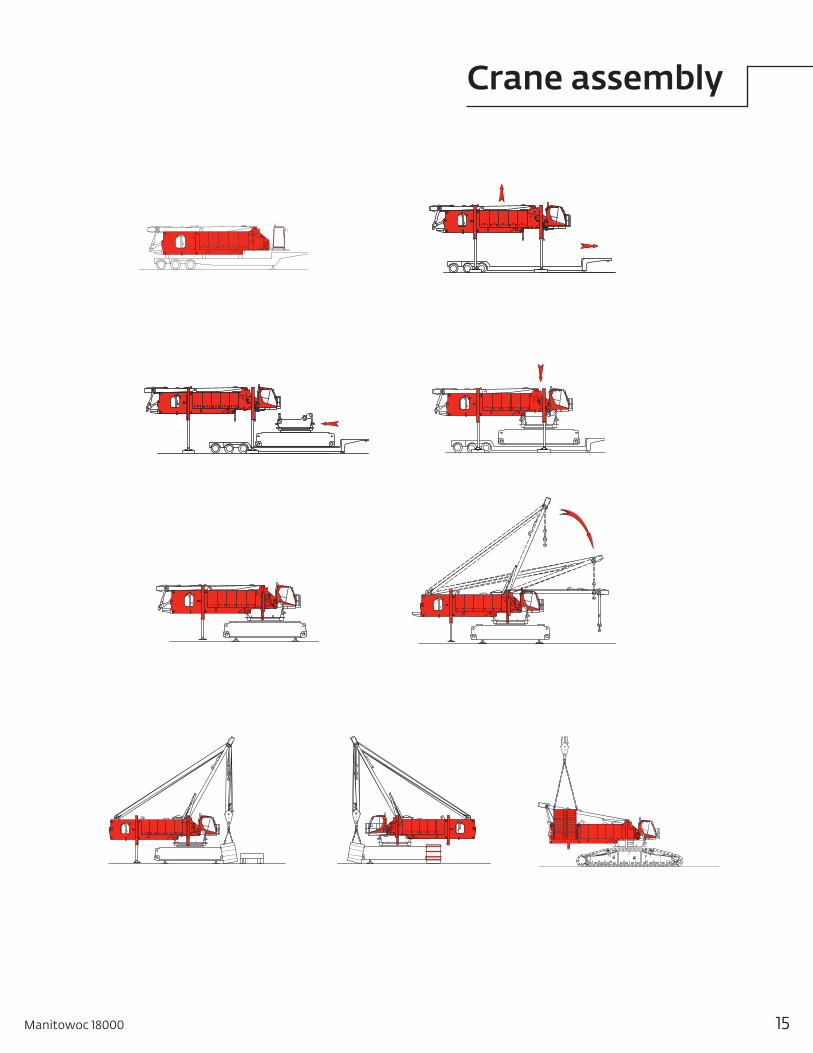
1
2
3
6 7
9 1011
4
Manitowoc 18000 15
Crane assembly

1M
3M
2M
6M
16
Crane assembly

1
9
2
Manitowoc 18000 17
Crane assembly

NOTE: Above hoist line lengths are based on tandem drums both reeved to the main load block. Each drum is dead-ended in main load block reeving. Total parts of line requires using both drums 1 and 2. Hoist and whip line lengths will allow hook to touch ground. When block travel below ground is required, add additional rope equal to parts of the line times the added travel distance. Hoisting distance or line pull may be limited when block travel below ground is required.
m
579
671
762
853
853
914
975
975
975
975
975
(ft)
(1900)
(2200)
(2500)
(2800)
(2800)
(3000)
(3200)
(3200)
(3200)
(3200)
(3200)
Boom orboom and
fixed jib length
m (ft)
36,6 (120)
42,7 (140)
48,8 (160)
54,9 (180)
61,0 (200)
67,1 (220)
73,2 (240)
79,2 (260)
85,3 (280)
91,4 (300)
97,5 (320)
Wire rope lengths - tandem drums - 28 mm hoist lineboom No. 55 or No. 55A
Whip line Hoist line
m
91
99
114
122
137
152
160
175
183
198
213
(ft)
(300)
(325)
(375)
(400)
(450)
(500)
(525)
(575)
(600)
(650)
(700)
m
579
671
762
853
853
914
975
975
975
975
975
(ft)
(1900)
(2200)
(2500)
(2800)
(2800)
(3000)
(3200)
(3200)
(3200)
(3200)
(3200)
Drum 3(1 part of line)
m
130
145
168
183
206
221
236
259
274
297
312
(ft)
(425)
(475)
(550)
(600)
(675)
(725)
(775)
(850)
(900)
(975)
(1025)
Drum 3(2 parts of line)
Drum 1 Total parts of
line
28
28
28
28
24
24
24
20
20
16
16
Drum 2
No. parts of line
2
4
6
8
10
12
14
16
18
20
22
24
26
28
30
Maximum loadkg (lb)
32 520 71,700
65 090 143,500
97 610 215,200
130 180 287,000
162 750 358,800
195 270 430,500
227 840 502,300
258 000 568,800
287 440 633,700
316 290 697,300
344 550 759,600
372 260 820,700
399 430 880,600
426 060 939,300
452,600 996,800
Hoist reeving for main load block single lead line - 28 mm boom No. 55 or No. 55A
No. parts of line
8
12
16
20
24
28
Maximum loadkg (lb)
130 180 287,000
195 270 430,500
260 360 574,000
325 500 717,600
390 540 861,000
455 600 1,004,600
Hoist reeving for main load block two lead lines - 28 mm boom No. 55 or No. 55A
NOTE: Above hoist line lengths are based on single part lead line. Hoist and whip line lengths will allow hook to touch ground. When block travel below ground is required, add additional rope equal to parts of the line times the added travel distance. Hoisting distance or line pull may be limited when block travel below ground is required.
Boom length m (ft)
36,6 (120)
42,7 (140)
48,8 (160)
54,9 (180)
61,0 (200)
67,1 (220)
73,2 (240)
79,2 (260)
85,3 (280)
91,4 (300)
97,5 (320)
Wire rope lengths - single hoist drum - 28 mm hoist line boom No. 55 or No. 55A
Whip line - drum 2 or 3 Hoist line - drum 1
m
91
99
114
122
137
152
160
175
183
198
213
(ft)
(300)
(325)
(375)
(400)
(450)
(500)
(525)
(575)
(600)
(650)
(700)
m
1189
1372
1463
1463
1463
1463
1463
1463
1463
1463
1463
(ft)
(3900)
(4500)
(4800)
(4800)
(4800)
(4800)
(4800)
(4800)
(4800)
(4800)
(4800)
1 part
m
130
145
168
183
206
221
236
259
274
297
312
(ft)
(425)
(475)
(550)
(600)
(675)
(725)
(775)
(850)
(900)
(975)
(1025)
2 partMaximum
parts of line for full
hoisting range
30
30
28
24
22
20
18
16
14
14
12
18
Performance data

NOTE: Above hoist line lengths are based on tandem drums both reeved to the main load block. Each drum is dead-ended in main load block reeving. Total parts of line requires using both drums 1 and 2. Hoist and whip line lengths will allow hook to touch ground. When block travel below ground is required, add additional rope equal to parts of the line times the added travel distance. Hoisting distance or line pull may be limited when block travel below ground is required.
m
579
579
671
671
701
701
701
732
792
792
792
(ft)
(1900)
(1900)
(2200)
(2200)
(2300)
(2300)
(2300)
(2400)
(2600)
(2600)
(2600)
Boom length
m (ft)
36,6 (120)
42,7 (140)
48,8 (160)
54,9 (180)
61,0 (200)
67,1 (220)
73,2 (240)
79,2 (260)
85,3 (280)
91,4 (300)
97,5 (320)
Wire rope lengths - tandem drums - 32 mm hoist line boom No. 55 or No. 55A
Whip line Hoist line
m
91
99
114
122
137
152
160
175
183
198
213
(ft)
(300)
(325)
(375)
(400)
(450)
(500)
(525)
(575)
(600)
(650)
(700)
m
579
579
671
671
701
701
701
732
792
792
792
(ft)
(1900)
(1900)
(2200)
(2200)
(2300)
(2300)
(2300)
(2400)
(2600)
(2600)
(2600)
Drum 3(1 part of line)
m
130
145
168
183
206
221
236
259
274
297
312
(ft)
(425)
(475)
(550)
(600)
(675)
(725)
(775)
(850)
(900)
(975)
(1025)
Drum 3(2 parts of line)
Drum 1 Total parts of
line
28
24
24
20
20
16
16
16
16
12
12
Drum 2
Maximum load kg (lb)
44 270 97,600
88 540 195,200
132 810 292,800
177 080 390,400
221 350 488,000
265 620 585,600
309 890 683,200
350 900 773,600
390 950 861,900
430 190 948,400
468 650 1,033,200
506 350 1,116,300
543 270 1,197,700
579 400 1,277,500
No. parts of line
2
4
6
8
10
12
14
16
18
20
22
24
26
28
Hoist reeving for main load block single lead line - 32 mm boom No. 55 or No. 55A
NOTE: Above hoist line lengths are based on single part lead line. Hoist and whip line lengths will allow hook to touch ground. When block travel below ground is required, add additional rope equal to parts of the line times the added travel distance. Hoisting distance or line pull may be limited when block travel below ground is required.
Boom length
m (ft)
36,6 (120)
42,7 (140)
48,8 (160)
54,9 (180)
61,0 (200)
67,1 (220)
73,2 (240)
79,2 (260)
85,3 (280)
91,4 (300)
97,5 (320)
Wire rope lengths - single hoist drum - 32 mm hoist line boom No. 55 or No. 55A
Whip line - drum 2 or 3 Hoist line - drum 1
m
91
99
114
122
137
152
160
175
183
198
213
(ft)
(300)
(325)
(375)
(400)
(450)
(500)
(525)
(575)
(600)
(650)
(700)
m
1128
1128
1128
1128
1128
1128
1128
1128
1128
1128
1128
(ft)
(3700)
(3700)
(3700)
(3700)
(3700)
(3700)
(3700)
(3700)
(3700)
(3700)
(3700)
1 Part
m
130
145
168
183
206
221
236
259
274
297
312
(ft)
(425)
(475)
(550)
(600)
(675)
(725)
(775)
(850)
(900)
(975)
(1025)
2 PartMaximum
parts of line for full
hoisting range
28
24
20
18
16
14
14
12
12
10
10
Maximum loadkg (lb)
177 080 390,400
265 620 585,600
354 160 780,800
442 710 976,000
531 250 1,171,200
600 000 1,322,800
No. parts of line
8
12
16
20
24
28
Hoist reeving for main load block two lead lines - 32 mm boom No. 55 or No. 55A
Manitowoc 18000 19
Performance data

Drum 1 (hoist line) 32 mm wire rope*
Drum 2 (Hoist or Whip Line) (32 mm) Wire Rope*
Drum 3 (Whip Line) 28 mm wire rope
1 015 m (3,330 ft)9 layers
1 015 m (3,330 ft)9 layers
579 m (1,900 ft)8 layers
Maximum spooling capacities
*7 m (23 ft) is deducted from maximum spooling capacities for 3 dead wraps per drum.
Refer to Drum and Lagging Chart No. 8512-A and Load Block Reeving Folio No. 2032
No. parts of line
2
4
6
8
10
12
14
16
18
20
22
24
26
28
30
Maximum loadkg (lb)
32 520 71,700
65 090 143,500
97 610 215,200
130 180 287,000
162 750 358,800
195 270 430,500
227 840 502,300
258 000 568,800
287 440 633,700
316 290 697,300
344 550 759,600
372 260 820,700
399 430 880,600
426 060 939,300
453 500 1,000,000
Hoist reeving for main load block single lead line - 28 mm boom No. 55-79A
Wire rope lengths - single hoist drum - 28 mm hoist line boom No. 55-79A
Whip line - drum 2 or 3 Hoist line - drum 1
1 part 2 part
NOTE: Hoist and whip line lengths will allow hook to touch ground. When block travel below ground is required, add additional rope equal to parts of the line times the added travel distance. Hoisting distance or line pull may be limited when block travel below ground is required.
Boom length
m (ft)
36,6 (120)
42,7 (140)
48,8 (160)
54,9 (180)
61,0 (200)
67,1 (220)
73,2 (240)
79,2 (260)
85,3 (280)
91,4 (300)
97,5 (320)
103,6 (340)
109,7 (360)
115,8 (380)
121,9 (400)
m
91
99
114
122
137
152
160
175
183
198
213
221
236
244
259
(ft)
(300)
(325)
(375)
(400)
(450)
(500)
(525)
(575)
(600)
(650)
(700)
(725)
(775)
(800)
(850)
m
1189
1372
1463
1463
1463
1463
1463
1463
1463
1463
1463
1463
1463
1463
1463
(ft)
(3900)
(4500)
(4800)
(4800)
(4800)
(4800)
(4800)
(4800)
(4800)
(4800)
(4800)
(4800)
(4800)
(4800)
(4800)
m
130
145
168
183
206
221
236
259
274
297
312
328
351
366
389
(ft)
(425)
(475)
(550)
(600)
(675)
(725)
(775)
(850)
(900)
(975)
(1025)
(1075)
(1150)
(1200)
(1275)
Maximum parts of
line for full hoisting
range
30
30
28
24
22
20
18
16
14
12
12
10
10
8
8
Wire rope specifications 5:1 safety factor - 32 mm hoist line - boom No. 55 or No. 55A
FunctionMCC part number
Size wire rope
Minimum breakingstrength
Maximum loadper line
Approximate weight
Hoist line
(Drum 1)
A06005
32 mm
110 680 kg(244,000 lb)
5.57 kg/m (3.74 lb/ft)
Hoist or whip line
(Drum 2)
A06005
32 mm
110 680 kg(244,000 lb)
22 140 kg(48,800 lb)
5.57 kg/m(3.74 lb/ft)
Whip line
(Drum 3)
719425
28 mm
81 370 kg(179,400 lb)
13 610 kg(30,000 lb)
4.11 kg/m(2.76 lb/ft)
Rotation resistant, right hand lang lay wire rope with spelter button (except 719425) and pad eye
20
Performance data

Application
Hoist
Hoist or whip
Whip
Drum and lagging chart - liftcrane
Drum number and
location
Drum 1 (boom insert)
Drum 2 (boom butt)
Drum 3 (rotating
bed)
Drum part number
A05163
A05163
A05302
Drumtype
Bare
Bare
Grooved
Drumdiameter
645 mm(25-3/8")
645 mm(25-3/8")
641 mm(25-1/4")
Drumwidth
1248 mm(49-1/8")
1248 mm(49-1/8")
822 mm(32-3/8")
Lagging diameter
714 mm (28-1/8")
714 mm (28-1/8")
714 mm (28-1/8")
714 mm (28-1/8")
Minimumwire rope
size
28 mm
32 mm
28 mm
32 mm
28 mm
Grooved lagging
part number
A05084
A05085
A05084
A05085
Drum 1 (hoist line) 28 mm wire rope*
Drum 2 (hoist or whip line) (28 mm) wire rope*
Drum 3 (whip line) 28 mm wire rope
1 440 m (4,723 ft)11 layers
1 440 m (4,723 ft)11 layers
579 m (1,900 ft)8 layers
Maximum spooling capacities
*7 m (23 ft) is deducted from maximum spooling capacities for 3 dead wraps per drum.
Refer to Drum and Lagging Chart No. 8512-A and Load Block Reeving Folio No. 2003 for Boom No. 55 or 55A.
Refer to Drum and Lagging Chart No. 8512-A and Load Block Reeving Folio No. 2032 for Boom No. 55-79A.
FunctionMCC part number
Size wire rope
Minimum breakingstrength
Maximum loadper line
Approximate weight
Hoist line
(Drum 1)
719425
28 mm
81 370 kg(179,400 lb)
4.11 kg/m (2.76 lb/ft)
Hoist or whip line
(Drum 2)
719425
28 mm
81 370 kg(179,400 lb)
16 240 kg (35,800 lb)
4.11 kg/m (2.76 lb/ft)
Whip line
(Drum 3)
719425
28 mm
81 370 kg(179,400 lb)
13 610 kg (30,000 lb)
4.11 kg/m (2.76 lb/ft)
Rotation resistant, right hand lang lay wire rope with pad eye
Wire rope specifications 5:1 safety factor - 28 mm boom No. 55 or No. 55A and boom No. 55-79A
Drum number
1
2
3
4
5
6
7
Function
Main load drum – standard
Main/auxiliary load drum – standard
Whip hoist – standard
Boom hoist – standard
Mast hoist – standard
Luffing jib drum – optional
Rigging winch – optional (not shown, located in butt)
Drum identification 4
1
6
2
3
5
Manitowoc 18000 21
Performance data

No. parts of line
2
4
6
8
10
12
14
16
18
20
22
Maximum load kg (lb)
44 270 97,600
88 540 195,200
132 810 292,800
177 080 390,400
221 350 488,000
265 620 585,600
309 890 683,200
350 900 773,600
390 950 861,900
430 190 948,400
453 500 1,000,000
Hoist reeving for main load block single lead line - 32 mm boom No. 55-79A
NOTE: Hoist and whip line lengths will allow hook to touch ground. When block travel below ground is required, add additional rope equal to parts of the line times the added travel distance. Hoisting distance or line pull may be limited when block travel below ground is required.
Boom length
m (ft)
36,6 (120)
42,7 (140)
48,8 (160)
54,9 (180)
61,0 (200)
67,1 (220)
73,2 (240)
79,2 (260)
85,3 (280)
91,4 (300)
97,5 (320)
103,6 (340)
109,7 (360)
115,8 (380)
121,9 (400)
Wire rope lengths - single hoist drum - 32 mm hoist lineboom No. 55-79A
Whip line - drum 2 or 3 Hoist line - drum 1
m
91
99
114
122
137
152
160
175
183
198
213
221
236
244
259
(ft)
(300)
(325)
(375)
(400)
(450)
(500)
(525)
(575)
(600)
(650)
(700)
(725)
(775)
(800)
(850)
m
884
1036
1067
1097
1097
1097
1128
1128
1128
1128
1128
1128
1128
1128
1128
(ft)
(2900)
(3400)
(3500)
(3600)
(3600)
(3600)
(3700)
(3700)
(3700)
(3700)
(3700)
(3700)
(3700)
(3700)
(3700)
1 part
m
130
145
168
183
206
221
236
259
274
297
312
328
351
366
389
(ft)
(425)
(475)
(550)
(600)
(675)
(725)
(775)
(850)
(900)
(975)
(1025)
(1075)
(1150)
(1200)
(1275)
2 partMaximum
parts of line for full
hoisting range
22
22
20
18
16
14
14
12
10
10
10
8
6
6
6
Wire rope lengths - single hoist drum - 28 mm hoist line boom No. 55-79A with 7.6 m (25 ft) extended upper boom point
Whip line - drum 2 or 3 Hoist line - drum 1
1 part 2 partBoom length
m (ft)
61,0 (200)
67,1 (220)
73,2 (240)
79,2 (260)
85,3 (280)
91,4 (300)
97,5 (320)
103,6 (340)
109,7 (360)
115,8 (380)
121,9 (400)
m
152
168
175
191
206
213
229
236
251
267
274
(ft)
(500)
(550)
(575)
(625)
(675)
(700)
(750)
(775)
(825)
(875)
(900)
m
640
701
762
823
884
914
975
1036
1097
1097
1097
(ft)
(2100)
(2300)
(2500)
(2700)
(2900)
(3000)
(3200)
(3400)
(3600)
(3600)
(3600)
m
229
244
259
282
297
312
335
351
373
389
404
(ft)
(750)
(800)
(850)
(925)
(975)
(1025)
(1100)
(1150)
(1225)
(1275)
(1325)
Total parts of line
8
8
8
8
8
8
8
8
8
6
6
NOTE: Hoist and whip line lengths will allow hook to touch ground. When block travel below ground is required, add additional rope equal to parts of the line times the added travel distance. Hoisting distance or line pull may be limited when block travel below ground is required.
No. parts of line
2
4
6
8
Maximum load kg (lb)
32 520 71,700
65 090 143,500
97 610 215,200
130 180 287,000
Hoist reeving for main load block single lead line - 28 mm boom No. 55-79A with 7.6 m (25 ft) extended upper boom point
22
Performance data

Wire rope lengths - single hoist drum - 32 mm hoist line boom No. 55-79A with 7.6 m (25 ft) extended upper boom point
Whip line - drum 2 or 3 Hoist line
1 part 2 partBoom length
m (ft)
61,0 (200)
67,1 (220)
73,2 (240)
79,2 (260)
85,3 (280)
91,4 (300)
97,5 (320)
103,6 (340)
109,7 (360)
115,8 (380)
121,9 (400)
m
152
168
175
191
206
213
229
236
251
267
274
(ft)
(500)
(550)
(575)
(625)
(675)
(700)
(750)
(775)
(825)
(875)
(900)
m
518
549
610
640
671
732
762
823
853
853
853
(ft)
(1700)
(1800)
(2000)
(2100)
(2200)
(2400)
(2500)
(2700)
(2800)
(2800)
(2800)
m
229
244
259
282
297
312
335
351
373
389
404
(ft)
(750)
(800)
(850)
(925)
(975)
(1025)
(1100)
(1150)
(1225)
(1275)
(1325)
Total parts of line
6
6
6
6
6
6
6
6
6
4
4
NOTE: Hoist and whip line lengths will allow hook to touch ground. When block travel below ground is required, add additional rope equal to parts of the line times the added travel distance. Hoisting distance or line pull may be limited when block travel below ground is required.
No. parts of line
2
4
6
Maximum load kg (lb)
44 270 97,600
88 540 195,200
132 810 292,800
Hoist reeving for main load block single lead line - 32 mm boom No. 55-79A with 7.6 m (25 ft) extended upper boom point
30,5 m (100') No. 56 mastwith36,6 m (120')No. 55 or No. 55A main boom,upper boom point, 661 t (600 USt) hook block.
30,5 m (100') No. 56 mastwith36,6 m (120')No. 55/79A main boomupper boom point, 454 t (500 USt) hook block.
686 611 (1,513,720)
670 831 (1,478,930)
Working weight kg(lb)
Typical working weight includes hydraulic reservoir full, fuel half-full, drums with standard lengths of wire rope, upper boom point and 27 t (30 USt) hook and weight ball.
FunctionMCC part number
Size wire rope
Minimum breakingstrength
Maximum loadper line
Approximate weight
Hoist Line
(Drum 1)
A06005
32 mm
110 680 kg(244,000 lb)
5.57 kg/m (3.74 lb/ft)
Hoist or Whip Line
(Drum 2)
A06005
32 mm
110 680 kg(244,000 lb)
22 140 kg(48,800 lb)
5.57 kg/m(3.74 lb/ft)
Whip Line
(Drum 3)
719425
28 mm
81 370 kg(179,400 lb)
13 610 kg (30,000 lb)
4.11 kg/m (2.76 lb/ft)
Rotation resistant, right hand lang lay wire rope with spelter button (except 719425) and pad eye
Wire rope specifications 5:1 safety factor - 32 mm hoist line - boom No. 55-79A
Drum 1 (hoist line) 32 mm wire rope*
Drum 2 (whip line) 32 mm wire rope*
Drum 3 (whip line) 28 mm wire rope
1 015 m (3,330 ft)9 layers
1 015 m (3,330 ft)9 layers
579 m (1,900 ft)8 layers
Maximum spooling capacities
*7 m (23 ft) is deducted from maximum spooling capacities for 3 dead wraps per drum.Refer to Drum and Lagging Chart No. 8512-A and Load Block Reeving Folio No. 2032
No. parts of line
2
4
6
8
10
12
14
16
18*
20*
* Only for Boom No. 55 or No. 55A with fixed jib 79A
Maximum loadkg (lb)
32 520 71,700
65 090 143,500
97 610 215,200
130 180 287,000
162 750 258,800
193 410 426,400
223 440 492,600
350 900 551,200
284 580* 627,400*
295 000* 650,400*
Hoist reeving for jib load block single lead line - 28 mm boom No. 55-79A and No. 55* or No. 55A*
Manitowoc 18000 23
Performance data

Luffingjib
m (ft)
21,3 (70)
24,4 (80)
27,4 (90)
30,5 (100)
33,5 (110)
36,6 (120)
39,6 (130)
42,7 (140)
45,7 (150)
48,8 (160)
51,8 (170)
54,9 (180)
57,9 (190)
61,0 (200)
64,0 (210)
67,1 (220)
70,1 (230)
73,2 (240)
Wire rope lengths - 28 mm hoist line liftcrane - luffing jib No. 44 on boom No. 55-79A hoist line drum wire 1280 m (4,200 ft)
Boom length m (ft)
42,7 (140)
16
16
14
14
12
10
10
10 8 8
8
8
6
6
6
6 4
4
48,8 (160)
16
16
14
14
12
10
10
10 8 8
8
8
6
6
6
6 4
4
54,9(180)
14
14
12
12
10
10
10
10 8 8
8
6
6
6
6
6 4
4
61,0(200)
14
12
12
10
10
10 8 8 8 8
6
6
6 6 6 4 4
4
67,1 (220)
12
12
12
10
10
10 8 8 8 6
6
6
6
6
4
4 4
4
73,2 (240)
12
10
10
10
8
8 8 8 6 6
6
6
6
4
4
4 4
4
79,2 (260)
10
10
8
8
8
6 6 6 6 6
8
4
4
4
4
4 4
4
85,4 (280)
8
8
8 8 6 6 6 6 6 6
4
4
4 4 4 4
4
4
NOTE: Whip line lengths given in table will allow hook to touch ground. When block travel below ground is required, add additional rope equal to parts of the line times the added travel distance. Hoisting distance or line pull may be limited when block travel below ground is required.
Whip line - drum 2 or 3
NOTE: Whip line lengths given in table will allow hook to touch ground. When hook travel below ground is required, add additional rope equal to parts of the line times the added travel distance. Hoisting distance or line pull may be limited when block travel below ground is required.
Boom lengthliffing jib
length
m (ft)
64,0 (210)
67,1 (220)
70,1 (230)
73,2 (240)
76,2 (250)
79,2 (260)
73,2 (270)
79,2 (280)
85,3 (290)
91,4 (300)
94,5 (310)
97,5 (320)
100,6 (330)
103,6 (340)
106,7 (350)
109,7 (360)
112,8 (370)
115,8 (380)
118,9 (390)
121,9 (400)
125,0 (410)
128,0 (420)
131,1 (430)
134,1 (440)
137,2 (450)
140,2 (460)
143,3 (470)
146,3 (480)
149,4 (490)
152,4 (500)
155,5 (510)
158,5 (520)
m
146
152
158
165
171
177
183
189
195
201
207
213
219
226
232
238
244
250
256
262
268
274
280
287
293
299
305
311
317
323
329
335
(ft)
(480)
(500)
(520)
(540)
(560)
(580)
(600)
(620)
(640)
(660)
(680)
(700)
(720)
(740)
(760)
(780)
(800)
(820)
(840)
(860)
(880)
(900)
(920)
(940)
(960)
(980)
(1000)
(1020)
(1040)
(1060)
(1080)
(1100)
1 part
m
221
229
236
251
259
267
274
282
290
305
312
320
328
335
343
358
366
373
381
389
404
411
419
427
434
442
457
465
472
480
488
495
(ft)
(725)
(750)
(775)
(825)
(850)
(875)
(900)
(925)
(950)
(1000)
(1025)
(1050)
(1075)
(1100)
(1125)
(1175)
(1200)
(1225)
(1250)
(1275)
(1325)
(1350)
(1375)
(1400)
(1425)
(1450)
(1500)
(1525)
(1550)
(1575)
(1600)
(1625)
2 part
Wire rope lengths - 28 mm hoist line liftcrane - luffing jib No. 44 on boom No. 55-79A
24
Performance data

27,4(90)
16
14
14
33,5(110)
14
14
14
39,6(130)
12
12
12
45,7(150)
12
12
12
51,8(170)
10
10
10
57,9(190)
10
10
10
64,0(210)
10
8
70,1(230)
8
8
76,2(250)
8
8
82,3(270)
6
6
88,4(290)
6
6
94,5 (310)
6
4
Boom length
m (ft)
48,8 (160)
54,9 (180)
61,0 (200)
Wire rope lengths - single hoist drum - 28 mm hoist line liftcrane - fixed jib No. 79A on boom No. 55 or No. 55A
Hoist line - drum 1 Maximum parts of line Hoist line Jib length m (ft) drum 1
NOTE: Above hoist line lengths are based on single part lead line.
m (ft)
1311 (4300)
1341 (4400)
1433 (4700)
2 part
Whip linedrum 2 or 3
15,2 (50)
20
18
18
16
16
NOTE: Hoist and whip line lengths will allow hook to touch ground. When block travel below ground is required, add additional rope equal to parts of the line times the added travel distance. Hoisting distance or line pull may be limited when block travel below ground is required.
Boom length
m (ft)
42,7 (140)
48,8 (160)
54,9 (180)
61,0 (200)
67,1 (220)
21,3 (70)
18
16
14
14
27,4 (90)
16
14
12
12
33,5 (110)
14
12
12
m (ft)
1250 (4100)
1250 (4100)
1341 (4400)
1341 (4400)
1402 (4600)
m (ft)
175 (575)
183 (600)
198 (650)
198 (650)
198 (650)
m (ft)
251 (825)
274 (900)
290 (950)
290 (950)
290 (950)
1 part
Wire rope lengths - single hoist drum 28 mm hoist line liftcrane - fixed jib No. 79A on boom No. 55 or No. 55A
Hoist line - drum 1maximum parts of line
Jib length m (ft) Hoist line drum 1
Layer
Single line pull radius
Single line pull kg (lb)
0 (0)
4 536 (10,000)
9 072 (20,000)
13 607 (30,000)
16 239 (35,800)
3
427 mm(16.8")
109 (356)
103 (337)
97 (318)
89 (293)
78 (256)
9
594 mm(23.4")
151 (496)
140 (459)
129 (422)
98 (320)
86 (283)
Performance for main hoist (drum #1) and also auxiliary hoist (drum #2) 28 mm wire rope - 11 layers maximum working - lagging groove root diameter 28.125 inches Single line speed in m (ft) per minute
11
650 mm(25.6")
165 (542)
152 (498)
134 (441)
100 (329)
89 (292)
1
371 mm (14.6")
94 (309)
90 (295)
85 (280)
81 (266)
75 (247)
2
399 mm(15.7")
101 (333)
96 (316)
91(299)
86(283)
77(252)
4
455 mm (17.9")
116 (379)
109 (358)
103 (338)
91 (297)
80 (261)
5
483 mm(19.0")
123 (402)
115 (378)
108 (354)
92 (302)
81 (265)
6
511 mm (20.1")
130 (426)
122 (399)
113 (371)
93 (306)
82 (270)
7
538 mm(21.2")
137 (449)
128 (419)
119 (389)
95 (311)
84 (274)
8
566 mm(22.3")
144 (472)
134 (439)
123 (405)
96 (315)
85 (279)
10
625 mm(24.6")
158 (519)
146 (479)
133 (436)
99 (324)
88 (288)
Manitowoc 18000 25
Performance data
Layer
Single line pull radius
Single line pull kg (lb)
0 (0)
4 536 (10,000)
9 072 (20,000)
13 607 (30,000)
18 144 (40,000)
22 135 (48,800)
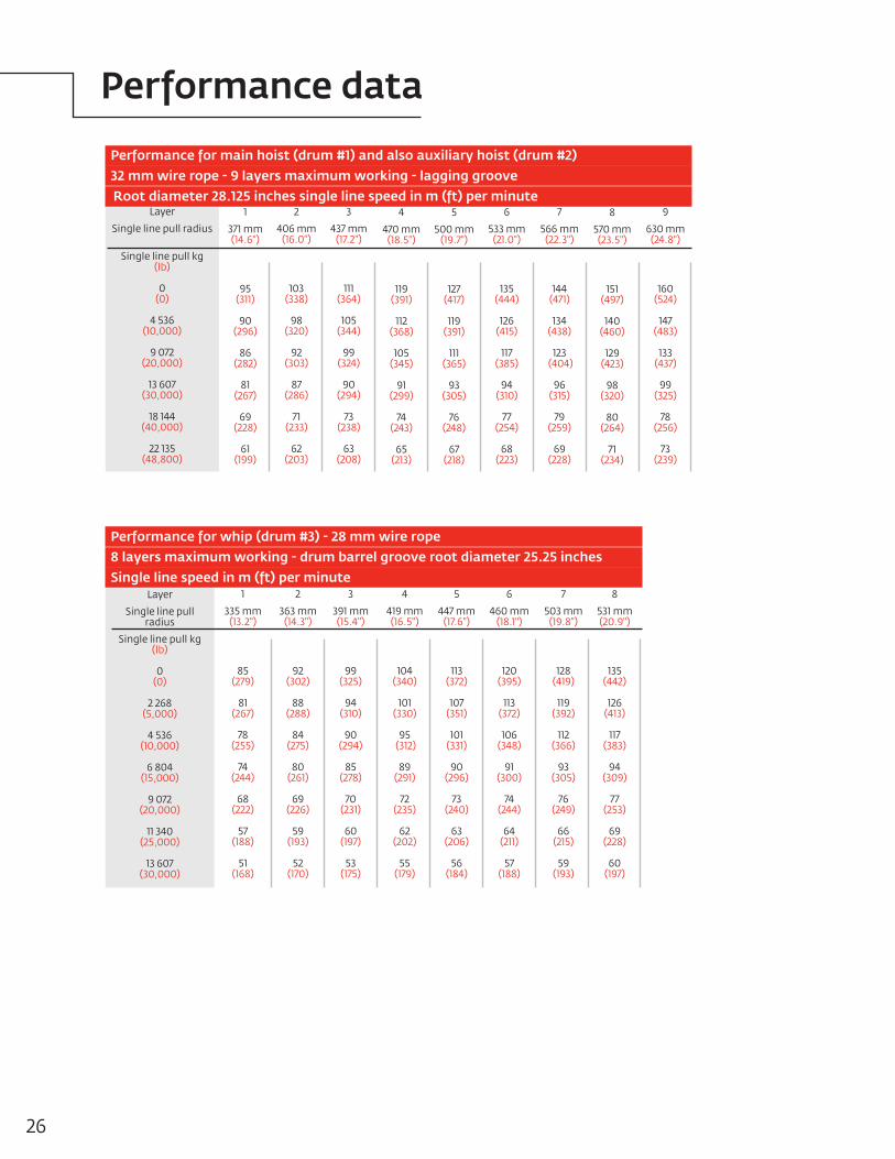
Performance for main hoist (drum #1) and also auxiliary hoist (drum #2) 32 mm wire rope - 9 layers maximum working - lagging groove Root diameter 28.125 inches single line speed in m (ft) per minute
9
630 mm(24.8")
160 (524)
147 (483)
133 (437)
99 (325)
78 (256)
73 (239)
1
371 mm (14.6")
95 (311)
90 (296)
86 (282)
81 (267)
69 (228)
61 (199)
2
406 mm(16.0")
103 (338)
98 (320)
92 (303)
87 (286)
71 (233)
62 (203)
3
437 mm(17.2")
111 (364)
105 (344)
99 (324)
90 (294)
73 (238)
63 (208)
4
470 mm (18.5")
119 (391)
112 (368)
105 (345)
91 (299)
74 (243)
65 (213)
5
500 mm(19.7")
127 (417)
119 (391)
111 (365)
93 (305)
76 (248)
67 (218)
6
533 mm (21.0")
135 (444)
126 (415)
117 (385)
94 (310)
77 (254)
68 (223)
7
566 mm(22.3")
144 (471)
134 (438)
123 (404)
96 (315)
79 (259)
69 (228)
8
570 mm(23.5")
151 (497)
140 (460)
129 (423)
98 (320)
80 (264)
71 (234)
Layer
Single line pull radius
Single line pull kg (lb)
0 (0)
2 268 (5,000)
4 536 (10,000)
6 804 (15,000)
9 072 (20,000)
11 340 (25,000)
13 607 (30,000)
Performance for whip (drum #3) - 28 mm wire rope 8 layers maximum working - drum barrel groove root diameter 25.25 inches Single line speed in m (ft) per minute
1
335 mm (13.2")
85 (279)
81 (267)
78 (255)
74 (244)
68 (222)
57 (188)
51 (168)
2
363 mm(14.3")
92 (302)
88 (288)
84 (275)
80 (261)
69 (226)
59 (193)
52 (170)
3
391 mm(15.4")
99 (325)
94 (310)
90 (294)
85 (278)
70 (231)
60 (197)
53 (175)
4
419 mm (16.5")
104(340)
101 (330)
95 (312)
89 (291)
72 (235)
62 (202)
55 (179)
5
447 mm(17.6")
113 (372)
107 (351)
101 (331)
90 (296)
73 (240)
63 (206)
56 (184)
6
460 mm (18.1")
120 (395)
113 (372)
106 (348)
91 (300)
74 (244)
64 (211)
57 (188)
7
503 mm(19.8")
128 (419)
119 (392)
112 (366)
93 (305)
76 (249)
66 (215)
59 (193)
8
531 mm(20.9")
135 (442)
126 (413)
117 (383)
94 (309)
77 (253)
69 (228)
60 (197)
26
Performance data

Model 18000 No. 55 or No. 55A
heavy-lift main boom 97,5 m (320 ft)
No. 55 or No. 55A heavy-lift boom
97,5 m (320 ft)
6,1 m (20 ft)No. 55 or boom butt
12,2 m (40 ft)No. 55 boom insert
12,2 m (40 ft)No. 55 boom insert
6,1 m (20 ft)No. 55 boom insert
12,2 m (40 ft)No. 55 boom insert
12,2 m (40 ft)No. 55 boom insert
9,1 m (30 ft)No. 55 or No. 55Aboom top
12,2 m (40 ft)No. 55 boom insert
3,0 m (10 ft)No. 55 boom insert
12,2 m (40 ft)No. 55 boom insert
NOTE: 36,6 m (120') basic boom consists of 6,1 m (20') butt, 3,0 m (10') insert with drum, 6,1 m (20') insert, 12,2 m (40'), and 9,1 m (30') top.
May use 12,2 m (40') No. 55 insert with or without sheaves.
Boom length m (ft)
36,6 (120)
42,7 (140)
48,8 (160)
54,9 (180)
61,0 (200)
67,1 (220)
73,2 (240)
79,2 (260)
85,3 (280)
91,4 (300)
97,5 (320)
6,1 m(20 ft)
1
–
1
2
1
2
1
2
1
2
1
12,2 m(40 ft)
1
2
2
2
3
3
4
4
5
5
6
Boom inserts
No. 55 or No. 55A boom combinations
3,0 m(10 ft)
1
1
1
1
1
1
1
1
1
1
1
Model 18000No. 79A fixed jib on
No. 55 or No. 55A heavy-lift main boom 88,0 m (290 ft)
No. 55 or No. 55A heavy-lift boom60,0 m (200 ft)
No. 79A fixed jib27,4 m (90 ft)
9,1 m (30 ft)No. 79A jib top
12,2 m (40 ft)No. 79 jib insert
12,2 m (40 ft)No. 55 boom insert
6,1 m 20 ft)No. 79 jib butt
6,1 m (20 ft)No. 55 boom butt
3,0 m (10 ft)No. 55 boom insert
6,1 m (20 ft)No. 55 boom insert
12,2 m (40 ft)No. 55 boom insert
12,2 m (40 ft)No. 55 boom insert
9,1 m (30 ft)No. 55 boom top
Fixed jibLength m (ft)
27,4 (50)
33,5 (70)
39,6 (90)
45,7 (110)
6,1 m(20 ft)
-
1
-
1
12,2 m(40 ft)
-
-
1
1
Fixed jib inserts
No. 79A fixed jib combinations
Manitowoc 18000 27
Boom combinations

Model 18000No. 55-79A
heavy-lift main boom 121,9 m (400 ft)
No. 55-79Aheavy-lift boom121,9 m (400 ft)
12,2 m (40 ft)No. 55 boom insert
6,1 m (20 ft)No. 55 boom butt
12,2 m (40 ft)No. 55-79 transition boom insert
12,2 m (40 ft)No. 79 boom insert
3,0 m (10 ft)No. 55 boom insert
6,1 m (20 ft)No. 55 boom insert
12,2 m (40 ft)No. 79 boom insert
12,2 m (40 ft)No. 79 boom insert
12,2 m (40 ft)No. 79 boom insert
9,1 m (30 ft)No. 79A boom top
12,2 m (40 ft)No. 79 boom insert
12,2 m (40 ft)No. 79 boom insert
12,2 m(40 ft)
–
–
–
–
1
1
2
2
3
3
4
4
5
5
6
12,2 m(40 ft)
1
1
1
1
1
1
1
1
1
1
1
1
1
1
1
Boom length m (ft)
36,6 (120)
42,7 (140)
48,8 (160)
54,9 (180)
61,0 (200)
67,1 (220)
73,2 (240)
79,2 (260)
85,3 (280)
91,4 (300)
97,5 (320)
103,6 (340)
109,7 (360)
115,8 (380)
121,9 (400)
6,1 m(20 ft)
1
–
1
1
1
1
1
1
1
1
1
1
1
1
1
12,2 m(40 ft)
–
1
1
1
1
1
1
1
1
1
1
1
1
1
1
6,1 m(20 ft)
–
–
–
1
–
1
–
1
–
1
–
1
–
1
–
No. 55-79A boom combinations
NOTE: 36,6 m (120') basic boom consists of 6,1 m (20') butt, 3,0 m (10') insert with drum, 6,1 m (20') insert, 12,2 m (40'), and 9,1 m (30') top.
May use 12,2 m (40') No. 55 insert with or without sheaves.
3,0 m(10 ft)
1
1
1
1
1
1
1
1
1
1
1
1
1
1
1
Boom inserts No. 55-79A 55* 79 transition
Model 18000 No. 55-79A heavy-lift main boom with
7,6 m (25 ft) extended upper boom point 121,9 m (400 ft)
No. 55-79Aheavy-lift boom121,9 m (400 ft)
12,2 m (40 ft)No. 55 boom insert
6,1 m (20 ft)No. 55 boom butt
12,2 m (40 ft)No. 55-79 transition boom insert
12,2 m (40 ft)No. 79 boom insert
3,0 m (10 ft)No. 55 boom insert
6,1 m (20 ft)No. 55 boom insert
12,2 m (40 ft)No. 79 boom insert
12,2 m (40 ft)No. 79 boom insert
12,2 m (40 ft)No. 79 boom insert
9,1 m (30 ft)No. 79A boom top
12,2 m (40 ft)No. 79 boom insert
12,2 m (40 ft)No. 79 boom insert
7,6 m (25 ft)Extended upper boom point
12,2 m(40 ft)
1
1
2
2
3
3
4
4
5
5
6
12,2 m(40 ft)
1
1
1
1
1
1
1
1
1
1
1
Boom length m (ft)
61,0 (200)
67,1 (220)
73,2 (240)
79,2 (260)
85,3 (280)
91,4 (300)
97,5 (320)
103,6 (340)
109,7 (360)
115,8 (380)
121,9 (400)
6,1 m(20 ft)
1
1
1
1
1
1
1
1
1
1
1
12,2 m(40 ft)
1
1
1
1
1
1
1
1
1
1
1
6,1 m(20 ft)
–
1
–
1
–
1
–
1
–
1
–
No. 55-79A boom combinations
NOTE: 36,6 m (120') basic boom consists of 6,1 m (20') butt, 3,0 m (10') insert with drum, 6,1 m (20') insert, 12,2 m (40'), and 9,1 m (30') top.
May use 12,2 m (40') No. 55 insert with or without sheaves.
3,0 m(10 ft)
1
1
1
1
1
1
1
1
1
1
1
Boom inserts No. 55-79A 55* 79 transition
28
Boom combinations

Luffingjib length
m (ft)
21,3 (70)
24,4 (80)
27,4 (90)
30,5 (100)
33,5 (110)
36,6 (120)
39,6 (130)
42,7 (140)
45,7 (150)
48,8 (160)
51,8 (170)
54,9 (180)
57,9 (190)
61,0 (200)
64,0 (210)
67,1 (220)
70,1 (230)
73,2 (240)
3,0 m (10 ft)
–
1
–
1
–
1
–
1
–
1
–
1
–
1
–
1
–
1
6,1 m(20 ft)
–
–
1
1
–
–
1
1
–
–
1
1
–
–
1
1
–
–
12,2 m(40 ft)
–
–
–
–
1
1
1
1
2
2
2
2
3
3
3
3
4
4
Luffing jib inserts
No. 44 luffing jib combinations
Model 18000No. 44 luffing jib on
No. 55-79A heavy-lift main boom 158,5 m (520 ft)
No. 55-79A heavy-lift boom85,3 m (280 ft)
No. 44 luffing jib73,2 m (240 ft)
12,2 m (40 ft)No. 44 jib insert
9,1 m (30 ft)No. 44 jib top
12,2 m (40 ft)No. 44 jib insert
12,2 m (40 ft)No. 44 jib butt
12,2 m (40 ft)No. 44 jib insert
12,2 m (40 ft)No. 55-79 boom insert
6,1 m (20 ft)No. 55 or No. 55A boom butt
12,2 m (40 ft)No 79 boom insert
12,2 m (40 ft)No. 79 boom insert
6,1 m (20 ft)No. 55 or No. 55A boom insert
3,0 m (10 ft)No. 55 or No. 55A boom insert
12,2 m (40 ft)No. 55 or No. 55A boom insert
12,2 m (40 ft)No. 79 boom insert
9,1 m (30 ft)No. 79A boom top
12,2 m (40 ft)No. 44 jib insert
3,0 m (10 ft)No. 44 jib insert
Model 18000No. 79A luffing jib on No. 55
or No. 55A heavy-lift main boom 149,3 m (490 ft)
No. 55 or No. 55A heavy-lift boom
54,9 m (180 ft)
No. 79A luffing jib94,5 m (310 ft)
12,2 m (40 ft)No. 79 jib insert
9,1 m (30 ft)No. 79A jib top
12,2 m (40 ft)No. 79 jib insert
12,2 m (40 ft)No. 79 jib insert
12,2 m (40 ft)No. 79 jib insert
12,2 m (40 ft)No. 55 boom insert
12,2 m (40 ft)No 55 boom insert
9,1 m (30 ft)No. 55 boom top
12,2 m (40 ft)No. 79 jib insert
12,2 m (40 ft)No. 79 jib insert
6,1 m (20 ft)No. 79A jib butt
3,0 m (10 ft)No. 79 jib insert
6,1 m (20 ft)No. 55 boom butt
3,0 m (10 ft)No. 55 Boom Insert
6,1 m (20 ft)No. 55 boom insert
6,1 m (20 ft)No. 55 boom insert
Luffingjib length
m (ft)
27,4 (90)
33,5 (110)
39,6 (130)
45,7 (150)
51,8 (170)
57,9 (190)
64,0 (210)
70,1 (230)
76,2 (250)
82,3 (270)
88,3 (290)
94,5 (310)
6,1 m(20 ft)
2
1
2
1
2
1
2
1
2
1
2
1
12,2 m(40 ft)
-
1
1
2
2
3
3
4
4
5
5
6
Luffing jib inserts
No. 79A luffing jib combinations
Manitowoc 18000 29
Boom combinations

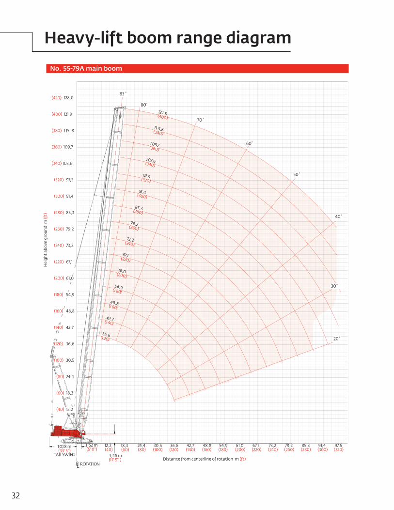
ROTATION
TAILSWING
1 0,1 8 m(33' 5")
3,46 m(1 1' 5" )
1,52 m(5' 0")
80 ⁰
70 ⁰
60 ⁰
50 ⁰
40 ⁰
83 ⁰
30 ⁰
20 ⁰
(40) 12,2
(200) 61,0
(220) 67,1
(240) 73,2
(260) 79,2
(280) 85,3
(300) 91,4
(320) 97,5
(340) 103,6
(180) 54,9
(160) 48,8
(140) 42,7
(120) 36,6
(100) 30,5
(80) 24,4
(60) 18,3
48,8(160)
54,9(180)
61,0(200)
67,1(220)
73,2(240)
42,7(140)
36,6(120)
30,5(100)
24,4(80)
18,3(60)
12,2(40)
79,2(260)
,97 5(320)
85,3(280)
48,8(1 60)
54,9(1 80)
36,6(1 20)
61,0(200)
42,7(1 40)
91,4(300)
73,2(240)
67,1(220)
79,2(260)
Hei
ght
abov
e gr
ound
m (f
t)
Distance from centerline of rotation m (ft)
No. 55 or No. 55A main boom
30
Heavy-lift boom range diagram

Meets ANSI B30.5 Requirements - Capacities do not exceed 75% of static tipping load.NOTICE: This capacity chart is for reference only and must not be used for lifting purposes.
Boomm (ft)
Radius 7,3 (24)
8,0 (26)
9,0 (30)
11,0 (36)
12,0 (40)
14,0 (45)
16,0 (50)
18,0 (60)
22,0 (70)
24,0 (80)
28,0 (90)
30,0 (100)
34,0 (110)
36,0 (120)
40,0 (130)
42,0 (140)
50,0(160)
54,0(180)
60,0(200)
66,0(220)
72,0(240)
76,0(250)
78,0(255)
36,6(120)
600,0 (1322.8)
512,8 (1145.7)
458,8 (995.9)
375,5 (830.1)
343,8 (745.8)
291,5 (657.7)
250,0 (583.2)
218,3 (472.6)
172,4 (394.4)
155,4 (336.3)
126,0 (286.3)
114,0 (245.7)
94,8 (213.5) 86,9 (187.1)
42,7(140)
457,5 (992.2)
373,9 (826.6)
342,3 (742.5) 290,3 (654.9)
248,8 (580.4)
217,0 (469.9)
171,3 (391.9)
154,3 (333.8)
125,3 (284.7)
113,3 (244.2)
94,1 (212.0)
86,3 (185.9)
73,3 (164.2)
67,8 (145.7)
48,8(160)
– (987.9)
372,1 (822.5)
340,4 (738.4) 288,7 (651.5)
247,2 (577.0)
215,5 (466.5)
169,8 (388.5)
152,8 (330.5)
124,2 (282.4)
112,2 (241.8)
93,1 (209.7)
85,3 (183.6)
72,3 (161.9)
66,8 (143.6)
– (114.2)
54,9(180)
370,5 (818.9)
338,8 (734.8) 287,3 (648.4)
245,8 (573.8)
214,0 (463.3)
168,3 (385.3)
151,3 (327.2)
123,2 (279.9) 111,1 (239.2)
91,8 (207.0)
84,1 (180.9)
71,1 (159.2)
65,6 (140.9)
48,3 (111.7)
41,7 (89.1)
48,2
61,0(200)
370,4 (816.7) 337,7 (732.6) 286,5 (646.6)
244,9 (572.0)
244,9 (461.5)
167,5 (383.4)
150,4 (325.9)
122,7 (278.9)
110,6 (238.1) 91,3 (205.8)
83,5 (179.6)
70,5 (157.9)
65,0 (139.6)
47,8 (110.4)
41,2 (88.1)
67,1(220)
336,1 (728.6) 285,0 (643.1)
243,3 (568.5)
211,6 (457.9)
165,8 (379.8)
148,8 (321.7)
121,5 (276.1)
109,3 (235.2)
89,9 (202.8) 82,1 (176.5)
69,1 (154.8)
63,5 (132.2)
46,3 (107.2)
39,8 (84.9)
31,6 (67.3)
73,2(240)
– (725.9) 283,9 (640.8)
242,3 (566.2)
210,5 (455.5)
164,7 (377.4)
147,7 (319.2)
120,7 (274.3)
108,4 (233.4)
89,1 (200.9)
81,2 (174.6) 68,2 (152.8)
62,7 (134.5)
45,4 (105.3)
38,9 (83.0)
30,7 (65.4)
21,3 (50.4)
Liftcrane boom capacities Boom No. 55 or No. 55A with 30,5 m (100 ft) mast No. 56 239 500 kg (528,000 lb) Counterweight 145 150 kg (320,000 lb) Carbody counterweight
360° Rating kg (lb) x 1 000
79,2(260)
282,5 (636.7)
240,6 (562.4)
208,8 (451.7)
163,0 (373.5)
145,9 (315.4)
119,1 (270.4)
107,1 (223.3)
87,6 (197.7)
79,7 (171.3) 66,7 (149.5)
61,1 (131.1)
43,9 (101.8)
37,3 (79.5)
29,2 (61.9) 22,3 (46.5)
15,6 (31.8)
11,6 (25.2) – (21.9)
85,4(280)
281,1 (633.7)
239,4 (559.8)
207,6 (449.0)
161,7 (368.7)
144,7 (312.6)
117,9 (267.6)
106,1 (228.1)
86,6 (195.5)
78,7 (169.0) 65,6 (147.1)
60,1 (128.7)
42,8 (99.4)
36,2 (77.1)
28,1 (59.5) 21,1 (43.8)
14,4 (29.4)
10,6 (23.0)
8,7 (19.9)
91,4(300)
238,4 (556.0)
205,8 (445.1)
159,9 (366.8)
142,9 (308.6)
116,2 (263.7)
104,7 (224.8)
85,1 (192.1)
77,2 (165.6) 64,0 (143.7)
58,5 (125.2)
41,1 (95.8)
36,6 (73.5)
26,4 (55.9) 19,0 (39.2)
12,4 (24.9)
8,6 (18.6)
– (15.6)
97,5(320)
236,3 (546.6)
206,1 (445.1)
160,0 (366.9)
142,9 (308.7)
116,2 (263.7)
104,9 (225.3)
85,3 (192.6)
77,4 (166.1) 64,2 (144.1)
58,7 (125.6)
41,3 (96.2)
34,7 (73.8)
26,6 (56.2)
19,3 (40.1)
12,8 (25.8)
– (19.5)
– (16.6)
Manitowoc 18000 31
Heavy-lift boom load charts
ROTATION
TAILSWING
1 0,1 8 m(33' 5")
3,46 m(1 1' 5" )
1,52 m(5' 0")
80 ⁰
70 ⁰
60 ⁰
50 ⁰
40 ⁰
30 ⁰
20 ⁰
83 ⁰
(40) 12,2
(200) 61,0
(220) 67,1
(240) 73,2
(260) 79,2
(280) 85,3
(300) 91,4
(320) 97,5
(340) 103,6
(360) 109,7
(380) 1 15, 8
(400) 121,9
(420) 128,0
(180) 54,9
(160) 48,8
(140) 42,7
(120) 36,6
(100) 30,5
(80) 24,4
(60) 18,3
48,8(160)
54,9(180)
61,0(200)
67,1(220)
73,2(240)
42,7(140)
36,6(120)
30,5(100)
24,4(80)
18,3(60)
12,2(40)
79,2(260)
85,3(280)
91,4(300)
97,5(320)
12 1,9(400)
97,5(320)
85,3(280)
1 03,6(340)
1 09,7(360)
11 5,8(380)
48,8(1 60)
54,9(1 80)
36,6(1 20)
61,0(200)
42,7(1 40)
91,4(300)
73,2(240)
67,1(220)
79,2(260)
Hei
ght
abov
e gr
ound
m (f
t)
Distance from centerline of rotation m (ft)
No. 55-79A main boom
32
Heavy-lift boom range diagram

Meets ANSI B30.5 Requirements - Capacities do not exceed 75% of static tipping load.NOTICE: This capacity chart is for reference only and must not be used for lifting purposes.
Boomm (ft)
Radius 7,9 (26)
9,1 (30)
10,0 (34)
12,0 (40)
14,0 (45)
16,0 (50)
18,0 (60)
20,0 (70)
24,0 (80)
26,0 (90)
30,0 (100)
36,0 (120)
42,0 (140)
48,0 (160)
54,0 (180)
60,0 (200)
66,0(220)
72,0(240)
78,0(260)
84,0(280)
88,0(300)
92,0(310)
96,0(320)
36,6 (120)
453,5 (1000.0)
453,5 (1000.0)
419,2 (891.6)
349,5 (758.5)
297,2 (670.2)
255,8 (595.8)
224,1 (485.5)
199,0 (407.6)
161,5 (349.7)
146,0 (299.2)
120,0 (258.9)
91,1 (192.1)
42,7 (140)
453,5 (1000.0)
417,7 (888.6)
348,2 (755.7)
296,2 (667.9) 254,8 (593.6)
223,1 (483.4)
198,0 (405.6)
160,6 (347.7)
145,6 (298.1)
119,5 (257.8)
92,7 (199.9)
74,2 (160.0)
48,8 (160)
426,0 (939.3)
416,0 (884.8)
346,6 (752.0)
294,8 (664.8) 253,4 (590.5)
221,8 (480.4)
196,6 (402.6)
159,3 (344.8)
144,7 (296.2)
118,6 (255.8)
91,7 (197.9)
73,4 (158.2)
59,9 (129.0)
61,0 (200)
340,7 (750.0)
294,2 (663.5) 252,8 (589.2)
221,2 (479.1)
196,1 (401.3)
158,7 (343.5)
144,4 (296.1)
118,5 (255.7) 91,6 (197.6)
73,3 (157.9)
59,9 (129.0)
49,7 (106.9)
67,1 (220)
309,8 (683.2)
287,1 (647.5) 251,4 (582.7)
220,6 (477.4)
195,3 (399.6)
157,9 (341.7)
143,6 (295.0)
118,0 (254.5)
91,1 (196.4) 72,7 (156.7)
59,3 (127.8)
49,2 (105.7)
41,1 (88.3)
73,2 (240)
– (633.7)
268,0 (599.8) 235,8 (543.9)
211,8 (460.5)
192,6 (398.8)
157,5 (340.9)
143,2 (294.7)
117,8 (254.1)
90,9 (195.9)
72,5 (56.2) 59,2 (127.3)
49,0 (105.3)
41,0 (88.0)
34,5 (73.8)
85,3 (280)
220,7 (488.0) 210,9 (481.2)
186,8 (406.1)
169,7 (352.8)
143,8 (312.6)
133,7 (280.9)
116,5 (251.8)
89,8 (193.5)
71,4 (153.7)
58,0 (124.8) 47,8 (102.8)
39,8 (85.5)
33,4 (71.4)
28,0 (59.8)
23,5 (50.0)
Liftcrane boom capacities - 18000 Boom No. 55-79A with 30,5 m (100 ft) mast No. 56 239 500 kg (528,000 lb) Counterweight 145 150 kg (320,000 lb) Carbody counterweight
360° Rating kg (lb) x 1 000
91,4 (300)
192,0 (430.5)
177,3 (383.4)
159,9 (332.2)
135,2 (293.8)
125,6 (263.7)
110,0 (239.2)
89,0 (190.7)
75,5 (151.8)
57,2 (122.9) 47,0 (100.9)
39,0 (83.6)
32,5 (69.6)
27,2 (58.0)
22,7 (48.2) 18,8 (39.8)
16,4
97,5 (320)
177,4 (397.5)
167,3 (364.3)
151,7 (314.8)
127,8 (277.8)
118,7 (248.9)
103,8 (225.5)
87,2 (189.4)
70,0 (150.7)
56,6 (12.7) 46,4 (99.7)
38,4 (82.4)
32,0 (68.4)
26,6 (56.8)
22,2 (47.1) 18,3 (38.7)
16,0 (30.6)
13,5 (26.3)
10,9 –
109,7 (360)
135,3 (298.3)
133,7 (282.8)
114,7 (249.0)
106,0 (221.8)
92,1 (199.9)
76,7 (166.5)
65,4 (141.9)
54,9 (118.0) 44,7 (95.9)
36,7 (78.6)
30,3 (64.6)
24,9 (53.1)
20,4 (43.3) 16,6 (35.0)
14,3 (26.6)
11,7 (22.6)
9,3 (18.7)
115,8 (380)
– (257.4)
116,0 (254.6)
109,5 (236.2)
100,3 (209.6)
86,8 (188.3)
71,9 (155.9)
60,9 (132.1)
52,4 (113.6) 43.,8 (93.8)
35,8 (76.5)
29,3 (62.5)
24,0 (50.9)
19,5 (41.2)
15,7 (332.9)
13,1 (24.1)
10,5 (20.0)
8,2 (16.2)
121,9 (400)
– (220.2)
99,8 (220.2)
99,5 (219.3)
95,6 (199.1)
82,1 (178.2)
67,6 (146.7)
57,0 (123.6)
48,9 (105.8) 42,2 (91.3)
35,1 (74.9)
28,6 (60.9)
23,2 (49.3)
18,8 (39.6)
14,9 (31.1)
12,2 (22.2)
9,7 –
7,4 –
Manitowoc 18000 33
Heavy-lift boom load charts

No. 55-79A main boom with 7,6 m (25 ft) extended upper boom point
ROTATION
TAILSWING
1 0,1 8 m(33' 5")
3,46 m(1 1' 5" )
1,52 m(5' 0")
80 ⁰
70 ⁰
60 ⁰
50 ⁰
40 ⁰
30 ⁰
20 ⁰
82.8 ⁰
(40) 12,2
(200) 61,0
(220) 67,1
(240) 73,2
(260) 79,2
(280) 85,3
(300) 91,4
(320) 97,5
(340) 103,6
(360) 109,7
(380) 1 15, 8
(400) 121,9
(420) 128,0
(180) 54,9
(160) 48,8
(140) 42,7
(120) 36,6
(100) 30,5
(80) 24,4
(60) 18,3
48,8(160)
54,9(180)
61,0(200)
67,1(220)
73,2(240)
42,7(140)
36,6(120)
30,5(100)
24,4(80)
18,3(60)
12,2(40)
79,2(260)
85,3(280)
91,4(300)
97,5(320)
12 1,9(400)
97,5(320)
85,3(280)
1 03,6(340)
1 09,7(360)
11 5,8(380)
61,0(200)
91,4(300)
73,2(240)
67,1(220)
79,2(260)
Hei
ght
abov
e gr
ound
m (f
t)
Distance from centerline of rotation m (ft)TTAILSWINAILSWINTTAILSWINTT GGAILSWINAILSWINGAILSWINAILSWIN
1 01 0,1,1 8 8 mm(33' 5")(33' 5")
11,52 ,52 mm(5' 0")(5' 0")
8080⁰⁰
85,385,3
88
54,954,9
48,848,8
36,636,6
,5,5
,4,4
(120)(120)3030,5,5(100)(100)
2424,4,4(80)(80)
18,318,3(60)(60)
12,12,22(40)(40)
1212121212121212 1,1,1,1,1,1,99999999(400)(400)(400)(400)(400)(400)(400)(400)(400)(400)(400)(400)(400)(400)(400)(400)
9797979797979797,5,5,5,5,5,5(320)(320)(320)(320)(320)(320)(320)(320)(320)(320)(320)(320)(320)(320)(320)(320)(320)(320)
85,385,385,385,385,385,385,385,385,385,3(280)(280)(280)(280)(280)(280)(280)(280)(280)(280)(280)(280)(280)(280)(280)(280)
111111 03,03,03,03,03,03,03,03,66666666(340)(340)(340)(340)(340)(340)(340)(340)(340)(340)(340)(340)(340)(340)(340)(340)(340)(340)(340)(340)
11111111 09,09,09,09,09,09,09,09,77777709,09,709,09,09,09,709,09,(360)(360)(360)(360)(360)(360)(360)(360)(360)(360)(360)(360)(360)(360)(360)(360)(360)(360)
1111111111111111 5,5,5,5,5,5,88888888(380)(380)(380)(380)(380)(380)(380)(380)(380)(380)(380)(380)(380)(380)(380)(380)
616161616161,0,0,0,0,0,0(200)(200)(200)(200)(200)(200)(200)(200)(200)(200)(200)(200)(200)(200)(200)(200)(200)(200)
91919191,4,4,4,4(300)(300)(300)(300)(300)(300)(300)(300)(300)(300)(300)(300)(300)(300)(300)(300)
73,73,73,73,73,73,73,73,2222(2(2(2(2(2(2(2(240)40)40)40)40)40)40)40)40)40)40)40)40)40)40)40)
6767676767676767,1,1,1,1,1,1(220)(220)(220)(220)(220)(220)(220)(220)(220)(220)(220)(220)(220)(220)(220)(220)(220)(220)
79,79,79,79,79,79,79,79,222222(260)(260)(260)(260)(260)(260)(260)(260)(260)(260)(260)(260)(260)(260)(260)(260)
Hei
ght
abov
e gr
Hei
ght
abov
e gr
ound
m
ound
m (f
t)(f
t)
(40) 12,2
(200) 61,0
(220) 67,1
(240) 73,2
(260) 79,2
(280) 85,3
(300) 91,4
(320) 97,5
(340) 103,6
(360) 109,7
(380) 1 15, 8
(400) 121,9
(420) 128,0
(180) 54,9
(160) 48,8
(140) 42,7
(120) 36,6
(100) 30,5
(80) 24,4
(60) 18,3
Hei
ght
abov
e gr
ound
m (f
t)Extended upper boom point range diagram
34

Meets ANSI B30.5 Requirements - Capacities do not exceed 75% of static tipping load.NOTICE: This capacity chart is for reference only and must not be used for lifting purposes.
Boomm (ft)
Radius 15,2 (50)
16,0 (55)
18,0 (60)
20,0 (65)
22,0 (70)
24,0 (80)
26,0 (85)
30,0(100)
32,0 (105)
34,0 (110)
36,0(120)
38,0 (125)
40,0(130)
42,0 (140)
46,0 (150)
50,0(165)
54,0(175)
58,0(190)
62,0(205)
68,0(225)
74,0(240)
86,0(280)
98,0(320)
61,0(200)
132,8 (292.8)
132,8 (292.8)
132,8 (292.8)
132,8 (292.8)
132,8 (292.8)
132,8 (292.8)
132,8 (292.8)
123,6 (265.3)
112,5 (248.0)
103,3 (232.4)
95,4 (205.8)
88,4 (194.3)
82,2 (183.7) 76,6 (165.1)
67,1 (149.3)
59,1 (129.3)
52,5 (118.0)
46,7 (103.4)
–(30.5)
73,2(240)
132,8 (292.8)
132,8 (292.8)
132,8 (292.8)
132,8 (292.8)
132,8 (292.8)
122,8 (263.6)
111,7 (246.3)
102,5 (230.7)
94,6 (204.0)
87,6 (192.4)
81,3 (181.8)
75,7 (163.2)
66,2 (147.3)
58,3 (127.4)
51,6 (116.1)
45,9 (101.6)
41,0 (89.3)
34,7 (75.4)
– (17.1)
85.3(280)
132,8 (292.8)
132,8 (292.8)
132,8 (292.8)
129,5 (286.3)
114,0 (248.0)
107,6 (237.4)
101,5 (227.6)
93,5 (201.6)
86,5 (190.0)
80,2 (179.4)
74,6 (160.7)
65,0 (144.7)
57,1 (124.8)
50,4 (113.5)
44,7 (99.0)
39,8 (86.7)
33,6 (72.9)
28,4 (64.2)
97.5(320)
132,7 (292.8)
131,6 (291.9)
124,9 (270.1)
115,5 (255.5)
101,2 (220.0)
95,4 (210.3)
90,1 (201.4)
85,4 (185.7)
81,2 (178.6)
77,3 (172.0)
73,2 (157.8)
63,7 (141.8)
55,7 (121.7)
49,0 (110.5)
43,3 (95.9)
38,4 (83.6)
32,2 (69.9)
27,0 (61.2)
18,8 (42.5)
109,7(360)
99,9 (220.9)
99,3 (218.7)
98,6 (217.7)
89,2 (194.0)
84,1 (185.6)
79,7 (178.0)
75,6 (164.3)
71,9 (158.2)
68,6 (152.6)
65,4 (142.2)
59,7 (132.5)
54,1 (118.1)
47,3 (106.7)
41,6 (92.1)
36,7 (79.8)
30,5 (66.1)
25,3 (57.3)
17,1 (38.7)
10,0 (22.7)
121,9(400)
76,2 (167.8)
75,6 (166.9)
74,7 (164.5)
74,2 (163.7)
72,8 (162.2)
68,4 (148.5)
64,8 (142.6)
61,3 (136.7)
58,2 (126.2)
52,6 (116.8)
47,7 (104.6)
43,5 (97.4)
39,6 (87.7)
35,1 (76.2)
28,8 (62.5)
23,6 (53.7)
15,5 (35.1) 8,0 (18.3)
Liftcrane boom capacities - Model 18000 Boom No. 55-79A main boom with 7,6 m (25 ft) extended upper boom point 239 500 kg (528,000 lb) Counterweight 145 150 kg (320,000 lb) Carbody counterweight
360° Rating kg (lb) x 1 000
Manitowoc 18000 35
Extended upper boom point load chart

ROTATION
TAILSWING
10,18 m(33' 5")
3,46 m(11' 5")
1,52 m(5' 0")
(40) 1 2,2
(200) 61,0
(220) 67,1
(240) 73,2
(260) 79,2
(280) 85,3
(300) 91,4
(320) 97,5
(1 80) 54,9
(1 60) 48,8
(1 40) 42,7
(1 20) 36,6
(1 00) 30,5
(80) 24,4
(60) 1 8,3
(30) 9,1
(1 90) 57,9
(21 0) 64,0
(230) 70,1
(250) 76,2
(270) 82,3
(290) 88,4
(31 0) 94,5
(1 70) 51,8
(1 50) 45,7
(1 30) 39,6
(11 0) 33,5
(90) 27,4
(70) 21,3
(50) 1 5,2
48,8(1 60)
54,9(1 80)
61,0(200)
67,1(220)
73,2(240)
42,7(1 40)
36,6(1 20)
30,5(1 00)
24,4(80)
1 8,3(60)
1 2,2(40)
79,2(260)
82 ⁰
70 ⁰
60 ⁰
50 ⁰
40 ⁰
30 ⁰
20 ⁰
80 ⁰
20 ⁰
5 ⁰
33,5(110)
27,4(90)
21,3(70)
15,2(50)
88,4(290)
64,0(210)
76,2(250)
70,1(230)
82,3(270)
57,9(190)
Hei
ght
abov
e gr
ound
m (f
t)
Distance from centerline of rotation m (ft)
No. 79A fixed Jib No. 79A with 15,2 m (50 ft) strut on boom No. 55 or 55A with 30,5 m (100 ft) mast No. 56
36
Fixed jib range diagram
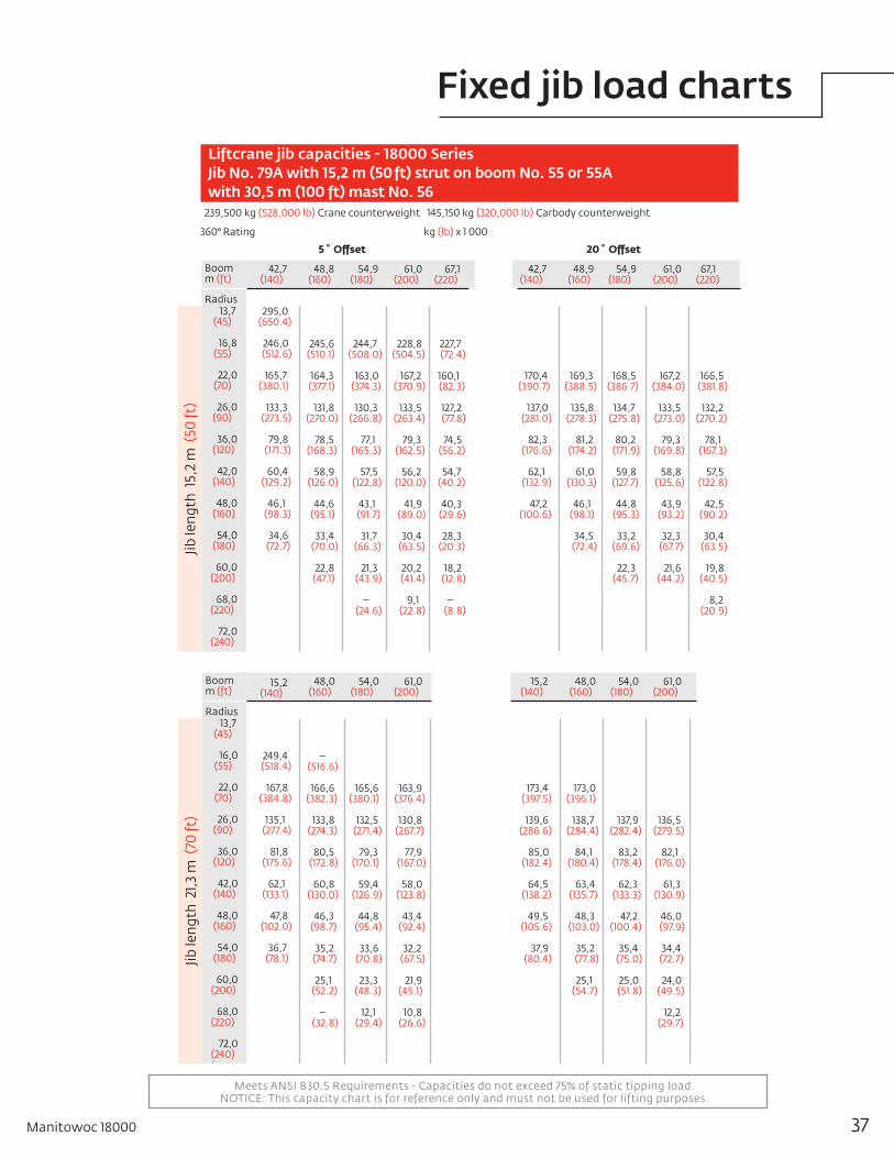
Meets ANSI B30.5 Requirements - Capacities do not exceed 75% of static tipping load.NOTICE: This capacity chart is for reference only and must not be used for lifting purposes.
Liftcrane jib capacities - 18000 Series Jib No. 79A with 15,2 m (50 ft) strut on boom No. 55 or 55A with 30,5 m (100 ft) mast No. 56239,500 kg (528,000 lb) Crane counterweight 145,150 kg (320,000 lb) Carbody counterweight
360° Rating kg (lb) x 1 000
5˚Offset 20˚Offset
42,7 (140)
295,0 (650.4)
246,0 (512.6)
165,7 (380.1)
133,3 (273.5)
79,8 (171.3)
60,4 (129.2)
46,1 (98.3)
34,6 (72.7)
48,8 (160)
245,6 (510.1)
164,3 (377.1)
131,8 (270.0) 78,5 (168.3)
58,9 (126.0)
44,6 (95.1)
33,4 (70.0)
22,8 (47.1)
54,9 (180)
244,7 (508.0)
163,0 (374.3)
130,3 (266.8) 77,1 (165.3)
57,5 (122.8)
43,1 (91.7)
31,7 (66.3)
21,3 (43.9)
– (24.6)
61,0 (200)
228,8 (504.5)
167,2 (370.9)
133,5 (263.4) 79,3 (162.5)
56,2 (120.0)
41,9 (89.0)
30,4 (63.5)
20,2 (41.4)
9,1 (22.8)
67,1 (220)
227,7 (72.4)
160,1 (82.3)
127,2 (77.8) 74,5 (56.2)
54,7 (40.2)
40,3 (29.6)
28,3 (20.3)
18,2 (12.8)
– (8.8)
42,7 (140)
170,4 (390.7)
137,0 (281.0)
82,3 (176.6)
62,1 (132.9)
47,2 (100.6)
48,9 (160)
169,3 (388.5)
135,8 (278.3) 81,2 (174.2)
61,0 (130.3)
46,1 (98.1)
34,5 (72.4)
54,9 (180)
168,5 (386.7)
134,7 (275.8) 80,2 (171.9)
59,8 (127.7)
44,8 (95.3)
33,2 (69.6)
22,3 (45.7)
61,0 (200)
167,2 (384.0)
133,5 (273.0) 79,3 (169.8)
58,8 (125.6)
43,9 (93.2)
32,3 (67.7)
21,6 (44.2)
67,1 (220)
166,5 (381.8)
132,2 (270.2) 78,1 (167.3)
57,5 (122.8)
42,5 (90.2)
30,4 (63.5)
19,8 (40.5)
8,2 (20.9)
Boomm (ft)
Radius 13,7 (45)
16,8 (55)
22,0 (70)
26,0 (90)
36,0 (120)
42,0 (140)
48,0 (160)
54,0 (180)
60,0 (200)
68,0 (220)
72,0 (240)
Jib le
ngth
15,
2 m
(50
ft)
15,2 (140)
249,4 (518.4)
167,8 (384.8)
135,1 (277.4)
81,8 (175.6)
62,1 (133.1)
47,8 (102.0)
36,7 (78.1)
48,0 (160)
– (516.6)
166,6 (382.3)
133,8 (274.3) 80,5 (172.8)
60,8 (130.0)
46,3 (98.7)
35,2 (74.7)
25,1 (52.2)
– (32.8)
54,0 (180)
165,6 (380.1)
132,5 (271.4) 79,3 (170.1)
59,4 (126.9)
44,8 (95.4)
33,6 (70.8)
23,3 (48.3)
12,1 (29.4)
61,0 (200)
163,9 (376.4)
130,8 (267.7) 77,9 (167.0)
58,0 (123.8)
43,4 (92.4)
32,2 (67.5)
21,9 (45.1)
10,8 (26.6)
15,2 (140)
173,4 (397.5)
139,6 (286.6)
85,0 (182.4)
64,5 (138.2)
49,5 (105.6)
37,9 (80.4)
48,0 (160)
173,0 (396.1)
138,7 (284.4) 84,1 (180.4)
63,4 (135.7)
48,3 (103.0)
35,2 (77.8)
25,1 (54.7)
54,0 (180)
137,9 (282.4) 83,2 (178.4)
62,3 (133.3)
47,2 (100.4)
35,4 (75.0)
25,0 (51.8)
61,0 (200)
136,5 (279.5) 82,1 (176.0)
61,3 (130.9)
46,0 (97.9)
34,4 (72.7)
24,0 (49.5)
12,2 (29.7)
Boomm (ft)
Radius 13,7 (45)
16,0 (55)
22,0 (70)
26,0 (90)
36,0 (120)
42,0 (140)
48,0 (160)
54,0 (180)
60,0 (200)
68,0 (220)
72,0 (240)
Jib le
ngth
21,3
m (
70 ft
)
Manitowoc 18000 37
Fixed jib load charts

Meets ANSI B30.5 Requirements - Capacities do not exceed 75% of static tipping load.NOTICE: This capacity chart is for reference only and must not be used for lifting purposes.
Liftcrane jib capacities - 18000 series Jib No. 79A with 15,2 m (50 ft) strut on boom No. 55 or 55A with 30,5 m (100 ft) mast No. 56113 040 kg (249,200 lb) Crane counterweight 54 430 kg (120,000 lb) Carbody counterweight
360° Rating kg (lb) x 1 000
5˚Offset 20˚Offset
42,7 (140)
– (520.8)
168,7 (386.8)
135,9 (279.0)
82,9 (178.0)
63,1 (135.3)
48,7 (104.1)
37,7 (80.2)
28,1 (58.9)
16,7 (39.8)
48,8 (160)
167,7(384.7)
134,7(276.2)
81,7
(175.3)
61,8(132.2)
47,2(100.8)
36,2(76.8)
26,4(55.1)
15,3(36.5)
10,4(20.0)
54,9 (180)
166,8 (382.9)
133,6 (273.6) 80,6 (172.8)
60,4 (129.3)
45,8 (97.6)
34,6 (73.4)
24,6 (51.0)
13,5 (32.4)
8,7 (16.4)
61,0 (200)
165,0 (370.9)
131,8 (269.7) 79,0 (169.4)
58,9 (125.9)
44,3 (94.2)
33,0 (69.3)
22,8 (47.3)
11,8 (28.8)
42,7 (140)
141,2 (289.9)
86,8 (186.3)
66,1 (141.7)
51,1 (109.0)
37,7 (83.9)
28,1 (62.3)
16,7 –
48,9 (160)
141,2 (288.2) 86,8 (184.5)
66,1 (139.4)
51,1 (106.4)
39,4 (81.1)
28,5 (59.5)
16,5 (39.3)
54,9 (180)
139,9 (286.6) 85,3 (182.9)
64,2 (137.3)
48,8 (103.9)
37,0 (78.4)
27,0 (56.2)
15,0 (36.1)
9,9 (18.8)
61,0 (200)
138,5 (283.6) 84,1 (180.3)
63,0 (134.6)
47,5 (101.2)
35,8 (75.7)
25,7 (53.3)
13,9 (33.5)
8,8 (16.6)
Boomm (ft)
Radius 13,7 (45)
16,0 (55)
22,0 (70)
26,0 (90)
36,0 (120)
42,0 (140)
48,0 (160)
54,0 (180)
60,0 (200)
68,0 (220)
72,0 (240)
Jib le
ngth
27,
4 m
(90
ft)
42,7 (140)
169,2 (387.8)
136,4 (280.2)
83,8 (180.0)
64,1 (137.4)
49,7 (106.3)
38,7 (82.5)
29,7 (62.4)
18,8 (44.1)
48,8 (160)
168,3 (386.1)
135,3 (277.6)
82,7 (177.5)
62,7 (134.4)
48,2 (103.0)
37,2 (79.1)
27,9 (58.4)
17,0 (40.1)
8,0 (17.4)
54,9 (180)
167,9 (384.6)
134,3 (275.3) 81,7 (175.2)
61,5 (131.6)
46,9 (99.9)
35,7 (75.7)
26,0 (54.2)
15,0 (35.7)
42,7 (140)
142,3 (292.5)
88,3 (189.6)
67,6 (145.0)
52,6 (112.3)
41,0 (87.3)
31,8 (67.3)
20,3 (47.6)
48,8 (160)
141,9 (291.2) 87,6 (188.1)
66,7 (142.9)
51,5 (109.9)
39,8 (84.5)
30,5 (64.2)
17,0 (44.6)
8,0 –
54,9 (180)
– (290.1) 87,1 (186.9)
65,9 (141.0)
50,4 (107.5)
38,6 (81.9)
29,1 (60.9)
17,3 (41.1)
7,7 (16.5)
Boomm (ft)
Radius 13,7 (45)
16,0 (55)
22,0 (70)
26,0 (90)
36,0 (120)
42,0 (140)
48,0 (160)
54,0 (180)
60,0 (200)
68,0 (220)
76,0 (250)
Jib le
ngth
33,
5 m
(11
0 ft
)
38
Fixed jib load charts

ROTATION
TAILSWIN G
10,18 m(33' 5")
3,46 m(11' 5")
1,52 m(5' 0")
Hei
ght
abov
e gr
ound
m (f
t)
Distance from centerline of rotation m (ft)
80 ⁰
70⁰
87 ⁰
75 ⁰
70 ⁰
50 ⁰
75 ⁰
60 ⁰
30 ⁰
40 ⁰
20 ⁰
85 ⁰
10 ⁰
(40) 12,2
(200) 61,0
(220) 67,1
(240) 73,2
(260) 79,2
(280) 85,3
(300) 91,4
(320) 97,5
(340)103,6
(360) 109,7
(380) 115,8
(400) 121,9
(420) 128,0
(180) 54,9
(160) 48,8
(140) 42,7
(120) 36,6
(100) 30,5
(80) 24,4
(60) 18,3
(440) 134,1
(460) 140,2
(480) 146,3
(500) 152,4
(520) 158,5
48,8(160)
54,9(180)
61,0(200)
67,1(220)
73,2(240)
42,7(140)
36,6(120)
30,5(100)
24,4(80)
18,3(60)
12,2(40)
79,2(260)
85,3(280)
91,4(300)
97,5(320)
103,6(340)
48,8(160)
54,9(180)
61,0(200)
88,4(290)
94,5(310)
76,2(250)
82,3(270)
51,8(170)
57,9(190)
64,0(210)
45,7(150)
39,6(130)
33,5(110)
70,1(230)
27,4(90)
No. 79A luffing jib on No. 55 or No. 55A main boom
Manitowoc 18000 39
Luffing jib range diagram

Meets ANSI B30.5 Requirements - Capacities do not exceed 75% of static tipping load.NOTICE: This capacity chart is for reference only and must not be used for lifting purposes.
Liftcrane luffing jib capacities - 18000 Luffing jib No. 79A on boom No. 55 or No. 55A with 30,5 m (100 ft) mast No. 56 239 500 kg (528,000 lb) Counterweight 145 150 kg (320,000 lb) Carbody counterweight
360° Rating
87˚Boomangle 61,0 (200)
225,3 (537.4)
200,3 (488.0)
180,1 (411.0)
163,2 (353.5)
149,0 (308.8)
126,0 (272.8)
Boomm (ft)
Radius 16,0 (55)
18,0 (60)
20,0 (70)
24,0 (80)
26,0 (90)
30,0 (100)
36,0 (120)
42,0 (140)
48,0(160)
54,0(180)
60,0(200)
Luffi
ng ji
b le
ngth
26,
0 m
(90
ft)
61,0(200)
– (527.7)
224,3 (486.9)
199,9 (410.1)
162,9 (352.9)
148,8 (308.6)
126,1 (273.1)
101,5 (219.5)
Boomm (ft)
Radius 16,0
(55)
18,0 (60)
20,0 (70)
24,0 (80)
26,0 (90)
30,0 (100)
36,0 (120)
42,0 (140)
48,0(160)
54,0(180)
60,0(200)
Luffi
ng ji
b le
ngth
33,
5 m
(11
0 ft
)
61,0 (200)
176,5 (380.4)
160,9 (348.8)
146,9 (304.7)
124,5 (269.6)
100,3 (217.0)
82,7 (178.4)
68,4 (140.7)
Boomm (ft)
Radius 16,0 (55)
18,0 (60)
20,0 (70)
24,0 (80)
26,0 (90)
30,0 (100)
36,0 (120)
42,0 (140)
48,0(160)
54,0(180)
Luffi
ng ji
b le
ngth
45,
7 m
(15
0 ft
)
61,0 (200)
131,8 (289.2)
127,9 (275.3)
119,1 (260.2)
98,3 (212.6)
81,0 (175.0)
67,1 (144.7)
56,4 (121.5)
47,8 (102.8)
Boomm (ft)
Radius 16,0 (55)
18,0 (60)
20,0 (70)
24,0 (80)
26,0 (90)
30,0 (100)
36,0 (120)
42,0 (140)
48,0(160)
54,0(180)
Luffi
ng ji
b le
ngth
57,
9 m
(19
0 ft
)
40
Luffing jib load charts

Meets ANSI B30.5 Requirements - Capacities do not exceed 75% of static tipping load.NOTICE: This capacity chart is for reference only and must not be used for lifting purposes.
Liftcrane luffing jib capacities - 18000 Luffing jib No. 79A on boom No. 55 or No. 55A with 30,5 m (100 ft) mast No. 56 239 500 kg (529,007 lb) Counterweight 145 150 kg (320,000 lb) Carbody counterweight
360° Rating
85˚Boomangle
48,8 (160)
240,7(530.7)
222,8(482.0)
197,9 (406.0)
161,2(349.2)
147,2(305.1)
124,6 (269.6)
54,9(180)
– (478.0)
196,2(402.6)
159,9 (346.3)
145,9(302.6)
123,5 (267.4)
61,0(200)
225,3 (474.1)
200,3(399.3)
163,2(343.5)
149,0(300.1)
126,0(265.3)
–(223.2)
Boomm (ft)
Radius 16,8(55)
18,0(60)
20,0(70)
24,0(80)
26,0(90)
30,0 (100)
34,0 (115)
42,0(140)
44,0(150)
46,0(155)
Luffi
ng ji
b le
ngth
27,
4 m
(90
ft)
Luffi
ng ji
b le
ngth
36,
9 m
(13
0 ft
)
48,8(160)
– (402.0)
159,6(345.7)
145,7(302.2)
123,5 (267.4)
106,5 (226.6)
80,8(174.4)
75,6(157.6)
54,9(180)
180,7(398.4)
158,2
(342.6) 144,4(299.4)
122,3 (264.9)
105,5 (224.4)
80,4(173.5)
75,3 (157.0)
61,0(200)
–
(394.9)
156,7 (339.5)
143,1 (296.7)
121,2 (262.5)
104,6 (222.4)
80,0
(172.5)
74,9 (156.2)
70,1 (148.4)
Boomm (ft)
Radius 16,8(55)
18,0(60)
20,0(70)
24,0(80)
26,0(90)
30,0(100)
34,0(115)
42,0(140)
44,0(150)
46,0(155)
48,8 (160)
132,5(271.7)
118,2(255.5)
94,3(204.0)
63,2(136.2)
44,7(96.0)
34,2(75.2)
29,0
(63.7)
54,9 (180)
114,6(252.7)
93,3(201.7)
62,7(135.2)
44,3(95.2)
33,9(74.6)
28,8(63.2)
Boomm (ft)
Radius
29,0 (95)
30,5 (100)
36,0 (120)
48,0 (160)
60,0 (200)
70,0(230)
76,0(250)
82,0(270)
88,0(290)
100,0 (330)
Luffi
ng ji
b le
ngth
70,
1 m (
230
ft)
48,8(160)
– (153.0)
58,9(126.7)
40,4(86.7)
29,9 (65.7)
24,6 (53.9)
–(43.8)
16,1(35.0)
9,2(19.7)
54,9(180)
58,4
(125.5)
40,0(85.7)
29,1 (64.0)
23,9 (52.4)
–(42.4)
15,5(33.7)
8,7
(18.7)
Boomm (ft)
Radius
29,0 (95)
30,5 (100)
36,0 (120)
48,0 (160)
60,0 (200)
70,0 (230)
76,0 (250)
82,0 (270)
88,0 (290)
100,0 (330)
Luffi
ng ji
b le
ngth
94,
5 m
(31
0 ft
)
Manitowoc 18000 41
Luffing jib load charts
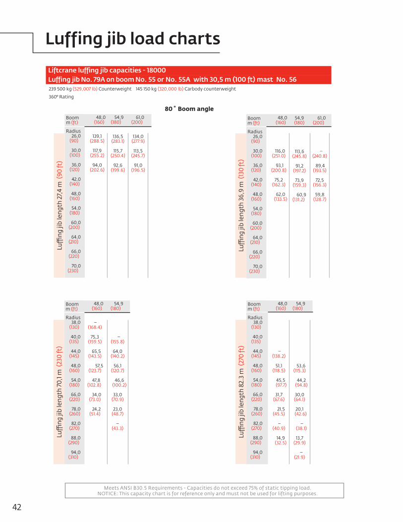
Meets ANSI B30.5 Requirements - Capacities do not exceed 75% of static tipping load.NOTICE: This capacity chart is for reference only and must not be used for lifting purposes.
Liftcrane luffing jib capacities - 18000 Luffing jib No. 79A on boom No. 55 or No. 55A with 30,5 m (100 ft) mast No. 56 239 500 kg (529,007 lb) Counterweight 145 150 kg (320,000 lb) Carbody counterweight
360° Rating
80˚Boomangle 48,0 (160)
139,1(288.5)
117,9(255.2)
94,0(202.6)
54,9 (180)
136,5(283.1)
115,7(250.4)
92,6(199.6)
61,0 (200)
134,0(277.9)
113,5 (245.7)
91,0(196.5)
Boomm (ft)
Radius 26,0 (90)
30,0 (100)
36,0 (120)
42,0 (140)
48,0 (160)
54,0 (180)
60,0 (200)
64,0 (210)
66,0 (220)
70,0(230)
Luffi
ng ji
b le
ngth
27,
4 m
(90
ft)
48,0 (160)
116,0 (251.0)
93,1 (200.8)
75,2(162.3)
62,0(133.5)
54,9(180)
113,6(245.8)
91,2
(197.2)
73,9(159.3) 60,9(131.2)
61,0 (200)
– (240.8)
89,4(193.5)
72,5(156.3)
59,8(128.7)
Boomm (ft)
Radius 26,0 (90)
30,0 (100)
36,0 (120)
42,0 (140)
48,0 (160)
54,0 (180)
60,0 (200)
64,0 (210)
66,0(220) 70,0(230)
Luffi
ng ji
b le
ngth
36,
9 m
(13
0 ft
)
48,0 (160)
–(168.4)
75,3(159.5)
65,5 (143.5)
57,5(123.7)
47,8(102.8)
34,0 (73.0)
24,2
(51.4)
54,9 (180)
– (155.8)
64,0(140.2)
56,1(120.7)
46,6(100.2)
33,0(70.9)
23,0(48.7)
–(43.3)
Boomm (ft)
Radius 38,0 (130)
40,0 (135)
44,0 (145)
48,0 (160)
54,0 (180)
66,0 (220)
78,0 (260)
82,0 (270)
88,0 (290)
94,0 (310)
Luffi
ng ji
b le
ngth
70,
1 m (
230
ft)
48,0 (160)
– (138.2)
51,1(118.5)
45,5 (97.7)
31,7(67.6)
21,5 (45.5)
–(40.9)
14,9(32.5)
54,9 (180)
53,6(115.3)
44,2(94.8)
30,0(64.1)
20,1 (42.6)
–(38.1)
13,7(29.9)
–(21.9)
Boomm (ft)
Radius 38,0 (130)
40,0 (135)
44,0 (145)
48,0 (160)
54,0 (180)
66,0 (220)
78,0 (260)
82,0 (270)
88,0 (290)
94,0 (310)
Luffi
ng ji
b le
ngth
82.
3 m
(27
0 ft
)
42
Luffing jib load charts
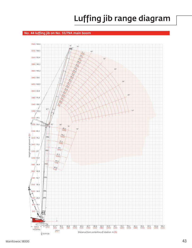
ROTATION
TAILSWING
1 0,1 8 m(33' 5")
3,46 m(1 1' 5" )
1,52 m(5' 0")
48,8(160)
54,9(180)
61,0(200)
67,1(220)
73,2(240)
42,7(140)
36,6(120)
30,5(100)
24,4(80)
18,3(60)
12,2(40)
79,2(260)
85,3(280)
91,4(300)
97,5(320)
103,6(340)
109,7(360)
80⁰
70 ⁰
75 ⁰
70 ⁰
50⁰
75⁰
60⁰
30⁰
40⁰
20 ⁰
85 ⁰
1 0⁰87 0
85,3(280)
48,8(1 60)
54,9(1 80)
61,0(200)
73,2(240)
67,1(220)
79,2(260)(260) 79,2
(420) 128,0
(440) 134,1
(460) 140,2
(480) 146,3
(500) 152,4
(520) 158,5
(540) 164,6
(400) 121,9
(380) 115,8
(360) 109,7
(340) 103,6
(320) 97,5
(300) 91,4
(280) 85,3
(200) 61,0
(240) 73,2
(220) 67,1
(140) 42,7
(180) 54,9
(160) 48,8
(80) 24,4
(120) 36,6
(100) 30,5
(60) 18,3
(40) 12,2
51,8(170)
57,9(190)
64,0(210)
45,7(150)
39,6(130)
33,5(110)
48,8(160)
30,5(100)
54,9(180)
36,6(120)
61,0(200)
42,7(140)
70,1(230)
24,4(80)
27,4(90)
21,3(70)
73,2(240)
67,1(220)
Hei
ght
abov
e gr
ound
m (f
t)
Distance from centerline of rotation m (ft)
No. 44 luffing jib on No. 55/79A main boom
Manitowoc 18000 43
Luffing jib range diagram
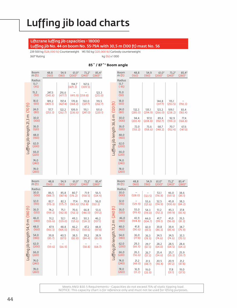
Meets ANSI B30.5 Requirements - Capacities do not exceed 75% of static tipping load.NOTICE: This capacity chart is for reference only and must not be used for lifting purposes.
Liftcrane luffing jib capacities - 18000 Luffing jib No. 44 on boom No. 55-79A with 30,5 m (100 ft) mast No. 56 239 500 kg (528,000 lb) Counterweight 145 150 kg (320,000 lb) Carbody counterweight
360° Rating kg (lb) x 1 000
85˚/87˚*Boomangle
48,8 (160)
132,3 (285.0)
94,4 (203.4)
72,0 (155.2)
54,9 (180)
135,1 (294.9)
97,0 (208.8)
73,6 (158.6)
61,0* (200)*
(( 87
144,8 (317.7) 123,2 (266.0)
89,4 (192.7)
68,7 (148.2)
73,2* (240)*
115,1 (253.5) 109,1 (238.2)
92,9 (199.3)
70,7 (152.4)
85,4* (280)*
– (192.3) 83,4 (183.4)
77,4 (168.8)
67,6 (147.0)
Boomm (ft)
Radius 13,7 ( 45)
15,0 (50)
18,0 (60)
24,0 (80)
30,0 (100)
36,0 (120)
48,0 (160)
62,0(200)
66,0(220)
74,0(240)
78,0(260)
Luffi
ng ji
b le
ngth
36,
6 m
(12
0 ft
)
48,8(160)
247,5 (545.8)
189,2 (405.1)
117,7 (253.3)
54,9 (180)
216,6 (477.7)
197,4 (427.4) 122,2 (262.7)
61,0* (200)*
194,7 (429.3) (( 87 – (415.9)
170,8 (368.2) 109,9 (236.6)
73,2* (240)*
167,6 (369.5)
– (359.8) 150,0 (327.7) 115,1 (247.0)
85,4* (280)*
123,3(272.0)
119,5
(262.7)
101,0(220.1)
Boomm (ft)
Radius 13,7 ( 45)
15,2 (50)
18,0 (60)
24,0 (80)
30,0 (100)
36,0 (120)
48,0 (160)
62,0(200)
66,0(220)
74,0(240)
78,0(260)
Luffi
ng ji
b le
ngth
21,3
m (
70 ft
)
48,8 (160)
86,5 (188.7)
82,7 (176.3)
74,2 (159.3)
51,2 (126.6)
47,9 (103.3)
39,8 (85.7)
– (59.6)
54,9 (180)
85,8 (187.4)
82,3 (175.7)
75,1 (162.8) 52,1 (129.0)
48,8 (105.0)
40,5 (87.1)
– (66.9)
61,0* (200)*
80,7 (176.2) (( 87 77,4 (165.6)
70,6 (152.3) 49,3 (121.6)
46,2 (99.6)
38,5 (82.8)
73,2* (240)*
71,9 (158.5)
70,8 (152.8) 66,8 (146.0) 50,3 (124.3)
47,2 (101.6)
39,2 (84.4)
– (58.8)
85,4* (280)*
56,5 (124.4)
56,0 (122.3) 53,6 (117.2) 46,2 (107.1)
44,8 (97.8)
38,9 (83.9)
– (68.7)
Boomm (ft)
Radius 30,0 ( 100)
32,0 (110)
36,0 (120)
46,0 (140)
48,0 (160)
54,0 (180)
62,0 (200)
66,0(220)
74,0(240)
78,0 (260)
Luffi
ng ji
b le
ngth
54,
9 m
(18
0 ft
)
48,8(160)
– (128.0)
– (125.9)
55,0 (119.8)
43,9 (104.8)
41,8 (90.6)
36,0 (77.8)
29,3 (66.5)
26,3 (56.6)
21,2 (48.0)
16,9 (31.2)
54,9 (180)
–(123.5)
55,6(121.6)
54,3(119.0)
44,0
(104.7)
42,0(91.1)
36,3(78.5)
29,7(67.3)
26,7(57.3)
21,5(48.7)
19,0(35.9)
61,0*(200)*
53,1 (116.8)
(( 52,5
(114.9)
51,2(112.3)
41,7
(99.1)
39,8(86.3)
34,5(74.6)
28,2(64.0)
25,4(54.6)
20,5 (46.4)
73,2*(240)*
46,0(101.5)
45,8(100.6)
45,3
(99.9)
41,0(96.8)
39,4(85.4)
34,5(74.6)
28,5(64.5)
25,7(55.3)
20,9(47.2)
17,8(31.1)
85,4* (280)*
38,6(85.1)
38,3(84.2)
37,8
(83.4)
35,5(81.3)
34,7(75.9)
32,3(70.5)
28,4(64.3)
25,9(55.7)
21,2(47.8)
19,0(37.5)
Boomm (ft)
Radius 30,0 ( 100)
32,0 (110)
36,0 (120)
46,0 (140)
48,0 (160)
54,0 (180)
62,0 (200)
66,0(220)
74,0(240)
78,0 (260)
Luffi
ng ji
b le
ngth
73,
2 m
(24
0 ft
)
44
Luffing jib load charts

Meets ANSI B30.5 Requirements - Capacities do not exceed 75% of static tipping load.NOTICE: This capacity chart is for reference only and must not be used for lifting purposes.
Liftcrane luffing jib capacities - 18000 Luffing jib No. 44 on boom No. 55-79A with 30,5 m (100 ft) mast No. 56 239 500 kg (528,000 lb) Counterweight 145 150 kg (320,000 lb) Carbody counterweight
360° Rating kg (lb) x 1 000
80˚Boomangle
48,8(160)
–
(194.8)
83,8(182.6)
69,3(148.9)
55,5(119.4)
45,6(98.0)
35,9(81.7)
54,9 (180)
84,2(183.7)
72,5(155.2)
57,6
(123.8)
47,2(101.3)
37,0(84.3)
61,0 (200)
(( 87
84,1(183.5)
74,7(162.0)
59,8
(128.5)
48,8(104.8)
38,2(86.9)
73,2 (240)
66,7 (144.2)
56,3
(121.7)
48,2(104.1)
39,8 (90.0)
34,0 (65.2)
85,4 (280)
56,4 (123.7)
48,0
(103.8)
40,9(88.3)
33,5(75.9)
29,0(60.9)
Boomm (ft)
Radius – ( 110)
36,0 (120)
42,0 (140)
48,0 (160)
54,0 (180)
62,0 (200)
68,0 (230)
78,0 (260)
84,0 (280)
88,0 (290)
Luffi
ng ji
b le
ngth
54,
9 m
(18
0 ft
)
48,8(160)
53,2
(115.7)
46,7(101.1)
40,4(87.4)
33,1(75.0)
28,3(59.1)
21,7(46.3)
54,9 (180)
53,0(116.3)
47,2
(102.5)
41,3(89.2)
33,9(76.9)
29,1(60.8)
22,3(47.7)
18,6(30.0)
61,0 (200)
(( 87
–(111.1)
47,6
(103.5)
41,9 (90.7)
34,7 (78.5)
29,8 (62.4)
23,0
(49.1)
19,5 (41.1)
73,2 (240)
44,0(97.1)
42,7(92.5)
36,0(81.3)
31,2(65.5)
24,3
(51.9)
20,8(44.3)
17,3(36.1)
85,4 (280)
37,1(82.0)
37,1(81.8)
31,0(70.3)
26,7(56.1)
21,0(45.1)
18,2(38.9)
16,5(36.0)
Boomm (ft)
Radius – ( 110) 36,0 (120)
42,0 (140)
48,0 (160)
54,0 (180)
62,0 (200)
68,0 (230)
78,0 (260)
84,0 (280)
88,0 (290)
Luffi
ng ji
b le
ngth
73,
2 m
(24
0 ft
)
48,8 (160)
– (405.8)
178,3 (376.7)
160,9 (347.6)
138,9 (276.7)
106,2 (227.5)
90,6 –
54,9 (180)
– (401.2)
176,3 (372.5)
160,2 (347.3) 146,8 (298.7)
113,6 (243.2)
100,4 (173.3)
61,0 (200)
(( 87 – (368.1)
158,0 (341.9) 144,1 (298.6)
121,1 (260.9)
107,3 (215.7)
73,2 (240)
– (296.4) 124,8 (258.6)
105,5 (228.4)
97,7 (203.7)
84,2 (181.8)
85,4 (280)
– (227.2)
92,7 (200.6)
85,8 (178.7)
74,1 (160.2)
Boomm (ft)
Radius 20,0 ( 70)
22,0 (75)
24,0 (80)
26,0 (90)
30,0 (100)
32,0 (110)
36,0 (120)
42.0 (140)
48,0 (160)
50,0 (170)
Luffi
ng ji
b le
ngth
21,3
m (
70 ft
)
48,8(160)
145,1(305.8)
119,9(256.6)
106,8(217.4)
87,3(187.6)
67,5(145.0)
54,9 (180)
–
(302.0)
124,2 (269.1)
113,3(229.7)
91,8(197.1)
70,5(151.3)
53,2(104.3)
61,0(200)
(( 87
120,1(259.9)
111,4(232.6)
96,4(207.5)
73,6(157.9)
58,1(124.4)
73,2 (240)
– (223.3)
95,6(199.5)
83,0(179.7)
68,8(148.8)
58,0(125.3)
54,9(114.8)
85,4 (280)
82,1(173.5)
72,1(156.1)
59,5(128.7)
50,0(108.1)
47,3(99.3)
Boomm (ft)
Radius 20,0 ( 70)
22,0 (75)
24,0 (80)
26,0 (90)
30,0 (100)
32,0 (110)
36,0 (120)
42,0 (140)
48,0 (160)
50,0 (170)
Luffi
ng ji
b le
ngth
36,
6 m
(12
0 ft
)
Manitowoc 18000 45
Luffing jib load charts

Meets ANSI B30.5 Requirements - Capacities do not exceed 75% of static tipping load.NOTICE: This capacity chart is for reference only and must not be used for lifting purposes.
48,8(160)
107,3 (236.6)
99,4 (210.9)
92,4 (199.8)
54,9 (180)
– (205.7)
90,2 (194.9) 73,8 (159.3)
61,0 (200)
(( 87
– (190.2) 72,2 (156.1)
73,2 (240)
68,0(147.0)
57,0(122.9)
85,4 (280)
52,5(113.5)
49,7(104.3)
Boomm (ft)
Radius 32,0 ( 105)
34,0 (115)
36,0 (120)
42,0 (140)
48,0 (160)
50,0 (170)
54,0 (180)
62,0(200)
64,0(210)
66,0(220)
Luffi
ng ji
b le
ngth
21,3
m (
70 ft
) Liftcrane luffing jib capacities - 18000 Luffing jib No. 44 on boom No. 55-79A with 30,5 m (100 ft) Mast No. 56 239 500 kg (528,000 lb) Counterweight 145 150 kg (320,000 lb) Carbody counterweight
360° Rating kg (lb) x 1 000
70˚Boomangle
48,8(160)
74,8(161.7)
63,1(136.3)
59,8(125.9)
54,0(116.5)
54,9 (180)
–(157.0)
61,2(132.4)
58,1(122.4)
52,5(113.4)
61,0 (200)
(( 87
59,5(128.7)
56,5(118.9)
51,1(110.3)
73,2 (240)
–(119.8)
52,6(110.7)
47,5(102.6)
39,3(88.9)
37,4(82.6)
85,4 (280)
42,4 (91.5)
34,9 (78.9)
33,2 (73.4)
31,7 (68.2)
Boomm (ft)
Radius 32,0 ( 105)
34,0 (115)
36,0 (120)
42,0 (140)
48,0 (160)
50,0 (170)
54,0 (180)
62,0 (200)
64,0(210)
66,0(220)
Luffi
ng ji
b le
ngth
36,
6 m
(12
0 ft
)
48,8(160)
–
(122.9)
52,8(114.1)
43,9(99.2)
40,3(87.1)
–(73.2)
54,9 (180)
–(118.9)
51,1(110.3)
42,5(95.9)
39,0(84.1)
33,0(74.2)
61,0 (200)
(( 87
– (106.8)
41,1(92.7)
37,7
(81.3)
31,9(71.7)
73,2 (240)
37,8 (85.4)
34,6(74.7)
29,3(65.9)
27,1(58.2)
85,4 (280)
29,4(63.4)
24,5(55.2)
22,4(48.2)
19,6(41.8)
Boomm (ft)
Radius 50,0 ( 170)
54,0 (180)
62,0 (200)
66,0 (220)
74,0 (240)
78,0 (260)
84,0 (280)
90,0 (300)
96,0(320)
104,0 (340)
Luffi
ng ji
b le
ngth
54,
9 m
(18
0 ft
)
48,8(160)
40,7(92.0)
37,1(79.8)
30,4(68.6)
27,4(58.6)
23,4(50.0)
20,0(42.4)
54,9 (180)
37,0(79.9)
31,3(70.4)
28,9(61.9)
24,8(52.9)
21,2(45.0)
61,0 (200)
(( 87
35,6(76.9)
30,1(67.7)
27,8(59.9)
24,7(53.3)
22,1(47.4)
19,1–
73,2 (240)
27,3(61.3)
25,1(54.1)
22,3(47.9)
19,8(42.5)
17,6(37.7)
85,4 (280)
21,4(48.4)
19,5(41.8)
16,8(36.1)
14,6(31.1)
12,5(26.6)
10,0(22.4)
Boomm (ft)
Radius 50,0 ( 170)
54,0 (180)
62,0 (200)
66,0 (220)
74,0 (240)
78,0 (260)
84,0 (280)
90,0(300)
96,0(320)
104,0 (340)
Luffi
ng ji
b le
ngth
73,
2 m
(24
0 ft
)
46
Luffing jib load charts

9,14 m (30' 0")
2,45 m (8' 1")
Rotation
A1 or A
2
A1 = 1 PIECE SHEAR FRAME 12,19 m (40' 0")
A2 = 2 PIECE SHEAR FRAME 17,98 m (59' 0")
WHEELED COUNTERWEIGHT (ONE PIECE SHEAR FRAME FOR 40' RADIUS SHOWN.)
B1 = 1 PIECE SHEAR FRAME TAILSWING 14,55 m (47' 9")
B2 = 2 PIECE SHEAR FRAME TAILSWING 20,16 m (66' 2")
C1 = 1 PIECE SHEAR FRAME TAILSWING 14,66 m (48' 1")
C2 = 2 PIECE SHEAR FRAME TAILSWING 20,44 m (67' 1")
B1 or B
2
C1 or C
2
47Manitowoc 18000
Outline dimensionsMAX-ER®

Wheeled carrier with tires x 1Length 9,27 m 30' 5"Width 3,55 m 11' 8"Height 3,55 m 11' 8"Weight 43 252 kg 95,355 lb
Wheeled carrier without tires x 1Length 9,27 m 30' 5"Width 3,30 m 10' 10"Height 3,55 m 11' 8"Weight 17 872 kg 39,400 lb
Counterweight tray x 1Length 9,14 m 30' 0"Width 2,71 m 8' 11"Height 1,03 m 3' 5"Weight 15 381 kg 33,910 lb
A-Frame x 2Length 2,38 m 7' 10"Width 0,92 m 3' 1"Height 2,87 m 9' 5"Weight 3 807 kg 8,395 lb
Center counterweight box x 4Length 3,56 m 11' 8"Width 1,24 m 4' 10"Height 0,93 m 3' 1"Weight 19 958 kg 44,000 lb
Side counterweight box x 12Length 3,56 m 11' 8"Width 2,59 m 8' 6"Height 0,50 m 1' 8"Weight 19 958 kg 44,000 lb
WL
H
L
H
W
W
L
H
W
L
H
L
H
W
48
Outline dimensionsMAX-ER®
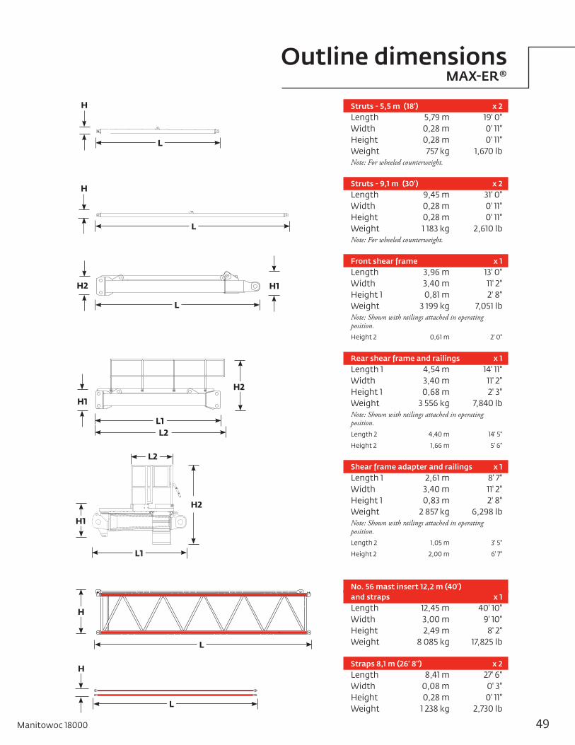
Struts - 5,5 m (18') x 2Length 5,79 m 19' 0"Width 0,28 m 0' 11"Height 0,28 m 0' 11" Weight 757 kg 1,670 lbNote: For wheeled counterweight.
Struts - 9,1 m (30') x 2Length 9,45 m 31' 0"Width 0,28 m 0' 11"Height 0,28 m 0' 11"Weight 1 183 kg 2,610 lbNote: For wheeled counterweight.
Front shear frame x 1Length 3,96 m 13' 0"Width 3,40 m 11' 2"Height 1 0,81 m 2' 8"Weight 3 199 kg 7,051 lbNote: Shown with railings attached in operating position.Height 2 0,61 m 2' 0"
Rear shear frame and railings x 1Length 1 4,54 m 14' 11"Width 3,40 m 11' 2"Height 1 0,68 m 2' 3"Weight 3 556 kg 7,840 lbNote: Shown with railings attached in operating position.Length 2 4,40 m 14' 5"
Height 2 1,66 m 5' 6"
Shear frame adapter and railings x 1Length 1 2,61 m 8' 7"Width 3,40 m 11' 2"Height 1 0,83 m 2' 8"Weight 2 857 kg 6,298 lbNote: Shown with railings attached in operating position.Length 2 1,05 m 3' 5"
Height 2 2,00 m 6' 7"
No. 56 mast insert 12,2 m (40')and straps x 1Length 12,45 m 40' 10"Width 3,00 m 9' 10"Height 2,49 m 8' 2"Weight 8 085 kg 17,825 lb
Straps 8,1 m (26' 8") x 2Length 8,41 m 27' 6"Width 0,08 m 0' 3"Height 0,28 m 0' 11"Weight 1 238 kg 2,730 lb
L
H
L
H
L
H
L1
L2
H2
H1
L
H
L
H1H2
H1
H2
L1L2
49Manitowoc 18000
Outline dimensionsMAX-ER®
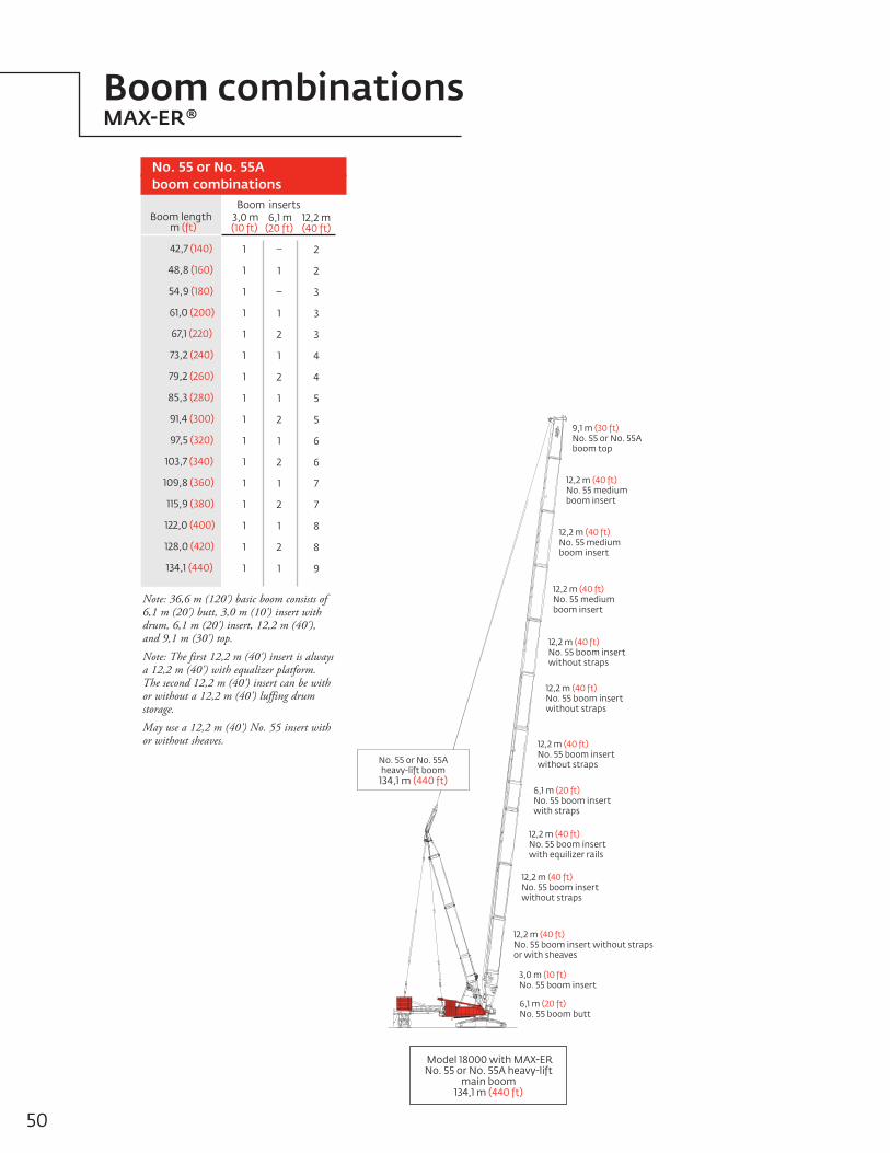
Model 18000 with MAX-ER No. 55 or No. 55A heavy-lift
main boom 134,1 m (440 ft)
No. 55 or No. 55A heavy-lift boom
134,1 m (440 ft)
6,1 m (20 ft)No. 55 boom butt
12,2 m (40 ft)No. 55 boom insert with equilizer rails
6,1 m (20 ft)No. 55 boom insertwith straps
9,1 m (30 ft)No. 55 or No. 55Aboom top
12,2 m (40 ft)No. 55 boom insert without strapsor with sheaves
3,0 m (10 ft)No. 55 boom insert
12,2 m (40 ft)No. 55 mediumboom insert
12,2 m (40 ft)No. 55 boom insertwithout straps
12,2 m (40 ft)No. 55 boom insertwithout straps
12,2 m (40 ft)No. 55 boom insert without straps
12,2 m (40 ft)No. 55 boom insert without straps
12,2 m (40 ft)No. 55 mediumboom insert
12,2 m (40 ft)No. 55 mediumboom insert
Note: 36,6 m (120') basic boom consists of 6,1 m (20') butt, 3,0 m (10') insert with drum, 6,1 m (20') insert, 12,2 m (40'), and 9,1 m (30') top.
Note: The first 12,2 m (40') insert is always a 12,2 m (40') with equalizer platform. The second 12,2 m (40') insert can be with or without a 12,2 m (40') luffing drum storage.
May use a 12,2 m (40') No. 55 insert with or without sheaves.
Boom length m (ft)
42,7 (140)
48,8 (160)
54,9 (180)
61,0 (200)
67,1 (220)
73,2 (240)
79,2 (260)
85,3 (280)
91,4 (300)
97,5 (320)
103,7 (340)
109,8 (360)
115,9 (380)
122,0 (400)
128,0 (420)
134,1 (440)
6,1 m(20 ft)
–
1
–
1
2
1
2
1
2
1
2
1
2
1
2
1
12,2 m(40 ft)
2
2
3
3
3
4
4
5
5
6
6
7
7
8
8
9
3,0 m(10 ft)
1
1
1
1
1
1
1
1
1
1
1
1
1
1
1
1
No. 55 or No. 55A boom combinations
Boom inserts
Boom combinationsMAX-ER®
50

Model 18000 with MAX-ERNo. 79A luffing jib on
No. 55 or No. 55A heavy-lift main boom 185,9 m (610 ft)
No. 55 or No. 55A heavy-lift boom
91,4 m (300 ft)
No. 79A luffing jib94,5 m (310 ft)
9,1 m (30 ft)No. 79A jib top
12,2 m (40 ft)No. 55 boom insert
12,2 m (40 ft)No 55 boom insert
12,2 m (40 ft)No. 79 jib insert
6,1 m (20 ft)No. 79A jib butt
6,1 m (20 ft)No. 55 boom butt
3,0 m (10 ft)No. 55 boom insert
6,1 m (20 ft)No. 55 boom insert
6,1 m (20 ft)No. 55 boom insert
12,2 m (40 ft)No. 79 jib insert
12,2 m (40 ft)No. 79 jib insert
12,2 m (40 ft)No. 79 jib insert
12,2 m (40 ft)No. 79 jib insert
12,2 m (40 ft)No. 79 jib insert
6,1 m (20 ft)No. 79 jib insert
9,1 m (30 ft)No. 55 boom top
12,2 m (40 ft)No. 79 boom insert
12,2 m (40 ft)No. 55 mediumboom insert
12,2 m (40 ft)No 55 boom insert
Luffingjib length
m (ft)
27,4 (50)
33,5 (70)
39,6 (90)
45,7 (110)
6,1 m(20 ft)
-
1
-
1
12,2 m(40 ft)
-
-
1
1
Fixed jib inserts
No. 79A fixed jib combinations
Model 18000 with MAX-ERNo. 79A fixed jib on
No. 55 or No. 55A heavy-lift main boom 137,2 m (450 ft)
No. 55 or No. 55A heavy-lift boom103,7 m (340 ft)
No. 79A fixed jib33,5 m (110 ft)
9,1 m (30 ft)No. 79A jib top
12,2 m (40 ft)No. 79 jib insert
12,2 m (40 ft)No. 55 boom insert
6,1 m (20 ft)No. 79 jib insert
6,1 m (20 ft)No. 55 boom butt
3,0 m (10 ft)No. 55 boom insert
6,1 m (20 ft)No. 55 boom insert
12,2 m (40 ft)No. 55 boom insert
12,2 m (40 ft)No. 55 boom insert
9,1 m (30 ft)No. 55 boom top
6,1 m (20 ft)No. 79A jib butt
12,2 m (40 ft)No. 55 boom insert
6,1 m (20 ft)No. 55 boom insert
12,2 m (40 ft)No. 55 medium boom insert
12,2 m (40 ft)No. 55 boom insert
Luffingjib length
m (ft)
27,4 (90)
33,5 (110)
39,6 (130)
45,7 (150)
51,8 (170)
57,9 (190)
64,0 (210)
70,1 (230)
76,2 (250)
82,3 (270)
88,3 (290)
94,5 (310)
6,1 m(20 ft)
1
–
1
–
1
–
1
–
1
–
1
–
12,2 m(40 ft)
–
1
1
2
2
3
3
4
4
5
5
6
Luffing jib inserts
No. 79A luffing jib combinations
Note: 21,3 m (70') basic boom consists of 6,1 m (20') butt, 6,1 m (20') insert with drum, and 9,1 m (30') top.
Boom combinationsMAX-ER®
51Manitowoc 18000

ROTATION
TAILSWING
1 8,00 m(59' 0")
3,46 m(1 1' 5" )
1,52 m(5' 0")
83 ⁰
80 ⁰
70 ⁰
60 ⁰
50 ⁰
40 ⁰
30 ⁰
20 ⁰
(40) 12,2
(200) 61,0
(220) 67,1
(240) 73,2
(260) 79,2
(280) 85,3
(300) 91,4
(320) 97,5
(340) 103,6
(360) 109,7
(380) 1 15, 8
(400) 121,9
(420) 128,0
(180) 54,9
(160) 48,8
(140) 42,7
(120) 36,6
(100) 30,5
(80) 24,4
(60) 18,3
(440) 134,1
(460) 140,2
48,8(160)
54,9(180)
61,0(200)
67,1(220)
73,2(240)
42,7(140)
36,6(120)
30,5(100)
24,4(80)
18,3(60)
12,2(40)
79,2(260)
85,3(280)
91,4(300)
97,5(320)
103,6(340)
109,7(360)
1 15, 8(380)
121,9(400)
128,0(420)
1 21,9(400)
97,5(320)
85,3(280)
1 03,6(340)
1 09,7(360)
1 1 5,8(380)
48,8(1 60)
54,9(1 80)
6 ,0(200)
42,7(1 40)
91,4(300)
73,2(240)
67,1(220)
79,2(260)
1 34,1(440)
1 28,0(420)
Hei
ght
abov
e gr
ound
m (f
t)
Distance from centerline of rotation m (ft)
No. 55 or No. 55A main boom
52
Heavy-lift boom range diagram MAX-ER®

Meets ANSI B30.5 Requirements - Capacities do not exceed 75% of static tipping load.NOTICE: This capacity chart is for reference only and must not be used for lifting purposes.
Boomm (ft)
Radius 8,5 (28)
10,0 (34)
12,0 (40)
14,0 (50)
18,0 (60)
20,0 (70)
24,0 (80)
30,0 (100)
36,0 (120)
42,0 (140)
48,0 (160)
54,0 (180)
66,0 (220)
72,0 (240)
78,0 (260)
84,0 (280)
90,0 (300)
96,0 (320)
102,0 (340)
108,0 (360)
114,0 (380)
130,0 (430)
42,7 (140)
750,0 (1653.5)
750,0 (1653.5)
715,7 (1543.3)
649,9 (1310.1)
502,1 (1089.4)
450,8 (929.9)
373,1 (809.2)
294,5 (638.4)
233,1 (502.2)
181,4 (387.5)
54,9 (180)
684,81509.8)
684,8 1509.8)
647,9 1303.8)
499,3 1083.3) 448,0 (923.9)
370,4 (803.3)
291,9 (632.8)
239,1 (518.0)
201,0 (435.4)
167,5 (359.6)
134,5 (285.7)
67,1 (220)
570,9 (1258.0)
565,8 (1240.2) 497,8 (1075.8)
444,6 (916.3) 367,0 (795.7)
288,5 (625.2)
235,6 (510.4)
197,6 (427.7)
168,9 (365.4)
146,4 (316.6)
79,2 (260)
405,6 (894.4)
405,6 ( 894.4) 405,6 ( 894.4)
364,8 (789.4)
285,6 (618.9)
232,8 (504.2)
194,8 (421.6)
166,1 (359.3) 143,7 (310.6)
– (237.2)
– (197.2)
91,4 (300)
– (655,0)
297,1 ( 655,0)
297,1 ( 655,0)
297,1 ( 655,0)
284,2 (612.1)
229,7 (497.4)
191,8 (414.9)
163,1 (352.6) 140,7 (304.0)
– (232.7)
– (205.8)
82,7 (175.8)
– (145.6)
– –
103,6 (340)
223,1 (491.9) 223,1 ( 491.9) 223,1 ( 491.9)
223,1 ( 491.9)
223,1 ( 491.9)
189,9 (410.9)
161,3 (348.7)
138,9 (300.1)
106,2 (229.0) – (202.1)
83,3 (179.3)
– (157.4)
62,3 (131.6)
– (107.9)
115,8 (380)
– (374.2)
169,7 ( 374.2)
169,7 ( 374.2)
169,7 ( 374.2)
169,5 (373.7)
167,2 (368.2)
159,4 (343.7)
136,6 (295.1)
103,9 (224.0) – (197.2)
81,1 (174.5)
– (154.9)
64,2 (137.8)
– (115.2)
45,3 (94.8)
– (75.6)
18000 MAX-ER®
Boom No. 55 or No. 55A , with 42,7 m (140 ft) No. 56 mast with 18 m (59 ft) position 223 170 kg (492,000 lb) Counterweight 145 150 kg (320,000 lb) Carbody counterweight
390 090 kg (860,000 lb) Wheeled counterweight or 391 810 kg (863,800 lb) hanging counterweight
360° Rating kg (lb) x 1 000
134,0 (440)
117,2 (258.5)
117,2 ( 258.5)
117,2 ( 258.5) 116,4 (256.5)
115,1 (253.4)
113,6 (250.1)
112,0 (246.5) 110,3 (216.2)
– (189.4)
77,6 (166.7)
– (147.2)
60,7 (130.2) – (115.3)
47,4 (99.6)
– (81.6)
31,7 (65.3)
13,9 (28.0)
53Manitowoc 18000
Heavy-lift boom load charts MAX-ER®

Meets ANSI B30.5 Requirements - Capacities do not exceed 75% of static tipping load.NOTICE: This capacity chart is for reference only and must not be used for lifting purposes.
Boomm (ft)
Radius 8,5 (28)
10,0 (34)
12,0 (40)
14,0 (50)
18,0 (60)
20,0 (70)
24,0 (80)
30,0 (100)
36,0 (120)
42,0 (140)
48,0 (160)
54,0 (180)
66,0 (220)
72,0 (240)
78,0 (260)
84,0 (280)
90,0 (300)
96,0 (320)
102,0 (340)
108,0 (360)
114,0 (380)
130,0 (430)
42,7 (140)
750,0 (1653.5)
729,8 (1543.3)
614,4 (1333.6)
526,7 (1066.1)
407,8 (884.7)
365,7 (753.6)
299,3 (646.1)
222,7 (480.4)
171,3 (368.6)
131,4 (280.0)
54,9 (180)
684,8 1509.8)
611,4 1327.0)
523,81059.8)
405,0 (878.6) 362,9 (747.6)
299,1 (648.4)
234,6 (508.3)
189,2 (407.2)
149,8 (322.1)
119,9 (256.9)
94,7 (199.7)
67,1 (220)
570,9 (1258.0)
522,6 (1052.4) 401,6 (871.1)
359,5 (740.0) 295,7 (640.9)
231,1 (500.7)
187,7 (406.3)
156,4 (338.3)
128,7 (276.3)
104,6 (223.9)
79,2 (260)
405,6 (894.4)
394,8 (864.8) 356,7 (733.8)
292,8 (634.6)
228,3 (494.4)
184,8 (400.1)
153,6 (332.1)
130,0 (280.9) 110,8 (237.1)
74,3 (158.1)
– (127.1)
91,4 (300)
– (655,0)
297,1 (655,0)
297,1 (655,0)
287,8 (627.8)
225,2 (487.6)
181,8 (393.3)
150,5 (325.4)
126,9 (274.2) 108,5 (234.2)
77,4 (165.0)
– (134.6)
51,5 (108.5)
– (85.1)
– –
103,6 (340)
223,1 (491.9) 223,1 (491.9) 223,1 (491.9)
220,5 (483.6)
180,0 (389.3)
148,7 (321.5)
125,2 (270.3)
106,8 (230.3)
79,8 (171.8) – (142.0)
54,8 (115.8)
– (93.2)
35,2 (73.2)
– (54.7)
115,8 (380)
– (374.2)
169,7 (374.2)
169,7 (374.2)
169,7 (374.2)
169,5 (373.7)
146,4 (316.4)
122,9 (265.3)
104,5 (225.3)
77,5 (166.8) – (144.7)
56,3 (119.2)
– (96.4)
36,7 (76.5)
– (59.0)
21,4 (43.1)
– (28.2)
18000 MAX-ER®
Boom No. 55 or No. 55A , with 42,7 m (140 ft) No. 56 mast with 12 m (40 ft) position223 170 kg (492,000 lb) Counterweight 145 150 kg (320,000 lb) Carbody counterweight390 090 kg (860,000 lb) Wheeled counterweight or 391 810 kg (863,800 lb) hanging counterweight
360° Rating kg (lb) x 1 000
134,0 (440)
117,2 (258.5)
117,2 (258.5)
117,2 (258.5) 116,4 (256.5)
115,1 (253.4)
113,6 (250.1)
100,9 (217.4) 74,0 (159.0)
– (136.9)
55,2 (118.2)
– (98.3)
37,4 (78.0) – (60.2)
22,0 (44.6)
– (30.7)
9,8 (18.0)
54
Heavy-lift boom load chartsMAX-ER®

ROTATION
TAILSWING
18,00 m(59' 0")
3,46 m(11' 5")
1,52 m(5' 0")
12,20 m(40' 0")
(40) 12,2
(200) 61,0
(220) 67,1
(240) 73,2
(260) 79,2
(280) 85,3
(300) 91,4
(320) 97,5
(340) 103,6
(360) 109,7
(380) 115,8
(400) 121,9
(420) 128,0
(180) 54,9
(160) 48,8
(140) 42,7
(120) 36,6
(100) 30,5
(80) 24,4
(60) 18,3
(440) 134,1
(460) 140,2
,
,
48,8(1 60)
54,9(180)
61,0(200)
67,1(220)
73,2(240)
42,7(140)
36,6(1 20)
30,5(100)
24,4(80)
18,3(60)
12,2(40)
79,2(260)
85,3(280)
91,4(300)
97,5(320)
103,6(340)
109,7(360)
115,8(380)
121,9(400)
82 ⁰
70 ⁰
60 ⁰
50 ⁰
40 ⁰
30 ⁰
20 ⁰
80 ⁰
20 ⁰
5 ⁰
Hei
ght
abov
e gr
ound
m (f
t)
Distance from centerline of rotation m (ft)
33,5(110)
27,4(90)
21,3(70)
15,2(50)
118,9(390)
112,8(370)
100,6(330)
94,5(310)
64,0(210)
106,7(350)
76,2(250)
70,1(230)
82,3(270)
(450)
134,1(430)
125,0(410)
57,9(190)
137,2
88,4(290)
No. 79A fixed jib No. 79A with 15,2 m (50 ft) strut on boom No. 55 or 55A with 42,7 m (140 ft) mast No. 56
Manitowoc 18000 55
Fixed jib range diagram MAX-ER®

Meets ANSI B30.5 Requirements - Capacities do not exceed 75% of static tipping load.NOTICE: This capacity chart is for reference only and must not be used for lifting purposes.
Liftcrane jib capacities - 18000 MAX-ER®
Jib No. 79A with 15,2 m (50 ft) strut on boom No. 55 or 55A with 42,7 m (140 ft) mast No. 56223,170 kg (528,000 lb) Crane counterweight 145,150 kg (320,000 lb) Carbody counterweight
390,090 kg (860,000 lb) Wheeled counterweight at 18 m (59’) position360° Rating kg (lb) x 1 000
5˚Offset 20˚Offset
42,7 (140)
500,0 (1102.4)
444,9 (915.9)
286,4 (620.5)
266,4 (503.9)
151,5 (325.2)
42,7 (140)
290,8 (619.0)
230,1 (502.6)
221,2 (448.8)
154,2 (330.9)
61,0 (200)
311,4 (670.5)
264,2 (578.5)
256,6 (498.7) 161,3 (348.5)
117,3 (250.5)
79,3 (260)
246,0 (542.5)
246,0 (488.5) 156,6 (338.0)
114,4 (246.5)
85,8 (182.5)
91,4 (300)
182,4 (402.3)
182,4 (402.3) 153,6 (331.4)
111,4 (239.8)
82,9 (177.9)
59,1 (123.9)
– (96.8)
103,7 (340)
131,6 (290.3)
131,6 (290.3) 130,9 (288.2)
109,3 (235.3)
80,9 (173.4)
60,3 (128.7)
– (103.8)
Boomm (ft)
Radius 13,7 (45)
20,0 (70)
30,0 (100) 32,0 (120)
48,0 (160)
60,0 (200)
72,0 (240)
84,0 (280)
90,0 (300)
102,0 (340)
112,0 (370)
Jib le
ngth
15,2
m (
50 ft
)Jib
leng
th 2
1,3 m
(70
ft)
79,3 (260)
262,5 (578.8)
262,5 (578.8)
255,9 (480.6) 154,1 (332.8)
112,9 (243.1)
83,8 (195.8)
54,7 (144.2)
– (86.4)
91,4 (300)
– (437.3)
198,3 (437.3)
198,3 (435.3) 150,8 (325.5)
109,5 (235.7)
81,6 (188.4)
57,3 (149.8)
– (94.4)
103,7 (340)
148,6 (327.4)
148,0 (323.6) 142,6 (313.9)
107,2 (230.7)
79,4 (170.2)
59,3 (126.3)
– (100.2)
– (56.5)
– (28.0)
61,0 (200)
391,7 (855.8)
281,3 (609.2)
261,2 (492.4) 159,9 (344.7)
114,8 (245.4)
75,7 (179.4)
42,7 (140)
400,8 (877.6)
288,0 (623.8)
267,8 (506.9)
157,0 (337.5)
104,9 (223.3)
42,7 (140)
271,8(577.6)
212,4(463.5)
203,6(410.4)
154,5(337.0)
61,0 (200)
–
231,9 (507.5)
224,7 (463.6) 163,0 (352.2)
120,6 (260.0)
79,3 (260)
206,7 (455.7)
206,7 (455.7) 158,3 (341.8)
115,9 (249.6)
87,2 (187.2)
60,4 (126.7)
91,4 (300)
158,3 (349.2)
158,3 (349.2) 155,3 (335.5)
112,9 (243.0)
84,1 (180.5)
63,1(132.5)
– (105.3)
103,7 (340)
117,0 (258.0)
117,0 (258.0) 117,0 (258.0)
111,1 (238.5)
82,1 (176.0)
61,3(130.8)
– (111.3)
– (65.3)
Boomm (ft)
Radius 13,7 (45)
20,0 (70)
30,0 (100) 32,0 (120)
48,0 (160)
60,0 (200)
72,0 (240)
84,0 (280)
90,0 (300)
102,0 (340)
112,0 (370)
79,3 (260)
– (464.2)
210,5 (464.2)
210,5 (464.2) 155,3 (335.2)
113,8 (245.1)
85,7 (184.2)
58,5 (123.0)
– (96.7)
91,4 (300)
171,9 (379.1)
171,9 (374.8) 152,0 (328.0)
110,4 (237.7)
82,4 (176.8)
60,5 (127.3)
– (101.4)
– (57.0)
103,7 (340)
130,2 (286.9)
129,8 (284.0) 125,5 (276.1)
108,1 (232.6)
80,0 (171.7)
59,8 (127.8)
– (106.1)
– (62.3)
16,7 (34.7)
61,0 (200)
340,0 (749.6)
283,0 (612.8)
262,8 (495.4) 160,7 (347.2)
119,0 (255.7)
81,3 (172.4)
56
Luffing jib load chartsMAX-ER®

Meets ANSI B30.5 Requirements - Capacities do not exceed 75% of static tipping load.NOTICE: This capacity chart is for reference only and must not be used for lifting purposes.
Jib le
ngth
27,
4 m
(90
ft)
Liftcrane jib capacities - 18000 MAX-ER®
Jib No. 79A with 15,2 m (50 ft) strut on boom No. 55 or 55A with 42,7 m (140 ft) mast No. 56
223,170 kg (528,000 lb) Crane counterweight 145,150 kg (320,000 lb) Carbody counterweight390,090 kg (860,000 lb) Wheeled counterweight at 18 m (59’) position360° Rating kg (lb) x 1 000
5˚Offset 20˚Offset
42,7 (140)
344,1(755.6)
282,4(614.9)
268,1(508.1)
160,3(345.0)
110,1(235.5)
42,7 (140)
208,1(453.9)
198,9(398.2)
147,0(320.3)
113,0(241.6)
61,0 (200)
213,4 (466.8)
206,5 (423.7) 163,7 (354.6)
121,6 (262.2)
87,8 (186.7)
79,3 (260)
178,2 (392.9)
178,2 (392.9) 159,4 (344.3)
116,8 (251.6)
88,0 (189.0)
64,0 (134.9)
– (107.8)
91,4 (300)
–(304.5)
138,1(304.5)
138,1
(304.5)
113,8(245.1)
84,9(182.3)
64,0(136.8)
–(112.4)
103,7 (340)
104,3(230.0)
104,3
(230.0)
103,7(228.6)
82,8(177.7)
61,9 (132.2)
– (113.8)
– (71.3)
20,3 (42.5)
Boomm (ft)
Radius 13,7 (45)
20,0 (70)
30,0 (100) 32,0 (120)
48,0 (160)
60,0 (200)
72,0 (240)
84,0 (280)
90,0 (300)
102,0 (340)
112,0 (370)
122,0 (400)
79,3 (260)
182,4(402.2)
182,4(402.2)
155,7
(336.2)
114,1(245.8)
86,1(185.0)
61,3(129.2)
–(103.6)
91,4 (300)
134,5(296.7)
134,5(296.7)
134,5
(296.7)
110,8(238.5)
82,7(177.5)
62,4(132.4)
–(106.5)
–(63.0)
16,6(34.4)
103,7 (340)
99,7(220.0)
99,7(220.0)
99,7
(220.0)
99,7(220.0)
80,3 (172.2)
60,0(128.2)
–(110.4)
–(66.6)
18,8(39.4)
–(15.0)
61,0 (200)
289,5(638.4)
282,0 (614.3)
263,4 (496.7)
161,2
(348.3)
119,7 (258.1)
85,0 (180.8)
Jib le
ngth
33,
5 m
(11
0 ft
)
42,7 (140)
– (703.3) 261,7 (569.7)
248,2 (488.0)
163,0 (350.9)
113,8 (243.9)
78,5 (166.4)
42,7 (140)
201,0(438.4)
192,2(385.4)
142,3(310.1)
117,7(251.9)
61,0 (200)
202,5 (442,9)
195,7 (400,5)
153,4 (334,9)
122,8 (264.9)
92,1 (196.3)
63,0 (132.6)
79,3 (260)
– (343.8)
155,9 (343.8)
158,3 (343.8)
117,9 (254.1)
89,1 (191.5)
67,8 (143.1)
– (116.5)
91,4 (300)
121,6 (268.3)
121,6 (268.3)
115,0 (247.7)
86,1(184.8)
65,1
(139.3)
–(120.0)
– (74.4)
103,7 (340)
–(201.4)
91,3(201.4)
91,2(201.4)
82,1(178.3)
63,0(134.6)
–(116.2)
– (78.2)
23,5 (49.6)
Boomm (ft)
Radius 13,7 (45)
20,0 (70)
30,0 (100) 32,0 (120)
48,0 (160)
60,0 (200)
72,0 (240)
84,0 (280)
90,0 (300)
102,0 (340)
112,0 (370)
122,0 (400)
79,3 (260)
158,4(349.3)
158,4(349.3)
155,7
(337.4)
114,7(247.2)
86,7(186.4)
64,1(135.4)
–(110.2)
– (67.1)
91,4 (300)
119,7(264.1)
119,7
(264.1)
111,4(239.8)
83,3(178.9)
63,1(134.9)
–(112.1)
– (69.2)
20,0 (42.1)
103,7 (340)
85,7(189.0)
85,7
(189.0)
85,7(189.0)
80,9 (173.5)
60,6(129.5)
–(111.8)
– (71.7)
21,2 (44.8)
– (21.3)
61,0 (200)
245,7
(541.8)
245,7(498.0)
161,8
(349.7)
120,3(259.6)
88,3(188.2)
60,7(128.0)
–(101.1)
57Manitowoc 18000
Luffing jib load charts MAX-ER®
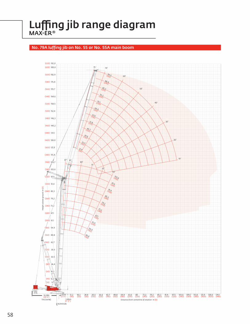
ROTATION
TAILSWING
1 8,00m(59' 0")
3,46m(11' 5" )
1,52 m(5' 0")
80⁰
70⁰
87 ⁰
75 ⁰
70⁰
50⁰
75 ⁰
60⁰
30⁰
40⁰
20⁰
85⁰10 ⁰
65⁰
97,5(320)
85,3(280)
103,6(340)
48,8(160)
54,9(180)
61,0(200)
91,4(300)
73,2(240)
67,1(220)
79,2(260)
51,8(170)
88,4(290)
57,9(190)
94,5(310)
64,0(210)
76,2(250)
45,7(150)
39,6(130)
33,5(110)
70,1(230)
82,3(270)
(90)27,4
(40) 12,2
(200) 61,1
(220) 67,1
(240) 73,2
(260) 79,2
(280) 85,3
(300) 91,4
(320) 97,5
(340) 103,6
(360) 109,7
(380) 115,8
(400) 121,9
(420) 128,0
(180) 54,9
(160) 48,8
(140) 42,7
(120) 36,6
(100) 30,5
(80) 24,4
(60) 18,3
(440) 134,1
(460) 140,2
(480) 146,3
(500) 152,4
(520) 158,5
(540) 164,6
(560) 170,7
(580) 176,8
(600) 182,9
(620) 189,0
(630) 192,0
(30) 9,1
48,8(160)
54,9 (180)
61,0 (200)
67,1 (220)
73,2(240)
42,7 (140)
36,6(120)
30,5 (100)
24,4 (80)
18,3(60)
12,2 (40)
79,2(260)
85,3(280)
91,4 (300)
97,5(320)
103,6(340)
109,7(360)
115,8 (380)
121,9(400)
128,0(420)
134,1(440)
Hei
ght
abov
e gr
ound
m (f
t)
Distance from centerline of rotation m (ft)
No. 79A luffing jib on No. 55 or No. 55A main boom
58
Luffing jib range diagramMAX-ER®

Meets ANSI B30.5 Requirements - Capacities do not exceed 75% of static tipping load.NOTICE: This capacity chart is for reference only and must not be used for lifting purposes.
48,8 (160)
334,6 (737.7)
327,0 (717.0)
315,9 (681.7)
282,5 (602.7)
248,0 (504.9)
196,5 (416.7)
61,0 (200)
– (632.0)
274,9 (584.0) 243,7 (530.6)
227,8 (478.5)
199,5 (433.3)
79,2 (260)
(( 87
189,0 (409.5) 175,2 (382.8)
166,8 (354.5)
150,4 (327.6)
128,8 (271.8)
91,4 (300)
– (313.5) 139,3 (305.7)
134,1 (286.8)
122,8 (268.1)
110,1 (241.6)
Boomm (ft)
Radius 16,8 ( 55)
18,0 (60)
20,0 (70)
24,0 (80)
26,0 (90)
30,0 (100)
36,0 (120)
42,0(140)
48,0(160)
54,0(180)
Luffi
ng ji
b le
ngth
27,
4 m
(90
ft)
Liftcrane luffing jib capacities - 18000 MAX-ER®
Luffing jib No. 79A on boom No. 55 or No. 55A with 42,7 m (140 ft) mast No. 56223 170 kg (492,000 lb) Counterweight 145 150 kg (320,000 lb) Carbody counterweight
390 090 kg (860,000 lb) Wheeled counterweight or hanging counterweight
360° Rating kg (lb) x 1 000
85˚Boomangle
48,8 (160)
223,8 (490.8)
215,1 (459.0)
195,0 (424.5)
160,2 (345.1)
128,3 (276.5)
103,7 (216.6)
61,0 (200)
– (390.4)
173,3 (371.2)
159,0 (346.6)
136,0 (295.2)
115,3 (249.8)
99,4 (215.7)
79,2 (260)
125,6 (271.0)
117,3 (256.5)
103,3 (224.9)
89,8 (195.1)
78,9 (171.5)
73,5 (163.4)
91,4 (300)
100,5 (218.0)
95,0 (207.8)
85,0 (185.2)
74,9 (162.9)
66,5 (144.6)
61,5 (135.7)
Boomm (ft)
Radius 16,8 ( 55)
18,0 (60)
20,0 (70)
24,0 (80)
26,0 (90)
30,0 (100)
36,0 (120)
42,0(140)
48,0(160)
54,0(180)
Luffi
ng ji
b le
ngth
45,
7 m
(15
0 ft
)
48,8 (160)
– (279.7)
117,8 (273.8)
112,0 (258.3) 101,0 (234.3)
77,9 (183.9)
59,2 (133.0)
61,0 (200)
103,3 (227.9)
98,3 (215.2) 89,6 (195.3)
71,0 (153.9)
55,8 (120.8)
79,2 (260)
–
77,2 (170.2)
73,7 (161.5) 67,8 (147.9)
54,7 (118.8)
43,8 (94.9)
38,4 (83.6)
91,4 (300)
59,8 (131.1) 55,2 (120.6)
45,1 (97.9)
36,4 (79.0)
32,0 (71.2)
Boomm (ft)
Radius 28,0 ( 95)
32,0 (105)
36,0 (120) 42,0 (140)
54,0 (180)
66,0 (220) 78,0 (260) 90,0 (300)
96,0 (320)
102,0 (340)
Luffi
ng ji
b le
ngth
70,
1 m (
230
ft)
48,8 (160)
68,4 (150.6)
53,8 (116.2)
38,8 (83.0)
26,2 (55.3)
– (33.3)
11,9 (24.2)
61,0 (200)
60,1 (131.8)
53,0 (115.5)
39,3 (84.3)
27,0 (57.2)
– (34.9)
12,6 (25.6)
79,2 (260)
––
45,2 (99.2)
39,9 (87.1)
33,7 (73.2)
25,5 (54.1)
– (34.3)
12,5 (25.6)
– (18.2)
Boomm (ft)
Radius 28,0 ( 95)
32,0 (105)
36,0 (120)
42,0 (140)
54,0 (180)
66,0 (220)
78,0 (260)
90,0 (300)
96,0 (320) 102,0 (340)
Luffi
ng ji
b le
ngth
94,
5 m
(31
0 ft
)
91,4 (300)
36,3 (79.6)
31,9 (69.6)
26,8 (58.2)
22,1 (45.5)
– (35.4)
13,1 (26.8)
– (19.2)
59Manitowoc 18000
Luffing jib load charts MAX-ER®

Meets ANSI B30.5 Requirements - Capacities do not exceed 75% of static tipping load.NOTICE: This capacity chart is for reference only and must not be used for lifting purposes.
48,8 (160)
– (700.0)
309,2 (650.5)
251,4 (539.5)
225,0 (458.4)
177,0 (363.5)
61,0 (200)
295,3 (631.2) 267,5 (581.5)
251,8 (512.9)
204,5 (438.3)
79,2 (260)
(( 87
191,5 (420.9)
177,4 (395.5)
169,2 (368.0)
148,2 (323.7)
91,4 (300)
– (319.1)
143,7 (314.1)
138,3 (301.0)
122,4 (266.6)
Boomm (ft)
Radius 22,0 (75)
24,0 (80)
26,0 (90)
30,0 (100)
32,0 (110)
36,0 (120)
42,0 (140)
48,0(160)
54,0(180)
60,0(200)
Luffi
ng ji
b le
ngth
27,
4 m
(90
ft)
Liftcrane luffing jib capacities - 18000 MAX-ER®
Luffing jib No. 79A on boom No. 55 or No. 55A with 42,7 m (140 ft) mast No. 56223 170 kg (492,000 lb) Counterweight 145 150 kg (320,000 lb) Carbody counterweight
390 090 kg (860,000 lb) Wheeled counterweight or hanging counterweight
360° Rating kg (lb) x 1 000
80˚Boomangle
48,8(160)
– (485.3)
215,5 (464.9)
192,2 (411.9)
149,5 (321.5)
121,0 (260.1)
97,7 (198.1)
61,0 (200)
189,5 (410.2)
178,9 (390.4)
157,4 (341.5)
130,1 (279.4)
106,9 (229.6)
79,2 (260)
130,9 (287.0)
119,5 (260.3)
105,9 (229.7)
92,9 (201.3)
83,6 (183.1)
91,4 (300)
97,6 (213.0)
88,1 (191.5)
78,4 (170.2)
70,6 (153.9)
Boomm (ft)
Radius 22,0 75)
24,0 (80)
26,0 (90)
30,0 (100)
32,0 (110)
36,0 (120)
42,0 (140)
48,0 (160)
54,0 (180)
60,0(200)
Luffi
ng ji
b le
ngth
45,
7 m
(15
0 ft
)
48,8 (160)
112,0 (248.1)
104,3 (222.2) 81,6 (175.2)
62,5 (137.5)
48,8 (95.5)
61,0 (200)
105,0 (232.0)
100,5 (216.2) 85,6 (185.5)
65,9 (145.1)
53,8 (115.1)
79,2 (260)
–
79,0 (174.7)
76,3 (164.7) 66,5 (144.4)
55,9 (123.2)
48,8 (105.7)
– (105.7)
91,4 (300)
61,9 (134.1) 54,7 (119.0)
46,6 (102.7)
41,0 (88.9)
37,7 –
Boomm (ft)
Radius 38,0 ( 130)
46,0 (150)
50,0 (170)
60,0 (200)
70,0 (230)
78,0 (260)
88,0 (290)
96,0 (320)
106,0 (350)
112,0 (370)
Luffi
ng ji
b le
ngth
70,
1 m (
230
ft)
48,8 (160)
64,8 (138.4)
51,9 (111.8)
39,5 (86.9)
30,7 (64.9)
– (46.4)
– (30.8)
61,0 (200)
– (128.4) 53,1 (114.7)
41,4 (91.1)
32,6 (69.3)
23,1 (50.3)
16,6 (34.2)
– (21.0)
79,2 (260)
––
45,8 (101.0)
39,3 (86.5)
32,0 (68.1)
23,4 (51.1)
17,4 (36.0)
– (23.1)
Boomm (ft)
Radius 38,0 ( 130)
46,0 (150)
50,0 (170)
60,0 (200)
70,0 (230)
78,0 (260)
88,0 290)
96,0 (320)
106,0 (350)
112,0 (370)
Luffi
ng ji
b le
ngth
94,
5 m
(31
0 ft
)
91,4 (300)
37,0 (81.2)
34,0 (74.9)
30,9 (67.2)
24,7 (53.8)
18,7 (38.9)
– (25.7)
8,7 –
60
Luffing jib load chartsMAX-ER®
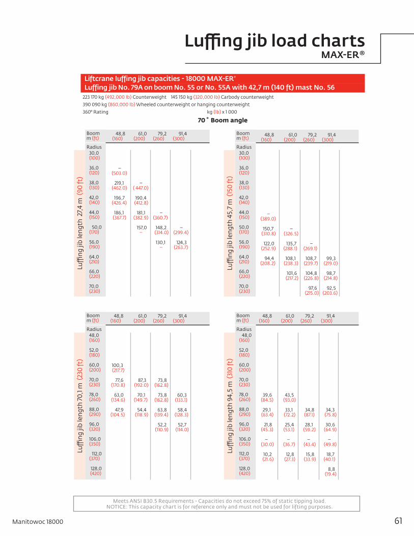
Meets ANSI B30.5 Requirements - Capacities do not exceed 75% of static tipping load.NOTICE: This capacity chart is for reference only and must not be used for lifting purposes.
48,8 (160)
100,3 (217.7) 77,6 (170.8)
63,0 (134.6)
47,9 (104.5)
61,0 (200)
87,3 (192.0)
70,1 (149.7)
54,4 (118.9)
79,2 (260)
–
73,8 (162.8)
73,8 (162.8)
63,8 (139.4)
52,2 (110.9)
91,4 (300)
60,3 (133.1)
58,4 (128.3)
52,7 (114.0)
Boomm (ft)
Radius 48,0 ( 160)
52,0 (180)
60,0 (200)
70,0 (230)
78,0 (260)
88,0 (290)
96,0 (320)
106,0 (350)
112,0 (370)
128,0 (420)
Luffi
ng ji
b le
ngth
70,
1 m (
230
ft)
48,8 (160)
– (503.0)
219,1 (462.0)
196,7 (426.4)
186,1 (367.7)
61,0 (200)
– ( 447.0)
190,4 (412.8)
181,1 (382.9)
157,0 –
79,2 (260)
(( 87
– (360.7)
148,2 (314.0)
130,1 –
91,4 (300)
– (299.4)
124,3 (263.7)
Boomm (ft)
Radius 30,0 ( 100)
36,0 (120)
38,0 (130)
42,0 (140)
44,0 (150)
50,0 (170)
56,0 (190)
64,0 (210) 66,0 (220)
70,0 (230)
Luffi
ng ji
b le
ngth
27,
4 m
(90
ft)
Liftcrane luffing jib capacities - 18000 MAX-ER®
Luffing jib No. 79A on boom No. 55 or No. 55A with 42,7 m (140 ft) mast No. 56223 170 kg (492,000 lb) Counterweight 145 150 kg (320,000 lb) Carbody counterweight
390 090 kg (860,000 lb) Wheeled counterweight or hanging counterweight
360° Rating kg (lb) x 1 000
70˚Boomangle
48,8 (160)
– (389.0)
150,7 (310.8)
122,0 (252.9)
94,4 (208.2)
61,0 (200)
– (326.5)
135,7 (288.1)
108,1 (238.3)
101,6 (217.2)
79,2 (260)
– (269.1)
108,7 (239.7)
104,8 (226.8)
97,6 (215.0)
91,4 (300)
99,3 (219.0)
98,7 (214.8)
92,5 (203.6)
Boomm (ft)
Radius 30,0 ( 100)
36,0 (120)
38,0 (130)
42,0 (140)
44,0 (150)
50,0 (170)
56,0 (190)
64,0 (210)
66,0 (220)
70,0 (230)
Luffi
ng ji
b le
ngth
45,
7 m
(15
0 ft
)
48,8 (160)
39,6 (84.5)
29,1 (63.4)
21,8 (45.3)
– (30.0)
10,2 (21.6)
61,0 (200)
43,5 (93.0)
33,1 (72.2)
25,4 (53.1)
– (36.7)
12,8 (27.3)
79,2 (260)
––
34,8 (87.1)
28,1 (59.2)
– (43.4)
15,8 (33.9)
Boomm (ft)
Radius 48,0 ( 160)
52,0 (180)
60,0 (200)
70,0 (230)
78,0 (260)
88,0 (290)
96,0 (320)
106,0 (350)
112,0 (370)
128,0 (420)
Luffi
ng ji
b le
ngth
94,
5 m
(31
0 ft
)
91,4 (300)
34,3 (75.8)
30,6 (64.9)
– (49.8)
18,7 (40.1)
8,8 (19.4)
61Manitowoc 18000
Luffing jib load charts MAX-ER®

Crane Care is Manitowoc’s comprehensive service and support program. It includes classroom and on-site training, prompt parts availability, expert field service, technical support and documentation.
That’s commitment you won’t find anywhere else.
That’s Crane Care.
Service training
Manitowoc specialists work with you in our training centers and in the field to make sure you know how to get maximum performance, reliability and life from your cranes.
Manitowoc Cranes Technical Training Centers provide valuable multi-level training, which is available for all models and attachments, in the following format:
• Intro to Canbus and Canbus 1, 2, 3• Intro to EPIC and EPIC 1, 2, 3• Small Crawler 1• Canbus 1 and 2 assembly, operation and
maintenance• EPIC 1 and 2 assembly, operation and
maintenance
Refer to www.manitowoc.com for course descriptions.
Parts availability
Genuine Manitowoc replacement parts are accessible through your distributor 24 hours a day, 7 days a week, 365 days a year.
Service interval kits 200 hour kit 1,000 hour kit 2,000 hour kit Hydraulic test kit U.S. standard tools kit
Field service
Factory-trained service experts are always ready to help maintain your crane’s peak performance.
For a worldwide listing of dealer locations, please consult our website at: www.manitowoc.com
Technical support
Manitowoc’s dealer network and factory personnel are available 24 hours a day, 7 days a week, 365 days a year to answer your technical questions and more, with the help of computerized programs that simplify crane selection, lift planning, and ground-bearing calculations.
For a worldwide listing of dealer locations, please consult our website at: www.manitowoc.com
Technical documentation
Manitowoc has the industry’s most extensive documentation; available in major languages and formats that include print, videotape, and DVD/CD.
Additional copies available through your Authorized Manitowoc Distributor.
• Crane operator’s manual • Crane parts manual • Crane capacity manual • Crane vendor manual • Crane service manual • Luffing jib operator’s/parts manual • Capacity chart manual - attachments
CD rom versions of the operator’s and parts manuals are shipped with each crane. Also available are the following CDs:
• Crane Care Owner CD – • Ground Bearing Pressure Estimator CD • Crane Selection and Planning Software (CompuCRANE©) • EPIC® Crane Library CD consisting of
capacity charts, range diagrams, wire rope specifications, travel specifications, crane weights, counterweight arrangements, luffing jib raising procedures, operating range diagrams, drum and lagging charts, boom rigging drawings, jib rigging drawings, outline dimensions and wind condition charts.
Available from your Authorized Manitowoc Cranes Distributor, these videos are available in NTSC, PAL, SECAM, and DVD formats.
• Your Capacity Chart Video • Respect the Limits Video • Crane Safety Video • Boom Inspection/Repair Video
Crane Care Package Manitowoc has assembled all of the available literature, CD’s and videos listed above plus several Manitowoc premiums into one complete Crane Care Package.
62
Manitowoc Crane Care

Manitowoc 18000 63
Notes

©2010 Manitowoc0510-18000 PG-US-E www.manitowoc.com
This document is non-contractual. Constant improvement and engineering progress make it necessary that we reserve the right to make specification, equipment, and price changes without notice. Illustrations shown may include optional equipment and accessories and may not include all standard equipment.
AmericasBrazilAlphavilleMexicoMonterreyChileSantiago
Europe,MiddleEast,AfricaCzech RepublicNetvoriceFranceBaudemontCergyDecinesGermanyLangenfeldHungaryBudapestItalyParabiagoNetherlandsBredaPolandWarsaw
PortugalBaltarRussiaMoscowU.A.E.DubaiU.K.Gawcott
Asia-PacificAustraliaBrisbaneMelbourneSydneyChinaBeijingChengduGuangzhouIndiaHyderabadPuneKoreaSeoulPhilippinesMakati CitySingapore
FactoriesBrazilAlphavilleChinaTaiAnZhangjiagangFranceCharlieuLa ClayetteMoulinsGermanyWilhelmshavenIndiaPuneItalyNiella TanaroPortugalBaltarFânzeresSlovakiaSarisUSAManitowoc Port WashingtonShady Grove
Regionaloffices
Manitowoc-AsiaPacificShanghai, China Tel: +86 21 6457 0066Fax: +86 21 6457 4955
Manitowoc-Europe,MiddleEast,AfricaEcully, France Tel: +33 (0)4 72 18 20 20 Fax: +33 (0)4 72 18 20 00
Manitowoc-AmericasManitowoc, Wisconsin, USA Tel: +1 920 684 6621 Fax: +1 920 683 6277
Shady Grove, Pennsylvania, USA Tel: +1 717 597 8121 Fax: +1 717 597 4062
Regionalheadquarters