1972 , volume , issue jan-1972 - about hp labs | hp® official … · · 2006-04-29tor give...
TRANSCRIPT

HEWLETT-PACKARD JOURNAL
J '
w*«
w á À
© Copr. 1949-1998 Hewlett-Packard Co.

A Computer-aided Hospital System for Cardiac Cat h éter iza t i on Procedures
Compu te r r educ t i on o f da ta acqu i red du r i ng ca rd iac ca the te r i za t i on e l im ina tes cons ide rab le penc i l and pape r compu ta t i on , a s ign i f i can t t ime-save r f o r t he phys i c ian . S imu l taneous l y , i t gua ran tees h igh l y soph i s t i ca ted measu remen ts wh i l e sho r ten ing a
no rma l l y l eng thy p rocedu re , a l ess d i squ ie t i ng expe r i ence f o r t he pa t i en t .
B y J o h n L . F a n t o n
MEDICAL DATA ACQUISITION SYSTEMS solve the problem of gathering meaningful information from a multitude of sources rapidly but, like their counterparts in industry, they very often create a new problem — how to digest all that data.
Cardiologists at the Stanford University School of Medicine are among those being buried under an avalanche of system-acquired data. With highly complex medical procedures such as cardiac valve replacement and organ transplants becoming wide spread, large amounts of data are being generated either during the operation itself or during the pa tient preparation phase or 'work up.'
One procedure contributing significantly to this glut of information is cardiac catheterization. A typical catheterization procedure may take up to four hours to complete, and it generates graphic records that require at least one and as much as three hours to reduce to useful form.
Making sure that the acquired cath lab data is meaningful presents an additional problem of some magnitude. While concerned with other duties, the cath lab technician may operate the strip-chart re corder incorrectly. Or, the data might be obscured by interference introduced by the catheter's posi tion. Additionally, there could be transient equip ment failure.
To assure that all the needed data is acquired and that this information is correct, measurements are often repeated. This introduces the most important problem of all — the comfort and safety of the pa tient. Thus, automatic data reduction is desirable not only for saving time in the data reduction phase, but, by directly presenting the physician with mea surement results while the catheters are in place, for reducing significantly the time the patient needs
to be in the cath lab. At the same time, this imme diate display of measurement results would permit more sophisticated investigations.
The Cardiology Division of the Stanford Univer sity School of Medicine therefore undertook the development of software for on-line analysis of data acquired during a catheterization procedure. Hewlett-Packard later joined them to develop a complete system for computerizing the data reduc tion. This effort has resulted in the HP Model 5690A Computerized Cardiac Catheterization Laboratory System.
C o v e r : K e y b o a r d a n d m o n i t o r g i v e n u r s e / t e c h n i c i a n s c o n t r o l o f c o m p u t e r i n n e w c o m p u t e r i z e d c a t h l a b m e a surement sys tem. Read i l y in t eg ra ted i n to ex i s t i ng p roce dures, system great ly speeds up i n t e rp re ta t i on o f da ta ac qu i r ed du r i ng ca rd i ac ca the
t e r i za t i on . Fo r an accoun t o f how th i s sys tem evolved, read the art ic le beginning on this page.
In this Issue: A Computer -A ided Hosp i ta l Sys tem
f o r C a r d i a c C a t h e t e r i z a t i o n P r o c e d u r e s , b y J o h n L . F a n t o n
Clip-and-Read Finds 1C Fai lures, by Mark Baker and Jesse Pipkin
The Wel l -Modulated Synthesizer, by James E. St inehel fer .
page 2
pages
page 13
P R I N T E D I N U . S . A .
© Copr. 1949-1998 Hewlett-Packard Co.

The Cath Lab
F a u l t y v a l v e s a n d o t h e r d e f e c t s i n t h e h e a r t ' s h y d r a u l i c operat ion — a i lments once considered i r remediable — can n o w b e c o r r e c t e d w i t h r e c e n t l y d e v e l o p e d o p e n - h e a r t s u r g i c a l t e c h n i q u e s . A n d w i t h t h e g r o w i n g p r a c t i c e o f o p e n - hear t su rgery has come an inc rease in ca rd iac ca the te r i za - t i o n p r o c e d u r e s , f o r t h i s i s w h e r e t h e r e a l n a t u r e o f t h e hear t ' s de fec ts a re de f ined .
Ca rd iac ca the te r i za t i on cons i s t s o f i nse r t i ng a t h i n , f l ex ib le , p las t ic tube ( the catheter ) in to a ve in or ar tery in e i ther an a rm or leg and s l id ing i t i n un t i l i t reaches the chambers o f t h e h e a r t . R e c o r d i n g s o f t h e d y n a m i c p r e s s u r e s i n t h e c h a m b e r s o f t h e h e a r t a n d n e a r b y a r t e r i e s m a y t h e n b e made s i nce p ressu re a t t he t i p o f t he ca the te r i s hyd rau l i - c a l l y c o u p l e d t o a n e x t e r n a l p r e s s u r e t r a n s d u c e r t h r o u g h a s a l i n e s o l u t i o n t h a t f i l l s t h e c a t h e t e r o r m e a s u r e d a t t h e t i p by t i ny so l i d - s ta te t r ansduce rs . The same ca the te r may a l s o b e u s e d f o r d r a w i n g o f f b l o o d s a m p l e s a t s e l e c t e d po in t s i n t he c i r cu la to r y sys tem. The pa t i en t ' s ECG i s a l so reco rded , p r ima r i l y t o p rov ide a t ime re fe rence f o r compar ing the phases o f p ressure wave fo rms recorded a t d i f fe ren t t imes.
F rom the in fo rmat ion ga thered dur ing the ca the te r i za t ion
p rocedure , the phys ic ian can de te rmine p ressure g rad ien ts across va lves, card iac output , vascu lar res is tance and other fac tors that ind icate prec ise ly the pos i t ion, s ize, and degree o f c a r d i a c a b n o r m a l i t i e s . V e r y o f t e n t w o o r p o s s i b l y t h r e e catheters, inser ted through separate b lood vessels, are used s o t h a t t w o o r m o r e p r e s s u r e s m a y b e r e c o r d e d s i m u l t a n e ous ly to prov ide measurements o f pressure d i f fe rent ia ls .
C a t h e t e r i z a t i o n i s p e r f o r m e d o n l y w h e n t h o r o u g h e x a m i na t ion by non- invas ive techn iques (X - rays , e lec t roca rd iog - raphy, hear t sound ana lys is , b lood chemis t ry ana lys is , e tc . ) i nd ica te tha t ca the te r i za t ion i s abso lu te ly necessary . I t i s a t r i c k y p r o c e d u r e a s t h e c a t h e t e r t i p m a y n o t a l w a y s f o l l o w the in tended path , ca l l ing for cons iderab le back ing o f f , tw is t ing , and p rob ing , espec ia l l y when gu id ing the ca the te r pas t o n e o r m o r e o f t h e h e a r t ' s v a l v e s . T h e p h y s i c i a n m o n i t o r s t h e p r o g r e s s o f t h e c a t h e t e r w i t h a f l u o r o s c o p e . H e a l s o w a t c h e s t h e p r e s s u r e w a v e f o r m s o n a l a r g e - s c r e e n m o n i t o r because the na tu re o f t he wave fo rms ass i s t h im in mak i ng j udgmen ts abou t ca the te r t i p pos i t i on ing .
The ca th lab p rocedure may take two o r more hours . The pat ient rece ives on ly a loca l moderate anesthet ic s ince mea s u r e m e n t s a r e m a d e b o t h i n t h e r e s t i n g s t a t e a n d d u r i n g exerc i se (ca th lab equ ipment i nc ludes a b i cyc le -peda l exe r c iser tha t can be used wh i le the pa t ien t i s l y ing down) .
The end resu l t o f a ca th lab p rocedure i s 20 fee t o r more o f osc i l l og raph i c r eco rd ings o f p ressu re wave fo rms , and a l i s t i n g o f c h e m i c a l a n a l y s e s p e r f o r m e d o n t h e b l o o d a n d r e s p i r e d a i r . T h e p h y s i c i a n m u s t t h e n s p e n d t w o o r m o r e hours ana lyz ing the da ta . He reduces the da ta by f i r s t mea su r ing the peaks , va l l eys , and g rad ien ts o f t he wave fo rms . These numbers a re then used fo r t he ca l cu la t i ons requ i red to ge t the des i red in fo rmat ion .
W i th t he compu te r sys tem desc r i bed he re , t hese ca l cu la t i o n s a r e p e r f o r m e d o n - l i n e d u r i n g t h e c a t h e t e r i z a t i o n p r o cedure . Th is shor tens the t ime the pa t ien t needs to be kep t i n t h e c a t h l a b , s i n c e i m m e d i a t e a v a i l a b i l i t y o f t h e c a l c u l a ted da ta can gu ide the cou rse o f t he ca th l ab p rocedu re , a l l t he wh i l e assu r i ng t ha t t he necessa ry da ta i s acqu i red . I t a l s o r e d u c e s t h e p h y s i c i a n ' s w o r k l o a d b y a s i g n i f i c a n t fac to r , leav ing h im more t ime fo r d i rec t pa t ien t care .
Meet ing Medical Needs Objectives mutually agreed upon at the begin
ning of the system development included: • Computer results must be presented in a form
useful to the physician. • No constraints should be placed on the accepted
cath lab procedure because of the computer. • The system should not require additions to the
cath lab team. • Computer failure must not compromise the pro
cedure. • The cost of the system should be commensurate
with the time saved. Fortunately, the Stanford Cardiology Division
was able to provide a clinical environment for sys tem evaluation. HP engineers, after a literature study of cardiac physiology and disease, spent a number of weeks in an operating cath lab observ
ing what the system operating environment is, what each member of the team does, and what the in dividual stress levels are. Considerable time was spent with each member of the catheterization team to determine how a computerized system could improve the existing manually-handled pro cedures. From this, a computerized cardiac cathe terization system evolved, a system that is easily used by medical personnel who do not have a com puter background.
T h e S y s t e m The computerized cath lab system is actually
comprised of two systems: an analog measurement system and the computer system (Fig. I}.
The analog measurement system includes the pressure transducers and ECG electrodes, suitable medically-oriented preamplifiers, a large-screen dis-
© Copr. 1949-1998 Hewlett-Packard Co.

play for the waveforms, and an optical strip-chart recorder. It feeds the analog waveforms to an ana log-to-digital converter for use by the computer.
Although the preamplifiers were modified to al low automatic calibration in response to computer commands, the analog system can still be used by itself to make cath-lab measurements in the tradi tional non-computerized manner. This allows the smaller hospital to equip a cath lab with the ana log system alone, and then to add the computer system when increased cath lab usage warrants.
The computer system can be either of the HP Disc Operating Systems: the DOS fixed-head disc system, or the DOS-M Moving-Head Disc System (a little slower but less expensive). Neither of these software executives were modified, allowing the computer to be used for other tasks when the cath lab is not in use.
The Gist of the Problem Hardware development centered on the man-
machine interface, in many ways the most difficult part of the development to define. Stanford per sonnel had previously determined that the tradi tional teletype interface is unsuitable for the cath lab because the noise could be disturbing and its operation would be too time-consuming for those who do not have a computer background. What was desired was a calculator-like keyboard that could process data according to directions imparted by the simple push of a button.
As a result of this need, a special-purpose key board was designed. The first prototype is shown in Fig. 2(a). It has special computation keys along the bottom and a typewriter-style keyboard that lets the nurse/technician enter notes during a pro cedure, obviating the need for making entries in the protocol log book.
A few weeks' experience in the cath lab dis closed that the typewriter keyboard was imprac tical. Few technicians are accomplished typists and the necessity for darkening the room during X-ray procedures prohibited 'hunt and peck' typing. The same trial period also disclosed problems with the grouping of the computation keys. Nurses often had trouble finding certain keys at critical moments.
So, back to the drawing board. A second key board evolved. As shown in Fig. 2(b], the type writer keyboard is eliminated and the computation keys are grouped into blocks according to function. Frequently used keys are on the corners of the blocks where they can be found easily by touch. This keyboard came much closer to fulfilling the goal of usefulness without special training.
From discussions with the staff using this key board, further refinements were made. The result ing third prototype, Fig. 2(c), became the final design when trials for this keyboard showed that it fulfilled all objectives and required only a brief familiarization period.
Interaction Cathode-ray tube display of data and intermedi
ate program steps closes the operator loop to give full interactive operation with the computer. CRT display was chosen because of its speed, versatility, and absolute silence.
To avoid adding equipment to the laboratory, it was decided to display the data on the same TV monitor used for the X-ray image intensifier. The monitor is installed where the physician can view it without moving from the catheterization table and, because it displays an image only when the X-ray system is turned on, it is available for data display during the measurement periods.
Subsequent observations indicated that the mon itor was not in a position where the recording technician could watch the monitor while selecting keys, so a small monitor was added at the keyboard.
The system still includes a teletype, but this is installed in the computer room where it is used for entering off-line data such as patient identification number, name, weight, etc. It also prints a hard- copy report at the conclusion of the cath lab pro cedure.
Opt ica l R e c o r d e r ^ H T a p e
R e c o r d e r Osci l loscope
F ig . 1 . Typ i ca l con f i gu ra t i on o t ca th l ab sys tem.
© Copr. 1949-1998 Hewlett-Packard Co.

(a)
(b)
(c)
F i g . 2 . K e y b o a r d s t r a c e s y s t e m d e v e l o p m e n t . F i r s t p r o t o t y p e ( a ) h a d c a l c u l a t o r - l i k e f u n c t i o n k e y s p l u s a l p h a n u m e r i c k e y b o a r d . A l p h a n u m e r i c s e c t i o n , l o u n d t o b e s u p e r f l u o u s , w a s d e l e t e d f r o m s e c o n d p r o t o t y p e ( b ) . F u r t h e r r e f i n e m e n t s i n k e y a r r a n g e m e n t w e r e m a d e i n f i n a l p r o t o t y p e ( c ) . B l a n k p u s h b u t t o n s a r e f o r f u n c t i o n s t h a t m a y b e a d d e d a s m o r e e l a b o r a t e p r o c e d u r e s a r e developed.
Stra ight forward Commands Software, based on the Stanford-developed For
tran programs, was designed with the nurse/tech nician staff in mind. Wherever possible, control codes were based upon accepted abbreviations for medical terms. For example, LA and RA indicate left atrium and right atrium respectively. Actually, the software includes some twenty independent programs that can be called up in any order accord
ing to the keyboard commands. This allows the physician wide latitude in selecting the order in which measurements are to be made.
Substantial time was spent making sure that no combination of keyboard commands could abort the system. One worthwhile feature that was added is a RESET command. It had been noticed that under a high-stress condition the operator could become confused part way through a sequence of commands and become completely lost. The RESET command returns the program to an easily recog nized point, allowing the operator to start again.
Uninterrupted Data Flow To insure no loss of data, system backup re
ceived considerable attention. The analog system provides a first-level back-up for possible com puter failure because it can continue to generate records for manual reduction.
A second back-up is provided, however, in the form of a mag tape recorder. This not only records the analog signals, but it also records coded signals in response to the keyboard commands. When the computer is up again, the tape can be replayed into the computer. The computer then reduces the data immediately under control of the recorded com mands. (The tape system also records comments by the technician on a voice track.)
Economical in i ts Way Improved patient care could justify this system
without economic considerations, but hospitals do not have unlimited funds and must consider eco nomics when allotting resources. The economics of this system can be interpreted in terms of time saved for the physician. If his time is valued in a range of $20 to $40 per hour, a cath lab doing two procedures a day can save about $30,000 a year, a significant amount in light of the cost of a typi cal system ($67,000). A new version of the system using the HP Real-Time Executive will allow up to four cath labs to share one computer, reducing unit costs even further.
Field Proven The prototype system at Stanford has been oper
ating for over a year and has been used on more than 250 patients. Comparisons of computer-de rived results with those of cardiologists working in the traditional manner show excellent agreement, establishing this system as a worthwhile addition to the tools required by a sophisticated cardiology department.
© Copr. 1949-1998 Hewlett-Packard Co.

Finding a Good Waveform
P r e s s u r e w a v e f o r m s r e t a i n e d i n c o m p u t e r a r e r e - c r e a t e d t o r d i s p l a y w i t h i n s e c o n d s o t a n a l o g w a v e f o r m s a m p l i n g . M a r k e r s s h o w p o i n t s s e l e c t e d f o r c a l c u l a t i o n s ( e . g . p e a k s y s t o l i c p r e s s u r e , b e g i n n i n g d i a s t o l i c p r e s s u r e , e n d d i a - s to l i c p ressu re , dp /d t , e t c . ) .
Ana log record ing o t ECG and typ ica l p ressure wave fo rm.
The a lgo r i thms fo r reduc ing raw phys io log ica l wave fo rms t o m e a n i n g f u l i n f o r m a t i o n w e r e d e v e l o p e d m o s t l y b y m e m be rs o f t he S tan fo rd Un i ve rs i t y Schoo l o f Med i c i ne ' s Ca rd i o l o g y D i v i s i o n . T h e p r o b l e m s i n h e r e n t w i t h p h y s i o l o g i c a l s igna ls , main ly low s igna l - to-no ise ra t ios and var iab le s igna l qua l i t y , requ i red ra ther compl ica ted dec is ion c r i te r ia to iden t i f y po in ts o f in te res t .
In response to an opera tor command, the sys tem's A- to-D c o n v e r t e r s a m p l e s a w a v e f o r m a t a 1 0 0 - H z r a t e . S a m p l i n g cont inues unt i l the system has counted 1 1 heartbeats der ived f r o m t h e E C G . B e c a u s e o f u n c e r t a i n t i e s i n t h e b e g i n n i n g a n d e n d o f a p r e s s u r e w a v e f o r m , d a t a f r o m t h e f i r s t a n d las t beats are d iscarded, insur ing tha t a l l 9 o f the remain ing bea ts a re comp le te ca rd iac cyc les .
The samples are passed through a d ig i ta l f i l te r ' to remove no ise . The f i l te r numer ica l l y convo lves each sample w i th an 11 -po in t we igh ted average . The f i l te red da ta i s then s to red on t he d i sc memory f o r l a te r ana l ys i s .
When ana l ys i s i s r eques ted , t he sys tem f i r s t checks t he ana tomica l s i te be ing measured and then se lec ts the appro p r i a t e a l g o r i t h m . T h e a n a l y s i s i s b e y o n d t h e s c o p e o f t h i s a r t i c le bu t i t i nvo lves dec is ion c r i te r ia based on t ime, amp l i tude, and rate of change.4 '5 Af ter analys is , the reconstructed waveforms are d isp layed w i th marks to ind ica te where wave f o r m v a l u e s a r e t o b e c h o s e n , e . g . p e a k s y s t o l i c a n d d i a s to l ic pressures.
To fur ther reduce anomal ies , the chosen va lues o f a l l n ine c a r d i a c - c y c l e s a r e r a n k o r d e r e d . T h e m i d d l e - t h r e e v a l u e s a r e t h e n a v e r a g e d t o o b t a i n t h e r e p o r t e d v a l u e , t h e u p p e r t h r e e a n d l o w e r t h r e e b e i n g i g n o r e d . T h i s r e m o v e s a b n o r ma l bea ts , such as those caused by p re -ven t r i cu la r con t rac t ions wh ich resu l t in one beat w i th abnormal ly h igh pressure a n d o n e w i t h a b n o r m a l l y l o w p r e s s u r e . T h e v a l u e r e p o r t e d i s t hus t ru l y rep resen ta t i ve . The sys tem then compu tes va l ues fo r va lve g rad ien ts , va lve a reas , ca rd iac ou tpu t , s t roke vo lume, sys to l i c e jec t ion per iod , d ias to l i c f i l l i ng per iod , and any o ther ca l led paramete rs .
Keyboard Cont ro l
Ca l ibra t ion
P ick Card iac Output 0 S a t u r a t i o n s , H g b 0 C o n s u m p t i o n
Recorder
ECG Pressures And Dye Di lu t ion Curve
F ig . 3 . I n fo rma t i on f l ow . F ig . 4 . Mon i to r d isp lays ca lcu la t ions ca l led fo r dur ing
catheter izat ion procedure.
© Copr. 1949-1998 Hewlett-Packard Co.

F ig . 5 . Compu te r p r i n t s ou t three-page repor t a t conc lus ion
of catheter izat ion data.
Acknowledgments The author wishes to express great appreciation
to the Division of Cardiology of Stanford Univer sity for their guidance, particularly to Dr. Donald Harrison and Mr. William Sanders without whose help the Computerized Cardiac Catheterization Lab oratory System would not be a reality. Thanks are also extended to Richard Regan for his work on the keyboard and control section, f
Bibliography 1. Ridges, J. D., Sanders, W. J., and Harrison, D. C., 'Computer Analysis of Arterial Pressures,' Procedures, 23rd Annual Conference on Engineering in Medicine and Biology, Vol. 12, No. 11, 1970. 2. Stenson, R., Grouse, L., and Harrison, D. C., 'Cardiac Output Determinations, Comparison of Computer, Pick, and Dow Methods.' Submitted for publication Novem ber, 1970. 3. Savitsky, S., Golay, M. J., 'Smoothing and Differen tiation of Data by Simplified Least Squares Procedure,' Analytical Chemistry, 36:1627, 1964. 4. Henry, W. L., Grouse, L., Stenson, R., Harrison, D. C., 'Computer Analysis of Cardiac Catheterization Data,' American Journal of Cardiology, Vol. 22, Nov. 1968. 5. Harrison, D. C., Miller, H., 'Calculating Cardiac Cath
eterization Data with an On-Line Computer System,' Hewlett-Packard Co., Medical Electronics Division, Waltham, Mass.
John L. Fanton
With BSEE and MSEE degrees f rom Corne l l i n hand , John Fanton jo ined Hewle t t -Packard 's Med ica l E lec t ron ics Div is ion in 1968. In i t ia l ly he worked on the design of a s ing le-channel ECG recorder for nurses ' s ta t ions and then went on to the wor ld of mul t ichannel systems and computers as pro jec t leader fo r the Computer ized Cath Lab System. John is marr ied and, wi th but one chi ld so far , he st i l l has t ime for sk i ing, photography, and music.
© Copr. 1949-1998 Hewlett-Packard Co.

Clip-and-Read Comparator Finds 1C Failures
Here's equipment. clever new tool for troubleshooting digital integrated-circuit equipment.
By Mark Baker and Jesse Pipkin
You probably wouldn't use a sledgehammer to crack a walnut. Or a scrub brush to clean your teeth. Or (usually] an oscilloscope to measure volt age. In these and countless other tasks, doing an efficient job is largely a matter of choosing the right tool. Until recently, however, when it came to troubleshooting digital integrated circuits in design, production, or service, the right tool just didn't exist. There was no alternative to tedious and expensive methods involving manuals, sche
matics, specifications, oscilloscopes and voltmeters — methods that could only be applied by someone with a high level of technical skill.
The situation is different now. Model 10529A Logic Comparator, Fig. 1, may well be the right tool for finding a digital 1C failure. It's a simple, inexpensive, hand-held device that quickly identi fies a faulty 1C and tells which pins have failed.
Fig. 2 shows how the comparator is used. For an unskilled person the method is fast and nearly
F i g . 1 . M o d e l 1 0 5 2 9 A L o g i c C o m p a r a t o r t i n d s f a u l t y T T L o r D T L i n t e g r a t e d c i r c u i t s q u i c k l y and eas i l y . I t ' s se l f -powered , ad jus tment t ree , and requ i res l i t t l e training.
© Copr. 1949-1998 Hewlett-Packard Co.

F i g . 2 . H e r e ' s h o w t o u s e t h e l og i c compara to r , (a ) Se lec t t he 1C to be tested and read i ts num ber , (b) Select a re ference board c o n t a i n i n g a g o o d 1 C w i t h t h e same number , ( c ) I nse r t t he r e f e r e n c e b o a r d i n t h e c o m p a r a t o r ' s d rawe r , ( d ) A t t ach t he c l i p t o t he 1C to be tes ted , (e ) Look a t t h e d i s p l a y . T h e ' O N ' l i g h t c o m e s o n i t t h e c l i p i s p r o p e r l y a t t a c h e d . A n y o t h e r l i g h t i n d i c a t e s a n o u t p u t p i n o à t h e 1 C b e i n g t e s t e d w h i c h d o e s n ' t a c t l i k e t h e s a m e p i n o l t h e r e f e r ence 1C.
foolproof. For someone with experience or training it may be still faster, since such a person will be able to deduce the likely problem area before test ing. In many cases the comparator finds failed IC's an order of magnitude faster than other methods.
How I t Works Comparator operation is as follows: select the
1C to test, put a similar 1C in the comparator's drawer, attach the clip to the 1C, and watch the results. The comparator displays any logic-state difference between the test 1C and the reference 1C.
When the comparator is clipped onto a test 1C, the inputs of the reference 1C are tied in parallel with those of the test 1C. The outputs are allowed to respond separately. The necessary connections are made on the small board that contains the ref erence 1C (Fig. 2b]. On this board, traces are broken to identify output pins of the test and reference IC's. V,c and ground connections are also made on this board to supply power to the comparator. This is done by bending and soldering the V, c and ground pins of the reference 1C to the V, c and ground buses (Fig. 3). Thus the comparator draws its power from
the power supply of the circuit under test. Sixteen light-emitting diodes (LED's) are used in
the comparator as fault indicators. Each LED cor responds to a pin on a fourteen- or sixteen-pin dual- in-line package. A lighted diode indicates an error at the corresponding pin. Even a very short error (200 nanoseconds or greater) is stretched enough to be easily detectable.
An indication that the clip is placed on the test 1C in the proper orientation is given by a seven teenth LED. The comparator is protected against damage that might occur if the clip were placed on the test 1C improperly.
Circuit loading is minimized by the use of low- power circuitry within the comparator. Outputs of the 1C under test see only one low-power load. Outputs of other IC's that drive inputs of the test 1C are loaded by a maximum of 1.2 additional stan dard TTL loads.
In-House Applications Abound How useful is the logic comparator? Hewlett-
Packard's own experience is revealing. A number of production lines have found the
© Copr. 1949-1998 Hewlett-Packard Co.

F i g . 3 . O u t p u t p i n s a r e i d e n t i f i e d b y d r i l l i n g h o l e s i n t h e r e f e r e n c e b o a r d . V c c a n d g r o u n d c o n n e c t i o n s a r e a l s o made on t h i s boa rd t o supp l y power t o t he compara to r .
comparator invaluable for isolating failures in shift registers, decades, and other logic IC's. It is used as the primary troubleshooting aid for the 5505A Laser Interferometer Display Unit. The 5360A Com puting Counter production line has found it to be nearly indispensable. In the IC-counter areas, the comparator isolates problems ten times faster than conventional techniques. Users may disagree on just how much time the comparator saves but all agree that even the least skilled personnel can iso late 1C failures knowing very little about the cir cuitry. Of course, being able to specify the general area of failure — knowledge gained from experience — speeds up the process, but anyone who can read the identification numbers on the IC's can quickly check every TTL and DTL 1C in a circuit.
The logic comparator also locates solder bridges and other improper connections. If an output is held high or low by a shorted lead, it will appear as a failure; thus a failure indication on the comparator locates these stray misconnections.
Two situations require special treatment. When wire-AND connections are used, an output is con strained to be different from what one might expect from observing the inputs of the test 1C. The com parator will locate this discrepancy and the user can then refer to the circuit schematic to determine that no failure exists. Shorts inside an 1C input, always difficult to isolate, are detected by the com parator as a failure in the driving 1C.
The Hewlett-Packard service organization is now incorporating troubleshooting with the logic com parator into HP service manuals. Extensive pro
grams involving the 5360A Computing Counter and the 5401B Multichannel Analyzer are now under way to evaluate the comparator's impact on the entire concept of field servicing. Several service managers see an eventual end to the expensive and cumbersome spare-board concept and envision in stead a portable 1C in-circuit tester as the major component of the field service kit. After locating the general area of failure, the repair technician would test the suspect IC's in much the same way that television tubes are tested, except that it isn't necessary to remove the IC's from the circuit.
In the laboratories, HP engineers are also using the comparator. A major benefit is its ability to spot errors that occur at such low repetition rates that they would be difficult to see with an oscillo scope. In some cases, methods of using the logic comparator are being included in new-instrument test specifications released to production.
What Makes I t T ick The logic comparator consists of sixteen identical
circuits and a reverse-polarity protection circuit. Each of the sixteen circuits consists of an exclusive- OR circuit followed by a pulse stretcher and an LED driver (Fig. 4). All integrated circuits are of the low- power variety except the NOR circuit which serves as the LED driver.
An output of the reference 1C is connected to one input of the exclusive-OR circuit and the corre sponding output of the circuit under test is con nected to the other input. Any time there is a difference between the inputs of the exclusive-OR circuit, point A goes to a logical '!' state. This forces the output of the NOR gate (point C) to a logical '0' state and turns on the LED through the current- limiting resistor. Each time point A goes to a '!' state, point B also goes to a T state for 100 ms.
F ig . 4 . S i x teen o f t hese compara to r c i r cu i t s compare t he test and reference IC's pin by pin.
10
© Copr. 1949-1998 Hewlett-Packard Co.

Probe, Clip, Comparator — Three Complementary 1C Logic Testers
The new 10529A Log ic Compara tor i s the th i rd in a ser ies o f l o w - c o s t , e a s y - t o - u s e t o o l s d e s i g n e d s p e c i f i c a l l y f o r t e s t i n g T T L a n d D T L d i g i t a l i n t e g r a t e d c i r c u i t s . M o d e l 10525A Log i c P robe1 checks t he dynam ic behav io r a t i nd i v idua l p ins . A l igh t a t the p robe 's t ip ind ica tes a h igh o r low log ic s ta te and a pu lse s t re tcher ca tches pu lses as shor t as 25 nanoseconds and g i ves a 0 .1 - second v i sua l i nd i ca t i on . M o d e l 1 0 5 2 8 A L o g i c C l i p 1 i s a s e l f - p o w e r e d d e v i c e t h a t c l ips on to four teen- o r s i x teen-p in dua l in - l i ne 1C packages a n d d i s p l a y s t h e s t a t e s o f a l l p i n s o n t w o r o w s o f l i g h t - e m i t t i n g d i o d e s . P r o b e , c l i p , a n d c o m p a r a t o r c o m p l e m e n t one another and enhance one another 's va lue. Model 501 OA L o g i c T r o u b l e s h o o t i n g K i t c o n t a i n s a l l t h r e e . T h e y ' r e a l s o avai lable separate ly .
References 1 . G . B . G o r d o n , ' 1 C L o g i c C h e c k o u t S i m p l i f i e d , ' H e w l e t t - Packard Journa l , June 1969 . 2 . 'De f t l y Des igned †” The Log ic C l i p , ' EDN, Mar 1 , 1970 .
M o d e l 5 0 1 0 A 1 C t r o u b l e s h o o t i n g k i t c o n t a i n s a 1 0 5 2 5 A L o g i c P r o b e , a 1 0 5 2 8 A L o g i c C l i p , a n d a 1 0 5 2 9 A L o g i c Comparator .
This 100 ms is the time required to charge the 3.3 /iF capacitor to 1.4 V (TTL threshold) through the 68 kfi resistor and the inverter input impedance. Fast recovery time in the stretcher loop is obtained by means of the Zener diode which limits the maximum voltage between the inverter input and ground to 3.16 V. The 400 pF capacitor on the output of the exclusive-OR circuit is used to slow down its response to make it immune to short
error indications caused by different propagation delays in the reference 1C and the circuit under test.
Self-Test Since the comparator is a troubleshooter for other
instruments, it's especially important that the user have confidence in it. For this reason a self-check board is included with each comparator (Fig. 5). The test board is plugged into the reference slot of the comparator and is powered by 5 V from any laboratory power supply.
The self-check board has two test modes. The first mode exercises all the comparator's electronics and the LED indicators. The test is completed by observing that all LED indicators blink in unison at approximately 1 Hz when the test board is in serted and +5 V is applied. This test exercises the comparator with various input combinations includ ing the case of a very short fault which requires the pulse-stretching capability.
The second test mode checks for continuity from the clip through the cable to the comparator. This test is made by connecting the clip to a dummy 1C on the test board and observing the LED's blinking in unison at approximately 2 Hz. If one wire in the cable is discontinuous, the LED corresponding to that pin position blinks at one-half the rate of the LED's surrounding it.
The test board delivers two waveforms to the logic comparator. One waveform represents signals coming from the reference 1C and the other repre sents the waveform coming from the circuit under test. The combination of these waveforms gives a complete check of the comparator. In the cable-test check mode, the clip is placed on an 1C with all pins connected to ground. This grounding of the clip eliminates (grounds] one of the waveforms and
F i g . 5 . S e l f - c h e c k b o a r d i s i n s e r t e d i n t h e c o m p a r a t o r ' s d r a w e r t o m a k e s u r e t h e c o m p a r a t o r i s t u n c t i o n i n g proper ly .
11
© Copr. 1949-1998 Hewlett-Packard Co.

hence changes the display. Any broken wire would therefore show up as having a blinking pattern un changed by the grounding of the clip.
The test board produces the waveforms by gating signals from a counter and one of its differenti ated outputs. The differentiator supplies the pulses necessary to test the pulse stretchers. The counter is clocked by a unijunction-transistor relaxation oscillator.
Mechanica l Des ign The logic comparator is designed for heavy use.
An aluminum extrusion serves as a one-piece case, board support, and reference-drawer guide. Easy insertion of the reference card is accomplished by a plastic molded drawer mechanism which accepts the reference board and guides it into its connector.
Acknowledgments The industrial design of the logic comparator is
by David Goelz and James Hergert. Initial feasi bility was proved by Gary Gordon and Jon Garman. Roy Criswell smoothed the road to production. S
Mark Baker Mark Baker's a project manager ¡n the logic test section at HP's Santa Clara Div is ion. He received his B.S. degree in e lect r ica l engineer ing f rom Oklahoma State Univers i ty ¡n 1969 and his M.S.E.E. from Stanford University in 1970. At HP, s tar t ing in the summer of 1969, he 's designed the 10528A Logic Cl ip and cont r ibuted to the des ign of the 5525A Laser In ter ferometer System and the 10529A Logic Comparator . Obvious ly ( log ica l ly?) an outdoor enthus iast , Mark puts water sk i ing, tennis, and hunt ing at the top of h is l is t of preferred act iv i t ies.
S P E C I F I C A T I O N S H P M o d e l 1 0 5 2 9 A Logic Comparator
I N P U T T H R E S H O L D : 1 . 4 V n o m i n a l , T T L o r D T L c o m p a t i b l e .
T E S T 1 C L O A D I N G : 1 C d r i v i n g t e s t 1 C i n p u t s l o a d e d b y 2 l o w - p o w e r T T L l o a d s p l u s i n p u t o f R e f e r e n c e 1 C . T e s t 1 C o u t p u t s l o a d e d b y 2 l o w - p o w e r T T L l o a d s .
I N P U T P R O T E C T I O N : V o l t a g e s < - 1 V o r > 7 V m u s t b e c u r r e n t l i m i t e d t o 1 0 m A .
S U P P L Y V O L T A G E : 5 V Â ± 1 0 % .
S U P P L Y P R O T E C T I O N : S u p p l y v o l t a g e m u s t b e l i m i t e d t o 7 V .
M A X I M U M C U R R E N T C O N S U M P T I O N : 3 0 0 m A .
S E N S I T I V I T Y : E R R O R S E N S I T I V I T Y :
2 0 0 n s . E r r o r s g r e a t e r t h a n t h i s a r e d e t e c t e d a n d s t r e t c h e d t o a t l e a s t 0 . 1 s e c o n d .
D E L A Y V A R I A T I O N I M M U N I T Y : 5 0 n s . E r r o r s s h o r t e r t h a n t h i s v a l u e a r e c o n s i d e r e d s p u r i o u s a n d i g n o r e d .
T E M P E R A T U R E : 0° to 55°C.
D I M E N S I O N S : 1 . 4 i n d e e p , 3 . 3 7 5 i n w i d e , 7 . 1 5 i n l o n g ( 3 , 5 6 x 8 , 5 5 x 1 8 , 2 c m ) .
W E I G H T : N e t , 2 I b 6 o z ( 1 , 1 4 k g ) . S h i p p i n g , 3 I b 6 o z ( 1 , 6 2 k g ) .
A C C E S S O R I E S I N C L U D E D : 1 t e s t b o a r d ; 1 0 b l a n k r e f e r e n c e b o a r d s ; 1 c a r r y i n g c a s e .
A C C E S S O R I E S A V A I L A B L E : M o d e l 1 0 5 4 1 A s u p p l y o f r e f e r e n c e b o a r d s i n c l u d e s 2 0 b l a n k r e f e r e n c e b o a r d s a n d s t o r a g e c o n t a i n e r . P r i c e : $ 5 0 . 0 0 .
P R I C E : M o d e l 1 0 5 2 9 A : 1 t o 4 u n i t s , $ 2 9 5 . 0 0 . 5 t o 9 u n i t s , 5 2 9 0 . 0 0 . 1 0 t o 1 9 u n i t s , $ 2 8 5 . 0 0 . F o r l a r g e r q u a n t i t i e s , p l e a s e c o n s u l t H e w l e t t - P a c k a r d .
M A N U F A C T U R I N G D I V I S I O N : S A N T A C L A R A D I V I S I O N 5 3 0 1 S t e v e n s C r e e k B o u l e v a r d S a n t a C l a r a , C a l i f o r n i a 9 5 0 5 0
Jesse Pipkin Five years as a U.S. Air Force navigator taught Jesse Pipk in how to get where he wants to go. So far , that 's been to the Universi ty of Flor ida, where he got h is B.S.E.E. degree in 1 967 and then to HP as an appl icat ions engineer spec ia l iz ing in the 8540A Network Ana lyzer . Co inc identa l^ , among the dut ies o f that job was to be nav igator /p i lo t for a mobi le network analyzer demonstrat ion uni t . Jesse f ina l ly landed at HP's Santa Clara Div is ion, where he 's now product manager for log ic test dev ices. He 's a member of IEEE and an avid skier.
12
© Copr. 1949-1998 Hewlett-Packard Co.
The Well-Modulated Synthesizer Whi le preserv ing synthes izer qua l i t ies , means are found to
modu la te ou tpu t w ide ly , p rec ise ly , and remote ly .
By James E. Stinehelfer
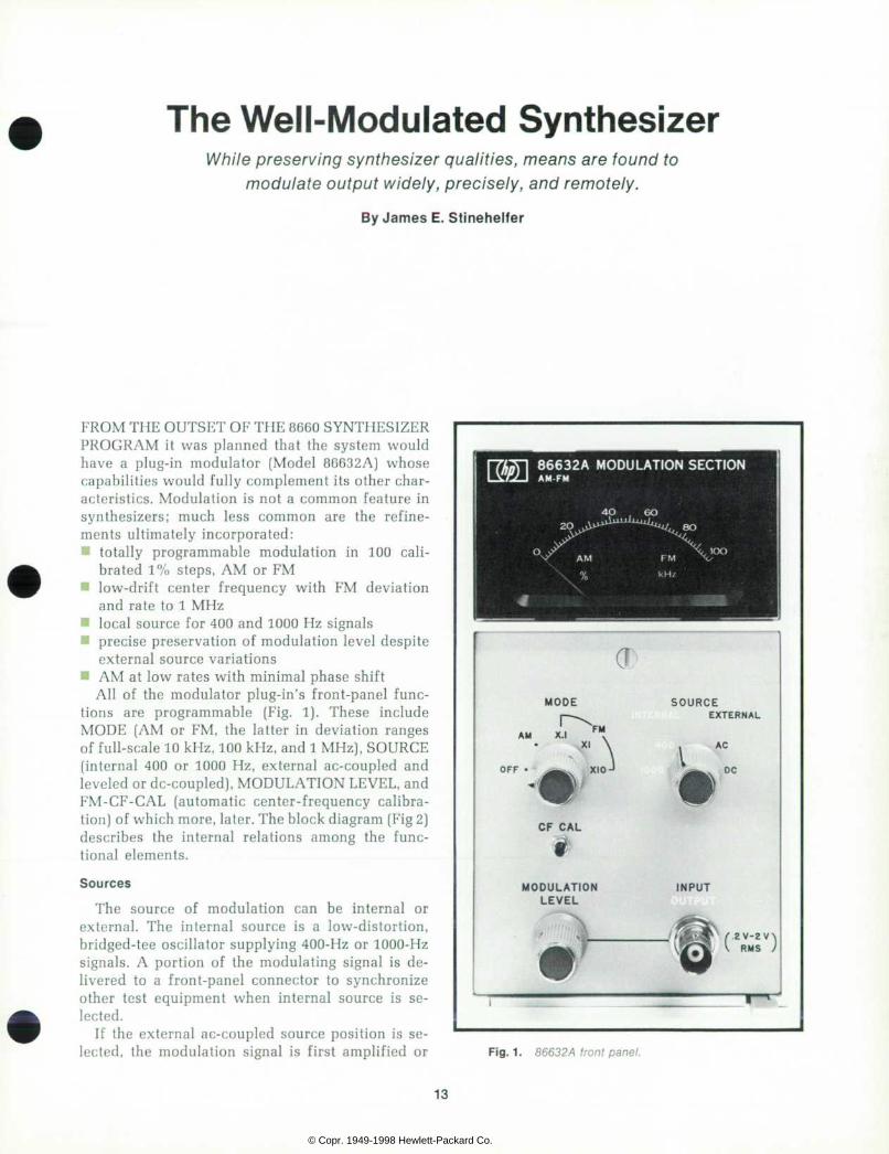
FROM THE OUTSET OF THE 8660 SYNTHESIZER PROGRAM it was planned that the system would have a plug-in modulator (Model 86632A) whose capabilities would fully complement its other char acteristics. Modulation is not a common feature in synthesizers; much less common are the refine ments ultimately incorporated: a totally programmable modulation in 100 cali
brated 1% steps, AM or FM • low-drift center frequency with FM deviation
and rate to 1 MHz • local source for 400 and 1000 Hz signals • precise preservation of modulation level despite
external source variations • AM at low rates with minimal phase shift
All of the modulator plug-in's front-panel func tions are programmable (Fig. 1). These include MODE (AM or FM, the latter in deviation ranges of full-scale 10 kHz, 100 kHz, and 1 MHz), SOURCE (internal 400 or 1000 Hz, external ac-coupled and leveled or de-coupled), MODULATION LEVEL, and FM-CF-CAL (automatic center-frequency calibra tion) of which more, later. The block diagram (Fig 2) describes the internal relations among the func tional elements.
Sources
The source of modulation can be internal or external. The internal source is a low-distortion, bridged-tee oscillator supplying 400-Hz or 1000-Hz signals. A portion of the modulating signal is de livered to a front-panel connector to synchronize other test equipment when internal source is se lected.
If the external ac-coupled source position is se lected, the modulation signal is first amplified or
8 6 6 3 2 A M O D U L A T I O N S E C T I O N A M - F M
<J
M O D E S O U R C E E X T E R N A L
A M X . I FM
OFF • "\ X I O J
AC
• DC
C F C A L
MODULATION L E V E L
INPUT
/ . 2 V - Z V \ R M S I
F ig . 1 . 86632 A f r on t pane l .
13
© Copr. 1949-1998 Hewlett-Packard Co.
F r o n t P a n e l
C o n t r o l s Logic
I D e c o d e r a n d
M u l t i p l e x e r
4 0 0 H z / lOOÓHz I n t e r n a l
Osci l la tor
R e m o t e l y C o n t r o l l a b l e
V e r n i e r A t t e n u a t o r
E x t e r n a l I n p u t /
O u t p u t
R a n g e A t t e n u a t o r F M x O . l
x 1 x 10
P h a s e Lock
T i m i n g Cont ro l
2 0 M H z V o l t a g e -
C o n t r o l l e d Osc i l l a to r
2 0 M H z R e f e r e n c e
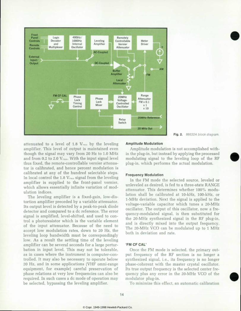
attenuated to a level of 1.8 Vâ„¢s by the leveling amplifier. This level of output is maintained even though the signal may vary from 20 Hz to 1.0 MHz and from 0.2 to 2.0 Wms. With the input signal level thus fixed, the remote-controllable vernier attenua tor is calibrated, and hence percent modulation is calibrated at any of the hundred selectable steps. In local control the 1.8 Vrms signal from the leveling amplifier is supplied to the front-panel vernier, which allows essentially infinite variation of mod ulation indices.
The leveling amplifier is a fixed-gain, low-dis tortion amplifier preceded by a variable attenuator. Its output level is detected by a peak-to-peak diode detector and compared to a dc reference. The error signal is amplified, level-shifted, and used to con trol a photoresistor which is the variable element of the input attenuator. Because of the need to accept low modulation rates, down to 20 Hz, the leveling loop bandwidth must be correspondingly low. As a result the settling time of the leveling amplifier can be several seconds for a large pertur bation in input level. This may not be tolerable, as in cases where the instrument is computer-con trolled. It may also be necessary to operate below 20 Hz, and in some applications (VHP omni-range equipment, for example) careful preservation of phase relations at very low frequencies can also be required. In such cases a dc mode of operation may be selected, bypassing the leveling amplifier.
F i g . 2 . 8 6 6 3 2 A b l o c k d i a g r a m .
Ampli tude Modulat ion Amplitude modulation is not accomplished with
in the plug-in, but instead by applying the processed modulating signal to the leveling loop of the RF plug-in, which performs the actual modulation.
Frequency Modulat ion In the FM mode the selected source, leveled or
unleveled as desired, is fed to a three-state RANGE attenuator. This determines whether 100% modu lation shall be calibrated at 10-kHz, 100-kHz, or 1-MHz deviation. Next the signal is applied to the voltage-variable capacitor which tunes a 20-MHz oscillator. The output of this oscillator, now a fre quency-modulated signal, is then substituted for the 20-MHz synthesized signal in the RF plug-in, and is directly mixed into the output frequency. The 20-MHz VCO can be modulated up to 1 MHz both in deviation and rate.
' F M C F C A L ' Once the FM mode is selected, the primary out
put frequency of the RF section is no longer a synthesized signal, i.e., its frequency is no longer phase-coherent with the master crystal oscillator. Its true output frequency is the selected center fre quency plus any error in the 20-MHz VCO of the modulator plug-in.
To minimize this effect, an automatic calibration
14
© Copr. 1949-1998 Hewlett-Packard Co.

cycle, FM CF CAL, has been included (Fig. 3] which momentarily interrupts the modulation and phase locks the 20-MHz VCO to a 20-MHz synthesized signal, stores an error correction voltage, and re turns to normal operation. This FM Center Fre quency Calibration cycle requires approximately five seconds and can be initiated from the front panel or may be programmed through the rear panel remote connector. The frequency error immediately after calibration is typically less than 100 Hz re gardless of the center frequency selected on the 8660A.
The 20 -MHz VCO The FM capabilities of the modulation section
are primarily determined by the characteristics of the VCO and its bias circuits. A significant part of the engineering accomplishment was obtaining si multaneously the linearity, stability, and sensitivity required. The basic oscillator uses a matched set of three hyperabrupt variable-capacitance diodes to tune a tank circuit over the required range of 19 MHz to 21 MHz. Careful selection of the operating bias voltage allows this excursion with a sensitivity of approximately 1 Hz/^V and nonlinearity less than ±2%.
The stability of the oscillator is mainly a func tion of the ability of the 'sample and hold' circuit used in the FM CF GAL cycle to 'hold' the correc tion voltage. The use of a special capacitor and MOSFET plus a 0.0 volt nominal bias voltage yields a time constant for the circuit on the order of 109
seconds. This translates to approximately a 2 Hz/ min drift rate. Further through careful temperature compensation, stability with temperature is typi cally 15 PPM/°C. After ambient temperature sta bility is reached all temperature-related drift may be removed by the FM CF CAL cycle (Fig. 3).
Mechanical Often the physical constraints placed on the me
chanical design of a plug-in result in severe com promises to ease of assembly, test, and service. The 86632A, however, aims to be an example of lack of compromise on such features. Hand wiring has been minimized through the use of a structural motherboard, a harness board, and a 16-wire ribbon cable with IC-type flat-pack connectors.
Board guides and extractors are color coded to establish position, polarity, and assembly number for each of five plug-in circuit boards. The rear housing, which provides thermal stability and RF shielding for the 20-MHz VCO, relay switch and phase lock mixer, can be pivoted away from the side frames allowing access to all components with out major disassembly. Within the rear housing a low-cost RF feedthrough was developed which eliminated three external RF cables and their asso ciated connectors by allowing board-to-board con nection through the inside partitions of the housing.
The entire package has sustained shock levels in excess of 200 G's without mechanical or electri cal failure.
T i m i n g One-Shot
( 5 s )
Phase Lock Mix-
i f f f i I ^ ^ ^ J B ' f l 2 0 M H z O u t
r a K P P N 2 0 M H z
f l i x e r R e f e r e n c e
Relay Switch
F i g . 3 . F M C e n t e r F r e q u e n c y Ca l ib ra t ion b lock d iagram.
15
© Copr. 1949-1998 Hewlett-Packard Co.

The 86631A Auxiliary Section The auxiliary section is provided for those with
limited modulation needs. It performs all necessary system interconnections and also provides direct access to the RF section level control. Through a front panel BNC connector all AM capabilities of the RF section may be exercised (though remote operation is not possible). The sensitivity of the input is 1 Vrms/100% and percent AM is linear with input level over this range. The maximum frequency and modulation depth obtainable is dependent on the RF section installed.
Perhaps one of the primary uses of this plug-in will be as a basic housing for those who wish to build special-purpose modulation sections.
A c k n o w l e d g m e n t s The modulation section had been a child of many fathers when I was assigned its development. John Hasen did the preliminary block diagram and also acted as an invaluable consultant throughout the entire project. Art Bloedorn did the initial design of the 20-MHz VCO and several of the 8660A/B oscillators. Bob Gallien and Brad Stribling both con tributed design approaches which were eventually used. Jim Fleming did all of the product design and contributed greatly to the entire project.
James E . S t inehe l fe r Jim St inehel fer came to Cal i forn ia 15 years ago, f rom Michigan. He was a par t - t ime employee at HP even as a Stanford undergraduate, and he became a fu l l t ime engineer soon after taking his BS ¡n EE in 1965. His dut ies were successive ly in charge of env i ronmenta l test ing, then in synthesizer design. J im went on, under the HP Honors Program, to take an MBA at nearby Santa Clara Univers i ty , meanwhi le marry ing and star t ing a fami ly . He had to g ive up his Cessna 170 on the arr ival of the second youngster, but he st i l l f l ies, rent ing a p lane now and again for long weekends in p laces l ike the Grand Canyon. Most fa l l weekends you can f ind J im in the f ie lds hunt ing wi th h is Labrador Retr iever 'Gypsy. '
S P E C I F I C A T I O N S HP Model 86632A
AM/FM Modu la t ion Sec t ion
I N T E R N A L M O D U L A T I O N A M :
R A T E : 4 0 0 H z a n d 1 k H z  ± 5 % . D E P T H : 0 t o 1 0 0 % ( o r m a x i m u m s p e c i f i e d f o r R F u n i t i n s t a l l e d ) . M E T E R R A N G E : 0 t o 1 0 0 % . M E T E R A C C U R A C Y :  ± 5 % F S .
F M : R A T E : 4 0 0 H z a n d 1 k H z  ± 5 % . D E V I A T I O N : 0 t o 1 M H z p e a k
( o r m a x i m u m s p e c i f i e d f o r R F u n i t i n s t a l l e d ) . M E T E R : 3 r a n g e s â € ” 1 0 k H z , 1 0 0 k H z , 1 M H z . M E T E R A C C U R A C Y : Â ± 5 % F S .
E X T E R N A L M O D U L A T I O N I n p u t L e v e l R e q u i r e d , a c - c o u p l e d m o d e : 0 . 2 V t o 2 . 0 V . I n p u t L e v e l R e q u i r e d , d e - c o u p l e d m o d e : 1 . 8 V â € ” s  ± 5 0 m V . I npu t Impedance : 600 Ãà . A M : d c t o 1 M H z i n d c m o d e , 2 0 H z t o 1 M H z a c m o d e .
R a t e , d e p t h , a n d m e t e r a c c u r a c y s a m e a s I N T E R N A L .
F M : R a t e d c t o 1 M H z i n d c m o d e , 2 0 H z t o 1 M H z a c m o d e . D e v i a t i o n , m e t e r r a n g e s a n d a c c u r a c y s a m e a s I N T E R N A L .
D I S T O R T I O N : P a r t i a l l y d e t e r m i n e d b y d i s t o r t i o n o f e x t e r n a l m o d u l a t i n g s i g n a l , w h i c h m u s t b e u n d e r 0 . 3 % t o m e e t R F S e c t i o n d i s t o r t i o n s p e c i f i c a t i o n s , e . g . < 1 % @ 3 0 % A M , < 3 % @ 7 0 % A M , a n d < 5 % @ 9 0 % A M w i t h 8 6 6 0 1 A 0 . 1 - 1 1 0 M H z R F S e c t i o n .
R E M O T E P R O G R A M M I N G F U N C T I O N S : A l l 8 6 6 3 2 A f r o n t p a n e l c o n t r o l s a r e p r o g r a m m a b l e
t h r o u g h t h e 8 6 6 0 A o r 8 6 6 0 B m a i n f r a m e p r o g r a m m i n g i n t e r f a c e . R e s o l u t i o n o f R e m o t e M o d u l a t i n g S e t t i n g : S t e p s o f 1 / 1 0 0 o f t h e
r a n g e s e l e c t e d . A c c u r a c y o f R e m o t e M o d u l a t i o n S e t t i n g : Â ± 5 % o f s e t t i n g w h e n
u s i n g a c o r i n t e r n a l s o u r c e s . G E N E R A L
S I Z E : P l u g - i n f o r 8 6 6 0 A o r 8 6 6 0 B m a i n f r a m e . W E I G H T : N e t , 7 I b ( 3 , 2 k g ) . P O W E R : F r o m 8 6 6 0 A o r 8 6 6 0 B m a i n f r a m e . P R I C E : $ 9 0 0 . 0 0 .
M A N U F A C T U R I N G D I V I S I O N : M I C R O W A V E D I V I S I O N 1 5 0 1 P a g e M i l l R o a d P a l o A l t o , C A 9 4 3 0 4
HEWLETT-PACKARD JOURNAL JANUARY 1972 volume 23 • Number 5 T E C H N I C A L I N F O R M A T I O N F R O M T H E L A B O R A T O R I E S O F H E W L E T T - P A C K A R D C O M P A N Y 1 5 0 1 P A G E M I L L R O A D , P A L O A L T O , C A L I F O R N I A 9 4 3 0 4 U S A .
Hewle t t -Packa rd S .A . 1217 Mey r i n †” Geneva . Sw i t ze r l and • Yokagawa-Hew le t t -Packa rd L td . . Sh ibuya -Ku . Tokyo 151 Japan
Editor: R. H. Snyder Editorial Board: R. P. Dolan, H. L. Roberts, L. D. Shergal is Art Director: Arv¡d A. Danielson Assistant: Erica R. Helstrom
© Copr. 1949-1998 Hewlett-Packard Co.