19960613006 - ntrs.nasa.gov
TRANSCRIPT
NASA
Contractor Report 4704
Army Research Laboratory.
Contractor Report ARL-CR-287
Computerized Design and Analysis ofFace-Milled, Uniform Tooth Height,Low-Noise Spiral BevelGear Drives
EL. Litvin and X. Zhao
V___=_ ___
GRANT NAG3-1607
JANUARY 1996
19960613006RESE_,RCHL_DO_¥ORY
AIJA 3()'#_(,_,
NASA
Contractor Report 4704
Army Research Laboratory
Contractor Report ARL--CR-2g7
Computerized Design and Analysis ofFace-Milled, Uniform Tooth Height,
Low-Noise Spiral BevelGear Drives
EL. Litvha and X. Zhao
University of llli_wis at Chicago
Chicago, Illinois
Prepared forPropulsion DirectorateO.S. Arm), Aviation Systems Commandandlewis Research Center
under Orant NAO3-1607
Nttlotl Aaron_Ucs _dSp_e Aat_Itrtt©n
tnfccm_JonPro_'em
Ar_Ajfl,s_,r,_,
[ I [_ III I
Abstract
A new method for design and generation of spiral bevel gears of uniform tooth depth
with localized hearing contact and low level of transmission errors is considered.
The main features of the proposed approach are as follows:
(I)
(2)
The localization of the be.-Lring contact is achieved by the mismatch of the generating
surfaces. The bearing contact may be provided in the longitudinal direction, or in the
directionacrossthe surface.
The low level of transmission errors is achieved due to application of nonlinear relations
between the motions of the gear and the gear head-cutter. Such relations may be
provided by application of a CNC machine. The generation of the pinion is based on
application of linear relations between the motions of the tool and the pinion b_dng
generated. The relations described above permit a parabolic function of transmission
errors to be obtained that is able to absorb almost linear functions caused by errors of
gear alignment.
A computer code has been written for the meshing and contact of the spiral bevel gears
with the proposed geometry. The effect of misalignment on the proposed geometry hu also
been determined. Numerical examples for illustration of the proposed theory have been
provided.
AI)A'_O'_r!,(,,,

Section
TABLE OF CONTENTS
1 Introduction 3
2 Method for Generation of Conjugated Pinion-Gear Tooth Surfaces 4 ..-
3 Generation of Gear Tooth Surfaces
4 Machine-Tool Setting_ for Pinion Generation 12
5 Equations of Pinion Tooth Surfaces 13
0 Computerized Simulation of Meshing and Contact 22
7 Numerical Example 27
8 Conclusion 31
9 Directions for TCA Program Use 32
Figures 38
2
ADA i_U'_SC.,c.,
1 Introduction
The resezxch project is ddrected at the design and generation of face-refilled spiral bevel gears
with the following features:
(1) The depth of the teeth is uniform which means that the height of the teeth is constant.
(2) The gear tooth surfaces contact _.h other at every instant at a point. Thus, the
betting conlac_ is localized a_d therefore the sensitivity of the gesrs to rnisalignmeat
is reduced.
(3) The surface contac_ under the load is spread over an d_ptica_ area, whose center is the
theoretical contact point. The set of instantaneous contact ellipses form the bearing
contact. The developed methods o5 synthesis provide two types of bearing contact that
may be directed: (i) in the longitudinal direction, or (ii) across the tooth surface.
(4) Two generating surfaces, E: and Z_, are used for the generation of the pinion and
the gear tooth surfaces Z1 and E_, respectively. The dimensions of the inszant_.neous
contazt ellipse depend on the bad applier1 to the gear drive, and on the chosen relation
between the curvaturesof_he generatingsurfaces.
(5)Gear misalignment may cause transmission errors of a high level and of su_ s s,_
that a high level of vibration wi]_ be resulted. The developed appro_h provides at each
cycle of meshing a pred_igned parabolic function that will absorb the transmission
errors caused by misalignment. The cycle of meshing is determined as
(I)
--- - ' [ I I I' I I JJ i'a ,. ii
where _a and N1 are the angle of pinion rotation and the pinion tooth number.
2 Method for Generation of Conjugated Pinion-Gear
Tooth Surfaces
Kinematic R.dations
We willconsiderinitiallyan irr_gJnaryprocessforgenerationwhen the pinion_nd gear
toothsurfaceswillbe ge_cratedsimultaneously.Such an approach willpermitone toobtain:
(i)irnporta_atkinem,',+ticrelationsto be executedon the CNC machine,_nd (ii)to visualize
the possibilityto ohtaintwo kindsof the localizedbearingcontact.In reality;the pinion
nnd gear tooth s c_ c_ are generated separately as it is discussed in the following sections.
We start wi_i, ,. c_e when the axes of the pinion and the gear form art angle of 90*
(fig. 1). However, the developed approach is applicable for gear drives whose shaR angle
differs of 90° . The pinion and the gear during the process for generation perform rotation
about axes Xa, and X_, respectively. Two rigidly connected generating surfaces, Zt and E,,
perform rotation about the Z,, axis. Surfaces Et _nd E_. generate the pinion and gear tooth
surfaces E1 and E2, respectively. The relation between the angular velocities _(;) and _{')
is represented by the equation
o;(¢)M_---S = sin-r_ (2)
where "rl is the pitch angle of the pinion. The _rarrsmission function of the gear drive
must be obtained for each cycle of meshing as the sum of the theoretical linear function and
the predesigned parabolic furtction as shown in fig. 2. We may represen_ the transrndssion
function at the first cycle of meshing by the equation
A[)A :3U'_S¢,6
• - + I I II1_111 I I I I III I I IIIIII IIII

Differentiating equation (3), we obtain that
N:
Taking into a_:ount (_ee equ_.tion (2)) that
we obtain that
(3)
(4)
¢_= _---_-_ (5)sin _
_=. _ _o ." _'_ )_J_._n_, - t_ (6)
= (E- (7)
Confide_ng _c and _ as the input parameters, we may obtain _(l) _1, ¢2, and _(2)
using equations (2), (5). (6), and (7), respectively. Since _2(¢_) is a nonlinear function,
the seneration of the gear requires application of a CNC machine for the execution of the
nonlinear function _2(¢_).
Note: The ratio of wO) and _0) (_(0 - _)) is constant during the proe.ess of pinion
generation, the instantaneous axis of rotation is directed along the X_ axis, and the pinion
axode (in the process of meshing of the pinion tooth surface _1 with the genera_,ing surface
E_) is a circular cone with the pitch angle
N1
ADA309566

.... I- II II .....
The axode of the generating surface is the plane Z_ = 0 that is tangent to the pinion
axode.
The ratio of angular ,,,docities _,, and _ is not const_t. Therdore, the axode of
gear 2 being in meshing with the pinion and the generating surface _;¢ is not a circular com.
Generating Surfaces
It was mentioned above that two rigidly connected generating surfaces E, ",nd E¢ are
applied for the generation of the pinion and gear, respectively. Two pairs of surfaces Et and
Y_ are applied go provide two types of bearing contact for the generated pin/on and gear
tooth surfaces _;l and E_..
Case 1:
The two generating surfaces are _ cone E, and a surface of revolution _. The surfaces
are in ta_gency a|ong a circle _nd are rigidly connected ea_ to other in the process for
generation (fig. 3). Surfaces _;_. and E2 are in liar taagency along lines L_ while being in
mesh in the process for generation. Similarly, Et and E1 are in line contact, along lines L_l
(not shown in fig. 3). HoweveL. instantaneous contact lines L_ and Ltl do not coincide
each with other but are in t_ngency at a point that belongs to the circle L,_. This means
that surfaces El and _2 are in point contact, at every instant that moves along the circular
arc L_t in the process of meshing. The p_,th of contact L_ (_nd the beating contact) has a
longitudinal direction.
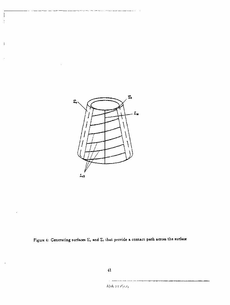
Case 2:
The generating surface_ Ec and _ are rigidly connected cones that, a_:e in tangency along
t'_eir common generatrix L_ (fig. 4), Only contact lines Lq between surfaces _ and _2 are
shown in the figure. Each contact line L_ and the respective line L_t are in tangency a_ the
respective print of the generatrix L_. This point is the current point of tang_ncy of gear
ADA 309r_(,b
tooth surfaces Ex and E2.
The generating surfaces Et and Ec are the surfaces of two head-cutters that eae applied
for the generation of the pinion _Lnd the gear, respectively. In reality, the head-cutters are
provided with straight line blades or with circul_ arc edge blades but not with surfaces. Such
blades are rot:,ted about the head- cutter axes to form the generating s_faces. The angular
velocity of rotation of blades must provide the required velocity of cutting or grinding, but
is not related with the process for generation of the pinion or gear tooth surfaces.
The head-cutter is installed on the cradle of the cutting machine and then performs with
the cradlethe rotationabout the Z,_axiswith the angularvelocity.,(_)= w (_).Detailsof
the settingsofthe he_d-cutteron thecradlearediscussedinsections3 and 4.
3 Generation of Gear ToothSurfaces
Applied Coordinate Systems and Machine-Tool Settings
We have considered in Section 2 an imaginary, process of generation of conjugate pinion-
gear tooth surfaces based on the assumption that the surfaces will be generated simultane-
o_ly. In reality, the pinion-gesr tooth surfaces are generated separately, as it was mentioned
above.
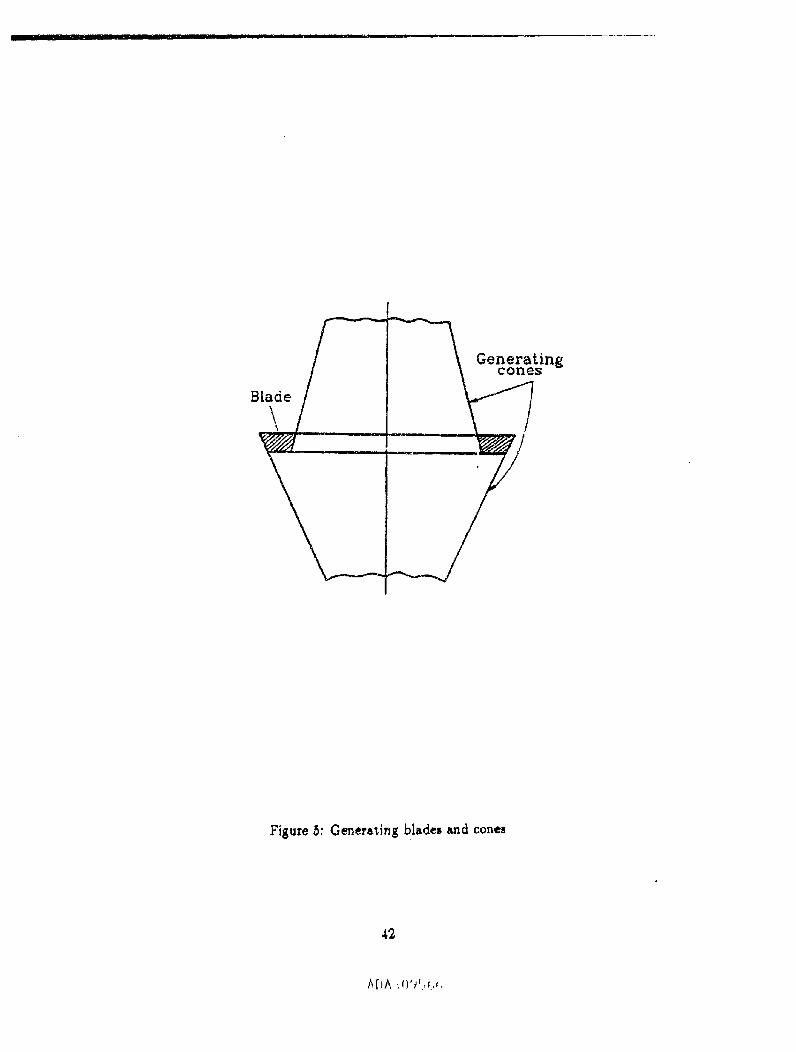
This section deals with gea_ generation and the applied machine-tool settings. The gear
tooth surfaces are generated by a head-cutter that is provided with straight.line blades (fig.
5). Both sides of the gear tooth are generated simultaneously. The blades are rotated about
the head-cutter axis. The edges of rotated blades form two circular cones as the generating
surfaces us'ed for the manufacturing of the gear.
Hencefo,'th, we will apply the movable coordinate systems S¢2 and 32 that are rigidly
AI_)A3_J95_,(.,
'1
connected to the cradle and the gear, respectively (fig. 6). The fixed coordinate system $,_
is rigidly connected to the cutting _ine. C_ordtnate system Sa2 is an additional fixed one
and is rigidly connected to the coordinate system S,_. The orientation of S_ with respect
to S_ is determined by angle _/_ = "y- "h, where _/t is the pitch angle of the pinion pitch
cone. During the process for generation, the cradle and the ge,_ perform related rotation_
about the X,n-axis and the Xd:-a_is, _e_ectiveJy. The current e_ugles of rotation of the
cradle and the ge_ are de,ignited by _ and _, that _re related by equa'don (6) in which
we change the designation of _ for _,_. This relation p_ovides the predesigned parabolic
function designated for the absorption of transraission errors caused by misalignrnent.
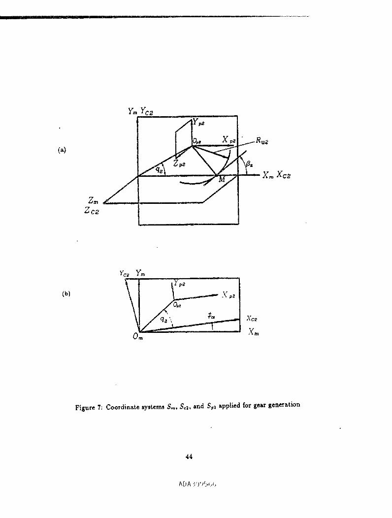
The ingtailment of the head-cutter is shown ir_ fig. 7(a). Fig_r_ 7(a) shows the position
of the cradle when $q = 0, and the coordinate system S_ coincides with S=. Coordin_,te
system S_ is an additional coordinate system that is rigidly connected to S,,, and performs
rotation with S_ as shown in fig, 7(b). Coordinate axes of Sm a_d $_2 bare the same
orientation. Axis Zn is the axis of the head-cutter (see below). The instaJlmen_ of the
head-cutter in S_2 may be determined by"the parameters of the triangle with the spexes
Oq, 0_, and M, where M is the mean point, of the cone distance of gear 2 (fig. 8). The
installment of the head- cutter in coordinate system S_ may be determined as well by Ha
a_d Vc (fig. 8), where
HG = A,_ -/_2 sin 82
Vc -/¢_2 cos _
Here, B_ = 1_'_1 is the nonfinal r_dius of the head-cutter (fig.
(9)
and _ is the spiral angle of the gear. Alf_'native coupled parameters of insts.llment, S,_ --
l]_'_'_ ] and q2, HG end Vo, _e relat, ed by the equations
8
.... i_i1._,11 i i i, ,11 i i I I II I I [I III II I
S,, -" (H_ + V_)°'s (11)
q_--tan-(_--2) (12)G
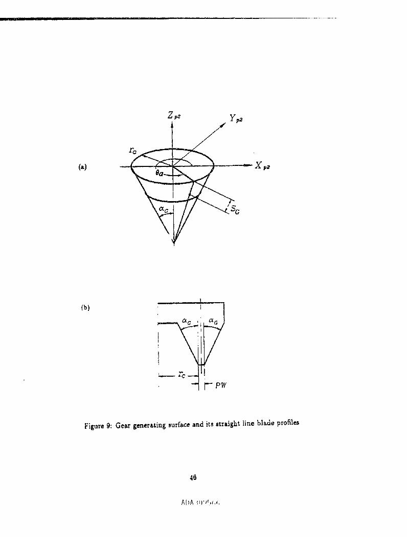
Equations of Gear Generating Surfaces
We h_ve mentioned before that two cones as generating _urfac._ are treed for cutting c(
the space of the gear (fig. 5). Fig. 9(b) shows the cutting blade, and £g. 9(a) shows one
of the generating cone_. The generating cone is formed by rotation of the blsxl_ _lge about
the Zm axis. The equations of the cone are represented in S_ as
(r, -- So sin _) cos0a ]rn(So,0_)= (r, Sasinao)sin0_ j (13)-- SG C_8 C_G
where 8G and S'G (fig. 9(a)) are. the surface coordinates (the Gausian coordinates); aO is
the blade angle; r_ is the radius of the head-cutter that is measured at the tip of the blade.
Parameters re and Ru2 are related as follows
PWr: = R,,2± _ (14)
2
The upper and lower signs in {14) correspond to the gear concave and convex sides.
Equations (13) may represent both generating cones, if we will use the rule of signs in
equation (14), and consider that c_G > 0 and c_o < 0 correspond to the gear concave and
convex sides, respectively.
The unit normal to the gear generating surface is represented by the equations
n_ _ N_ Or_ Or_= P%I' = _ ×
Equations (14) and (15) yield
(1_)
A[.)A_U')_.,c,_.,

_(Oa) =r _ cosaG cos _G ]
- cosao sin0_Jsin aa(16)
Algorithm for Derivation of Gear Tooth Surfaces
The derivationofgeartoothsurfaceE_ isba,edon the followingprocedure:
Step 1:
Initiallywe derivethefamilyofgeneratingsurfacesin S_ usingthe matrix equation
r2(Su, _a, _,) = M_r.(So, 6o)- M2a_ ($2)M,2..M,=¢,(d_2)M_mrm (Sa, 00) (17)
where _ and dr axerelatedby equation (6).
Step 2:
Then, we derivetheequation of meshing betvgeenthe gear and the generatingsurface
that we represcr:t ;_nthe form
_ .v(2_)=/(sc, eo,_,,)= 0 (is)
where n(_N) is the unit normal to the generating surface E_,, and v (_.2) is the relative (sliding)
velocity. The scaler product (n (_) •v {_')) may be represented in any coordinate system. In
our derivations, the scaler product is represented in S,_.
Note: we may represent as well the equation of meshing in the form
N_)._ = 0 (19)
where N (_) is the normal but not the unit normal to the generating surface.
Equations (17) and (18), considered simultaneously, represent the gear tooth surface as
the envelope to the family (17) of generating _urface_.
10
A[_h-_'0 9 _-_(.(,
--_ I I I I I
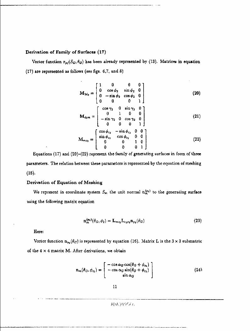
Derivation of Family of Surfaces (17)
Vector function rw(Sa, 0_) has been already r¢_resented by (13). M_tric_ in eq_tion
(17) are represented as follows (sev figs. 6,7, _.nd 8)
M2d_ -----
Md_n =
1 0 0 0
0 cos_b2 sin_b2 0
0 -tin¢2 cos_ 00 0 0 l
cos'T2 0 sin_,_ 00 1 0 0
-sinff_ 0 cos_,2 00 0 0 1
cosec2 -sin_ 0 0
sin_ cos_ 0 00 0 1 0
0 0 0 1
(20)
(21)
(22)
Equations (17) and (20)-(22) represem the family of generating surfaces in form of three
parameters. The relation between these parameters is represented by the equation of meshing
0s).
Derivation of Equa*ion of Meshing
We repr_ent in coordinate system S= the unit normal n_ _ to the generating surface
using the following matrix equat, ion
n_ _(0c, $2) = L._ L,_, nr, (0a) (23)
H_'e:
Vector function n_(0a) is represented by equation (16). Matrix L is the 3 × 3 submatrix
of the 4 × 4 matrix M. After derivations, we obtain
- cosao cos(Co.+ $_) ]n_(0c;, *_) = cos a_ sin(0a + _,)
sin aa
11
(24_
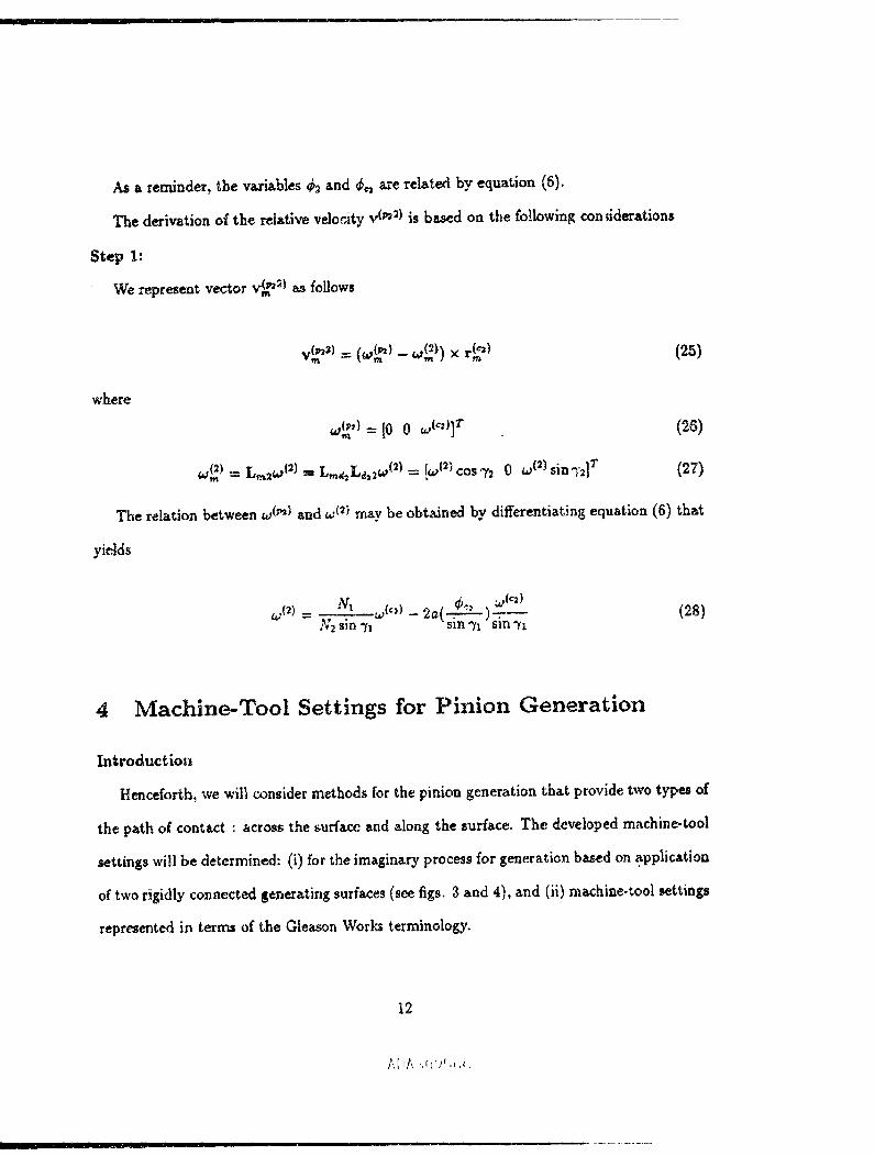
As a reminder, the variables d2 and _,_ a_e related by equation (6).
The derivation of the relative veioaty v (_;) is based on the following con ;iderations
Step 1:
We represent vector v__2) an follows
where
(zs)
,,,L"_= lOo ,,,("_]_ (26)
w_) = L,,a_a{ 2) -- L,nd_La,_a (2) = !_atz) cosT: 0 to t') sinq':] T (27)
The relation between w (w} and _(') may be obtained by differentiat3ng equation (6) that
yields
4 Machine-Tool Settings for Pinion Generation
Introduetio_
Henceforth, we will consider methods for the pinion generation that provide two types of
the path of contact : across the surface and along the surface. The developed machine-tool
settings will be determined: (i) for the imaginary process for generation ba_ed on .application
of two rigidly connected generating surfaces (see figs. 3 and 4), and (ii) machine-tool settings
represented in terms of the Ghason Works terminology.
12
/,,[ IA .;(1'/c ,_ ,_,
,, ,. r , , . III --...._._I_ i II I
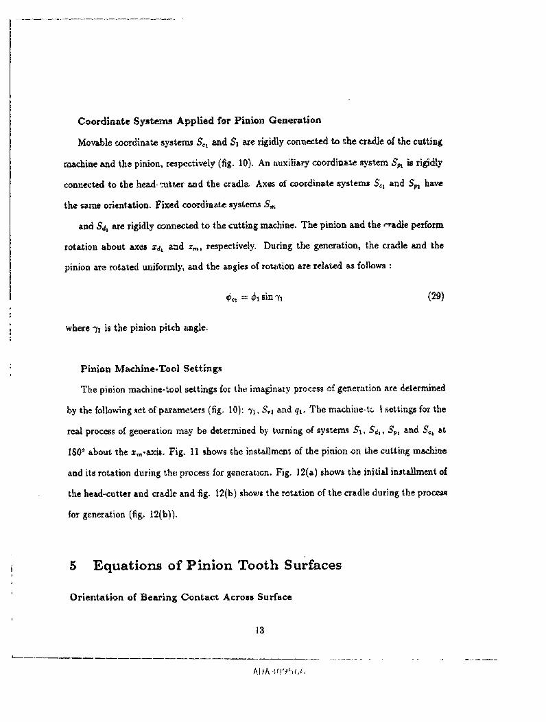
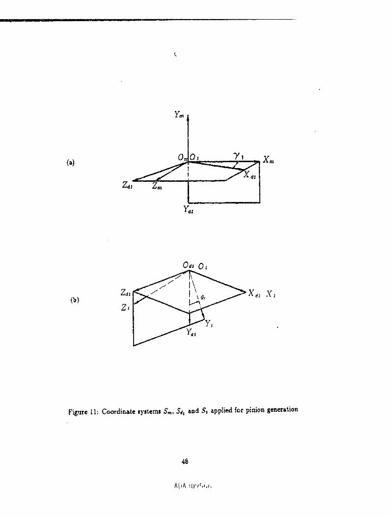
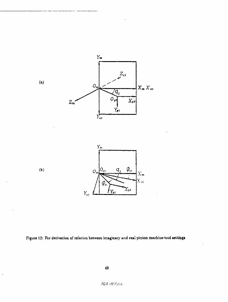
Coordinate Systems Applied for Pinion Generation
Movable coordin_ systems ,_ and Sl ate rigidly connected to the cradh of the cutting
ma_ine and the pinion, respectively (fig, 10). An _uxiliary coordinate system S_ is rigidly
connected to the head-=utter and the cradleo Axes of coordinate systems So, and Spj have
the same orientation. Fixed coordinate systems S,_
and Sj, ate rigidly connected to the cutting machine. The pinion and the c_adle perform
rotation about axes zdx aud z,_, respectively. During the generation, the cradle and the
pinion are rotated uniformly, _ud the angies of rot¢_tion are related as follows :
_c_ -- _1 sin71 (2g)
where 7z is the pinion pitch angle.
Pinion Machine-Tool Settings
The pinion machine-tool settings for the imaginary process ef generation are determined
by the following set of parameters (fig. 10): 7t, S,1 and q,_ The machiae-t_, i settings for the
real process of generation m_y be determined by turning of systems $1, S_, Sp, and S_, at
180° 0.bout _he x,,-axis. Fig. 11 shows the installmem of the pinion on the cutting machine
and its rotation during the process for gener_tlon. Fig. 12(a) shows the initial installment of
the head-cutter and cradle and fig. 12(b) shows the rotation of the cradle during the proc_.._
for generation (fig. 12(b)).
5 Equations of Pinion Tooth Surfaces
Orientation of Bearing Contact Across Surface
13
AI}A ::{!'?_2,_,_,

| .= ..... ! • ,i r
The mentioned type of bearing contact ia provided by _pplication of two rigidly connected
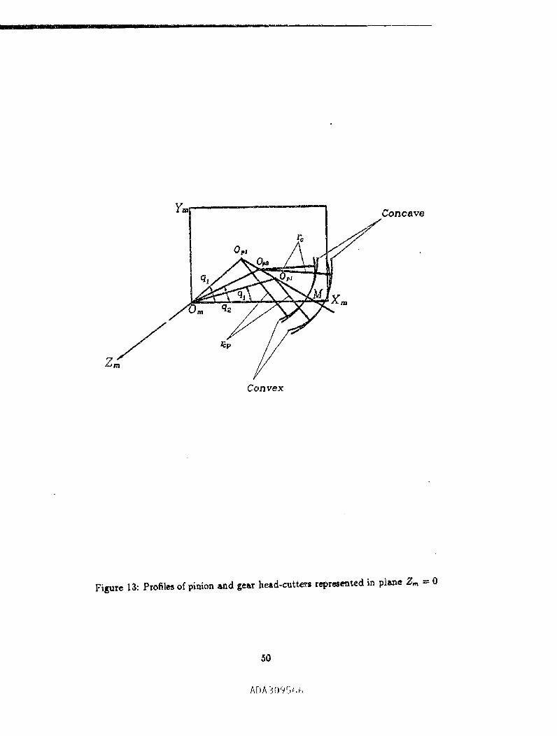
circul_ cones that generate the gear and phaion tooth surface, respectively (fig. 4). Fig. 13
shows the cross sections of the surfaces of the pinion and gear head-cutters in plane z_, ffi 0
when the cradle is at the initial position that is determined with 6¢, = 0, and the coordinate
systems 5'_: and S,_ coincide each with other (fig. 10(b))o
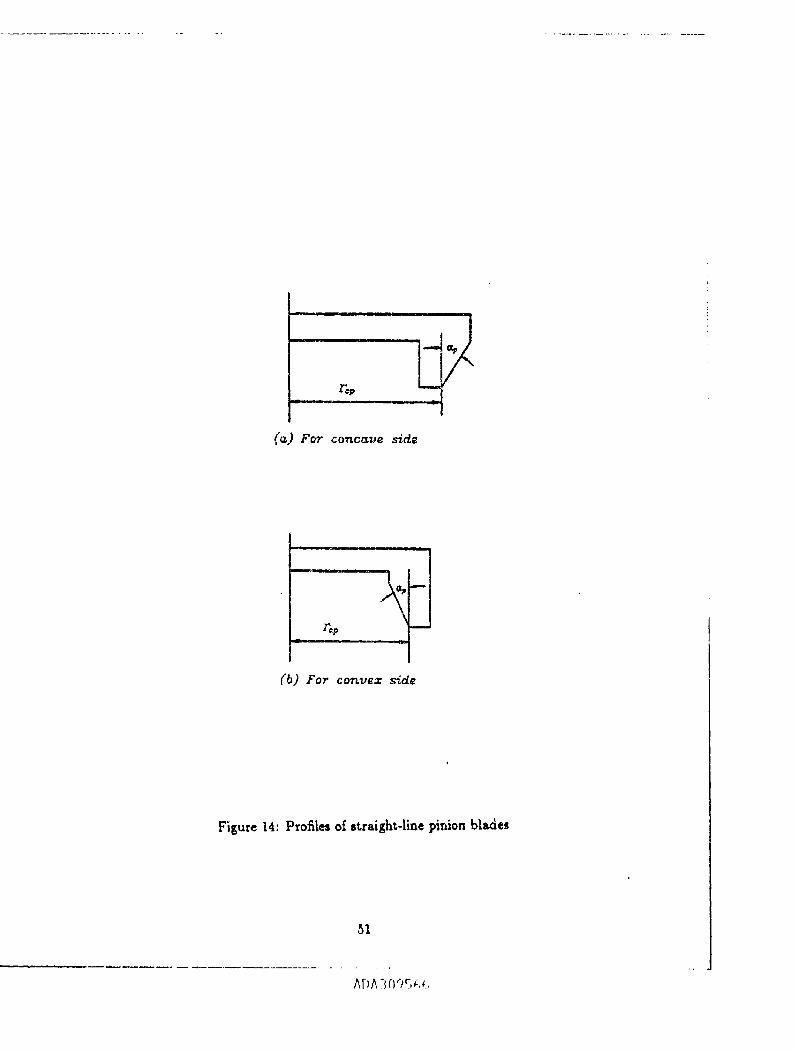
Fig. 14 shows the profiles of the cutter blades used for the generation of the pinion
concave side and convex side surfaces, respectively. Fig. 15 shows the generating surface
(cone) in system Spl. The derivation of the generated pinion tooth surface is based on the
following procedure.
Step 1:
The head-cutter generating surface is represented in Spl as
(r_ - Sv sinap) cos 0_
- S, sin av)sin0 --,_ COS o_
1
(30)
Here, r_, is the point r_ius (fig.
considered as positive and negative when the pinion convex and concave tooth surfac._ are
generated, respectivdy. Parameters Or and S_ are the head-cutter surface parameters.
The unit normal of the head-cutter generating surface is repr_enged in Sp_ as
14), _p is the blade angle. The sign of _rp should be
Equations(30) and (31) yield
Step 2:
-cosctp cos 0p ]nt_ -" -cosctp Sin 0t
sin ap
(32)
14
AI_A_ 0"_.;_,¢,
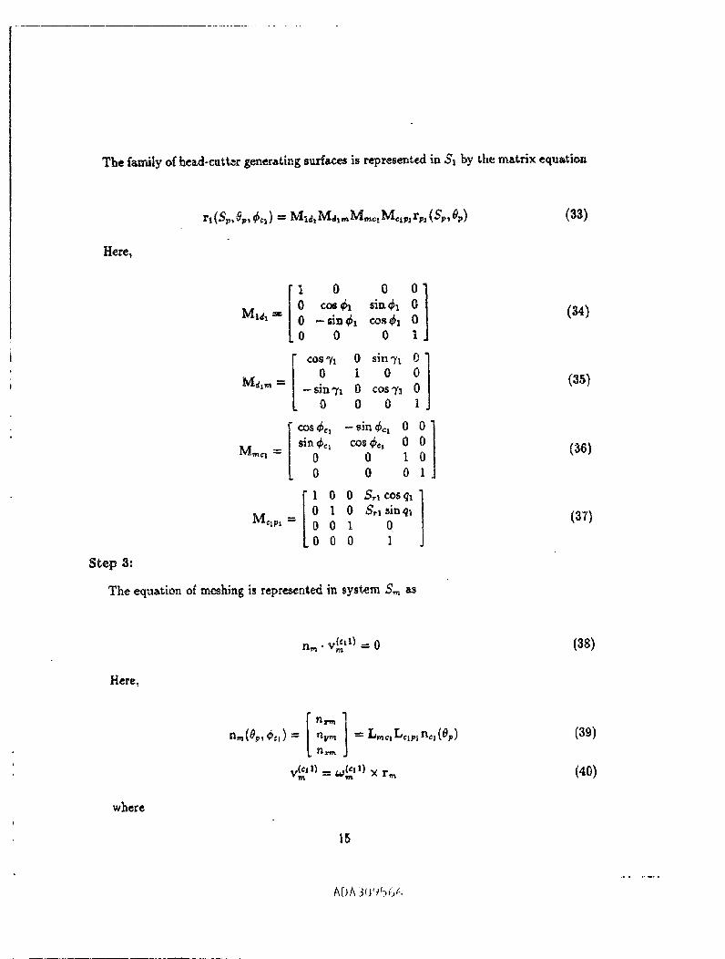
The f_mily of hcad-cutte.r generating surfaces is represented in S, by the matrix equation
Here,
(33)
Mld_ --.v.
Mglra m
Mine] "_
Mclp_ -
1 0
0 cos_h
0 - sin@I0 0
COS _/I
0
- sin_i
0
sin _0
0
1 0 0
010001
0 0 0
°°1siad_ 0cos ¢_1 0
0 1
0 sin'?l 01 0 0
0 cos T_ 00 0 1
- sin _ 0 0
cos @_, 0 00 i 0
0 0 1
,-Q'T_COS ql l
S,1 sinql01 ]
Step _:
The equation of meshing is represented in system S_ as
(a4)
(35)
(3e)
(37)
Here,
n,_•v_ tl)---0 (38)
where
I ]RJrm
v_ '')= w_") x r_
15
(39)
(40)
ADA 3(.vp_)6(-,

II'I _ I ill I 'II
-S_ sina, co<e, + ./,. ) + ,-_co._(e_+ 4,o:)+ S,_cos(,0, + q_)]= --,5'_ sin aj, sin(e v + _**) + r_ sin(@_ + Se. ) + S,j *in(Set + qt) ]Ueing the designations
(41)
we obtain
ro sin(0v + _,_) + S,x sin(S,. + qt) f (4_.)
rcrL ---
-$, eia_ cos@v+ ,,_) + B, ]-$,, _in o_v sin(Op + d,., ) + B_ ]-Sp COS Ot_
O-'c_ _1 sin q't
Then, we obtain that (since w, t = _t sin _x)
][_vtco*vt]= O0
(43)
(44)
[ o ]v_ '_) = _'*) × r_ = S_ cos% cos-t,-S, sin av sin(0_ + ¢¢t ) cos'/1 + 8_ cos _.t
We have assumed not loosing the geaerality of the approach that It, ll = I.
The equation of meshing yields
(4s)
or
n_,_S_co, ,_ cos-n - n_=S_sin a_ sin(O_ + ._,,) cos "n + a,_B2 cos _t = 0 (46)
Step 4:
'S_(O,¢_,:) = ___..___._ -n,,,,B_n_ cosa, - n,,,, sm a, sin(O,,+ ,0, ) (47)
16
Alia ?!r_9(,_-,

The envelope to the rarely of generating surfac_ m_y b_ repr_en_d in two p_ameter
form if we dindnate in equati,,n (33) parameter S_ using equation (47).
Orientation of Rearing Contact in Longitudinal Direction
The mentioned orientation of the be_xing contact can be adfieved by application of
generating surfaces shown in fig. 3. The profiJes of the blades of the head-cutter used for
the generation of the pinion are shown in fig. 16.
The derivation of the equations of the pinion tooth surface generated by a h_ad-cutter
with circular arc blades is based on the foLlowing procedure:
Step h
The coordinates of the center of the blade c_rcular arc for the concave side axe represented
by the following equations (fig. 16) :
where _ = r_,,_ = R1
F.,quation (48) yields the following equations for the coordinates of center C'l
(48)
Step 2:
x(c,I ffiU-o_1"i° = r_,-/_,cosa_ ]- _L'7_•jo---0= _--_6_,•ko = -R, sinap
(49)
The position vector o£ a carrent point of the circular arc is represented in S'o by the
equation (riga 6)
oD-A= _Z% + ,L_-j= DV_ + R,.o (50)
17
ADA _075<,<,
m i i ....
where
a.= o -anxdr (51)
is the unit normal to the circular arc that is represented in 5o.
Step ,._:
The he_-cutter surface is a surface of revolution that is generated while the circular
ate is rotated about the axis of the he_d cutter. The head-cutter surface is represented in
c.oordin_te system S_ as follows
__c,_ (52)rpl ----rb, +Rln_
rio,)= Lp,or_c_)
is the position vector of point C_ that is repre_euted in St
lie1 _ LMona
is the unit normal to the generating surface that is represented in Sp,
(53)
(_4)
cosOp -slnO r O]L_,o= sinO_ cosOp 0 (55)
0 0 1
Step 4:
For the following derivations, we represent the surface of the head-cutter in coordinate
sys_,em S_ (fig. lO(b)). We may use for this purpose the lollowing vector equation
_c_) (S6)
18
AfOA3095_,6
H_, (fg. 10(b))
= S.,[co,q, sinq, 0]T (57)
r_ *_= L,_c,r,, (58)
Step 5:
n., = I,,,,a,a_ (59)
[cos¢_ -sin¢_ O]L,,,c,= sin¢o cos,h 0 (_)0 0 1
The pinion tooth surf_w_ is represented in $1 a.s the emveJope to _he family of the head-
cutter surfaces that is generated in coordinate system $1. The equation of _,he family of
surfaces is as follows :
rl(_l, $p, 6_ ) "- M1_(¢I)Md_,_ r,_(gl, 0_, ¢,, ) (61)
As a reminder, angles ¢c, mad ¢1, angles of rotation of the cradle and _he pinion, are
related by the equation
¢,, = _1 sin-n (62)
Step fi:
The envelope to the family of surf_c_ is determined by equation (61) and the equation
of meshing that we represent as follows
The final e×pression of the eq_._tion of meshing is based on the following defiv_,tion_.
The sliding velocity is determined as
1O
ADA-_U')_3(,¢

-- _I|_ I ,
_t
Equations(63)and (64)yield
(64)
where
(65)
= L..,,r., (66)
and v_"__") designatestherelativevelocityforpoint C_.
Step 7:
The surfaceunitnormal n,_isa vectorfunctionof threev_riabJes()_i,_,_c). We may
simplifythe vectorfunctionn,,()u,8,de)usingthe followingconsiderations:
(1) Equations
and
v_:l_,c,), n_ = 0 (68)m
yieldtha_,the relativevelocitiesdeterminedat the pointoftangcncyof thehead-cutterand
the pinion,and at the centerofthe circulararc arecollinear.Taking thisintoaccount,we
may representthe unitnorton|nm to thesurfaceofthehead-cutterby thefollowingequation
"r" x v (IPl'Cl)W'_ nt
2O
A[JA,'(;'/_(-,_i,
where v._ is a unit vector of the tangent to the 0v coordinate line on the head-cutter
surface, that is represented in S., system. The unit vector _'_ _srepresented by the following
equation
"r_(Op) - L,,,_,LpIjo ffi L,_,1"p_ (T0)
Vector jo _ perpendicular to the phae (zo,Zo) of the drcular arc (fig. 16). A point of
the circular arc traces out in S n a circle, and the unit tangent ,r_, is represented as
- sin 0p ]rp, = L_,jo = cos0_ (71)
0
The advantage of application of equation (69) is that we may represent the surface unit
normM by the vector function n=(0_, ¢,,). Then, the equation of meshing will yield the
relation
v_"'e')- n., =/(%, ¢o:) = o
that is free. of parametez At.
Angle A, can be obtained from the equation
(72)
cos_,, = _'_ .-,,, (_'3)
Note : Similarly, 'we may derive the equations of the convex side of the pinion tooth
surface. Center C2 of the circular arc (fig. 16) is represented in So by the equations
z(.c') = % + R2 cos o_ ]y_C,) = 0
z(oc_) = -R2 sin_
(74)
21
AI)A :;0<_56_,

' " _--_ -' II , - Ill ii i ,i ,
6 Computerized Simulation of Meshing and Contact
The goals of this investig,tion are : (i) the determination of paths of contact for allgned
and misaligned gear drives, (ii) and the determination of influence of nxisaligm'nent on the
transmission errors and tile shift d the bearing contact.
Con_tions of Continuous Tangency
We set up three coordinate systems Sh, S_, 52 (fig. 17) that are rigidly connected to
the frame, the pinion _nd the gear; _I' and _2' are the _ngles of ro_ticn of the pinion
and the gear when they are in mesh; H, V, Q 6' are the paran _'s used to sirnulste the
misslignznents that represent.
The contract of the tooth surfaces is localized and they are in tangency at every instant
at a point. The simulation of meshing is b_ed on the condition of continuous tangeney of
pinion-gear tooth surfaces E1 nnd V.2, _hat are represented in coordinnte system Sl, as follows
= @.:-2) (76)
where In(ht)l ---In_2) i = 1; (0. _,,),(0_, _) are the surlace pnrameters of the pinion and
the gent, respectively; _ _ a,re the angles of rotation of the pinion and the gear being in
mesh.
Equations (75) and (76) represent a system of five nonlinear equations _n six unknowns
represented as
where f_ E C'_
$/(0_, ¢,, ', _, 0a, _e_,¢_) -- 0
22
(i = 1,5) (77)
Af_A";()95_,4,

One of the _nknowns in equation system (77), s_y dl, is chosen as the input one. The
continuous solution of these equations is an ite_ative process that is ba_d on the following
proc_ure.
Using the' first gu_ % we consider that a set of parameters d_sigaated as
p(o)= (O(O),_,(o)¢._,_(o)_(o)_(o_r,_,_(o)_ (78)"¢1 _,U"FII,/ _"G' s'9'c_ siN'22 )
satisfies equation system (77). We assume as well, that we have
o(f,, f2, f3, h,.&)as = 0(0,,¢_,,0_,¢_,¢_) # o (79)
Then, in accordance _o the Theorem of Implicit Function System Existe;,ce !15], equation
system (77) can be solved in the neighborhood of P(°) by functions
•I I t , # ,I t%(¢,), ¢_:(_,), 0=(¢,), _,(¢_), _2(¢,) (80)
The solution of these nonline_r simultaneous equations is found by numerical methods.
The path of contact on the pinion tooth surf_e m_y be represented by the following
expressions
r, (O,,¢o,), %(¢_), ¢,,(¢',)
Similarly, the path of contact on surface E2 may be represented by
(8_)
r2(Oo,¢c,), Oo(_'l), ¢_(¢'_)
The transmission errors caused by mis_lignment are determined by the equation
(82)
_rl At
23
(83)
AI) A_,fl'_5,/.,

Ill II
Derivation of Equation System (80)
We use for derivation matrix equations (84)-(87), equations of surfaces E_ and E_, and
the su_ace unit normMs.
el)rh (0_, _q, _) = ' 0
1 0 0 H]
0 cos¢_ since1 0= 0 -sinaicos_ o r_(0,,_,,)
0 0 0 1
(84)
= M_2(c_)r2(0a,@_)
cos(7+ 6')0 -sin(7+ 8')0 1 0
= sin(q+C) 0 cos(7+6')0 0 0
Q-V
0
1
t 0 0
0 cos_ - sin_
0 sin_ cos_0 0 0
0
0
1
(8_)
1 0 0 ]n_'_(e,,_o,,_',)=o _os_ sin_ n_(O,,_o,)
0 -sinb[ cos_
(86)
[ _os(_+E') o -sin(_, +y) ] [ 1 o 0 ]= 0 1 0 0 cos_ --sin_ n_(Oo,_)
sin(7+_') 0 cos(7+_') 0 sin_ cos_
Here; 7_ is the pitch angle of the pinion, 75 = 7 - _, 7 is the angle formed by the
pinion-gear axes of rotation. Usually, 7 = 90°.
Be advised that in the ca._ when the generating surface is a cone, the unit normal is
represented by a vect_,r function of one variable (see Section 3)
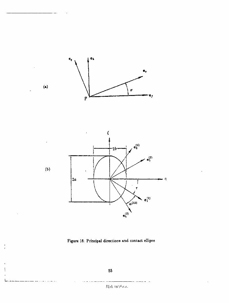
Bearing Contact
Theoretically,the pinionand geartoothsurfacesare in pointcontact.Under the load,
the contact is spread over an elliptical area. The determination of dimensions and orientation
24
of the instantaneouscontactrequires _;he knowledge of principal curvatures and directions
of the contacting surfaces. The solution to this problem is substantially simplified due to
representation of the curvatures of the generated surface by the curvatures of the generating
surfa_ and the parameters of motion [15].
For the case when the pinion generating surface is a cone, the principal cur a,tures of the
pinion generating sudac_ are r_prescnted as
kl'l = o (88)_l = cos<,,/(.:- s, sin<_.)
The principal directions on the pinion generating cone are
e_t) -- [-sinO, cosOp O]r (89)e(2l_ = [sinopcos8 v sinavsinOp -coso_] r
For the case when the pinion generating surface is a surface of revolution, the principal
curvatures of the pinion generating surface are represented as
_('_ = _f_' (90)k__l = cosX_t[Xo+ l_ .co_)
The principal directions on the pinion generating cone are
e('l = [-sinO, cos0. o]r (91)e_I) - [sin Al cos Ov sin A t sin Ov - cos .tt] r
Similarly, when the generating surface of the gear is also a cone, we have that the p_incipal
curvatures of the gear generating surface are
k__) ffi 0
k__ = cos_G/(r, - $_ sin a_)
The principal directions on the gear generating svgface are
(9.9.)
25
A[)A _lJ'Jf,;,¢,
i .,.,=
ep_ --- [-sln0o co,Oo O]re_2) = [sin aa cos Sa sin ac sizz 00
The pr/ncipal directions are represented in systems S_1
the gear c_Lse,respectively.
- _os _a]r (93)
for the pinion cas_, and S_ fc¢
Because the generating and generated surfaces are in line contact, their prirtcipsl ¢urva.
tares and directions are related by th.* following three equations [15]
2_l_t_q
k_q-k_ = kx+kh+ _"83
(94)
Here, k/, kh _re the principM curvgtures of tile generating surface; k,, k_ _re the principal
curvatures of the generated surface; a is the angle between the principal directions of the
generating and generated surfaces (fig. 18(a)). The expression for tts, f:s, and tm are
represented in [15_.
The determination of the dimensions of the contact ellipse and its orientation is based
on application of following equations
where
_an 2r = g_ sin am)gz - g2 cos a_ l_) (95)
e, = kI'_- kp_
= ')' .Pb
26
A[IA ,( ')_-,_,_.
k_'_ _.nd_ a_e the principal_t_ of the pinions_rf_e. _ _d k_2_
prindpal curvatures of the gear surface.
The m,_jor axis and minor axi; of the contact ellipse may be de_._mined as
are the
by
2.= 2V_2 , 2b=2_ (_6)
where 6 is the eb.st, ic approach obtained from experimental data; A and P. :re determined
and
7 Nunlerieal Examples
Introduction
The purpose of the numerical examples is: (i) to determine the influence of errors of
alignment on the transmission errors and the shift of the bearing contact, and (ii) to prove
that the predesigned parabolic function is able to absorb t,he tra,smissioa errors that ate
eau_d by the errors of alignment. We emphasize t,hat the determin_.tion of transmission
errors caused by misalign:nent is based on the following approach:
(1) We consid_ an imaginary process for generation when an ideal transmission func-
tion is provided. Then, using TCA, we simulate errors of alignment and determine the
transufission errors that are e._used by the respective error o( alignment.
27

r II ' I I
(2) On the t_ond stage of investigation, we consider again the imaginary method of
generation that has been provided in the previous section. We remind that tiffs method
of generation provides for e_:h cycle of meshing a transmission function and a prede,igned
parabolic function as the ,urn of the ideal linear function and a predesigned parabolic func-
tion. Using the TCA, we ¢onside_ the meshing axed ¢onta¢_ of toe jear misahgned gear drive
that allows to determine: (i) the resulting function of transmission errors as the sum of the
predesigned p_abo|ic function and the function of errors that is caused by rnisalignment.
We are also able to determine the shift of the bearing contact caused by rrfisMignrnent by
applying the TCA method.
The simulation of meshing and contact h_ been a_omplished for both methods of gen-
eration described above that provide the longitudinal bearing contact, and the across the
surface bearing contact. The results of computation confirmed that the bearing contact is
stable, and the predesigned parabolic function is able indeed to abaorb the almost linear
functions of transmission errors caused by the respective errors of alignment.
Input Data:
The input data is represent.ed in Tables 1-5.
Output Data:
The results of computation are represented for two on.sea of generation: (1) by application
of a pirdon head-cutter with straight blades (figs. 19-42); (ii) by application of a pinion
head-cutter with circular arc blades (figs. 48-66). It is assumed that in both cases the gear
is generated by a head-cutter with straight blades. In each case, four sets of figures represent
the respective influence of H, Q, V. $', which indicate the axial displac¢ment of the pinion,
the gear, the offset, and the change of the shaft angle, respectively. Alignment, errors are
given in millimeters,/_' is given ia arc minutes.
28
ADA ._t)'J%_,_.,

Table 1: Blank Data
umber of teeth-ShaftangleM_m, spiral ,angle '"Hand of spiral
"_)uter cone distance
Face width (ram) • ,j
Whole depth (ram)
PitchangleRoot angle
Face angle
Pinion Gear
11 41
90°
35° 35°
90.07
27.03
I0.0 I0.0
15°1 , 74*59'
15"1' 74*59'
1501 ' T4*59'
In each set of figures, we represent:
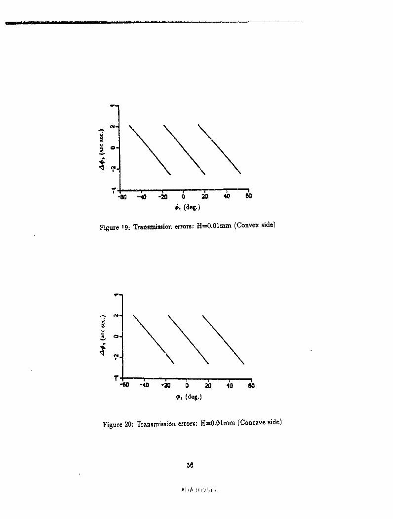
(i) The initial influence of mlsalignment on the transmission errors, when the prede_igned
parabolic function has not been applied. The tra.nsmission function caused by misaligameat
is almosta linearfunction(see, forinstance,figs.19 and 20).
(ii)The interactionof the linearfunctionof transmissionerrorswith the predesigned
p_rabolicfunction.The resultsof TCA show thattheobtainedresultingfunctionisindeed
a parabolic funct3on (see, for instance, figs. 21 and 23).
(iii) The loc_tion of bearing contact for a misxligned gear drive (see, for instance, figs,
23 and 24).
Similarsetsoffiguresererepresentedforotherkindsof misalignment.
29
ADA 30"P_(c,
IIiiii , ,,
Table 2: Gear Cutter Speci_cation
IBlade angle
t Cutt_ diameter (_)_,oi,_t._dth (ram) ,
Table 3: Gear Machine Tool Settings
_R_cliM sett:,_g (ram)-
Cradle angle
Machine center to back (ram)
Blank offsetrnm
Mac.Aine root angle"
_70.53744
-6201¥
0
o074"59'
Tab]e4: PinionMachine Too] Settingsfor Generationby a Cone
_utter blade' angle .....
Cutter pointradius ram)
_mmCradle angle
Cortvex
2o°?1.7222
68.049gi
-57°50 '
i_I_lilnecenter to back(ram) 0 •Slid . b=.(ram) oBlank oRrtet-(mm) .... __ 0
Machine _ootangle IYI'
Con_ve
20"
80.4876
73.31925
-66°IT
0
0
0• ,L, • ,,,
IYI'
3O
ADA3095:,g

Table _: Pinion Machine Tool Settings for Generation by tIead-Cutter with circular ArcBlades
Cutter point raAiius ram)
RaVel s_tting (ram)
Cr_lle _le
Mschine root angle
Convex Conca_,.'_
71.7222 80.4876
68.04991 73.3i925-57°50' -_°12'
0 0• r
0 0
'15Ol _ 1501 t -
8 Conclusion
Extension of application of a CNC machine for generation of spiral bevel gears with the fol-
lowing features has been discussed: (i) The gears are face-milled, the tooth depth is uniform.
(ii) Two types of bearing contact are provided directed (a) in the longitudinal direction, and
(b) in the d_r_tion across the surface. (iii) A predesigned parabolic function of transmission
errors is provided for the absorption of transmission errors c_used by rnisatignment. (iv)
Equations of generated pinion-gear tooth surfaces h,_ve been derived. (v) TCA computer
program has been developed and the influence of misalignment on the transmission errors
and the shift of the bearing contact h_s b_n investigsted. The computations that were
performed confirmed the stability of the bearing contact, the low level of transmission errors
and the favorable shape of _he function of transmission errors, of a parabolic type, for a
misaligned geax drive.
31

I I '"" it-
9 Directions for TCA Program Use
There are two TCA programs for two d_erent c._e_. One program is BEVEL.FOP_ for the
case tl_t both the pinion and the gear geneTating surfz.:es are cone surtaces. The other
program is RBEVEL.FOR, for the case that the pinion generating surface i_ _ surface of
revolution, the gear generating surface is a cone surface. For both pro_'an_ the input d,_t_
files and the output data files are almost the s_me, except th_.t there is an additional are
radius_ RHO, in the input data files for program RBEVEL.FOR.
Input data
1. Control codes
(a) I-br right hand gear JCH=I, for left hand gear JCH=2
(b) TL1 and TL2 are numbers of extra point on the contact path which should not be
larger that 2
(c) MM is the number of contact points
2. Blank d_ta
TN1--Pinion number of teeth
TN2--Gear number of teeth
C--ShaR offset (zero for spiral bevel gear) (mm)
TW--Face width of gear (ram)
GA_IMA--Shaft angle (degree)
32
MCD_M_ cone dist_ce (ram)
RGMAl--Pinion root ¢on_ angle (degree)
B1--Pinion spiral a_tgle (degree)
B2--Gear spiral angle (degree)
RGMA2--Gear root e.one angle (degree)
FGMA2---Ge_r face cone angle (degree)
PGMA2--Gear pitch cone angle (degree)
ADD2--Gear mean addendum (ram)
DED2--Gear mean dedendum (ram)
WD--Whole depth (ram)
CC---Clearance (ram)
DEL----Elastic appro_h (ram)
3. Gear cutter specification
RU2--Gear nominal cutter raztius (ram)
PW2--Poin: width of gear cutter (mm)
ALP2--1]lade angle of gear cutter (degree)
4, Gear machine-tool _ettings
XG2--Machine center to back (nun)
GAMA2--Ge_r machine root angle (degree)
XB2--$1iding bMe (nun)
33
[[I I I I II I I ,,,
EM2--Blank offset(ram)
4. Pinion machine-tool settings
RCF--Po_nt ra_us (ram)
XG1--M_hine center to back (ram)
XBl--Sliding base (ram)
EM1--BI_t_k offset (ram)
GAMAI--Pinion machine root angle (dega-ee)
AIP1--BIaAe _ngle of pinion cutter (degree)
6. Misaiignments
AmConstant coefficient of the predesigned parabolic function
H--Misalignment along the pinion axis (ram)
Q--Mitalignment along the gear axis (ram)
V--Misalignment of axis offset (ram)
6'--Misalignment o( shaftangle (_xcrain.)
Input data files
Files 70 and 60 are for program RBEVEL.FOR, file 70 for the convex side, file 60 for
*,he concave side. These two files must be read together. Files 90 and 80 are for program
BEVEL.FOR, file90 for the convexside,file80 forthe concaveside.These two files must
be read together.
Output data file,
34
File9 is an ove_a_ output data file. AU the input and output information is stored in thiJ
file. File 91 stores the information of transmission errors for the convex side; file 93 stores
the information of transmission errors for the concave side. File 92 stores the information of
contact path and contact eUipse for the convex side; _le 94 stores the information of contact
path and contact ellipse for the concave side.
35
ADA 3(J'v_.,_.,6
--. i r IIn I I I I I r ii, i
References
(1) Baxter, M.L. 1961. Basic geometry and tooth contact of hypoid gears. Indus. Math.
pp. 1-28
(2) Baxter, M.L. 1973. Second-Order Surface Generation. J. Industrial Mathematics, Vol
23, part 2, pp. 85-106
(3) Dongarrd,J.J.,Bunch, 3.R.,Moler,C.B.,and Steward,G.W. 1979. LINPACK User's
Guide, SIAM, Philadelphia
(4) Dudley, D.W. 1962. Gear Handbook, The Design, Manufacture, and Application of
Gears. McGraw-Hill, NY.
(5) Favard, J. Course of Local Differential Geometry, G_uthier-Vi|l_rs, Paris (in B-eneh:
translated into Russia.n)
(6) Goldrich, R.N. 1989. Theory of 6-axis generation of spiral bevel and hypoid gears.
AGMA paper 89FTM9
(7) Korn, G.A. and Korn, T.M 1968. Mathematics handbook for scientists and Engineers,
2nd ed., McGraw-Hill, NY.
(8) Litvin, F.L. 1960, 1968. Theory of Gearing, 1st ed. (1960), 2rid ed. (1968). Nauka (in
Russian)
(9) Litvin, F.L. 1969. Die Beziehungen Zwischen den KrSmmungeaa der Z_hnoberfliichen
bei Riumlichen Verzahnungen. Z. Angew. Math. Mech. 49:685-690 (in German)
(10) Litvin, F.L. and Gutrna_, Y. I. 1981. Methods of Synthesis for Hypoid Gear Drives of
Formate and Helixform, ASME J. Mechan. Design. Vol. 103, pp. 83-103
36
(11)Litvin,F.L.Pahn'_nP.andGoldrichR.N. !982, Mathematical Models for the Synthesis
and Optimization of Spiral Bevel Gear Tootk Surfaces, NASA CR-3553
(12) Litvin, F.L. and Zhang, Y. 1991(b). Local synthesis and tooth cxmtact analysis of
fec,_-rnJlled spiral bevel geaxs. NASA Contractor Report 4342, AVSCOM Technical
Report 90-C-028
(13) Litvin, F.L. and Hsiao, C.-L. 1993. Computerized simulation of meshing and contact
of enveloping gear tooth surfaces. J. Comp. Meth. Appl. Mech. Engrg. 102:337-336
(14) Litvin, F.L. 1989. Theory of Gearing, NASA Reference Publication 1212
(15) Litvin, F.L. 1994. Gear Geometry and Applied Theory, Prentice Hall
(16) More: Jorge J., G_rbow, Burton S., and Hilstorm, Kenneth E. 1980. User Guide for
MINPACK-I, Argonne National'Laborator_;Argonne, IL.
(17) Stadtfeld,I-I.J.1993. Handbook of Beve: and llypoidGears. RochesterInstituteof
Technology
(18)Stoker,J.J.1969.DifferentialGeometry, Willey-_nterscience
(19)Townsend, P.S.1991. Dudley'sGear Handbook, 2nd ed.:McGraw-Hill,NY
(20)Wildh_ber,E. 1946(c).Tooth Contact:Amer. Mach. 00:!I0-I14
(21_Wildhaber,E. 1956.SurfaceCurv0.tu:_.Prod. Engrg. 27:184-191
(22) ZMgaller, V.A. 1975. Theory of Envelopes, Nauk_, Moscow (in Russian)
37
At3A30'_5C_.,

(21 7
L_ Xm
Figure 1: Repre_mtation of axes of rotation of spiral bevel g_rs in coordinate system S,_
58
ADA ?,_j'v56c:,
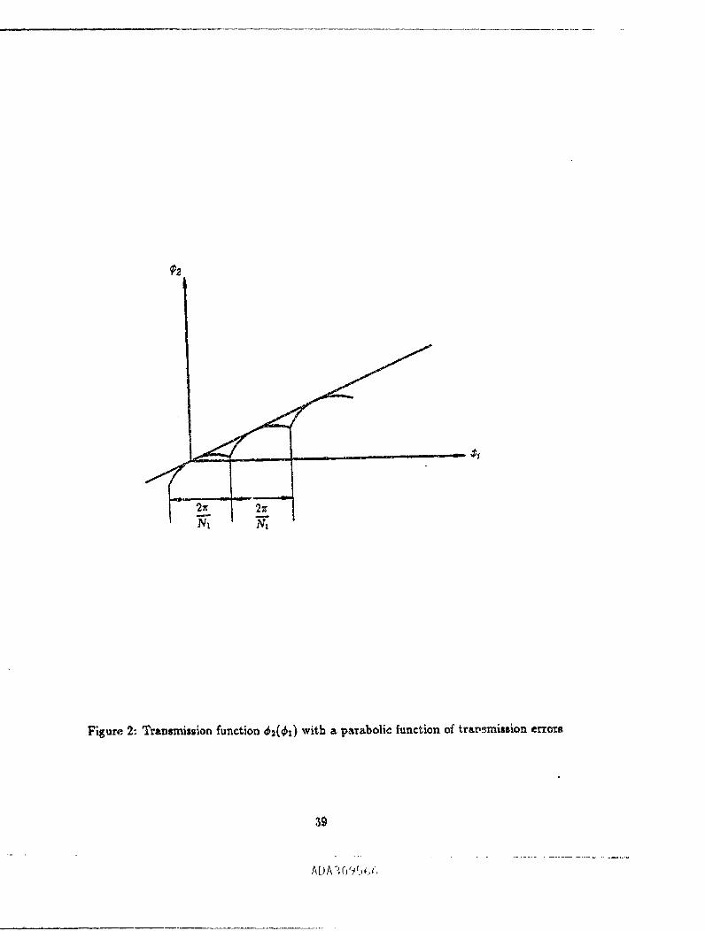
Figure 2: Trsnsmission function _2(_z) with a p_Tabolic function of trav_raission errors
A[)A_;O_5_,_,
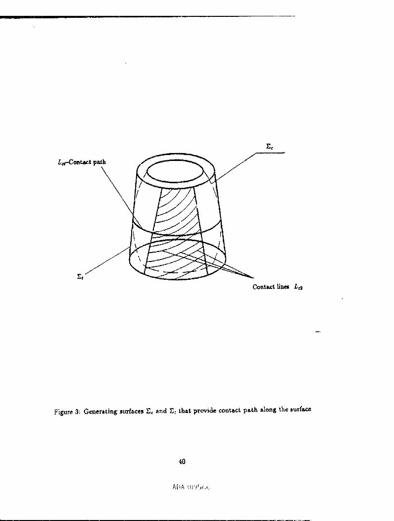
_C
L,_-Cont_t p_h
\
Et
Cont_t lin_ L_
Figure 3; G_mersting surhces E_ and _t that provide contact path along the surface
4O
A[)A :I ,_,t_,,,
!I
£s
Figure 4: Generating surfaces E_ and _ that provide a contact path across the surface
41
[ [ --
Blade
\
GeneratingCONES
Figure ,5: Ge_era_,ing blades and cones
42

(_)
Ycz Y_, Ydz
Xc2
0 '" -"- '"Ore, 0¢2 ,0 _ _ ,_ "Xm
Zd2 Zm, Zce
(h)
Urn, _'d8
Zd2_,
Figure6: Installmentand orientLtionofcoordinatesystemsS,_,S_2,Sd2,and $2
_3
A[_A3fJ'_t,' ,,
II r I i 'II iii'i i i r i -
(_)
Y. _C2
L_ _......._ Ruz
(6)
_2 Y_
Figure 7:Coordinate sys£erns S..,$e2,and Sp_ applied for gear generation
44
^[JA',rj'JS_><,

Xm XCZ
Am i
__. iLJ__I Xm
Figure 8: Machine-tool settings for geax generation
45
ADA ]095<,<,
[ FII I1= i
(*)
/
(b)
' \_Jl/
L ,"c _'F P W
Figure 9: Gear generating surface and its straight, line blade profiles
46
AI)A ,,l}'J%,,,,

V-Y.I
•_1 Xd!
Z!
(b)c,I
m
ZIp
47
I I q I I ' r r i ii n
"l0,40, _'1
(b)
OdJ 0 !
Z,
Figure 11: Coordinate syster_ S,,,, S_ z and Sn applied for pinion generation
48
AI._A:l;'_,_,_ -,
(a)
Y=
Zel
/9 "_ q_ =-
(b)
_'c I
O_ _ ql _',_ K.
FiguTe 12: For derivation of relation between imaginary and real pinion machine-tool set¢iags
49
L ! I I
_ _fConcave
z_ _ _Con vex
Figure t3: Profiles of pinion snd gear head-cutters represented in plane Z_ = 0
5O
r,p
,i
i
(a) For co_tcc_ve side
Figure 14: Proftesof straight-line pinion blades
51

i II 1 1 | I II i
Figure 15: For derivation of pinion generating cone eurft_ee
52
ADA .','._9%:,G

C_
J
Figure 16: Profi]es of pinion circuls.r-_r¢ blades
53
ADA _0'_,_,_,

V
O1Y_
Figure 17: Coordinate systems applied for simulation of n_hing
P
e_
(b)
2_
! /
_S "_
_. el'_
Figure 18: Prittciptl directions and contact ellips_
55
irl
N9
t_
X.,4- 7 .
| - _
'-60 -40 " 0 2O 4O
_, (dec.)
Figure 19: Transmission errors: H=O.Olmm (Convex side_
q_m
-6o ¸-¸J I I
"40 - 0 40
_,,(deg.)
Figure 20: Transmission errors: H=0.01mm (Concave side.)
56
/_i,A ;i_'Jc,t,r,
OII
m
<3" _.
-ira -40 -20. 0 20= 40 60
++,(deg.)
Figure 21: Reciting transmission errc_r,: H=O.Olmm (Convex side)
O_
t_
-CO| i + l I i | ii
-4O "_0 0 _ 4O
++,(++g.)
!
Figure 22: Reralting tr_smission errors: H=0.01mm (Concave side)
!
II
57
AI)A .',l)+.'+,c,+,

Tooth length (ram)
Figure 23: Shift ofbearing contact: H=0.01mm (Convex side)
Tooth length (ram)
Figure 24: Shift of bearing contact: Hf0.01n_ (Concave side}
58
A[)A ;_r)t,_,¢,
J
o,
q
Oa
d
?
jJJi
I I
_, (d_.)
Figure ,,5. Transrnis_on errors: Q=O.Olmm (Convex side)
_"' I I-,o -_ 6 6 ;o_ -"W
Figure 26: Transmission errors: q=0.01mm (Concave side)
59
A[,A 309_.,(/)

---[ __ I i
Q
"_ ?.,41.
mm4|
_e
M_
• _o= _
-e0 | i Iri _ l i II i-_ -so 2o 4o eO
_,(de_.)
Figure 27: P_uRing _ransmission e_rors: Q=0.01mm (Convex side)
QI
!
,p
?
N
!
ini i il i
l | | I I
-,to -2o 0 _ 4O
_', (deS.)
FiKure 28: Result, ing t,ransmlssion errors: Qs0.01mm (Concave side)
6O
.g
0 10 15 20 30
Tooth leugth (ram)
Figure 29: Shift of bearing contact: Q=O.Olmm (Convex side)
|nn I m ) #1 !# ',1 II I m0 S I0 15 _ 25 -_30
Tooth length (ram)
Figure30: Shiftofbearingcontact:Q=O,Olmm (Concave side)
61
AI_A30"/c",_,_,
_'i_zre 31: _ra_z_n_. ic _ errors: V_O.oln_ (Coz_ve_¢ S/de)
F_Sure _2. 7y_a_**ion e_o_a.. V_O.o1rn _ (Coocave side)
62
M
4
,a-60
L $ i
- -20 0 20
_ (_.)
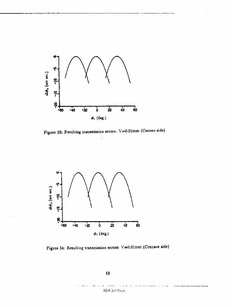
Figure33: P:_ulting_r_sn_ss[onerrors:V-O.O1mm (Convex side)
m
o
!
| _-- -- I ill II|IIIIIIII i I _ I | -- [
-60 -_tO -20 0 _0 'tO SO
_,(d_.)
Fisu_e34: F_u|ting t_ansmissi,on errors: V=O.O1mm (Concave sic_e)
63
ADA 3 )'__ _:,
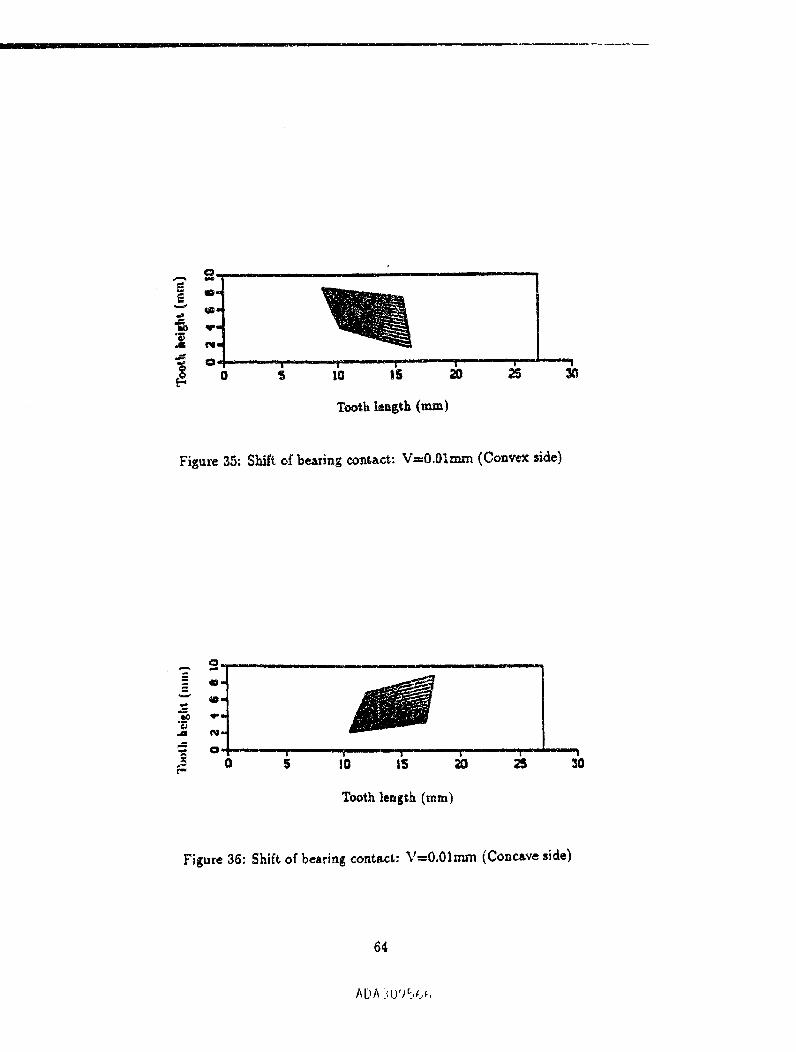
" iiI ..... | I I |
Tooth length (ram)
Figure 35: Shift of bearing contact: V-O.Olmm (Convex side)
0 ......... ,
J I"I "I II |
#
Tooth length (ram)
Figure 36: Shift of bearing contact.: V=O.01mm (Concave side)
64
Na
mml
4T-
!
Nl
-40 -20 O 6O
_1 (deg.)
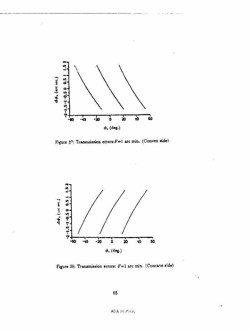
Figure 8_:Transl,fssioa errers:6'=l arc n'fin. (Convex side_
in
4a
T"b_
!
?I | il II| | | _0 I-_0 -20 0 2O
Figure 38: Transmission errors: 6'=I arc rain. (Concsve side)
6S
A[JA-',ll'_SI_,

]1 I1' I [ II ................. "
O'q
i !
-4O - 0 40
_ (des.)
Figure 30: Resulting transmission errors: _t--I arc min. (Convex side)
Oq
!
, ! |
*_ -tO. I, IIt
-;_ 0 20 _ 6O
_, (des.}
Figure 40: Resulting t_r_nsmission errors: 6'=1 arc rain. (Concave side)
66
M)A _,0'/%_ ,,
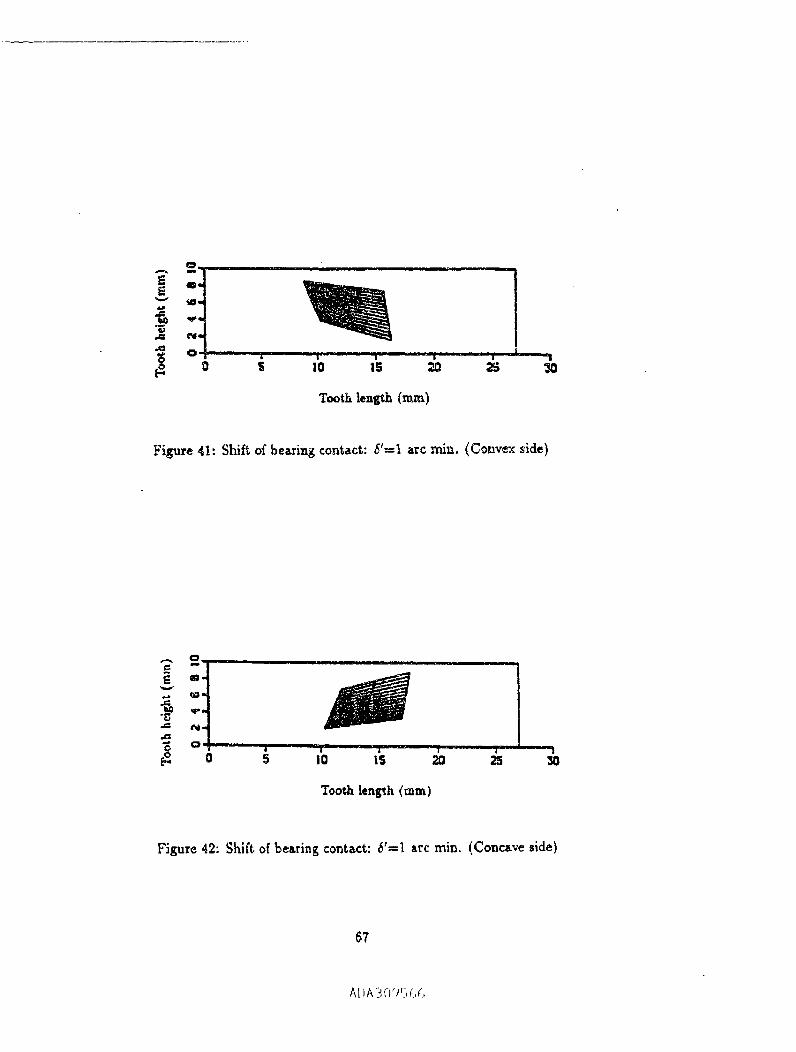
°'H I ........
_0
Tooth lenL_h (ram)
Figure 41: Shift of bearing contact: 6'---1 arc rain. (Convex side)
|0 5 I0 15 20 ;5 30
Tooth len_h (ram)
Figure 42: Shift. of bearing contact: 6'=1 arc rain. (Concave side)
67
AliA3-/_%(,¢,

....... i|
_oo.
o
I
o.om5 "' ' -- ' "'_1 _ ''-,to -20 4o 60
¢_,(deg.)
Figure 43: Transmission errors: H_0.01mm (Convex side)
To
X
o
o
I
o
o2!
-6O -40 _ 2O 4O 6O
_, (deg.)
Figure 44: Tr_nsrrdssion errors: H=0.01rnm (Concave side)
68
Al>A '; I'_'-J5 _i,_.,
OI
e
i1_, (deg.)
Figure 45: R-sultin_ transmission errors: H=0.01mm (Convex side)
_mI
"4C -20 0 20 40 5O
Figure 46: Re._ul_ing transmiaslon errors: H=0.01mm (Concave side)
69
Ai)A ¢l;_Jr,(,c,
III|" r
Tooth. len_;h {mln}
F_gu_ 47: Sh_ of bearing contact: H=0.01mm (Convex side)
i I.I rm |
0 $ I0 1.5 _ 25
Tooth length(ram)
Figure48: Shiftofbearingcontact:H--0.01mm (Concave side)
70
A[JA '_l}'{,_,_,

• mmm
-,_0 -29 0 20 ,_0 SO
_, (deg.)
Figuze 40: Tz_nsmJssion errors: Q=0.01mm (Convex side)
_a_t
u_
mma
o
fly+q'_" i___._il _ +-_ " /, ,
-60 -40 -20 0 20 40
_, (des.)
i!
SO
Figure 50: TraJ_sn_ssion errors: Q=0.01mm (Concave side)
71
A[,b, _,O'Ji,4,_i,
II rill ......
_a
t
Figu:e 51: Relating tra.ns_ssion errors: Q=O.Olrnm (Convex side)
OB
oms _'-
<l m
-60 -,_ -20 0 20. 40 60
¢1 (de_.)
Figure 52: P_ultin_ transnfiuion errors: Q--O.Olmm (Conczve side)
72
0 5 I0 15 20 25 '3G
TootlLlength (n_)
Figure 53: Shift o5 bearing contact: Q"0.01_ (Convex side)
_o
0 S I0 IS 2O .25
Toozh len_h (ram)
Fil;ure 54: Shift of bearin$ contact,: Q=O.Olnur, (Concave side)
73
AI _A;(}'Jr.-,_]c3

I I I
0..
?.
eq'_
?_ _o -_ "_ | I
40 BO
#, (d_.)
Figure 55: Transmissio_ errors:V=O.O1nn'n (Convex side)
"7.
fu
O-
T.
?I I : I -20 :-_o -_ o 4'o
¢, (d.g.)
Figure 56: Transmi.ion errors: V=0.01mm (Concave side)
74

-t'- , ' _ . . "l-60 -4O -20 0 21) 4O 60
Figure 57: Resultin_ transrrtis_on errors. V=O.O1mm (Conve_ side)
Oa
I
,_,, ._
_i, (dell,)
Figure 58: Resulting transmission errors: V=O.Olmm (Concave side)
A[JA ;f)<#_,_,_,
I II ,
0 S 10 IS 2.0 _ _0
Tooth len_,_ (ram)
Figure 59" Shift of besting contact: V_=O.Olmm (Convex side)
0 S tO IS 20 2S _0b
Tooth len_h (ram)
Fisure 60: Shift, of bearing contact: V_O.01rnm (Concsve side)
76
Nu
em,,i
_,. (aeg.)
Figure 61. Tr_nsrn_ion errors: 6'=I _r¢ min. (Convex side)
_m
m_
| I II i II • I |-- |
-(SO -40 -_0 0 _0 4OI I
SO
Figure 62: Trsusmission errors: _;'---I arc rain. (Concave side)
77
A[_A3095c,_.,

,n
_a
_a
e
i
-40 -20 0i,
2O 40 50
¢,, (deg.)
Figure 63: I_su|ting t_ansmission errors: _'=I arc rain. (Convex si_e)
';'"
'_ v,_.|
i_ !inJ _ mr il l I
-40 -20 0 20 4'0
¢,_ (deg.)
Figure 64: "__ulting transmission errors: _'-_l arc rain. (Concave side)
?8
A[IA ..,_I;9 _ e;r',
Tooth _a_h {m_n)
Figure 65: $hi_ of besting c_t_t: 6'---I _rc _n. (Convex side)
Tooth length (ram)
Figure 66: $]_ifc of _earmg contact: 6'--I arc rain. (Concave side)
79
ADAB09%/_(}
ir ilml i i iiiii iii
......... i ,. | i, , ,,m
IP FormApprove#REPORT DOCUMENTATION AGE I .... oue_.o?o_.o_u
Design andAnal_is of Face.Milled, Uniform Tooth I-I_gh_.
Low.Noise SpiralBeret Gear Drives WU-__
"- NAG3-.1607IL162211A47A
F.L. _ and X. 2]_o
NEPORT NUMBER
Universe-/of _ _t Chicago E-lOOg6Chicago, IlLinois 60680
U.$. A_y Reu_'chC_v_m_. O_ 44l_-3191 NASA CR-4704
A_-287NASA Lt_ds I_._cud_ Cm_
C1_e2s_s_ Oh/o 4,1135-_1191
11. _UPPMgiaEKrARY HOl'[I
P_roje__ag_, Rob_s'tF. HandsdmboVeb_;le Propulsion Di==ctorat¢. U.S. Army Re._e_rchLaboratory,NASA Lewis1EcseU_ Crater, o_ga_Eado_code2?30, (216) 433-3969.
":12_ I0_WAVAILABIi4rY liTA'IIGME_T ..... _i2b. _$1/uBt.rllotq COD'J_
Unclas_6_d -Ud/mited
SubjectCategory 37
Ti_ _mblimfion _t tvtiltble f_om the NASA Center for Arro_ infon_fiort, (30;) 621-0390.
A r,_wm_hod for _=s_tP_andgenerationof _iral l_vsl gearsof uniform ioo_ depthwiil_ l_alized b_wing C0nlaCta_dlow k_ve|of w_mm_r_on_ is considered.TI_ r_n featuresof ti_ p,'oposcdapprce:h _= as follows:(1) Thek3calizafi_ of the beanng ¢o,tt_ is schJove,d by the mismatch of the generating surfaces. The besting contactmay beprovided i_ Lhe]on_tudina] dir_on, or in the directi,=nacross the turface. (2) The low level of trentmission erroc; isa=b.ieveddue to appi_ of,onli_,_" relations between the motions o_ the gear and _ gear head-cutter. Such rd_onsmay be provided by appiicatio_ of a CNC m_hinc. _ gcncr_tic_ of the pinion is based on application of _ retationsbetw_n the modo_ of _ tool and the pinion being generated. Tr_ relations _tibe, d above pefmii a parabolic fut_ctionof eransmiss_n e_rors m _ obtained _ is able to absorb almost li,e_r functions _tused by etTors of ge_ Mig_ment. Acompeter a)d¢ has b_n written for the meshing and conutct of _e spinalbevel gears with _ proposed g¢omewy. Theeffectofmisal_gnrnenton_ prolx_mdgeometryhasalsob_n determined.Numeric_lexsmplesforillustrationoftl_
pmpoted theory have be_ provide&
Gem-,;t)ower enmlmission; Oar geometry
.... q ,i
17. lacU_rf'lf CIkAI_IMFIG&TION
OFI_IeORTUr_lassified
/1M0-01-280.GG00
• .,_,;-i,,x.,m=.,_ p_=82
,e. m=u¢,=(:_|A05
Und=_ified I,I ' ' _ '@u_).rd _on'_,_ (_.v, 2-al))
P_lo4d I_f M41BI III@,Z31).1_12(18-102
ADA309_,66