1998: ammonia process primary waste heat boiler shell .../fileser… · two vertical bayonet style,...
TRANSCRIPT
Ammonia Process Primary WasteHeat Boiler Shell Failure Experiences
Three cases of pressure shell failures during 20+years of operation are described. The results of thefailure analysis following each event are also presented, as well as a description of the repair meth-ods employed. Although the nature of the failures were not all similar, some common elements sur-
faced as a result of the failure investigations.
Colin P. JacksonCanadian Fertilizers Ltd., Medicine Hat, Alberta, Canada
Introduction
The Primary Waste Heat Boilers in an MWKellogg ammonia plant were first constructedto the subject design in the mid-1960s. It is esti-
mated that as many as 300 waste heat boilers of simi-lar design may be in operation around the world.Although generally reliable, the operating experienceover the ensuing 30 plus years has resulted in a num-ber of failures of varying types. Due to the nature ofthe process and materials involved, any incident hasthe potential for serious equipment damage and injuryto personnel. The information presented hi this paperis largely based on the operating experience of CFIndustries Inc. owned and managed facilities in theU.S. and Canada. For the most part, the material iscomprised of extracts from the failure investigationsconducted by others at the time of the related events.
Background
CF Industries Inc. (CFII) operates two 1,000 T/D
(900 tonnes/day) and two 1,150 T/D (1,025tonnes/day) ammonia trains in Donaldsonville, LA andtwo 1,150 T/D (1,025 tonnes/day) units at theCanadian Fertilizers Limited (CFL) site in MedicineHat, Alberta, Canada. All of these units have beensubstantially debottlenecked in several stages to cur-rent capacities, approximately 140% of originaldesign. The primary waste heat boilers were notchanged as a part of the debottlenecking projects.
The MW Kellogg Steam / Methane reforming opera-tion and its attendant waste heat recovery boilers arethe first processing stage in the preparation of a hydro-gen rich synthesis gas for the production of anhydrousammonia.
Hydrogen is typically produced from natural gas andsteam through the reforming reaction in two stages. Atubular fired primary reforming furnace is followed bya secondary reforming reactor vessel. Ah", injected atthe inlet of the secondary reformer, consumes a por-tion of the primary reformer product to produce theheat required to reform the balance of the methane to aresidual level of about 0.2%. The reformed gas exits
AMMONIA TECHNICAL MANUAL 69 1999
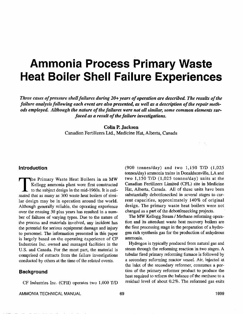
the secondary reformer at approximately 1,800°F(982°C) and passes through parallel transfer lines totwo vertical bayonet style, waste heat boilers. (FigureD
These boilers produce 1,500 psig (10,300 KPa)steam and are a major source of power for the steamturbine driven compression equipment required forprocess operation. The primary components of theprocess gas stream at this point are hydrogen, nitro-gen, carbon dioxide, carbon monoxide and steam.
Waste Heat Boiler Design
The extreme temperatures and high reactivity of thehot reformed gas stream requires some special consid-eration of design and materials for reliable operation.Figure 2 illustrates the construction of the pressurecontaining the shell of the boiler and it's design fea-tures to compensate for the extreme operating condi-tions presented by the process.
The pressure shell is constructed of carbon steelplate (SA 516- Gr. 70) and has additional thickness inthe upper and lower portions to provide the necessary
S«i»lny MonMt
Boiler Feed WaterI5»PSI»SMF(SISC)
Boiler Feed Watertsoopsi e SOOF piscj
reinforcement for the inlet and outlet nozzles. Thepressure shell is enclosed in an atmospheric pressurewater jacket which was originally provided with levelcontrols and operates with a supply of steam conden-sate as the cooling medium.
The inside of the vessel shell is lined with 5 in (13cm) of bubbled alumina refractory. The refractory isshielded from the erosive action of the flowing processgas by stainless steel shrouding. The nozzles are con-structed hi similar fashion.
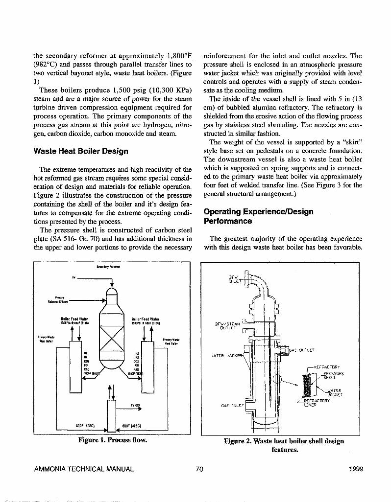
The weight of the vessel is supported by a "skirt"style base set on pedestals on a concrete foundation.The downstream vessel is also a waste heat boilerwhich is supported on spring supports and is connect-ed to the primary waste heat boiler via approximatelyfour feet of welded transfer line. (See Figure 3 for thegeneral structural arrangement.)
Operating Experience/DesignPerformance
The greatest majority of the operating experiencewith this design waste heat boiler has been favorable.
\ WATERTACKET
fi Aï INLEr
Figure 1. Process flow. Figure 2. Waste heat boiler shell designfeatures.
AMMONIA TECHNICAL MANUAL 70 1999
T0 MIS
REFORMEDGAS IN
ITEM. 101-CA ITEM: 101-CB
Figure 3. General arrangement of vesselattachments and supports.
Operators recognized early in the life of the plantdesign that the integrity of the shell temperature pro-tection was critical to the safe operation of the plant.The general reliability of the design is supported bythe finding that the majority of operators have hadonly minor shell failures or none at all.
Early operating experience indicated the water jack-et level control system was in need of improvement asthe turbulence due to boiling in the jacket was suffi-cient to produce repeated activation of the jacket waterlevel alarms. A number of solutions have been imple-mented. At the CFL facility the level control wasreplaced with a flow control and the jackets are oper-ated with an overflow of approximately 60 gpm (2301pm) shell. The low level alarm remains in operationas further verification that water remains in the jack-ets.
Annual scheduled plant maintenance turnaroundswere the rule through the mid 1980s. The shell insula-tion of the waste heat boilers together with their inletand outlet lines was a priority for inspection duringeach opportunity. Most often these inspectionsrevealed some distortion of the internal shroud materi-
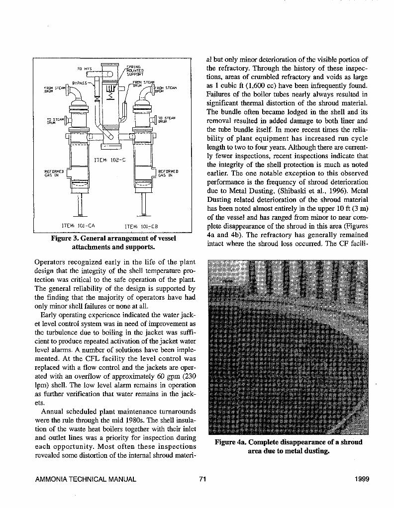
al but only minor deterioration of the visible portion ofthe refractory. Through the history of these inspec-tions, areas of crumbled refractory and voids as largeas 1 cubic ft (1,600 cc) have been infrequently found.Failures of the boiler tubes nearly always resulted insignificant thermal distortion of the shroud material.The bundle often became lodged in the shell and itsremoval resulted in added damage to both liner andthe tube bundle itself. In more recent times the relia-bility of plant equipment has increased run cyclelength to two to four years. Although there are current-ly fewer inspections, recent inspections indicate thatthe integrity of the shell protection is much as notedearlier. The one notable exception to this observedperformance is the frequency of shroud deteriorationdue to Metal Dusting, (Shibaski et al., 1996). MetalDusting related deterioration of the shroud materialhas been noted almost entirely in the upper 10 ft (3 m)of the vessel and has ranged from minor to near com-plete disappearance of the shroud in this area (Figures4a and 4b). The refractory has generally remainedintact where the shroud loss occurred. The CF facili-
Figure 4a. Complete disappearance of a shroudarea due to metal dusting.
AMMONIA TECHNICAL MANUAL 71 1999
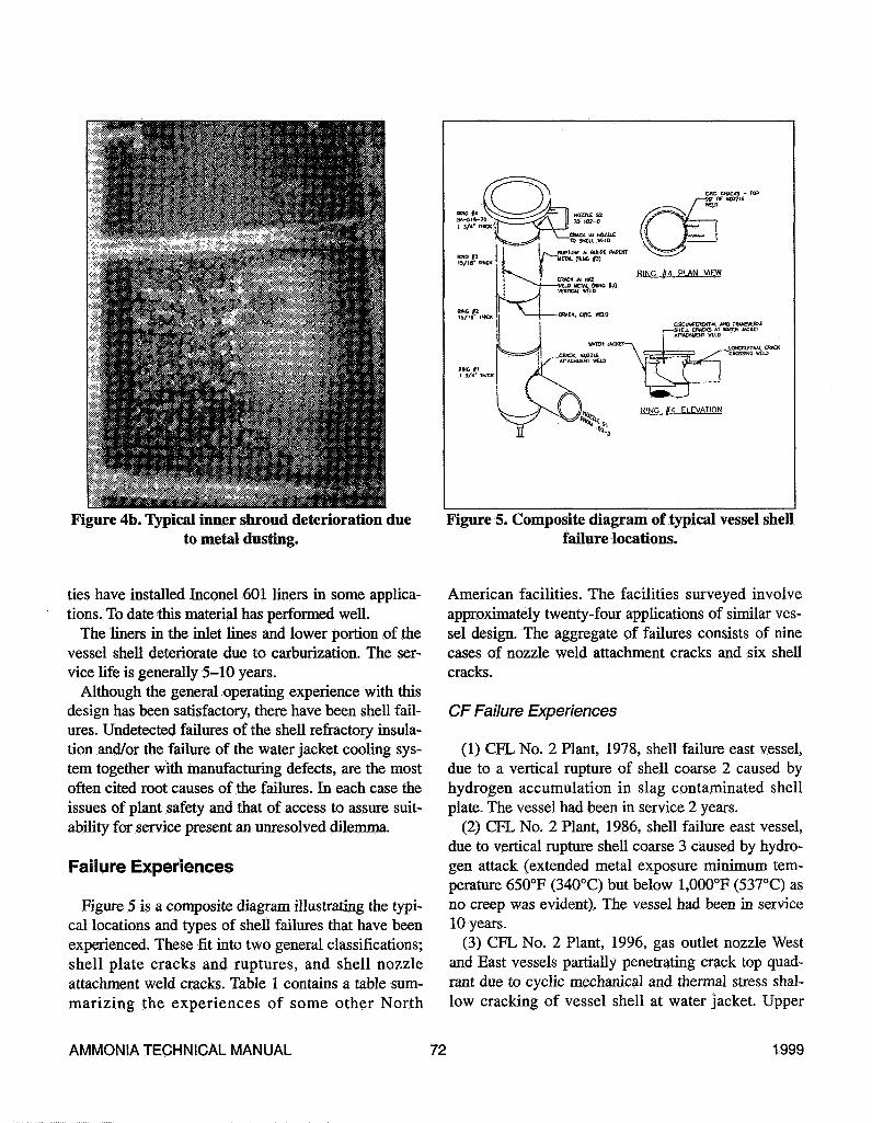
Figure 4b. Typical inner shroud deterioration dueto metal dusting.
RUPtdftC k BULGE PAStKT
•WE J> HOM. (RING |3)
Ofic CHECKS - ra?OF NOZZLE
HEU)
RING PLAN ViEW
CHCUUFEROfllM. AHO TtUN£VDlS£, SHt'JL CRflCXS At «Mtft JACKH
WCID
WATER JACKET—
#4 ELEVATION
Figure 5. Composite diagram of typical vessel shellfailure locations.
ties have installed Inconel 601 liners in some applica-tions. To date this material has performed well.
The liners in the inlet lines and lower portion of thevessel shell deteriorate due to carburization. The ser-vice life is generally 5-10 years.
Although the general operating experience with thisdesign has been satisfactory, there have been shell fail-ures. Undetected failures of the shell refractory insula-tion and/or the failure of the water jacket cooling sys-tem together with manufacturing defects, are the mostoften cited root causes of the failures. In each case theissues of plant safety and that of access to assure suit-ability for service present an unresolved dilemma.
Failure Experiences
Figure 5 is a composite diagram illustrating the typi-cal locations and types of shell failures that have beenexperienced. These fit into two general classifications;shell plate cracks and ruptures, and shell nozzleattachment weld cracks. Table 1 contains a table sum-marizing the experiences of some other North
American facilities. The facilities surveyed involveapproximately twenty-four applications of similar ves-sel design. The aggregate of failures consists of ninecases of nozzle weld attachment cracks and six shellcracks.
CF Failure Experiences
(1) CFL No. 2 Plant, 1978, shell failure east vessel,due to a vertical rupture of shell coarse 2 caused byhydrogen accumulation in slag contaminated shellplate. The vessel had been in service 2 years.
(2) CFL No. 2 Plant, 1986, shell failure east vessel,due to vertical rupture shell coarse 3 caused by hydro-gen attack (extended metal exposure minimum tem-perature 650°F (340°C) but below 1,000°F (537°C) asno creep was evident). The vessel had been in service10 years.
(3) CFL No. 2 Plant, 1996, gas outlet nozzle Westand East vessels partially penetrating crack top quad-rant due to cyclic mechanical and thermal stress shal-low cracking of vessel shell at water jacket. Upper
AMMONIA TECHNICAL MANUAL 72 1999

Table 1. Industry Survey of Waste Heat Boiler Shell Failure Experience
FacUity Material of
Construction
1
2 SA 212 gr. B
3 N/A4 SA 5 16-70
4
4 SA 5 16-70
4
5
Failure Type
Cracks
Bulge, Crack
NoneTransverse cracks
Circumferential anctransverse cracks,partial and full
penetration.Circumferential anctransverse cracks;Partial penetration.No Shell Failures,
Inspected byremoving the lining
atlastT/AnoWeld crack
Location
Both nozzles allaround
15/16 in(2.3 cm]Shell section
_
S2 nozzle weld
Upper flangeattachment weld/joint to jacket,support ring
Upper flangeattachment weld/
ioint to jacket
Outlet nozzle
Cause
Operations upset.Overheat. Slag in plateand weld defects
Loss of refractorysuspected
Thermal fatigue due to thefluctuating water level in
the jacketThermal fatigue due to thefluctuating water level in-
the jacket.
Thermal fatigue due to thefluctuating water level in
the jacket.
Original assembly; StressInduced
Age at
Time of
Failure
11 yr.
5 yrs
15 yrs
15 yrs
15 yrs
15 yrs
Plant
Capacity
1,150
1000
1,150
1,150
1,000
Year
Built
76
66
75.7777
77
77
68
AMMONIA TECHNICAL MANUAL 73 1999

attachment weld due to thermal cyclic stress. The ves-sels had been in service 20 years.
(4) CPU No. 1 Plant, 1978, gas outlet nozzle southvessel, a full penetrating crack and several shallowcracks in the nozzle attachment weld. Thermal ormechanical stress was the probable cause. The vesselhad been in service 11 years.
(5) CFII No. 1 Plant, 1986, gas outlet nozzle southvessel, full penetration crack initiating near top of pipeat vessel weld, caused by lack of a post weld heattreatment of a prior repair in an area of cyclic stress.Shallow cracking in adjacent vessel wall. The vesselhad been in service 20 years.
(6) CPU No. 1 Plant, 1986, outlet gas nozzle northvessel, shallow cracks in vessel wall near top of noz-zle; probable cause was cyclic stress as above. Thevessel had been hi service 20 years.
(7) CPU No. 4 Plant, 1995, inlet nozzle attachmentweld failure south vessel, partially penetrating circum-ferential cracks to the mid wall area in the attachmentweld of the inlet nozzle. Cause was attributed to ashroud failure, refractory loss and manufacturingdefects in the original weld. The vessel had been inservice 19 years.
(8) CFH No. 3 Plant, 1997, shell failure south vesseldue to vertical rupture in shell coarse 3, caused bycreep due to extended exposure in the temperaturerange 900-1150°F (480-621°C). No evidence ofhydrogen attack.
• Gas outlet nozzle partial through crack due tocyclic mechanical and/or thermal stress.
• The vessel had been in service 21 years.
Case Histories
Case 1: Canadian Fertilizers Ltd, November1986.
The Incident. At approximately 10:45 p.m. onNovember 13, 1986, the pressure shell of the eastPrimary Waste Heat Boiler in the No. 2 AmmoniaPlant failed, shutting down plant operation. Operatorson shift at the time reported hearing a series of threeloud explosion like sounds and observed a large cloudof fire and steam to the south and east of the east pri-mary waste heat boiler location. A loud roar was also
Figure 6a. Elevation looking west at rapture site,extensive insulation & minor piping damage
(Wagner, 1986).
noted following the explosions. The feed and fuel gaswere immediately isolated from the plant and the nor-mal process vents were opened to depressure the plantvia the vent stacks.
An initial inspection, following the depressurizationof the plant, revealed a large amount of insulation hadbeen stripped from the piping in the area and all nor-mal access ways were littered with debris. More com-prehensive inspection was delayed until the followingmorning as the area lighting was out of service.
In addition to the shell damage, an electrical conduittray was severely damaged by the resulting fire. Therewas minor piping and instrumentation damage, and alarge area where the pipe insulation was stripped fromthe lines. (Figures 6a and 6b.)
The failure occurred hi the parent metal of the upper15/16 in. (2.4 cm) thick section of the pressure shell(ring 3) and was recognized as a vertical thick lip rup-ture approximately 30 in. (76 cm) long with a 3 1/4 in.(8.25 cm) opening at the widest point. The rupturedmaterial protruded outward approximately 4 in. (10cm). One end of the split extended to the circumferen-tial weld joining the two 15/16 in. (2.4 cm) coursesand although there was a crack in the circumferentialweld, the ruptured split did not link up with the cir-cumferential weld crack (Figures 7a, 7b, and 7c)
AMMONIA TECHNICAL MANUAL 74 1999

Figure 6b. Plan view - east of rapture location,damaged electrical conduit and pipe insulation
(CFL, 1986).
(Radian, 1987).The Cause. Samples of the failed vessel shell mater-
ial were sent to Radian Corporation (now Mechanicaland Materials Engineering) for failure analysis.
The shell section showed a severe bulge in the rup-ture area which initially indicated the shell had beenlocally overheated. The area surrounding the ruptureshowed signs of secondary cracking which indicatedthe possibility of hydrogen damage. An examinationwas done using straight beam ultrasonic which indi-cated the damage was localized to the area surround-ing the rupture.
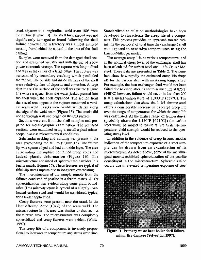
Figure 8 shows a polished and etched photomicro-graph of the secondary cracking near the rupture lip.The cracking is intergranular in nature and most of thepearlite is missing from the microstructure as a resultof decarburization. The higher magnification photomi-crographs shown in Figure 9 show the microstructureof the shell at the rupture and the intergranular crack-ing is associated with the pearlite breakdown.
Microcracking and the breakdown of pearlite bydecarburization is the classic manifestation of hightemperature hydrogen attack. The microcracking iscaused when hydrogen diffuses into the steel at tem-peratures above 440°F (225°C). The hydrogen reactswith the carbon present in solid solution or in the formof iron carbide to form methane. The methane accu-
Figure 7a. Bulged shell section, ring 3(CFL, 1986).
Figure 7b. Rapture damaged shellsection (CFL, 1986) 30 in. long x 3 1/4 in.
wide x 4 in. (82 cm x 8cm x 10 cm)protrusion.
AMMONIA TECHNICAL MANUAL 75 1999
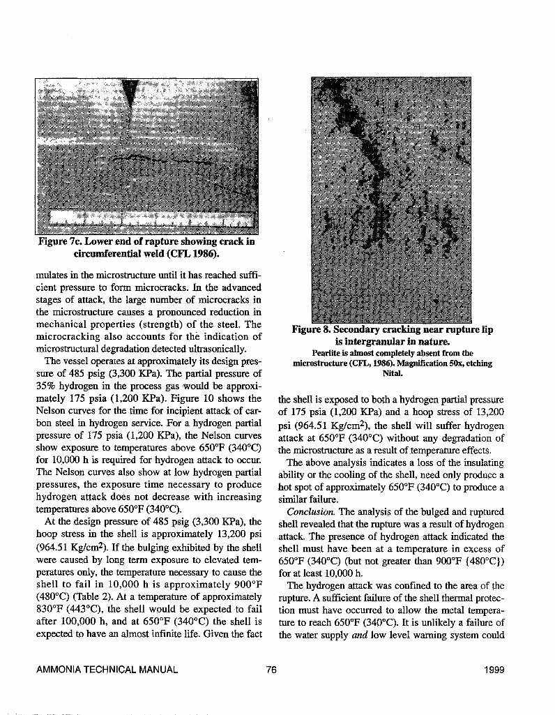
Figure 7c. Lower end of rapture showing crack incircumferential weld (CFL1986).
mulates in the microstructure until it has reached suffi-cient pressure to form microcracks. In the advancedstages of attack, the large number of microcracks inthe microstructure causes a pronounced reduction inmechanical properties (strength) of the steel. Themicrocracking also accounts for the indication ofmicrostructural degradation detected ultrasonically.
The vessel operates at approximately its design pres-sure of 485 psig (3,300 KPa). The partial pressure of35% hydrogen in the process gas would be approxi-mately 175 psia (1,200 KPa). Figure 10 shows theNelson curves for the tune for incipient attack of car-bon steel in hydrogen service. For a hydrogen partialpressure of 175 psia (1,200 KPa), the Nelson curvesshow exposure to temperatures above 650°F (340°C)for 10,000 h is required for hydrogen attack to occur.The Nelson curves also show at low hydrogen partialpressures, the exposure time necessary to producehydrogen attack does not decrease with increasingtemperatures above 650°F (340°C).
At the design pressure of 485 psig (3,300 KPa), thehoop stress in the shell is approximately 13,200 psi(964.51 Kg/cm2). If the bulging exhibited by the shellwere caused by long term exposure to elevated tem-peratures only, the temperature necessary to cause theshell to fail in 10,000 h is approximately 900°F(480°C) (Table 2). At a temperature of approximately830°F (443°C), the shell would be expected to failafter 100,000 h, and at 650°F (340°C) the shell isexpected to have an almost infinite life. Given the fact
Figure 8. Secondary cracking near rupture lipis intergranular in nature.
Pearlite is almost completely absent from themicrostructure (CFL, 1986). Magnification 50x, etching
Nital.
the shell is exposed to both a hydrogen partial pressureof 175 psia (1,200 KPa) and a hoop stress of 13,200psi (964.51 Kg/cm2), the shell will suffer hydrogenattack at 650°F (340°C) without any degradation ofthe microstructure as a result of temperature effects.
The above analysis indicates a loss of the insulatingability or the cooling of the shell, need only produce ahot spot of approximately 650°F (340°C) to produce asimilar failure.
Conclusion. The analysis of the bulged and rupturedshell revealed that the rupture was a result of hydrogenattack. The presence of hydrogen attack indicated theshell must have been at a temperature in excess of650°F (340°C) (but not greater than 900°F {480°C})for at least 10,000 h.
The hydrogen attack was confined to the area of therupture. A sufficient failure of the shell thermal protec-tion must have occurred to allow the metal tempera-ture to reach 650°F (340°C). It is unlikely a failure ofthe water supply and low level warning system could
AMMONIA TECHNICAL MANUAL 76 1999
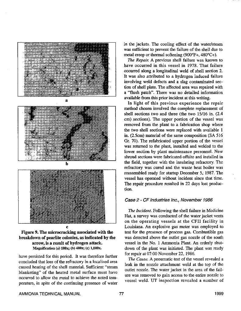
Figure 9. The microcracking associated with thebreakdown of pearlite colonies, as indicated by the
arrow, is a result of hydrogen attack.Magnification (a) lOOx; (b) 400x; (c) l.OOOx.
have persisted for this period. It was therefore furtherconcluded that loss of the refractory in a localized areacaused heating of the shell material. Sufficient "steamblanketing" of the heated metal surface must haveoccurred to allow the metal to achieve the noted tem-perature, in spite of the continuing presence of water
in the jackets. The cooling effect of the water/steamwas sufficient to prevent the failure of the shell due tometal creep or thermal softening (900°F+, 480°C+).
The Repair. A previous shell failure was known tohave occurred in this vessel in 1978. That failureoccurred along a longitudinal weld of shell section 2.It was also attributed to a hydrogen induced failureinvolving weld defects and a slag contaminated sec-tion of shell plate. The affected area was repaired witha "flush patch". There was no detailed informationavailable from this prior incident at this writing.
In light of this previous experience the repairmethod chosen involved the complete replacement ofshell sections two and three (the two 15/16 in. (2.4cm) sections). The upper portion of the vessel wasremoved from the plant to a fabrication shop wherethe two shell sections were replaced with available 1in. (2.5cm) material of the same composition (SA 516Gr. 70). The refabricated upper portion of the vesselwas returned to the plant, installed and welded to thelower section by plant maintenance personnel. Newshroud sections were fabricated offsite and installed inthe field, together with the insulating refractory. Therefractory was cured and the waste heat boiler wasreassembled ready for startup December 5, 1987. Thevessel has operated without incident since that time.The repair procedure resulted in 22 days lost produc-tion.
Case 2 - CF Industries Inc., November 1986
The Incident. Following the shell failure in MedicineHat, a survey was conducted of the water jacket ventson the operating vessels at the CFII facility inLouisiana. An explosive gas meter was employed totest for the presence of process gas. Combustible gaswas detected above the outlet gas nozzle of the southvessel in the No. 1 Ammonia Plant. An orderly shut-down of the plant was initiated. The plant was readyfor repair at 07:00 November 22, 1986.
The Cause. A pneumatic test of the vessel revealed aleak in the nozzle attachment weld at the top of theoutlet nozzle. The water jacket in the area of the fail-ure was removed to gain access to the entire nozzle tovessel weld. UT inspection revealed a number of
AMMONIA TECHNICAL MANUAL 77 1999

cracks in the upper quadrant (90°) of the nozzle cir-cumference that extended longitudinally into the par-ent material of the nozzle. Some small cracks werealso detected which extended across the weld into thevessel shell material. Two shallow cracks were identi-fied in a similar location in the vessel wall of the adja-cent north positioned boiler shell. The nozzle materialof construction was A357 (5 Cr. 0.5 Mo.). These ves-sels had a history of cracking in the upper portion ofthe nozzle weld area approximately 8 years previously.As there was no record of post weld heat treatmentfollowing the previous repair, it was concluded thiswas a factor contributing to the recurrent cracking inthe area of mechanical and thermal cyclic stress.
The Repair. The repair procedure was developed inconjunction with a consulting metallurgist and theHarford Insurance, Authorized Inspector responsiblefor this facility. The original material of constructionwas no longer available; it has been replaced by A387.The chosen repair method involved removal of thedamaged upper portion of the nozzle and replacementwith a section of the A387 material which was pre-pared to fit. All cutting and welding operations werepreceded by a "hydrogen bake out". The repair areawas preheated to 350°F (177°C) prior to welding andpost weld heat treated following the completion ofwelding.
The cracks, which extended into the vessel wall,were removed by grinding and repaired by welding
Figure 10. Nelson curve for temperature effect on timefor hydrogen attack of carbon steel (réf. 1 Radian,
Report 1987).
with Inco A filler material. The plant was restarted fol-lowing the repair, with approximately 5 days lost pro-duction.
Case 3 - CF Industries Inc. Dec. 1997
The Incident. On December 1, 1997, the pressureshell of the south waste heat boiler in No. 3 AmmoniaPlant failed, resulting in a fire in addition to the dam-age to the boiler shell. The plant appeared to be oper-ating normally and had started up normally after bothan extensive September turnaround and a shortOctober outage. The tube bundle had been replaced onthe September turnaround. During the September turn-around, a routine inspection found no damage to theinternal liner and hence no reason to suspect anyrefractory failure in this area.
On November 30, 1997, the routine explosive test ofthe water jacket was negative. On the evening ofDecember 1, the routine explosive test indicated posi-tive. The field operator was called away to anotherlocation in the plant just after completing the explo-sive test. A few minutes later, Operations personnelheard a loud blowing noise in the plant. When the con-trol room door was opened to investigate, fire wasobserved coming from the gap at the top of the southwaste heat boiler water jacket overflow trough. TheOperations personnel immediately took the natural gasout of the front end of the plant and shut the unit
down. The fire extinguished as the gas was takenout of the plant. The fire had been hot enough tomelt the aluminum covering of nearby insulation.However, there was no significant damage to sur-rounding facilities (Figure 11).
The Cause. Samples were removed from thefailure areas (2) and from an area of the sameshell section remote from the failure locations andsent for metallurgical analysis to ScientificTesting Laboratories and to Radian International(now Mechanical & Materials Engineering)(Pagendarm et al, 1998).
The damaged shell section contained two fail-ures: a bulged area with a vertical ruptureapproximately 8 in. (20 cm) in length with anopening of 1/2 in. (1.3 cm) (Figures 12a and 12b)and a 5 in. (15 cm) long partially penetrating
AMMONIA TECHNICAL MANUAL 78 1999
crack adjacent to a longitudinal weld seam 180° fromthe rupture (Figure 13). The shell liner shroud was notsignificantly damaged as found following the shellfailure however the refractory was almost entirelymissing from behind the shroud in the area of the shelldamage.
Samples were removed from the damaged shell sec-tion and examined visually and with the aid of a lowpower stereomicroscope. The rupture was longitudinaland was in the center of a large bulge. The rupture wassurrounded by secondary cracking which paralleledthe failure. The outside and inside surfaces of the shellwere relatively free of deposits and corrosion. A largedent in the OD surface of the shell was visible (Figure14) where a spacer from the water jacket pressed intothe shell when the shell expanded. The section fromthe vessel area opposite the rupture contained a verti-cal seam weld. Cracks were visible which ran alongthe edge of the weld seam (Figure 13). The cracks didnot go through wall and began on the OD surface.
Sections were cut from the shell samples and pre-pared for metallographic examination. The preparedsections were examined using a metallurgical micro-scope to assess microstructural conditions.
Substantial necking and thinning was present hi thearea surrounding the failure (Figure 15). The failurelip was square edged and had an oxide layer. The areasurrounding the rupture contained creep voids andlacked plastic deformation (Figure 16). Themicrostructure consisted of spheroidized carbides in aferrite matrix (Figure 17). These features are typical ofthick-lip stress rapture due to long term overheating.
The microstructure of the sample remote from thefailures consisted of pearlite hi a ferrite matrix. Slightspheroidization was evident along some grain bound-aries. This microstructure is typical of a slightly over-heated carbon steel and would be considered typicalfor a boiler application.
Creep fissures were present near the crack in theHeat Affected Zone (HAZ) of the seam weld. Themicrostructure hi this area was similar to that seen atthe rupture area. The microstructure was completelyspheroidized and creep fissures were evident (White,1997).
The creep life of a component is inversely propor-tional to increases in temperature and stress over tune.
Standardized calculation methodologies have beendeveloped to characterize the creep life of a compo-nent. This process provides an approach toward esti-mating the period(s) of total time the (exchanger) shellwas exposed to excessive temperatures using theLarson-Miller parameter.
The average creep life at various temperatures, andat the nominal stress level of the exchanger shell hasbeen calculated for carbon steel and 1 1/4 Cr. 1/2 Mo.steel. These data are presented in Table 2. The num-bers show how rapidly the estimated creep life dropsoff for the carbon steel with increasing temperature.For example, the heat exchanger shell would not havefailed due to creep after its entire service life at 825°F(440°C) however, failure would occur in less than 200h at a metal temperature of 1,000°F (537°C). Thecreep calculations also show the 1 1/4 chrome steeloffers a considerable increase in expected creep lifeover the range of temperatures for which the creep lifewas calculated. At the higher range of temperatures,(probably above the 1,150°F {621°C}) the carbonsteel would be subject to tensile failure as its, at-tem-perature, yield strength would be reduced to the oper-ating stress level.
In addition to the evidence of creep fissures anotherindication of the temperature exposure of a steel sam-ple can be drawn from an examination of itsmicrostructure. As noted above, some of the metallur-gical mounts exhibited spheroidization of the pearliteconstituent in the microstructure. Spheroidizationoccurs due to elevated temperature exposure of steel
Figure 11. Primary waste heat boiler shell failureminor fire damage (Yelverton, 1997).
AMMONIA TECHNICAL MANUAL 79 1999

Figure 12a. Shell "bulge" in failure area(Yelverton, 1997).
Figure 13. Cracks adjacent to weld seam remotefrom the leak site (Yelverton, 1997).
Figure lib. Bulged shell area and crack(Yelverton, 1997).
Figure 14. Shell dent on OD of bulged surface(Yelverton, 1997).
AMMONIA TECHNICAL MANUAL 80 1999
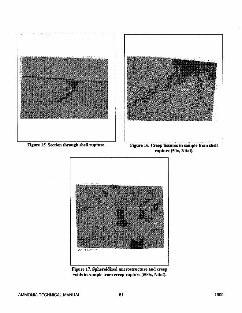
Figure 15. Section through shell rupture. Figure 16. Creep fissures in sample from shellrupture (50x, Nital).
Figure 17. Spheroidized microstructure and creepvoids in sample from creep rupture (500x, Nital).
AMMONIA TECHNICAL MANUAL 81 1999
over time. Spheroidization can typically occur aboveabout 800°F (426°C). The pearlite (or iron carbide)phase in the steel changes shape from a plate-type oran unresolved form into a spherical shape. Thischange is proportional to the temperature and the timeat temperature. Above about 1350°F (730°C) the steelis said to transform or re-crystallize. This microstruc-tural change is usually evident and was not observedin the metallurgical samples examined.
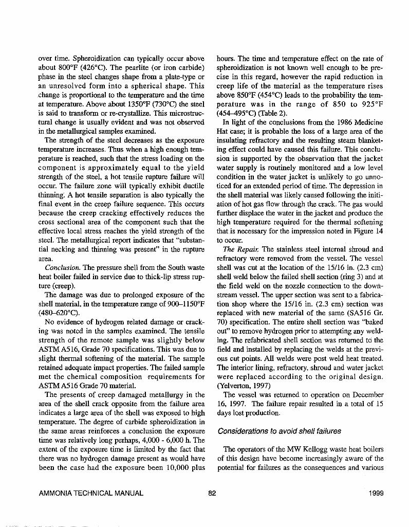
The strength of the steel decreases as the exposuretemperature increases. Thus when a high enough tem-perature is reached, such that the stress loading on thecomponent is approximately equal to the yieldstrength of the steel, a hot tensile rupture failure willoccur. The failure zone will typically exhibit ductilethinning. A hot tensile separation is also typically thefinal event in the creep failure sequence. This occursbecause the creep cracking effectively reduces thecross sectional area of the component such that theeffective local stress reaches the yield strength of thesteel. The metallurgical report indicates that "substan-tial necking and thinning was present" in the rupturearea.
Conclusion. The pressure shell from the South wasteheat boiler failed in service due to thick-lip stress rup-ture (creep).
The damage was due to prolonged exposure of theshell material, in the temperature range of 900-1150°F(480-620°C).
No evidence of hydrogen related damage or crack-ing was noted in the samples examined. The tensilestrength of the remote sample was slightly belowASTM A516, Grade 70 specifications. This was due toslight thermal softening of the material. The sampleretained adequate impact properties. The failed samplemet the chemical composition requirements forASTM A516 Grade 70 material.
The presents of creep damaged metallurgy in thearea of the shell crack opposite from the failure areaindicates a large area of the shell was exposed to hightemperature. The degree of carbide spheroidization inthe same areas reinforces a conclusion the exposuretune was relatively long perhaps, 4,000 - 6,000 h. Theextent of the exposure time is limited by the fact thatthere was no hydrogen damage present as would havebeen the case had the exposure been 10,000 plus
hours. The time and temperature effect on the rate ofspheroidization is not known well enough to be pre-cise in this regard, however the rapid reduction increep life of the material as the temperature risesabove 850°F (454°C) leads to the probability the tem-perature was in the range of 850 to 925°F(454^95°C) (Table 2).
In light of the conclusions from the 1986 MedicineHat case; it is probable the loss of a large area of theinsulating refractory and the resulting steam blanket-ing effect could have caused this failure. This conclu-sion is supported by the observation that the jacketwater supply is routinely monitored and a low levelcondition in the water jacket is unlikely to go unno-ticed for an extended period of time. The depression inthe shell material was likely caused following the initi-ation of hot gas flow through the crack. The gas wouldfurther displace the water in the jacket and produce thehigh temperature required for the thermal softeningthat is necessary for the impression noted in Figure 14to occur.
The Repair. The stainless steel internal shroud andrefractory were removed from the vessel. The vesselshell was cut at the location of the 15/16 in. (2.3 cm)shell weld below the failed shell section (ring 3) and atthe field weld on the nozzle connection to the down-stream vessel. The upper section was sent to a fabrica-tion shop where the 15/16 in. (2.3 cm) section wasreplaced with new material of the same (SA516 Gr.70) specification. The entire shell section was "bakedout" to remove hydrogen prior to attempting any weld-ing. The refabricated shell section was returned to thefield and installed by replacing the welds at the previ-ous cut points. All welds were post weld heat treated.The interior lining, refractory, shroud and water jacketwere replaced according to the original design.(Yelverton, 1997)
The vessel was returned to operation on December16, 1997. The failure repair resulted in a total of 15days lost production.
Considerations to avoid shell failures
The operators of the MW Kellogg waste heat boilersof this design have become increasingly aware of thepotential for failures as the consequences and various
AMMONIA TECHNICAL MANUAL 82 1999

Table 2. Calculated Creep Life (Hours) at Normal Design Stress for VesselShell (13,200 psi) 91 n/mm2
Temperature800°F (425°C)825°F f440°C)850°F (455°C)875°F (468°Q895°F f480°O900°F f482°O925°F (495°C)945°F (507°C)950°F (510°O975°F (523°C)980°F (525°C)1000°F (537°C)1005°F (540°C)1020°F (548°C)1035°F (551°O1050°F (565°C)1055°F (568°C)1060°F f570°C)1070°F (575°C)1080°F (582°C)1090°F (587°O1100°F C593°O1125°F (607°O1140°F (615°Q1150°F (620°C)1200°F (648°C)
C.S.622,000196,00064,40022.1009.6707.8902.9201,3501.120
4453711821539155332824171397322.4
lV4Cr.215,000,00060,500,00017,900,0005.520.0002.220.0001.780.000
597,000257.000209.00075,50061,90028,30023,40013,2007.5804,3903,6703.0702,1501,5201.080
76733420514932
AMMONIA TECHNICAL MANUAL 83 1999
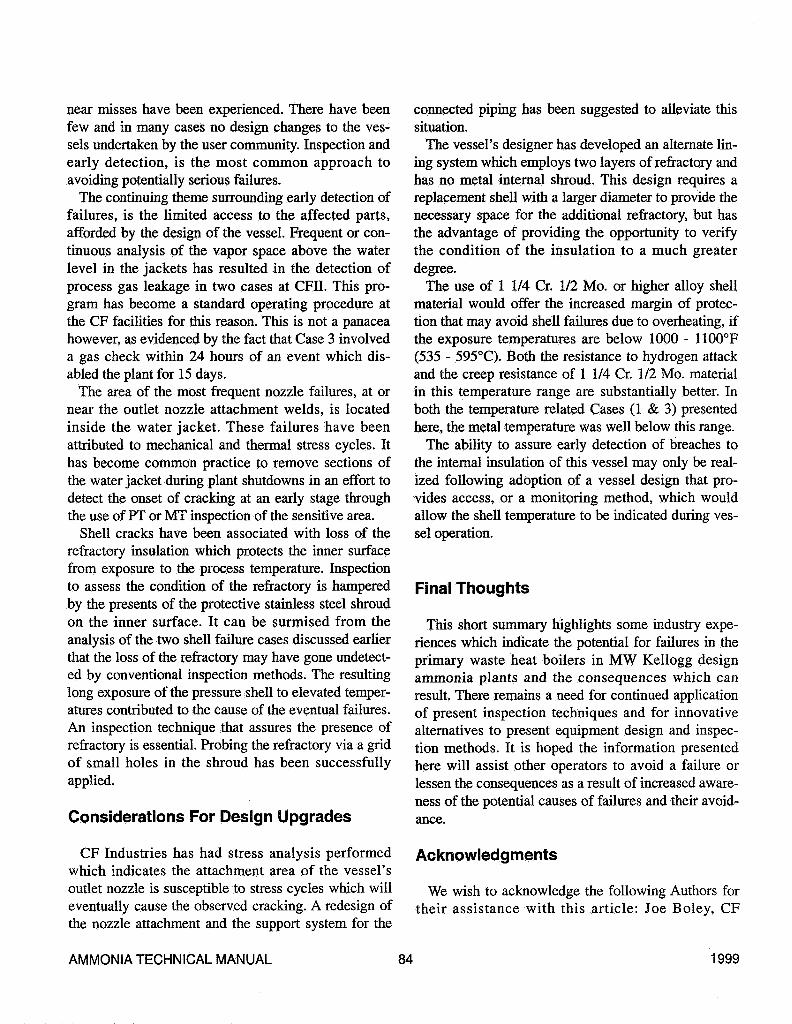
near misses have been experienced. There have beenfew and in many cases no design changes to the ves-sels undertaken by the user community. Inspection andearly detection, is the most common approach toavoiding potentially serious failures.
The continuing theme surrounding early detection offailures, is the limited access to the affected parts,afforded by the design of the vessel. Frequent or con-tinuous analysis of the vapor space above the waterlevel in the jackets has resulted -in the detection ofprocess gas leakage in two cases at CFÏÏ. This pro-gram has become a standard operating procedure atthe CF facilities for this reason. This is not a panaceahowever, as evidenced by the fact that Case 3 involveda gas check within 24 hours of an event which dis-abled the plant for 15 days.
The area of the most frequent nozzle failures, at ornear the outlet nozzle attachment welds, is locatedinside the water jacket. These failures have beenattributed to mechanical and thermal stress cycles. Ithas become common practice to remove sections ofthe water jacket during plant shutdowns in an effort todetect the onset of cracking at an early stage throughthe use of PT or MT inspection of the sensitive area.
Shell cracks have been associated with loss of therefractory insulation which protects the inner surfacefrom exposure to the process temperature. Inspectionto assess the condition of the refractory is hamperedby the presents of the protective stainless steel shroudon the inner surface. It can be surmised from theanalysis of the two shell failure cases discussed earlierthat the loss of the refractory may have gone undetect-ed by conventional inspection methods. The resultinglong exposure of the pressure shell to elevated temper-atures contributed to the cause of the eventual failures.An inspection technique that assures the presence ofrefractory is essential. Probing the refractory via a gridof small holes in the shroud has been successfullyapplied.
Considerations For Design Upgrades
CF Industries has had stress analysis performedwhich indicates the attachment area of the vessel'soutlet nozzle is susceptible to stress cycles which willeventually cause the observed cracking. A redesign ofthe nozzle attachment and the support system for the
connected piping has been suggested to alleviate thissituation.
The vessel's designer has developed an alternate lin-ing system which employs two layers of refractory andhas no metal internal shroud. This design requires areplacement shell with a larger diameter to provide thenecessary space for the additional refractory, but hasthe advantage of providing the opportunity to verifythe condition of the insulation to a much greaterdegree.
The use of 1 1/4 Cr. 1/2 Mo. or higher alloy shellmaterial would offer the increased margin of protec-tion that may avoid shell failures due to overheating, ifthe exposure temperatures are below 1000 - 1100°F(535 - 595°C). Both the resistance to hydrogen attackand the creep resistance of 1 1/4 Cr. 1/2 Mo. materialin this temperature range are substantially better. Inboth the temperature related Cases (1 & 3) presentedhere, the metal temperature was well below this range.
The ability to assure early detection of breaches tothe internal insulation of this vessel may only be real-ized following adoption of a vessel design that pro-vides access, or a monitoring method, which wouldallow the shell temperature to be indicated during ves-sel operation.
Final Thoughts
This short summary highlights some industry expe-riences which indicate the potential for failures in theprimary waste heat boilers in MW Kellogg designammonia plants and the consequences which canresult. There remains a need for continued applicationof present inspection techniques and for innovativealternatives to present equipment design and inspec-tion methods. It is hoped the information presentedhere will assist other operators to avoid a failure orlessen the consequences as a result of increased aware-ness of the potential causes of failures and their avoid-ance.
Acknowledgments
We wish to acknowledge the following Authors fortheir assistance with this article: Joe Boley, CF
AMMONIA TECHNICAL MANUAL 84 1999

Industries Inc., Donaldsonville, Louisiana - editorialassistance; Larry Cizmar, MW Kellogg - provided his-torical data, equipment and graphics Figures 2, 3; LenHodas, Mechanical & Materials Engineering (formerlyRadian Corporation) - provided file slides, 1986Canadian Fertilizers Ltd, Medicine Hat, Alberta, shellfailure analysis and valued advice; J. Yelverton, T.Pagendarm, CF Industries Inc.; Donaldsonville,Louisiana - vessel failure reports and supporting infor-mation.
Literature Cited
Hansen, D. E., "Stress and Flexibility Analysis ofPiping Systems and Vessel Shells (101CA &101CB)," Piping Analysis Inc. (1998)
Harding, S., "Failure Analysis, Primary Waste HeatBoiler, Canadian Fertilizers Ltd. Medicine HatAlberta," Radian Corp. (unpublished, 1987)
Hodas, L. J., Failure Analysis, 101CB Waste HeatExchanger Shell Unit No. 3 Ammonia Plant, CFIndustries Inc. Donaldsonville, LA, RadianInternational (unpublished., Jan. 1998).
Laing, K. (to R. D. Shannon), "Canadian FertilizersLtd, Medicine Hat Alberta, No. 2 Ammonia PlantShell failure report," (unpublished, Dec. 3, 1986).
Lapinskie, R. (to H. Matheson), "Canadian FertilizersLtd, Medicine Hat, Alberta 101C Failure and Repair
Report" (unpublished, 1987).Pagendarm, T., et al., "Incident Investigation No. 3
AIChE Ammonia Plant," CF Industries Inc.,Donaldsonville, LA (unpublished, April 1998)
Pagendarm, T., et al.,"Incident Investigation No. 3Ammonia Plant," CF Industries Inc.,Donaldsonville, LA,(unpublished, April 1998)
Shibasaki, T., et al., "Experience with Metal Dustingin H2/CO/CO2/H2O Atmosphere, Ammonia Plant
Safety & Related Facilities, Vol. 36, AIChE, NewYork (1996).
Stahl, H., and S. G. Thomsen "Survey of World WideExperience with Metal Dusting," Ammonia PlantSafety & Related Facilities, Vol. 36, AIChE, NewYork (1996)
Sutherland, L., "Failure Repair Report No. 1Ammonia Plant, 101C" CF Industries Inc.,Donaldsonville, LA (unpublished, Nov. 24, 1986).
Wagner, E. (to K. Laing), "Canadian Fertilizers Ltd,Medicine Hat, Alberta No. 2 Ammonia PlantShutdown Incident Report" (unpublished, Nov.14,1986).
White, M. T., "Stress Rupture of Boiler Shell,Scientific Testing Laboratories Inc." (unpublished,Dec. 11,1997).
Yelverton, J., CF Industries Inc., "Inspection / repairreport Donaldsonville, Louisiana / Radian,"(unpublished, 1997).
DISCUSSIONP. Khetarpal, Kribhco: I would like to know whetheryou have an inlet gas distributor within the waste heatboiler, and, if so, is there any problem with that?Jackson: We do not.Khetarpal: It's not there?Jackson: It's not there. It was originally provided, butit was removed, probably, within the first year of oper-ation and we haven't had one since.Khetarpal: We also faced a problem inside the wasteheat boiler. The liner inside shell got bulged. It ismaybe because of overheating or metal dusting. Linerbreaks very easily.
Jackson: Yes.Khetarpal: Do you suggest some improvement forthat?Jackson: I cannot. Our experience would be that thehot end of the exchangers in the inlet line and in thefirst 10 ft or so of the shell liner, maybe a little less,suffers from what I would call carburization. It getsbrittle and it cracks and what you have typically lastsin excess of five years. We've had some in servicemaybe ten years. I think our original installation was310 stainless in that area, and we've continued toreplace it with that. I really don't have an offering for,
AMMONIA TECHNICAL MANUAL 85 1999

or any experience with, any other material in that tells you right away.application. Jackson: How can you apply heat sensitive paint overHarry Van Praag, Terra Nitrogen: You were asking a water jacket?about monitoring of shell temperatures. We found heat Van Praag: I thought you said you wanted to do awaysensitive paint to be a very useful tool for finding any with the water jackets.minor refractory failures, and also major failures. It Jackson: Yes, indeed, heat sensitive paint is a great
idea if we can get ourselves a shell that's not jacketed.
AMMONIA TECHNICAL MANUAL 86 1999