1b - hp networking switch series security policy-(2013-10-21)a
TRANSCRIPT

Hewle5400/82 Module N HardwareSwitches: Modules: [1,3] or twJ9093A [3Plate (500J9712A [3J9723A [3Evident Se
Firmware
FIPS 14
FIPS Security Document Ve
tt-Pack200 zl Sw
Name: HP N
e Versions: (J8697A [(J8726A [wo [2,4]); 3,4] [A] [B]03-0753: o3] and J9713] and J972eal Kit: J97
Versions:
0-2 Non
Level: 2 ersion: 1.2.2
P
Hewlett-800Rose
U
Phone: http
kard Cowitch Se
Networkin
: 5406 zl [1], J8698A1,2] and twSupport M] [C]); Blanne [1,3] or3A [4]); H
24A [4]); w709A]) [1,2
K.15.07.00
n-Proprie
Prepared for:
-Packard Co0 Foothills Bl
evillle, CA 957United States
+1 (800) 334
p://www.hp.co
ompanyries
ng 5400 zl
1] 5412 zl A [2], J9447wo J9092AModule: (J9nk Plate: (5r two [2,4]
High Perforwith ([HP G2,3,4]
003 [A], K
etary Se
ompany lvd 747
4-5144 om
y
[1,2] and 8
[2], 8206 z7A [3] and
A [3,4] [A] 095A [3,4]5069-8563]); Opacityrmance FanGig-T/SFP+
K.15.07.001
ecurity P
1313
8200 zl [3,
zl [3], 8212 J9091A [4[B] [C]); P] [A] [B] [C
3: five [1,3]y Shield Kitn Trays: (J9+ V2 zl Mo
12 [B] and
olicy
P
Corse35 Lee Jackso
FairU
Phone: http://
4] Switch
2 zl [4] [A4] [A] [B] [Power SupC]); Fabric or elevents: (J9710A9721A [1],
od: J9536A]
K.15.09.00
Prepared by:
ec Security, on Memorial Hrfax, VA 2203United States
+1 (703) 267/www.corsec
Series
A] [B] [C]; [C]); Manaply: (J9306c Module: (n [2,4]); PSA [1], J971, J9722A [2] and [Tam
004[C]
Inc. Hwy., Suite 233
7-6050 .com
agement 6A: one (two U Blank 1A [2], 2],
mper
20

Security Policy, Version 1.2.1 October 18, 2013
HP 5400/8200 zl Switch Series Page 2 of 50
© Copyright 2012 Hewlett-Packard Development Company, L.P. This document may be freely reproduced and distributed whole and intact including this copyright notice.
Products indentified herein contain confidential commercial computer software. Valid license required.
Disclaimer The information contained in this document is subject to change without notice. HEWLLETT-PACKARD COMPANY MAKES NO WARRANTY OF ANY KIND WITH REGARD TO THIS MATERIAL, INCLUDING, BUT NOT LIMITED TO, THE IMPLIED WARRANTIES OF MERCHANTABILITY AND FITNESS FOR A PARTICULAR PURPOSE. Hewlett-Packard shall not be liable for errors contained herein or for incidental or consequential damages in connection with the furnishing, performance, or use of this material. The only warranties for HP products and services are set forth in the express warranty statements accompanying such products and services. Nothing herein should be constructed as constituting an additional warranty. HP shall not be liable for technical or editorial errors or omissions contained herein. Hewlett-Packard assumes no responsibility for the use or reliability of its software on equipment that is not furnished by Hewlett-Packard.

Security Policy, Version 1.2.1 October 18, 2013
HP 5400/8200 zl Switch Series Page 3 of 50
© Copyright 2012 Hewlett-Packard Development Company, L.P. This document may be freely reproduced and distributed whole and intact including this copyright notice.
Products indentified herein contain confidential commercial computer software. Valid license required.
Table of Contents 1 INTRODUCTION ...................................................................................................................... 5
1.1 PURPOSE ........................................................................................................................................................... 5 1.2 REFERENCES ...................................................................................................................................................... 5 1.3 DOCUMENT ORGANIZATION ........................................................................................................................ 5 1.4 DOCUMENT TERMINOLOGY ........................................................................................................................... 5
2 5400/8200 ZL SWITCH SERIES ............................................................................................... 7 2.1 OVERVIEW ........................................................................................................................................................ 7
2.1.1 HP 5400 zl Switch Series Cryptographic Modules ...................................................................................8 2.1.2 HP 8200 zl Switch Series Cryptographic Modules ...................................................................................8 2.1.3 5400/8200 zl Switch Series FIPS Security Levels .....................................................................................9
2.2 MODULE SPECIFICATION ............................................................................................................................... 10 2.3 MODULE INTERFACES .................................................................................................................................... 12
2.3.1 5400 zl Switch Series Ports and Interfaces ............................................................................................. 12 2.3.2 8200 zl Switch Series Ports and Interfaces ............................................................................................. 14 2.3.3 zl Interface Cards ............................................................................................................................................ 15
2.4 ROLES AND SERVICES .................................................................................................................................... 17 2.4.1 Crypto Officer Role ......................................................................................................................................... 18 2.4.2 User Role ........................................................................................................................................................... 19 2.4.3 Authentication .................................................................................................................................................. 20
2.5 PHYSICAL SECURITY ....................................................................................................................................... 20 2.6 OPERATIONAL ENVIRONMENT ..................................................................................................................... 20 2.7 CRYPTOGRAPHIC KEY MANAGEMENT ......................................................................................................... 21 2.8 SELF-TESTS ...................................................................................................................................................... 28
2.8.1 Power-Up Self-Tests ........................................................................................................................................ 28 2.8.2 Conditional Self-Tests ..................................................................................................................................... 28
2.9 MITIGATION OF OTHER ATTACKS ............................................................................................................... 28
3 SECURE OPERATION ............................................................................................................ 29 3.1 INITIAL APPLIANCE SETUP ............................................................................................................................. 29
3.1.1 Installation of High Performance Fan Tray .............................................................................................. 30 3.1.2 Installation of FIPS Opacity Shields ............................................................................................................ 30 3.1.3 Tamper-Evidence Label Placement ............................................................................................................ 32
3.2 INITIALIZATION OF FIPS MODE .................................................................................................................... 41 3.2.1 Pre-Initialization ............................................................................................................................................... 42 3.2.2 Initialization and Configuration ................................................................................................................... 43 3.2.3 Zeroization ........................................................................................................................................................ 46
3.3 SECURE MANAGEMENT ................................................................................................................................. 46 3.4 USER GUIDANCE ............................................................................................................................................ 46 3.5 BOOTROM GUIDANCE ................................................................................................................................ 46 3.6 PRODUCT DOCUMENTATION ...................................................................................................................... 47
4 ACRONYMS ............................................................................................................................. 48
Table of Figures FIGURE 1 – SAMPLE DEPLOYMENT FOR 5400/8200 ZL SWITCH SERIES .......................................................................... 7 FIGURE 2 – 5406 ZL SWITCH .............................................................................................................................................. 8 FIGURE 3 – 5412 ZL SWITCH .............................................................................................................................................. 8 FIGURE 4 – 8206 ZL SWITCH .............................................................................................................................................. 9 FIGURE 5 – 8212 ZL SWITCH .............................................................................................................................................. 9

Security Policy, Version 1.2.1 October 18, 2013
HP 5400/8200 zl Switch Series Page 4 of 50
© Copyright 2012 Hewlett-Packard Development Company, L.P. This document may be freely reproduced and distributed whole and intact including this copyright notice.
Products indentified herein contain confidential commercial computer software. Valid license required.
FIGURE 6 – 5406 ZL AND 5412 ZL CRYPTOGRAPHIC BOUNDARY ............................................................................... 10 FIGURE 7 – 8206 ZL AND 8212 ZL CRYPTOGRAPHIC BOUNDARY ............................................................................... 11 FIGURE 8 – SHIELD CLIP PLACEMENT ............................................................................................................................... 31 FIGURE 9 – RACK MOUNT BRACKET INSTALLATION ..................................................................................................... 31 FIGURE 10 – TAMPER-EVIDENCE LABEL PLACEMENT FOR 5400 ZL MANAGEMENT CARD.......................................... 32 FIGURE 11 – TAMPER-EVIDENCE LABEL PLACEMENT FOR 8200 ZL MANAGEMENT CARDS ........................................ 33 FIGURE 12 – TAMPER-EVIDENCE LABEL PLACEMENT FOR V2 ZL CARDS ....................................................................... 33 FIGURE 13 – TAMPER-EVIDENCE LABEL PLACEMENT FOR BLANK PLATES .................................................................... 33 FIGURE 14 – TAMPER-EVIDENCE LABEL PLACEMENT FOR 8200 ZL SYSTEM SUPPORT CARD ..................................... 34 FIGURE 15 – TAMPER-EVIDENCE LABEL PLACEMENT FOR 8200 ZL FABRIC CARDS ..................................................... 34 FIGURE 16 – 5400/8200 ZL TOP TAMPER-EVIDENCE LABEL PLACEMENT .................................................................... 35 FIGURE 17 – 5400/8200 ZL BOTTOM TAMPER-EVIDENCE LABEL PLACEMENT ............................................................ 36 FIGURE 18 – 5406 SIDE TAMPER-EVIDENCE LABEL PLACEMENT .................................................................................... 37 FIGURE 19 – 8206 SIDE TAMPER-EVIDENCE LABEL PLACEMENT .................................................................................... 37 FIGURE 20 – 5412 SIDE TAMPER-EVIDENCE LABEL PLACEMENT .................................................................................... 38 FIGURE 21 – 8212 SIDE TAMPER-EVIDENCE LABEL PLACEMENT .................................................................................... 38 FIGURE 22 – 5406ZL REAR TAMPER-EVIDENCE LABEL PLACEMENT .............................................................................. 39 FIGURE 23 – 8206 ZL REAR TAMPER-EVIDENCE LABEL PLACEMENT ............................................................................. 39 FIGURE 24 – 5412 ZL REAR TAMPER-EVIDENCE LABEL PLACEMENT ............................................................................. 40 FIGURE 25 – 8212 ZL REAR TAMPER-EVIDENCE LABEL PLACEMENT ............................................................................. 41
List of Tables TABLE 1 – FIPS 140-2 TERMINOLOGY COMPARISON ...................................................................................................... 6 TABLE 2 – SECURITY LEVEL PER FIPS 140-2 SECTION ...................................................................................................... 9 TABLE 3 – MAPPING OF FIPS 140-2 LOGICAL INTERFACES TO THE 5406 ZL SWITCH ............................................... 12 TABLE 4 – MAPPING OF FIPS 140-2 LOGICAL INTERFACES TO THE 5412 ZL SWITCH ............................................... 13 TABLE 5 – MAPPING OF FIPS 140-2 LOGICAL INTERFACES TO THE 8206 ZL SWITCH ............................................... 14 TABLE 6 – MAPPING OF FIPS 140-2 LOGICAL INTERFACES TO THE 8212 ZL SWITCH ............................................... 15 TABLE 7 – MAPPING OF FIPS 140-2 LOGICAL INTERFACES TO COMPATIBLE ZL INTERFACE CARDS ......................... 16 TABLE 8 – CRYPTO OFFICER SERVICES ............................................................................................................................. 18 TABLE 9 – USER SERVICES .................................................................................................................................................. 19 TABLE 10 – FIPS-APPROVED ALGORITHM IMPLEMENTATIONS ...................................................................................... 21 TABLE 11 – LIST OF CRYPTOGRAPHIC KEYS, CRYPTOGRAPHIC KEY COMPONENTS, AND CSPS .............................. 23 TABLE 12 – ACRONYMS .................................................................................................................................................... 48

Security Policy, Version 1.2.1 October 18, 2013
HP 5400/8200 zl Switch Series Page 5 of 50
© Copyright 2012 Hewlett-Packard Development Company, L.P. This document may be freely reproduced and distributed whole and intact including this copyright notice.
Products indentified herein contain confidential commercial computer software. Valid license required.
1 Introduction 1.1 Purpose This is a non-proprietary Cryptographic Module Security Policy for the 5400/8200 zl Switch Series from Hewlett-Packard Company This Security Policy describes how the 5400/8200 zl Switch Series meets the security requirements of Federal Information Processing Standards (FIPS) Publication 140-2, which details the U.S. and Canadian Government requirements for cryptographic modules. More information about the FIPS 140-2 standard and validation program is available on the National Institute of Standards and Technology (NIST) and the Communications Security Establishment Canada (CSEC) Cryptographic Module Validation Program (CMVP) website at http://csrc.nist.gov/groups/STM/cmvp. This document also describes how to run the module in a secure FIPS-Approved mode of operation. This policy was prepared as part of the Level 2 FIPS 140-2 validation of the module. The 5400/8200 zl Switch Series is referred to in this document as 5400/8200 zl switches, the switches, the cryptographic modules, or the modules.
1.2 References This document deals only with operations and capabilities of the module in the technical terms of a FIPS 140-2 cryptographic module security policy. More information is available on the module from the following sources:
The HP website (www.hp.com) contains information on the full line of products from HP. The CMVP website (http://csrc.nist.gov/groups/STM/cmvp/documents/140-1/140val-all.htm)
contains contact information for individuals to answer technical or sales-related questions for the module.
1.3 Document Organization The Security Policy document is one document in a FIPS 140-2 Submission Package. In addition to this document, the Submission Package contains:
Vendor Evidence document Finite State Model document Other supporting documentation as additional references
This Security Policy and the other validation submission documentation were produced by Corsec Security, Inc. under contract to HP. With the exception of this Non-Proprietary Security Policy, the FIPS 140-2 Submission Package is proprietary to HP and is releasable only under appropriate non-disclosure agreements. For access to these documents, please contact HP.
1.4 Document Terminology This document uses FIPS 140-2 terminology that slightly differs from terminology used in the HP Networking product documentation. Please use Table 1 as a reference to avoid confusion.

Security Policy, Version 1.2.1 October 18, 2013
HP 5400/8200 zl Switch Series Page 6 of 50
© Copyright 2012 Hewlett-Packard Development Company, L.P. This document may be freely reproduced and distributed whole and intact including this copyright notice.
Products indentified herein contain confidential commercial computer software. Valid license required.
Table 1 – FIPS 140-2 Terminology Comparison
FIPS 140-2 Terminology
HP Networking Equivalent
Cryptographic Module / Module
Refers to the cryptographic physical boundary, such as a 5406, 5412, 8206, 8212 zl Switch (for example, a ‘5406 cryptographic module’ or ‘5406 module’)
Cryptographic Officer (CO)
Refers to the system (cryptographic module) Manager
User Refers to a user with “Operator” privileges
operator Refers to an undefined user of the switch
Card Used in place of a ‘zl module’ that is installed in a zl switch, such as the zl Management Module, System Support zl Module, and v2 zl Modules. For example, “zl Management card” or “v2 zl card”.
Interface Refers to 1 of 5 FIPS 140-2 logical interfaces (Data in/out, Status out, Control in, Power)

Security Policy, Version 1.2.1 October 18, 2013
HP 5400/8200 zl Switch Series Page 7 of 50
© Copyright 2012 Hewlett-Packard Development Company, L.P. This document may be freely reproduced and distributed whole and intact including this copyright notice.
Products indentified herein contain confidential commercial computer software. Valid license required.
2 5400/8200 zl Switch Series
2.1 Overview The performance, features, and reliability of the 5400/8200 zl switches make them suitable for many applications throughout a network topology – from mission-critical enterprise-class access layer deployments to moderately sized core use models. The 5400/8200 zl Switch Series offer flexibility, in-chassis redundancy, and scalability in modular form factors. The 5400 zl Switch Series is available as a 4U or 7U rack mountable, modular chassis. The 5400 zl Switch Series provides Intelligent Edge features with baseline high availability in a modular form factor. The 8200 zl Switch Series is available as a 6U or 9U rack mountable, modular chassis. The 8200 zl Switch Series combines high performance with comprehensive networking and security features in a highly scalable, modular chassis solution. Together, the 5400/8200 zl switches offer a wide range of networking applications and services. Key features of the 5400/8200 zl Switch Series include:
Performance – High-capacity switching fabric Security – Virus throttling, detection of malicious attacks, and user access control Operational Flexibility – High port density, versatile intelligent ports, and optional service
modules Resiliency – Redundant power supplies, switch meshing, Virtual Router Redundancy Protocol
(VRRP), and redundant management and Fabric Cards (8200 zl series) Figure 1 shows a sample deployment scenario for the 5400/8200 zl Switch Series.
Figure 1 – Sample Deployment for 5400/8200 zl Switch Series

Security Policy, Version 1.2.1 October 18, 2013
HP 5400/8200 zl Switch Series Page 8 of 50
© Copyright 2012 Hewlett-Packard Development Company, L.P. This document may be freely reproduced and distributed whole and intact including this copyright notice.
Products indentified herein contain confidential commercial computer software. Valid license required.
2.1.1 HP 5400 zl Switch Series Cryptographic Modules The HP 5400 zl switches (Figure 2 and Figure 3) are the most advanced intelligent edge switches in the HP Networking product line. The 5400 zl Switch Series is available as a 4U (5406 zl) or 7U (5412 zl) rack mountable, modular chassis. The 5406 zl switch provides 6 interface card slots and the 5412 zl switch provides 12 interface card slots. With a wide variety of GbE and 10GbE interfaces as well as a choice of form factors, the 5400/8200 zl switches offer excellent flexibility and scalability as well as ease of deployment, operation, and maintenance.
Figure 2 – 5406 zl Switch
Figure 3 – 5412 zl Switch
The 5400 zl switches are targeted as enterprise and midmarket wiring closet switches – designed for low cost with a choice of medium to high port density. The 5400 zl switches offer extensive prioritization features that bring full convergence down to the desktop.
2.1.2 HP 8200 zl Switch Series Cryptographic Modules The 8200zl switches (Figure 4 and Figure 5) are some of the most advanced Layer 3/Layer 4 switches in the HP Networking product line. The 8200 zl switches incorporate a fully passive backplane and provide modular, redundant switch management and fabric. The 8200 zl Switch Series is available as a 6U (8206 zl) or 9U (8212 zl) rack mountable, modular chassis. The 8206 zl switch provides 6 interface card slots and the 8212 zl switch provides 12 interface card slots. With a wide variety of GbE interfaces, choice of PoE+ and non-PoE ports, and 10 GbE capabilities, the 8200 zl Switch Series offers excellent flexibility and scalability as well as ease of deployment, operation, and maintenance.
Security Policy, Version 1.2.1 October 18, 2013
HP 5400/8200 zl Switch Series Page 9 of 50
© Copyright 2012 Hewlett-Packard Development Company, L.P. This document may be freely reproduced and distributed whole and intact including this copyright notice.
Products indentified herein contain confidential commercial computer software. Valid license required.
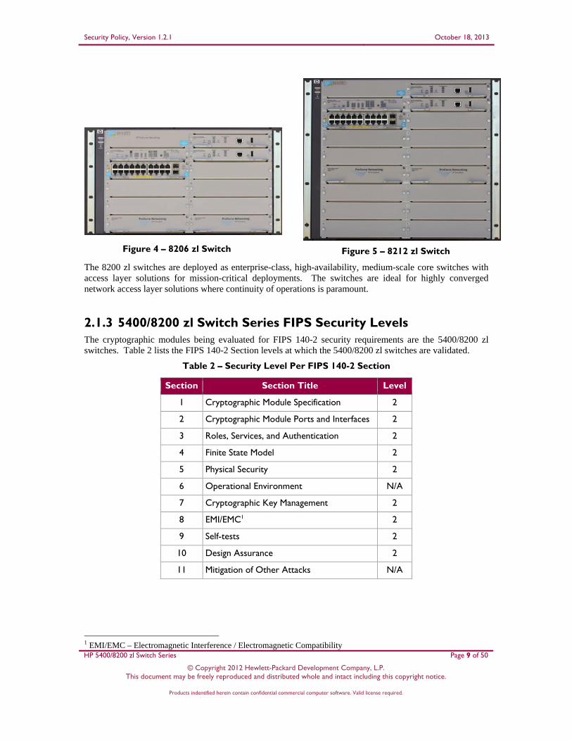
Figure 4 – 8206 zl Switch
Figure 5 – 8212 zl Switch
The 8200 zl switches are deployed as enterprise-class, high-availability, medium-scale core switches with access layer solutions for mission-critical deployments. The switches are ideal for highly converged network access layer solutions where continuity of operations is paramount.
2.1.3 5400/8200 zl Switch Series FIPS Security Levels The cryptographic modules being evaluated for FIPS 140-2 security requirements are the 5400/8200 zl switches. Table 2 lists the FIPS 140-2 Section levels at which the 5400/8200 zl switches are validated.
Table 2 – Security Level Per FIPS 140-2 Section
Section Section Title Level
1 Cryptographic Module Specification 2
2 Cryptographic Module Ports and Interfaces 2
3 Roles, Services, and Authentication 2
4 Finite State Model 2
5 Physical Security 2
6 Operational Environment N/A
7 Cryptographic Key Management 2
8 EMI/EMC1 2
9 Self-tests 2
10 Design Assurance 2
11 Mitigation of Other Attacks N/A
1 EMI/EMC – Electromagnetic Interference / Electromagnetic Compatibility

Security Policy, Version 1.2.1 October 18, 2013
HP 5400/8200 zl Switch Series Page 10 of 50
© Copyright 2012 Hewlett-Packard Development Company, L.P. This document may be freely reproduced and distributed whole and intact including this copyright notice.
Products indentified herein contain confidential commercial computer software. Valid license required.
2.2 Module Specification The cryptographic modules (5400/8200 zl switches) are hardware modules with multi-chip standalone embodiment. The overall security level of the switches is 2. The physical cryptographic boundary of the 5400/8200 zl switches is defined by the components that make up the exterior of each appliance. The FIPS validated configuration of the 5406 zl cryptographic module is shown in Figure 2 and consists of the following components:
Hard metal exterior making up the physical embodiment of each appliance (1) HP 5400 zl Management Card (1) HP 20-port Gig-T PoE+ / 2-port 10-GbE SFP+ v2 zl Card (1) HP 1500 W PoE+ zl Power Supply (1) HP 5406 zl High Performance Fan Tray (5) Metal blank plates for vacant slots (1) Metal PSU2 blank plate for vacant slot
The FIPS validated configuration of the 5412 zl cryptographic module is shown in Figure 3 and consists of the following components:
Hard metal exterior making up the physical embodiment of each appliance (1) HP 5400 zl Management Card (1) HP 20-port Gig-T PoE+ / 2-port 10-GbE SFP+ v2 zl Card (2) HP 1500 W PoE+ zl Power Supply (1) HP 5412 zl High Performance Fan Tray (11) Metal blank plates for vacant slots (2) Metal PSU blank plates for vacant slots
The physical cryptographic boundary of the 5400 zl switches is defined by the red dotted line in Figure 6.
Power Supply Unit(s)Management
Card
Interface Card
5406/5412 zl Switch
FanTray
Slot Covers
Figure 6 – 5406 zl and 5412 zl Cryptographic Boundary
2 PSU – Power Supply Unit

Security Policy, Version 1.2.1 October 18, 2013
HP 5400/8200 zl Switch Series Page 11 of 50
© Copyright 2012 Hewlett-Packard Development Company, L.P. This document may be freely reproduced and distributed whole and intact including this copyright notice.
Products indentified herein contain confidential commercial computer software. Valid license required.
The FIPS validated configuration of the 8206 zl cryptographic module is shown in Figure 4 and consists of the following components:
Hard metal exterior making up the physical embodiment of each appliance (2) HP 8200 zl Management Cards (2) HP 8200 zl Fabric Cards (1) HP 8200 zl System Support Card (1) HP 20-port Gig-T PoE+ / 2-port 10-GbE SFP+ v2 zl Card (1) HP 1500 W PoE+ zl Power Supply (1) HP 8206 zl High Performance Fan Tray (5) Metal blank plates for vacant slots (1) Metal PSU blank plate for vacant slot
The FIPS validated configuration of the 8212 zl cryptographic module is shown in Figure 5 and consists of the following components:
Hard metal exterior making up the physical embodiment of each appliance (2) HP 8200 zl Management Cards (2) HP 8200 zl Fabric Cards (1) HP 8200 zl System Support Card (1) HP 20-port Gig-T PoE+ / 2-port 10-GbE SFP+ v2 zl Card (2) HP 1500 W PoE+ zl Power Supplies (1) HP 8212 zl High Performance Fan Tray (11) Metal blank plates for vacant slots (2) Metal PSU blank plates for vacant slots
The physical cryptographic boundary of the 8200 zl switches is defined by the red dotted line in Figure 7.
Figure 7 – 8206 zl and 8212 zl Cryptographic Boundary

Security Policy, Version 1.2.1 October 18, 2013
HP 5400/8200 zl Switch Series Page 12 of 50
© Copyright 2012 Hewlett-Packard Development Company, L.P. This document may be freely reproduced and distributed whole and intact including this copyright notice.
Products indentified herein contain confidential commercial computer software. Valid license required.
2.3 Module Interfaces The 5406 zl, 5412 zl, 8206 zl, and 8212 zl cryptographic modules’ physical ports can be categorized into the following logical interfaces defined by FIPS 140-2:
Data Input Interface Data Output Interface Control Input Interface Status Output Interface Power Interface
2.3.1 5400 zl Switch Series Ports and Interfaces The 5406 zl and 5412 zl include the following logical interface items:
Management Card HP 20-port Gig-T PoE+3 / 2-port 10-GbE4 SFP+5 v2 zl interface card Power supplies High Performance Fan Tray
The power supplies and fan tray are located at the rear of the appliances. The Management Card consists of a CPU6, flash memory to hold the firmware image, processor memory for the code execution, status LEDs7, the cryptographic library, and other support circuitry to interface and control each interface card. The Management Card is the main driver of the 5400 zl switches, which oversees the operation of all zl interface cards. Figure 2 shows the front panel ports and interfaces of the 5406 zl switch.
The mapping of logical and physical interfaces to the FIPS validated configuration of the 5406 zl switch is detailed in Table 3.
Table 3 – Mapping of FIPS 140-2 Logical Interfaces to the 5406 zl Switch
Physical Interfacing Component
FIPS 140-2 Logical Interfaces
5406 zl Switch Port/Interface
(1) Management Card
Data Input (1) RS-2328 serial port (DB9)
Data Output (1) RS-232 serial port (DB9)
Control Input (1) RS-232 serial port (DB9), (1) Push Button
Status Output (1) RS-232 serial port (DB9), (32) LEDs
(1) HP 20-port Gig-T PoE+ / 2-port 10-GbE
SFP+ v2 zl interface card
Data Input (20) RJ9-45 Gig-T PoE+ ports, (2) SFP+ ports
Data Output (20) RJ-45 Gig-T PoE+ ports, (2) SFP+ ports
Control Input (20) RJ-45 Gig-T PoE+ ports
Status Output (20) RJ-45 Gig-T PoE+ ports, (2) SFP+ ports, (44) LED’s
Power Output (20) RJ-45 Gig-T PoE+ ports
3 PoE – Power over Ethernet 4 GbE – Gigabit Ethernet 5 SFP – Small Form-factor Pluggable 6 CPU – Central Processing Unit 7 LED – Light Emitting Diode 8 RS – Recommended Standard 9 RJ – Registered Jack

Security Policy, Version 1.2.1 October 18, 2013
HP 5400/8200 zl Switch Series Page 13 of 50
© Copyright 2012 Hewlett-Packard Development Company, L.P. This document may be freely reproduced and distributed whole and intact including this copyright notice.
Products indentified herein contain confidential commercial computer software. Valid license required.
Physical Interfacing Component
FIPS 140-2 Logical Interfaces
5406 zl Switch Port/Interface
(1) 1500 W PoE+ (110V/220V) Internal
Power Supplies
Power Input (1) AC10 Power Interface
Status Output (2) LED Indicators
(1) Status Panel Status Output (3) LED Indicators
(2) External Power Interfaces
Power Input (2) PoE Power Connector Interfaces
(1) High performance fan tray
Status Output (3) LED Indicators
Figure 3 shows the front panel ports and interfaces of the 5412 zl switch. The mapping of logical and physical interfaces to the FIPS validated configuration of the 5412 zl switch is detailed in Table 4.
Table 4 – Mapping of FIPS 140-2 Logical Interfaces to the 5412 zl Switch
Physical Interfacing Component
FIPS 140-2 Logical Interfaces 5412 zl Switch Port/Interface
(1) Management Card
Data Input (1) RS-232 serial port (DB9)
Data Output (1) RS-232 serial port (DB9)
Control Input (1) RS-232 serial port (DB9), (1) Push Button
Status Output (1) RS-232 serial port (DB9), (32) LEDs
(1) HP 20-port Gig-T PoE+ / 2-port 10-GbE
SFP+ v2 zl interface card
Data Input (20) RJ-45 Gig-T PoE+ ports, (2) SFP+ ports
Data Output (20) RJ-45 Gig-T PoE+ ports, (2) SFP+ ports
Control Input (20) RJ-45 Gig-T PoE+ ports
Status Output (20) RJ-45 Gig-T PoE+ ports, (2) SFP+ ports, (44) LED’s
Power Output (20) RJ-45 Gig-T PoE+ ports
(2) 1500 W PoE+ (110V/220V) Internal
Power Supplies
Power Input (2) AC Power Interfaces
Status Output (4) LED Indicators
(1) Status Panel Status Output (3) LED Indicators
(2) External Power Interfaces
Power Input (2) PoE Power Connector Interfaces
(1) High performance fan tray
Status Output (3) LED Indicators
10 AC – Alternating Current

Security Policy, Version 1.2.1 October 18, 2013
HP 5400/8200 zl Switch Series Page 14 of 50
© Copyright 2012 Hewlett-Packard Development Company, L.P. This document may be freely reproduced and distributed whole and intact including this copyright notice.
Products indentified herein contain confidential commercial computer software. Valid license required.
2.3.2 8200 zl Switch Series Ports and Interfaces The 8206 zl and 8212 zl modules include the following logical interface items:
Management Cards HP 20-port Gig-T PoE+ / 2-port 10-GbE SFP+ v2 zl interface card Fabric Cards System Support Card Power supplies High Performance Fan Tray
The Management Cards of the 8200 zl Switch Series are deployed as redundant cards for enhanced system availability. The cards will automatically synchronize configuration information and firmware images. The switching fabric of the 8200 zl modules is provided by the two Fabric Cards. The System Support Card provides a common area for system status LEDs. The System Support Card also provides a system clock, a multiplexor, and system status LEDs. Figure 4 shows the front panel ports and interfaces for the 8206 zl switch. The mapping of logical and physical interfaces to the FIPS validated configuration of the 8206 zl switch is detailed in Table 5.
Table 5 – Mapping of FIPS 140-2 Logical Interfaces to the 8206 zl Switch
Physical Interfacing Component
FIPS 140-2 Logical Interfaces
8206 zl Switch Port/Interface
(2) Management Card
Data Input (2) RS-232 serial port (RJ-45)
Data Output (2) RS-232 serial port (RJ-45)
Control Input (2) RS-232 serial port (RJ-45)
Status Output (2) RS-232 serial port (RJ-45) , (16) LEDs
(1) System Support Card Control Input (1) Push button
Status Out (29) LEDs
(1) HP 20-port Gig-T PoE+ / 2-port 10-GbE
SFP+ v2 zl interface card
Data Input (20) RJ-45 Gig-T PoE+ ports, (2) SFP+ ports
Data Output (20) RJ-45 Gig-T PoE+ ports, (2) SFP+ ports
Control Input (20) RJ-45 Gig-T PoE+ ports
Status Output (20) RJ-45 Gig-T PoE+ ports, (2) SFP+ ports, (44) LED’s
Power Output (20) RJ-45 Gig-T PoE+ ports
(1) 1500 W PoE+ (110V/220V) Internal
Power Supplies
Power Input (1) AC Power Interfaces
Status Output (2) LEDs
(1) Status Panel Status Output (3) LED Indicators
(2) External Power Interfaces
Power Input (2) PoE Power Connector Interfaces
(1) High performance fan tray
Status Output (3) LEDs
Security Policy, Version 1.2.1 October 18, 2013
HP 5400/8200 zl Switch Series Page 15 of 50
© Copyright 2012 Hewlett-Packard Development Company, L.P. This document may be freely reproduced and distributed whole and intact including this copyright notice.
Products indentified herein contain confidential commercial computer software. Valid license required.
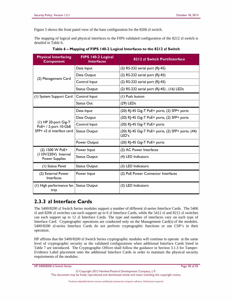
Figure 5 shows the front panel view of the base configuration for the 8206 zl switch. The mapping of logical and physical interfaces to the FIPS validated configuration of the 8212 zl switch is detailed in Table 6.
Table 6 – Mapping of FIPS 140-2 Logical Interfaces to the 8212 zl Switch
Physical Interfacing Component
FIPS 140-2 Logical Interfaces
8212 zl Switch Port/Interface
(2) Management Card
Data Input (2) RS-232 serial port (RJ-45)
Data Output (2) RS-232 serial port (RJ-45)
Control Input (2) RS-232 serial port (RJ-45)
Status Output (2) RS-232 serial port (RJ-45) , (16) LEDs
(1) System Support Card Control Input (1) Push button
Status Out (29) LEDs
(1) HP 20-port Gig-T PoE+ / 2-port 10-GbE
SFP+ v2 zl interface card
Data Input (20) RJ-45 Gig-T PoE+ ports, (2) SFP+ ports
Data Output (20) RJ-45 Gig-T PoE+ ports, (2) SFP+ ports
Control Input (20) RJ-45 Gig-T PoE+ ports
Status Output (20) RJ-45 Gig-T PoE+ ports, (2) SFP+ ports, (44) LED’s
Power Output (20) RJ-45 Gig-T PoE+ ports
(2) 1500 W PoE+ (110V/220V) Internal
Power Supplies
Power Input (2) AC Power Interfaces
Status Output (4) LED Indicators
(1) Status Panel Status Output (3) LED Indicators
(2) External Power Interfaces
Power Input (2) PoE Power Connector Interfaces
(1) High performance fan tray
Status Output (3) LED Indicators
2.3.3 zl Interface Cards The 5400/8200 zl Switch Series modules support a number of different zl-series Interface Cards. The 5406 zl and 8206 zl switches can each support up to 6 zl Interface Cards, while the 5412 zl and 8212 zl switches can each support up to 12 zl Interface Cards. The type and number of interfaces vary on each type of Interface Card. Cryptographic operations are conducted only on the Management Card(s) of the modules. 5400/8200 zl-series Interface Cards do not perform cryptographic functions or use CSP’s in their operation. HP affirms that the 5400/8200 zl Switch Series cryptographic modules will continue to operate at the same level of cryptographic security as the validated configurations when additional Interface Cards listed in Table 7 are introduced. The Cryptographic Officer shall follow the guidance in Section 3.1.3 for Tamper-Evidence Label placement onto the additional Interface Cards in order to maintain the physical security requirements of the modules.

Security Policy, Version 1.2.1 October 18, 2013
HP 5400/8200 zl Switch Series Page 16 of 50
© Copyright 2012 Hewlett-Packard Development Company, L.P. This document may be freely reproduced and distributed whole and intact including this copyright notice.
Products indentified herein contain confidential commercial computer software. Valid license required.
Table 7 lists the compatible zl interface cards for the 5400/8200 zl switches along with their associated ports and interfaces.
Table 7 – Mapping of FIPS 140-2 Logical Interfaces to Compatible zl interface cards
Card Name Supported FIPS 140-2 Logical Interfaces
Interface Card Ports/Interfaces
HP 20-port Gig-T PoE+ / 2-port 10GbE SFP+ v2
zl Card
Data In (20) RJ-45 Gig-T PoE+ ports, (2) SFP+ ports
Data Out (20) RJ-45 Gig-T PoE+ ports, (2) SFP+ ports
Control In (20) RJ-45 Gig-T PoE+ ports
Status Out (20) RJ-45 Gig-T PoE+ ports, (2) SFP+ ports, (44) LEDs
Power Out (20) RJ-45 Gig-T PoE+ ports
HP 24-port Gig-T PoE+ v2 zl Card
Data In (24) RJ-45 Gig-T PoE+ ports
Data Out (24) RJ-45 Gig-T PoE+ ports
Control In (24) RJ-45 Gig-T PoE+ ports
Status Out (24) RJ-45 Gig-T PoE+ ports, (48) LEDs
Power Out (24) RJ-45 Gig-T PoE+ ports
HP 20-port Gig-T PoE+ / 4-port SFP v2 zl Card
Data In (20) RJ-45 Gig-T PoE+ ports, (4) SFP ports
Data Out (20) RJ-45 Gig-T PoE+ ports, (4) SFP ports
Control In (20) RJ-45 Gig-T PoE+ ports
Status Out (20) RJ-45 Gig-T PoE+ ports, (4) SFP ports, (48) LEDs
Power Out (20) RJ-45 Gig-T PoE+ ports
HP 8-port 10GbE SFP+ v2 zl Card
Data In (8) SFP+ ports
Data Out (8) SFP+ ports
Status Out (8) SFP+ ports, (16) LEDs
HP 20-port Gig-T / 2-port 10GbE SFP+ v2 zl
Card
Data In (20) RJ-45 Gig-T ports, (2) SFP+ ports
Data Out (20) RJ-45 Gig-T ports, (2) SFP+ ports
Control In (20) RJ-45 Gig-T ports
Status Out (20) RJ-45 Gig-T ports, (2) SFP+ ports, (44) LEDs
HP 24-port SFP v2 zl Card
Data In (24) SFP ports
Data Out (24) SFP ports
Control In (24) SFP ports
Status Out (24) SFP ports, (48) LEDs
Security Policy, Version 1.2.1 October 18, 2013
HP 5400/8200 zl Switch Series Page 17 of 50
© Copyright 2012 Hewlett-Packard Development Company, L.P. This document may be freely reproduced and distributed whole and intact including this copyright notice.
Products indentified herein contain confidential commercial computer software. Valid license required.
HP 8-port 10Gbase-T v2 zl Card
Data In (8) 10GBase-T ports
Data Out (8) 10GBase-T ports
Control In (8) 10GBase-T ports
Status Out (8) 10GBase-T ports, (16) LEDs
HP 24-port 10/100 PoE+ v2 zl Card
Data In (24) RJ-45 10/100BaseT PoE+ ports
Data Out (24) RJ-45 10/100BaseT PoE+ ports
Control In (24) RJ-45 10/100BaseT PoE+ ports
Status Out (24) RJ-45 10/100BaseT PoE+ ports, (48) LEDs
Power Out (24) RJ-45 10/100BaseT PoE+ ports
HP 24-port Gig-T v2 zl Card
Data In (24) RJ-45 Gig-T ports
Data Out (24) RJ-45 Gig-T ports
Control In (24) RJ-45 Gig-T ports
Status Out (24) RJ-45 Gig-T ports, (48) LEDs
HP 20-port Gig-T / 4-port SFP v2 zl Card
Data In (20) RJ-45 Gig-T ports, (4) SFP ports
Data Out (20) RJ-45 Gig-T ports, (4) SFP ports
Control In (20) RJ-45 Gig-T ports
Status Out (20) RJ-45 Gig-T ports, (4) SFP ports, (48) LEDs
HP 12-port Gig-T PoE+ / 12-port SFP v2 zl Card
Data In (12) RJ-45 Gig-T PoE+ ports, (12) SFP ports
Data Out (12) RJ-45 Gig-T PoE+ ports
Control In (12) RJ-45 Gig-T PoE+ ports, (12) SFP ports
Status Out (12) RJ-45 Gig-T PoE+ ports, (12) SFP ports, (48) LEDs
Power Out (12) RJ-45 Gig-T PoE+ ports
2.4 Roles and Services Each cryptographic module supports two roles (as required by FIPS 140-2) that an operator can assume: a Crypto Officer (Manager) role and a User (Operator) role. Each role is accessed through proper role-based authentication to the switch. Services associated with each role are listed in the following sections. Please note that the keys and CSPs11 listed in Table 8 and Table 9 indicate the type of access required using the following notation:
R – Read: The CSP is read. W – Write: The CSP is established, generated, modified, or zeroized. X – Execute: The CSP is used within an Approved or Allowed security function or authentication
mechanism
11 CSP – Critical Security Parameter

Security Policy, Version 1.2.1 October 18, 2013
HP 5400/8200 zl Switch Series Page 18 of 50
© Copyright 2012 Hewlett-Packard Development Company, L.P. This document may be freely reproduced and distributed whole and intact including this copyright notice.
Products indentified herein contain confidential commercial computer software. Valid license required.
2.4.1 Crypto Officer Role The Crypto Officer (CO) is responsible for the set up and initialization of the 5400/8200 zl switches as documented in Section 3 (Secure Operation) of this document. The CO has complete control of the switches and is in charge of configuring all of the settings for each switch. The CO can create RSA12 key pairs for SSH v213. Private keys and CSPs can be viewed by the CO. The CO is also in charge of maintaining access control and checking error and intrusion logs. Descriptions of the services available to the Crypto Officer role are provided in Table 8 below.
Table 8 – Crypto Officer Services
Service Description CSP and Type of Access
Configure Switch Configuration of CSPs for normal switch operation
Port Access Password – W SNMPv314 Authentication/Privacy Passwords – W Global RADIUS15 Server Shared Secret – W RADIUS Server Host Shared Secret – W TACACS16 Server Shared Secret – W TACACS Server Host Shared Secret – W ‘Key-chain’ Key Strings– W SNTP 17 Shared Secret – W VLAN18 OSPF Shared Secret – W VLAN RIP19 Shared Secret – W SSH v2 Private/Public Keys – W Encrypt Credentials Encryption Key – W CO Password – W User Password – W ROM20 Console Password – W
Manage Passwords Manage CO, User, and BootROM passwords
CO Password – W User Password – W ROM Console Password – W
Initiate Enhanced Secure-Mode (FIPS capable mode)
Reboot the system into a FIPS-Approved mode of operation
All Keys – W
Initiate Standard Secure-Mode (non-FIPS capable mode)
Reboot the system into a non-FIPS Approved mode of operation
All Keys – W
Zeroization Zeroize all keys and CSPs All Keys – W
Verify Image Signature On demand firmware image integrity check
Image Signature – R Image Verification Public Key – X
12 RSA – Rivest, Shamir, Adleman 13 SSH – Secure Shell 14 SNMP – Secure Network Management Protocol 15 RADIUS – Remote Access Dial-in User Service 16 TACACS – Terminal Access Controller Access-Control System 17 SNTP – Simple Network Transfer Protocol 18 VLAN – Virtual Local Area Network 19 RIP – Routing Information Protocol 20 ROM – Read Only Memory
Security Policy, Version 1.2.1 October 18, 2013
HP 5400/8200 zl Switch Series Page 19 of 50
© Copyright 2012 Hewlett-Packard Development Company, L.P. This document may be freely reproduced and distributed whole and intact including this copyright notice.
Products indentified herein contain confidential commercial computer software. Valid license required.
Service Description CSP and Type of Access
Show CSPs Display keys and CSPs Global RADIUS Server Shared Secret – R RADIUS Server Host Shared Secret – R TACACS Server Encryption Key – R TACACS Server Host Shared Secret – R Key-chain Key String – R Router OSPF Shared Secret – R VLAN OSPF Shared Secret – R VLAN RIP Shared Secret – R Port Access Password – R
Establish SSH v2 Connection
Establish a remote SSH v2 session with the switch
CO Password – X SSH v2 Public/Private Key – X SSH v2 Session Key – WRX Diffie-Hellman Public/Private Key – WRX
Reboot/On Demand Self-Tests
Reboot the switch; perform self-tests on demand
None
Show Secure-Mode Display the current secure mode of the switch
None
Control Chassis LED Control the “Chassis Locate” LED
None
View Logs View syslog for system status, warnings, and errors
None
2.4.2 User Role The User role can verify the firmware image signature on-demand, show the current secure-mode of the switch, view the syslog, and connect to the switch remotely via SSH v2. Descriptions of the services available to the User role are provided in Table 9.
Table 9 – User Services
Service Description CSP and Type of Access
Verify Image Signature On demand firmware image integrity check
Image Signature – R Image Verification Public Key – X
Establish SSH v2 Connection
Establish a remote SSH v2 session with the module
User Password – X SSH v2 Public/Private Key – RX SSH v2 Session Key – WRX Diffie-Hellman Public/Private Key – WRX
Show secure-mode Display the current secure mode of the module
None
Control Chassis LED Control the “Chassis Locate” LED
None
View Logs View syslog for system status, warnings, and errors
None

Security Policy, Version 1.2.1 October 18, 2013
HP 5400/8200 zl Switch Series Page 20 of 50
© Copyright 2012 Hewlett-Packard Development Company, L.P. This document may be freely reproduced and distributed whole and intact including this copyright notice.
Products indentified herein contain confidential commercial computer software. Valid license required.
2.4.3 Authentication The 5400/8200 zl switches support role-based authentication to control access to all services provided by the switches. To perform services on the switches, an operator must log in to the switch by authenticating with the respective role’s username and secure password. The CO or User password is only known by those that are associated with that role. The CO and User passwords are initialized by the CO as part of switch initialization, as described in Section 3 (Secure Operation) of this document. Once the operator is authenticated, they will assume their respective role and will be able to carry out the available services listed in Table 8 and Table 9.
2.4.3.1 Authentication Data Protection
The 5400/8200 zl switches do not allow the disclosure, modification, or substitution of authentication data to unauthorized operators. Authentication data can only be modified by the operator who has assumed the CO role.
2.4.3.2 Authentication Mechanism Strength
The 5400/8200 zl switches require a minimum of 8 characters and a maximum of 64 characters for a password. The password may contain any combination of letters, numbers, and special characters (not including ‘space’) allowing for a total of 94 possible characters. Therefore, there is, at a minimum 948 = 6,095,689,385,410,816 possible character combinations. This means there is a 1 in 6,095,689,385,410,816 chance that random access will succeed, surpassing the 1 in 1,000,000 requirements.
The module requires an 8 character password with 94 possible characters per password character; therefore requiring 948/100,000 = 6.1x10¹⁰ password attempts in 60 seconds to surpass the 1:100,000 ratio. The processor speed is 666MHz, translating to 1.5x10⁻⁹ seconds per cycle. Assuming worst case scenario and no overhead, to process (6.1x10¹⁰ passwords * 8 bits = ) 4.88x1011 bits of data, it would take the processor ((4.88x1011 bits x 1.5x10⁻⁹ seconds per cycle)/8 bits per cycle=) 91 seconds to process all 6.1x10¹⁰ password attempts. Therefore the password strengths meet FIPS 140-2 requirements.
2.5 Physical Security The 5400/8200 zl Switch Series are multi-chip standalone cryptographic modules. The modules consist of production-grade components that include standard passivation techniques. The chassis, interface card covers, blank plates, power supplies, and fan tray of the 5400/8200 zl switches are made of a hard metal, opaque within the visible spectrum. All ventilation holes present on the modules have either been covered by Tamper-Evidence Labels or an opacity shield, rendering them incapable of disclosing any security-relevant components when inspected. The modules contain removable covers, zl interface cards, power supplies, and fan tray; all of which are protected by Tamper-Evidence Labels. Correct placement of Tamper-Evidence Labels onto each of the modules is covered in the Section 3 (Secure Operation) of this document.
2.6 Operational Environment The operational environment running within the 5400/8200 zl switches consists of the Greenhills Integrity Operating System running the latest management firmware (HP K.15.07.0003, K.15.07.0012, K.15.09.0004). The operational environment of the switches is non-modifiable, thus the operational environment requirements do not apply to the 5400/8200 zl switches.
Security Policy, Version 1.2.1 October 18, 2013
HP 5400/8200 zl Switch Series Page 21 of 50
© Copyright 2012 Hewlett-Packard Development Company, L.P. This document may be freely reproduced and distributed whole and intact including this copyright notice.
Products indentified herein contain confidential commercial computer software. Valid license required.
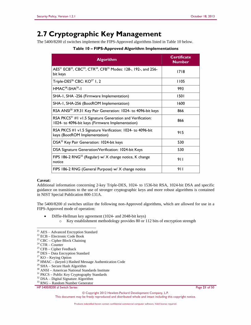
2.7 Cryptographic Key Management The 5400/8200 zl switches implement the FIPS-Approved algorithms listed in Table 10 below.
Table 10 – FIPS-Approved Algorithm Implementations
Algorithm Certificate Number
AES21 ECB22, CBC23, CTR24, CFB25 Modes: 128-, 192-, and 256-bit keys 1718
Triple-DES26 CBC: KO27 1, 2 1105
HMAC28-SHA29-1 993
SHA-1, SHA -256 (Firmware Implementation) 1501
SHA-1, SHA-256 (BootROM Implementation) 1600
RSA ANSI30 X9.31 Key Pair Generation: 1024- to 4096-bit keys 866
RSA PKCS31 #1 v1.5 Signature Generation and Verification: 1024- to 4096-bit keys (Firmware Implementation) 866
RSA PKCS #1 v1.5 Signature Verification: 1024- to 4096-bit keys (BootROM Implementation)
915
DSA32 Key Pair Generation: 1024-bit keys 530
DSA Signature Generation/Verification: 1024-bit Keys 530
FIPS 186-2 RNG33 (Regular) w/ X change notice, K change notice
911
FIPS 186-2 RNG (General Purpose) w/ X change notice 911
Caveat: Additional information concerning 2-key Triple-DES, 1024- to 1536-bit RSA, 1024-bit DSA and specific guidance on transitions to the use of stronger cryptographic keys and more robust algorithms is contained in NIST Special Publication 800-131A.
The 5400/8200 zl switches utilize the following non-Approved algorithms, which are allowed for use in a FIPS-Approved mode of operation:
Diffie-Hellman key agreement (1024- and 2048-bit keys) o Key establishment methodology provides 80 or 112 bits of encryption strength
21 AES – Advanced Encryption Standard 22 ECB – Electronic Code Book 23 CBC – Cipher Block Chaining 24 CTR – Counter 25 CFB – Cipher Feedback 26 DES – Data Encryption Standard 27 KO – Keying Option 28 HMAC – (keyed-) Hashed Message Authentication Code 29 SHA – Secure Hash Algorithm 30 ANSI – American National Standards Institute 31 PKCS – Public Key Cryptography Standards 32 DSA – Digital Signature Algorithm 33 RNG – Random Number Generator

Security Policy, Version 1.2.1 October 18, 2013
HP 5400/8200 zl Switch Series Page 22 of 50
© Copyright 2012 Hewlett-Packard Development Company, L.P. This document may be freely reproduced and distributed whole and intact including this copyright notice.
Products indentified herein contain confidential commercial computer software. Valid license required.
Message Digest 5 (MD5) o Message authentication for use with OSPF, BGP, RADIUS, TACACS, and RIP

Security Policy, Version 1.2.1 October 18, 2013
HP 5400/8200 zl Switch Series Page 23 of 50
© Copyright 2011 Hewlett-Packard Development Company, L.P. This document may be freely reproduced and distributed whole and intact including this copyright notice.
Products indentified herein contain confidential commercial computer software. Valid license required.
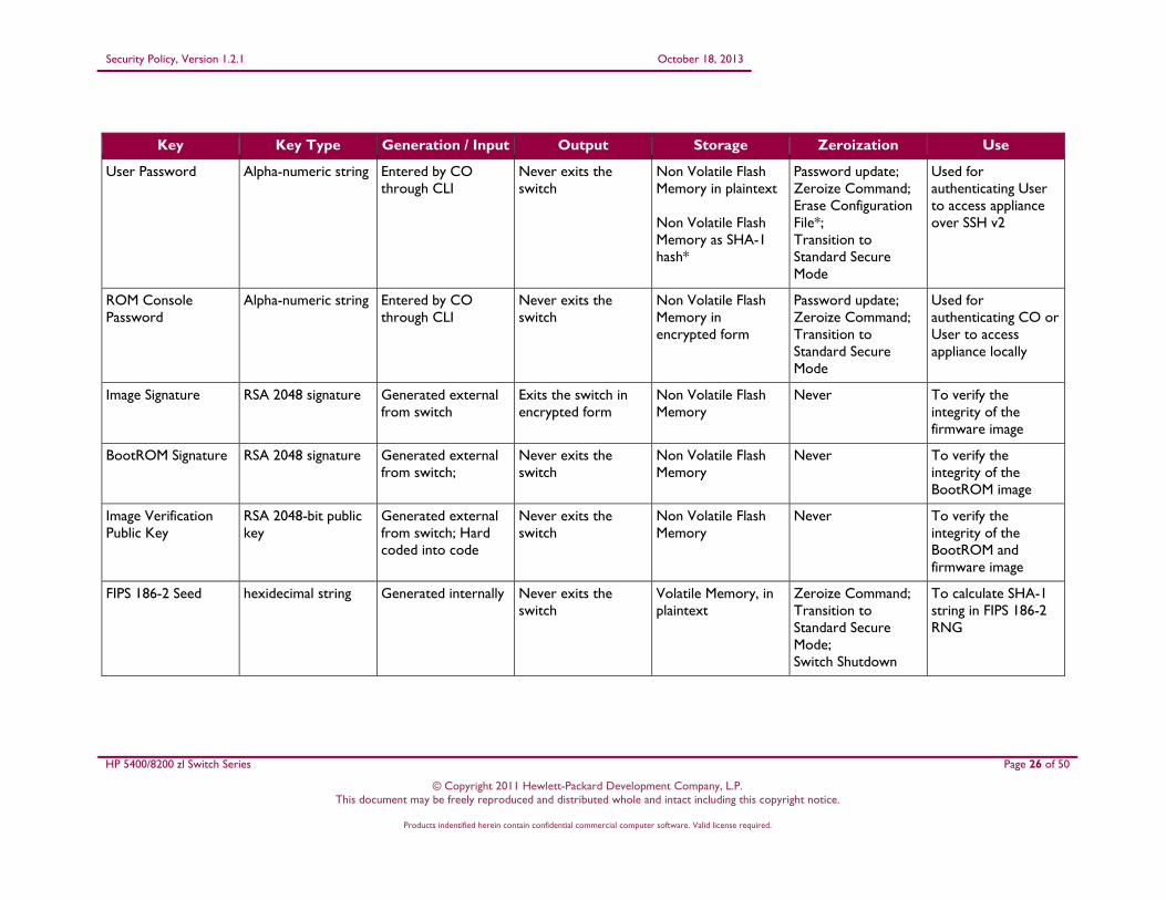
The 5400/8200 zl switches support the critical security parameters (CSPs) listed below in Table 11.
Table 11 – List of Cryptographic Keys, Cryptographic Key Components, and CSPs
Key Key Type Generation / Input Output Storage Zeroization Use
Port Access Password
Alpha-numeric string Entered by CO through CLI
Exits in plaintext using CLI command
Non Volatile Flash Memory in plaintext
Password Update; Erase Configuration File*; Zeroize Command; Transition to Standard Secure Mode
Authenticate client device that wishes to access the LAN34
SNMPv3 Authentication Password
Alpha-numeric string Entered by CO through CLI
Never exits the switch
Non Volatile Flash Memory in plaintext
Zeroize Command; Erase Configuration File; Transition to Standard Secure Mode
To ensure message integrity and protection against message replay
SNMPv3 Privacy Password
Alpha-numeric string Entered by CO through CLI
Never exits the switch
Non Volatile Flash Memory in plaintext
Zeroize Command; Erase Configuration File; Transition to Standard Secure Mode
To ensure packet contents are not disclosed on a network
Global RADIUS Server Shared Secret
Alpha-numeric string Entered by CO through CLI
Exits in plaintext using CLI command
Non Volatile Flash Memory in plaintext
Zeroize Command; Erase Configuration File; Transition to Standard Secure Mode
A shared secret between switches and RADIUS servers to sign all packets
34LAN – Local Area Network

Security Policy, Version 1.2.1 October 18, 2013
HP 5400/8200 zl Switch Series Page 24 of 50
© Copyright 2011 Hewlett-Packard Development Company, L.P. This document may be freely reproduced and distributed whole and intact including this copyright notice.
Products indentified herein contain confidential commercial computer software. Valid license required.
Key Key Type Generation / Input Output Storage Zeroization Use
RADIUS Server Host Shared Secret
Alpha-numeric string Entered by CO through CLI
Exits in plaintext using CLI command
Non Volatile Flash Memory in plaintext
Zeroize Command; Erase Configuration File; Transition to Standard Secure Mode
A shared secret between switches and a specific RADIUS server to sign all packets
TACACS Server Encryption Key
Alpha-numeric string Entered by CO through CLI
Exits in plaintext using CLI command
Non Volatile Flash Memory in plaintext
Zeroize Command; Erase Configuration File; Transition to Standard Secure Mode
A shared secret to remote TACACS server
TACACS Server Host Shared Secret
Alpha-numeric string Entered by CO through CLI
Exits in plaintext using CLI command
Non Volatile Flash Memory in plaintext
Zeroize Command; Erase Configuration File; Transition to Standard Secure Mode
A shared secret to local TACACS server
Key-chain Key Strings
String of assorted keys
Entered by CO through CLI
Exits in plaintext using CLI command
Non Volatile Flash Memory in plaintext
Zeroize Command; Erase Configuration File; Transition to Standard Secure Mode
Set of keys with a timing mechanism for activating and deactivating individual keys
SNTP Shared Secret Alpha-numeric string Entered by CO through CLI
Never exits the switch
Non Volatile Flash Memory in plaintext
Zeroize Command; Erase Configuration File; Transition to Standard Secure Mode
Authentication key for accessing remote SNTP server

Security Policy, Version 1.2.1 October 18, 2013
HP 5400/8200 zl Switch Series Page 25 of 50
© Copyright 2011 Hewlett-Packard Development Company, L.P. This document may be freely reproduced and distributed whole and intact including this copyright notice.
Products indentified herein contain confidential commercial computer software. Valid license required.
Key Key Type Generation / Input Output Storage Zeroization Use
Router OSPF Shared Secret
Alpha-numeric string Entered by CO through CLI
Exits in plaintext using CLI command
Non Volatile Flash Memory in plaintext
Zeroize Command; Erase Configuration File; Transition to Standard Secure Mode
Exchange routing update information securely
VLAN OSPF Shared Secret
Alpha-numeric string Entered by CO through CLI
Exits in plaintext using CLI command
Non Volatile Flash Memory in plaintext
Zeroize Command; Erase Configuration File; Transition to Standard Secure Mode
Exchange routing update information securely
VLAN RIP Shared Secret
Alpha-numeric string Entered by CO through CLI
Exits in plaintext using CLI command
Non Volatile Flash Memory in plaintext
Zeroize Command; Erase Configuration File; Transition to Standard Secure Mode
Exchange routing update information securely
Encrypt Credentials Encryption Key
FIPS 140-2 non-approved encryption key
Entered by CO through CLI
Exits in plaintext using CLI command
Non Volatile Flash Memory in plaintext
Zeroize Command; Transition to Standard Secure Mode
Key used to obfuscate keys stored in the ‘config’ file
CO Password Alpha-numeric string Entered by CO through CLI
Never exits the switch
Non Volatile Flash Memory in plaintext; Non Volatile Flash Memory as SHA-1 hash*
Password update; Zeroize Command; Erase Configuration File*; Transition to Standard Secure Mode
Used for authenticating CO to access appliance locally or over SSH v2
Security Policy, Version 1.2.1 October 18, 2013
HP 5400/8200 zl Switch Series Page 26 of 50
© Copyright 2011 Hewlett-Packard Development Company, L.P. This document may be freely reproduced and distributed whole and intact including this copyright notice.
Products indentified herein contain confidential commercial computer software. Valid license required.
Key Key Type Generation / Input Output Storage Zeroization Use
User Password Alpha-numeric string Entered by CO through CLI
Never exits the switch
Non Volatile Flash Memory in plaintext Non Volatile Flash Memory as SHA-1 hash*
Password update; Zeroize Command; Erase Configuration File*; Transition to Standard Secure Mode
Used for authenticating User to access appliance over SSH v2
ROM Console Password
Alpha-numeric string Entered by CO through CLI
Never exits the switch
Non Volatile Flash Memory in encrypted form
Password update; Zeroize Command; Transition to Standard Secure Mode
Used for authenticating CO or User to access appliance locally
Image Signature RSA 2048 signature Generated external from switch
Exits the switch in encrypted form
Non Volatile Flash Memory
Never To verify the integrity of the firmware image
BootROM Signature RSA 2048 signature Generated external from switch;
Never exits the switch
Non Volatile Flash Memory
Never To verify the integrity of the BootROM image
Image Verification Public Key
RSA 2048-bit public key
Generated external from switch; Hard coded into code
Never exits the switch
Non Volatile Flash Memory
Never To verify the integrity of the BootROM and firmware image
FIPS 186-2 Seed hexidecimal string Generated internally Never exits the switch
Volatile Memory, in plaintext
Zeroize Command; Transition to Standard Secure Mode; Switch Shutdown
To calculate SHA-1 string in FIPS 186-2 RNG

Security Policy, Version 1.2.1 October 18, 2013
HP 5400/8200 zl Switch Series Page 27 of 50
© Copyright 2011 Hewlett-Packard Development Company, L.P. This document may be freely reproduced and distributed whole and intact including this copyright notice.
Products indentified herein contain confidential commercial computer software. Valid license required.
Key Key Type Generation / Input Output Storage Zeroization Use
FIPS 186-2 Seed Key SHA-1 Digest Generated Internally Never exits the switch
Volatile Memory, in plaintext
Zeroize Command; Transition to Standard Secure Mode; Switch Shutdown
To calculate SHA-1 string in FIPS 186-2 RNG
SSH v2 Public Key RSA 3072-bit Public key
Generated Internally Exits the switch in plaintext
Non Volatile Flash Memory
Zeroize Command; Transition to Standard Secure Mode
SSH v2 server authentication
SSH v2 Private Key RSA 3072-bit Private key
Generated internally Never exits the switch
Non Volatile Flash Memory
Zeroize Command; Transition to Standard Secure Mode
SSH v2 server authentication
SSH v2 Session Key Shared symmetric key
Generated internally Never exits the switch
Volatile Memory, in plaintext
Zeroize Command; Terminate session; Switch Shutdown
encrypting/decrypting the data traffic during the SSH v2 session
Diffie-Hellman Key Agreement Private Key
Diffie-Hellman Private Key
Generated internally Never exits the switch
Volatile Memory, in plaintext
Zeroize Command; Terminate session; Switch Shutdown
Securely exchange information over SSH v2
Diffie-Hellman Key Agreement Public Key
Diffie-Hellman Public Key
Generated internally Exits the switch in plaintext
Volatile Memory, in plaintext
Zeroize Command; Terminate session; Switch Shutdown
Securely exchange information over SSH v2
BGP Neighbor password
Alpha-numeric key string
Entered by CO through CLI
Exits in plaintext using CLI command
Non Volatile Flash Memory in plaintext
Zeroize Command; Erase Configuration File; Transition to Standard Secure Mode
Exchange routing update information securely
* = The CO has executed the include-credentials store-in-config command

Security Policy, Version 1.2.1 October 18, 2013
HP 5400/8200 zl Switch Series Page 28 of 50
© Copyright 2012 Hewlett-Packard Development Company, L.P. This document may be freely reproduced and distributed whole and intact including this copyright notice.
Products indentified herein contain confidential commercial computer software. Valid license required.
2.8 Self-Tests The 5400/8200 zl Switch Series modules perform cryptographic self-tests during power-up and as needed while performing a Crypto Officer service. The purpose of these self-tests is to verify functionality and correctness of the cryptographic algorithms listed in Table 10. Should any of the power-up self-tests or conditional self-tests fail, the modules will cease operation, inhibiting all data output from the modules. The modules will automatically reboot and perform power-up self-tests. Successful completion of the power-up self-tests will return the module to normal operation.
2.8.1 Power-Up Self-Tests Power-up self-tests are performed when the 5400/8200 zl switches first power up. There are two instances of power-up self-tests that are performed. The first instance is performed by the BootROM image. The BootROM, used for the selection of a cryptographic firmware image, performs the following self-tests:
Known Answer Tests (KATs) o SHA-1 KAT o SHA-256 KAT o RSA Pariwise Consistency Test
BootROM integrity check Firmware integrity check (after image has been selected)
The BootROM performs the integrity check on itself to ensure that its image is valid. To perform an integrity check on itself, as well as on images that can be downloaded within, the BootROM needs to first perform RSA signature verification, and then check the SHA-256 hash of the image. If the BootROM integrity check fails, the switch shall be returned to HP. If the firmware integrity check fails, the switch will transition to the BootROM console where a new image with a valid signature can be downloaded. The second instance of power-up self-tests the 5400/8200 zl switches perform are done once a FIPS Approved image has been loaded by the BootROM and are performed by that image:
Known Answer Tests (KATs) o AES KAT o Triple-DES KAT o RSA Pairwise Consistency Test o DSA Pairwise Consistency Test o SHA-1 KAT o SHA-256 KAT o HMAC SHA-1 KAT o FIPS 186-2 Random Number Generator KAT
2.8.2 Conditional Self-Tests The 5400/8200 zl switches perform the following conditional self-tests:
Continuous RNG test RSA Pairwise Consistency Test DSA Pairwise Consistency Test Firmware load test
2.9 Mitigation of Other Attacks This section is not applicable. The modules do not claim to mitigate any attacks beyond the FIPS 140-2 Level 2 requirements for this validation.

Security Policy, Version 1.2.1 October 18, 2013
HP 5400/8200 zl Switch Series Page 29 of 50
© Copyright 2012 Hewlett-Packard Development Company, L.P. This document may be freely reproduced and distributed whole and intact including this copyright notice.
Products indentified herein contain confidential commercial computer software. Valid license required.
3 Secure Operation The 5400/8200 zl switches meet Level 2 requirements for FIPS 140-2. The sections below describe how to place and keep the modules in FIPS-approved mode of operation. To keep the switches in a FIPS-Approved mode of operation, physical access and control of the modules shall be limited to the Cryptographic Officer. This includes local connections, BootROM access, and power connections. The provided Tamper-Evidence Labels and Opacity Shields shall be installed for the module to operate in a FIPS-Approved mode of operation.
3.1 Initial Appliance Setup Upon receiving the 5400/8200 zl Switch Series module(s), High Performance Fan Tray, Power Supplies, and associated FIPS security items, the CO shall check that the appliance is not damaged and that all required parts and instructions are included. The base configuration for the 5406 zl Switch is as follows:
(1) HP 5406 zl Switch (J8697A) (Included in J9642A) (1) HP 5400 zl Management Card (J8726A) (Included in J9642A) (1) Rack Mounting Kit (Included in J9642A) (5) Blank Plates for vacant slots (5069-8563) (1) Metal PSU Blank Plate for vacant slot (5003-0753) (1) HP 20-port Gig-T PoE+ / 2-port 10-GbE SFP+ v2 zl Card (J9536A) (1) HP 1500 W PoE+ zl Power Supply (J9306A) (1) Power Cord (Included in J9306A) (1) HP 5406 zl High Performance Fan Tray (J9721A) (1) HP 5406 zl FIPS Opacity Shield Kit (J9710A) (1) HP 16mm x 32mm Tamper-Evidence (120) Labels (J9709A)
The base configuration for the 5412 zl Switch is as follows:
(1) HP 5412 zl Switch (J8698A) (Included in J9643A) (1) HP 5400 zl Management Card (J8726A) (Included in J9643A) (1) Rack Mounting Kit (Included in J9643A) (11) Blank Plates for vacant slots (5069-8563) (2) Metal PSU Blank Plates for vacant slots (5003-0753) (1) HP 20-port Gig-T PoE+ / 2-port 10-GbE SFP+ v2 zl Card (J9536A) (2) HP 1500 W PoE+ zl Power Supply (J9306A) (2) Power Cords (Included in J9306A) (1) HP 5412 zl High Performance Fan Tray (J9722A) (1) HP 5412 zl FIPS Opacity Shield Kit (J9711A) (1) HP 16mm x 32mm Tamper-Evidence (120) Labels (J9709A)
The base configuration for the 8206 zl Switch is as follows:
(1) HP 8206 zl Switch (J9477A) (Included in J9640A) (2) HP 8200 zl Management Cards (J9092A) (One Included in J9640A) (2) HP 8200 zl Fabric Cards (J9093A) (Included in J9640A) (1) HP 8200 zl System Support Card (J9095A) (Included in J9640A) (1) Rack Mounting Kit (Included in J9640A) (5) Blank Plates for vacant slots (5069-8563) (1) Metal PSU Blank Plate for vacant slot (5003-0753) (1) HP 20-port Gig-T PoE+ / 2-port 10-GbE SFP+ v2 zl Card (J9536A) (1) HP 1500 W PoE+ zl Power Supply (J9306A)
Security Policy, Version 1.2.1 October 18, 2013
HP 5400/8200 zl Switch Series Page 30 of 50
© Copyright 2012 Hewlett-Packard Development Company, L.P. This document may be freely reproduced and distributed whole and intact including this copyright notice.
Products indentified herein contain confidential commercial computer software. Valid license required.
(1) Power Cord (Included in J9306A) (1) HP 8206 zl High Performance Fan Tray (J9723A) (1) HP 8206 zl FIPS Opacity Shield Kit (J9712A) (1) HP 16mm x 32mm Tamper-Evidence (120) Labels (J9709A)
The base configuration for the 8212 zl Switch is as follows:
(1) HP 8212 zl Switch (J9091A) (Included in J9641A) (2) HP 8200 zl Management Cards (J9092A) (Included in J9641A) (2) HP 8200 zl Fabric Cards (J9093A) (Included in J9641A) (1) HP 8200 zl System Support Card (J9095A) (Included in J9641A) (1) Rack Mounting Kit (Included in J9641A) (11) Blank Plates for vacant slots (5069-8563) (2) Metal PSU Blank Plates for vacant slots (5003-0753) (1) HP 20-port Gig-T PoE+ / 2-port 10-GbE SFP+ v2 zl Card (J9536A) (2) HP 1500 W PoE+ zl Power Supplies (J9306A) (2) Power Cords (Included in J9306A) (1) HP 8212 zl High Performance Fan Tray (J9724A) (1) HP 8212 zl FIPS Opacity Shield Kit (J9713A) (1) HP 16mm x 32mm Tamper-Evidence (120) Labels (J9709A)
3.1.1 Installation of High Performance Fan Tray Use of the FIPS Opacity Shields reduces the thermal performance of the zl Chassis, therefore higher performing fans must be used.
1. With the chassis powered down, remove the standard fan tray that shipped with the chassis and discard.
2. Install the High Performance Fan Tray.
3.1.2 Installation of FIPS Opacity Shields Each of the 5400/8200 zl switches will require two opacity shields. Installation of opacity shields onto the sides of the 5400/8200 zl switches is required for meeting the physical security requirements set by FIPS PUB 140-2. The steps are outlined as follows:
1. Peel the release liner from the adhesive on Shield Clip A and adhere to the Rack Mount Bracket as shown in Figure 8. Make sure the holes in the Shield Clip are aligned with the holes in the Rack Mount Bracket.

Security
HP 5400
2.
3.
y Policy, Version 1
0/8200 zl Switch S
This docum
. Repeat for S
. Install the Rwith four (4
.2.1
Series
© Copyrment may be freely
Products indentified
Shield Clip B.
Rack Mount Br4) of the includ
Figur
right 2012 Hewlett reproduced and d
d herein contain confiden
Figure 8 – Sh
racket to the chded flat head sc
re 9 – Rack M
t-Packard Developdistributed whole
ntial commercial compu
hield Clip Pla
hassis in the frocrews.
Mount Bracke
pment Company, L and intact includin
uter software. Valid licen
acement
ont position as
et Installatio
L.P. ng this copyright n
nse required.
s shown in Figu
n
October 18, 20
Page 31 of 5
notice.
ure 9 and secu
013
50
ure

Security Policy, Version 1.2.1 October 18, 2013
HP 5400/8200 zl Switch Series Page 32 of 50
© Copyright 2012 Hewlett-Packard Development Company, L.P. This document may be freely reproduced and distributed whole and intact including this copyright notice.
Products indentified herein contain confidential commercial computer software. Valid license required.
4. Slide the opacity shields completely into the shield clips and secure at the rear with two (2) of the included flat head screws.
5. Repeat for the other side of the chassis. ATTENTION!: Installation of the Opacity Shields reduces the maximum operating temperature of 5400/8200 zl Chassis to 35°C (95°F). ATTENTION!: The system must be configured with the ‘opacity-shields’ configuration command to set proper fan and over temperature behavior.
3.1.3 Tamper-Evidence Label Placement Placement of Tamper-Evidence Labels is required for meeting the physical security requirements set by FIPS PUB 140-2. HP FIPS Tamper-Evidence Labels are supplied with each module. Please refer to the following list to reference how many total Tamper-Evidence Labels will be used with each module.
HP 5406 zl Switch: 86 Tamper-Evidence Labels HP 5412 zl Switch: 102 Tamper-Evidence Labels HP 8206 zl Switch: 92 Tamper-Evidence Labels HP 8212 zl Switch: 108 Tamper-Evidence Labels
The HP 5400/8200 zl switches use Tamper-Evidence Labels to protect against unauthorized access through the removable zl interface cards, covers, power supplies, and fan tray. If one of the labels shows evidence of tampering, it is possible the switch has been compromised. It is up to the CO to ensure proper placement of the Tamper-Evidence Labels using the following steps:
The surface must be dry and free of dirt, oil, and grease, including finger oils. Alcohol pads can be used.
Slowly peel backing material from label, taking care not to touch the adhesive. Do not use fingers to directly peel label.
Place the label and apply very firm pressure over the entire label surface to ensure complete adhesion.
Allow 30 minutes for adhesive to cure. Tamper evidence may not be apparent before this time. The secure storage and control of unused Tamper-Evidence Labels will be controlled by the CO. The CO is responsible for routinely checking the state of Tamper-Evidence Labels. The CO shall replace any worn Tamper-Evidence Labels following the instructions listed above.
3.1.3.1 5400/8200 zl Management Card Label Placement
Tamper-Evidence Labels need to be placed onto the Management Card(s) of the 5400/8200 zl Switch Series to ensure that they are not removed. For the 5400 zl switches, one Tamper-Evidence Label will be placed between the top of the Management Card and the chassis. A second Tamper-Evidence Label will shall be placed over the USB port on the right-hand side of the Management Card. Lastly, a third Tamper-Evidence label will be placed over the “CLEAR” button on the left-hand side of the Management Card. Correct placement of the Tamper-Evidence Labels onto the 5400 zl Management Card is shown in Figure 10.
Figure 10 – Tamper-Evidence Label Placement for 5400 zl Management Card

Security
HP 5400
For thand thManagUSB pLabels
3.1.3.
TampeFor thcard aand thand thplacem
TampeFor eachassiscrew will beswitchplacem
y Policy, Version 1
0/8200 zl Switch S
This docum
he 8200 zl swithe chassis (Labgement Card (ports on both s onto the 8200
Figure 11 –
2 5400/820
er-Evidence Lahe zl interface and the chassishe adjacent blanhe chassis. Ement of the thre
Fig
er-Evidence Laach of the blans as well as beheads are cov
e done twice, hes, requiring ment of the Tam
Fig
.2.1
Series
© Copyrment may be freely
Products indentified
tches, one Tambel 1). Anoth
(Label 2). An Management
0 zl Manageme
– Tamper-Ev
00 zl Interfac
abels need to bcard, the Tam. A second labnk plate. One
Ensure that noee Tamper-Evi
gure 12 – Ta
abels need to bnk plates, the Tetween one bla
vered by the Tafor a total of sa total of 15
mper-Evidence
gure 13 – Tam
right 2012 Hewlett reproduced and d
d herein contain confiden
mper-Evidenceher label is pla
additional twoCards (Labels
ent Cards is sho
vidence Labe
ce Cards and
be placed betwmper-Evidence
bel will be placlast label will b
o screw heads idence Labels o
mper-Eviden
be placed on eaTamper-Evidenank plate and tamper-Evidencsix labels. Thi
labels. The e Labels is show
mper-Evidenc
t-Packard Developdistributed whole
ntial commercial compu
e Label will beaced between o Tamper-Evids 3 and 4). Cown in Figure
el Placement
Blank Plates
ween the zl intLabel will be ced on the uppbe placed betw
are covered onto the zl inte
nce Label Pla
ach of the blannce Labels wilthe adjacent blce Labels. Onis step will be first iteration wn in Figure 1
ce Label Plac
pment Company, L and intact includin
uter software. Valid licen
e placed betwethe bottom M
dence Labels wCorrect placem11.
for 8200 zl M
s Label Place
terface moduleplaced betwee
per right cornerween the upper
by the Tampeerface cards is
acement for v
nk plates to ensll be placed belank plate or i
n the 5406 zl adone five timfor all 5400/3.
cement for B
L.P. ng this copyright n
nse required.
een the top MaManagement Cwill be used toment of the Ta
Management
ement
e and the adjacen the upper ler between the right corner o
er-Evidence Lshown in Figu
v2 zl Cards
sure that they aetween the blaninterface card. and 8206 zl sw
mes on the 54128200 zl switc
Blank Plates
October 18, 20
Page 33 of 5
notice.
anagement CarCard and the too place over thamper-Evidenc
t Cards
cent blank plateft corner of thzl interface carf the blank pla
Labels. Correure 12.
are not removenk plate and th Ensure that n
witches, this ste2 zl and 8212 hes and corre
013
50
rd op he ce
te. he rd
ate ect
ed. he no ep zl
ect
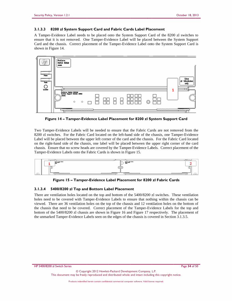
Security
HP 5400
3.1.3.
A TamensureCard ashown
Two T8200 zLabel on thechassiTampe
3.1.3.
There holes viewedthe chbottomthe un
y Policy, Version 1
0/8200 zl Switch S
This docum
3 8200 zl S
mper-Evidencee that it is not and the chassisn in Figure 14.
Figure 14 –
Tamper-Evidenzl switches. Fwill be placed
e right-hand sids. Ensure that er-Evidence La
Figure
4 5400/820
are ventilationneed to be covd. There are 3
hassis that needm of the 5400/nmarked Tampe
.2.1
Series
© Copyrment may be freely
Products indentified
System Supp
e Label needs removed. On
s. Correct pla
Tamper-Evid
nce Labels wilFor the Fabric d between the ude of the chasno screw head
abels onto the F
15 – Tamper
00 zl Top and
n holes locatedvered with Ta36 ventilation hd to be covere8200 zl chassier-Evidence La
right 2012 Hewlett reproduced and d
d herein contain confiden
port Card and
to be placed one Tamper-Evicement of the
dence Label
ll be needed toCard located o
upper left cornesis, one label
ds are covered Fabric Cards is
r-Evidence L
d Bottom La
d on the top anamper-Evidencholes on the toed. Correct pls are shown inabels seen on t
t-Packard Developdistributed whole
ntial commercial compu
d Fabric Card
onto the Systemidence Label wTamper-Evide
Placement f
o ensure that ton the left-haner of the card awill be placedby the Tampers shown in Fig
abel Placeme
bel Placeme
nd bottom of the Labels to en
op of the chasslacement of thn Figure 16 anhe edges of the
pment Company, L and intact includin
uter software. Valid licen
ds Label Plac
m Support Cawill be placedence Label ont
for 8200 zl Sy
the Fabric Carnd side of the cand the chassis
d between the ur-Evidence Lab
gure 15.
ent for 8200
nt
he 5400/8200 znsure that nothsis and 12 venthe Tamper-Evind Figure 17 ree chassis is cov
L.P. ng this copyright n
nse required.
cement
ard of the 8200d between the to the System
ystem Suppo
rds are not remchassis, one Tas. For the Fabupper right cobels. Correct p
zl Fabric Ca
zl switches. Thing within thetilation holes oidence Labels espectively. Thvered in Sectio
October 18, 20
Page 34 of 5
notice.
0 zl switches System SuppoSupport Card
ort Card
moved from thamper-Evidenc
bric Card locateorner of the carplacement of th
ards
These ventilatioe chassis can bon the bottom o
for the top anhe placement o
on 3.1.3.5.
013
50
to ort is
he ce ed rd he
on be of nd of

Security Policy, Version 1.2.1 October 18, 2013
HP 5400/8200 zl Switch Series Page 35 of 50
© Copyright 2012 Hewlett-Packard Development Company, L.P. This document may be freely reproduced and distributed whole and intact including this copyright notice.
Products indentified herein contain confidential commercial computer software. Valid license required.
Figure 16 – 5400/8200 zl Top Tamper-Evidence Label Placement

Security Policy, Version 1.2.1 October 18, 2013
HP 5400/8200 zl Switch Series Page 36 of 50
© Copyright 2012 Hewlett-Packard Development Company, L.P. This document may be freely reproduced and distributed whole and intact including this copyright notice.
Products indentified herein contain confidential commercial computer software. Valid license required.
Figure 17 – 5400/8200 zl Bottom Tamper-Evidence Label Placement
3.1.3.5 5400/8200 zl Sides Label Placement
Once the opacity shields have been securely installed onto the 5400/8200 zl Switch Series chassis, Tamper-Evidence Labels must be placed between the shields and the chassis to ensure that they cannot be removed. For the 5406 zl and 8206 zl chassis, two labels will be placed between the opacity shield and the rack mounting bracket. For the 5412 zl and 8212 zl chassis, three labels will be placed in the same location. Two more labels will be placed between the rack mounting bracket and the chassis to ensure the bracket cannot be removed. For all switches, labels will then be placed 3 along the top and 3 along the bottom, wrapping around and fastening to the top or bottom. Finally, labels will be placed along the rear of the opacity shield, securing it against the chassis. In this location, one label will be used for the 5406 zl switch, two labels for the 5412 zl and 8206 zl switch, and three labels for the 8212 zl switch. Repeat these steps for both sides of the module. The total number of Tamper-Evidence Labels needed for each side of the 5400/8200 zl Switch Series modules is as follows:
HP 5406 zl Switch: 11 Tamper-Evidence Labels HP 5412 zl Switch: 13 Tamper-Evidence Labels HP 8206 zl Switch: 12 Tamper-Evidence Labels HP 8212 zl Switch: 14 Tamper-Evidence Labels

Security Policy, Version 1.2.1 October 18, 2013
HP 5400/8200 zl Switch Series Page 37 of 50
© Copyright 2012 Hewlett-Packard Development Company, L.P. This document may be freely reproduced and distributed whole and intact including this copyright notice.
Products indentified herein contain confidential commercial computer software. Valid license required.
Correct placement of the Tamper-Evidence Labels on one side of the 5406 and 8206 switches is shown in Figure 18 and Figure 19 respectively. The unmarked label located at the rear of the chassis is wrapped around the fan tray. This placement is covered in Section 3.1.3.6.
Figure 18 – 5406 Side Tamper-Evidence Label Placement
Figure 19 – 8206 Side Tamper-Evidence Label Placement
Correct placement of the Tamper-Evidence Labels on one side of the 5412 and 8212 switches is shown in Figure 20 and Figure 21 respectively. The unmarked label located at the rear of the chassis is wrapped around the fan tray. This placement is covered in Section 3.1.3.6.

Security Policy, Version 1.2.1 October 18, 2013
HP 5400/8200 zl Switch Series Page 38 of 50
© Copyright 2012 Hewlett-Packard Development Company, L.P. This document may be freely reproduced and distributed whole and intact including this copyright notice.
Products indentified herein contain confidential commercial computer software. Valid license required.
Figure 20 – 5412 Side Tamper-Evidence Label Placement
Figure 21 – 8212 Side Tamper-Evidence Label Placement

Security Policy, Version 1.2.1 October 18, 2013
HP 5400/8200 zl Switch Series Page 39 of 50
© Copyright 2012 Hewlett-Packard Development Company, L.P. This document may be freely reproduced and distributed whole and intact including this copyright notice.
Products indentified herein contain confidential commercial computer software. Valid license required.
3.1.3.6 5400/8200 zl Rear Label Placement
Tamper-Evidence Labels are placed on the rear of the 5400/8200 zl Switch Series chassis to secure the removable power supplies and removable fan tray. For the 5406 and 8206 zl appliances, one label will be placed between each power supply and the chassis. A second Tamper-Evidence Label will be placed between the removable fan tray and the chassis; which must be wrapped around the side of the chassis. A third label will be placed between the top of the PSU blank plate and the chassis and a fourth will be placed between the bottom of the PSU blank plate and the chassis. Correct placement of the Tamper-Evidence Labels onto the power supplies or PSU blank plate of the 5406 zl or 8206 zl switch is shown in Figure 22 and Figure 23 respectively.
Figure 22 – 5406zl Rear Tamper-Evidence Label Placement
Figure 23 – 8206 zl Rear Tamper-Evidence Label Placement
The rear of the 5412 zl and 8212 zl switches require seven total Tamper-Evidence Labels. Two Tamper-Evidence Labels will be placed between each power supply and the chassis. For the power supply located on the bottom right of the chassis, one Tamper-Evidence Label will be placed between the top right corner of the power supply and the chassis. For the power supply located on the bottom left of the chassis, one

Security Policy, Version 1.2.1 October 18, 2013
HP 5400/8200 zl Switch Series Page 40 of 50
© Copyright 2012 Hewlett-Packard Development Company, L.P. This document may be freely reproduced and distributed whole and intact including this copyright notice.
Products indentified herein contain confidential commercial computer software. Valid license required.
Tamper-Evidence Label will be placed between the bottom left corner of the power supply and the chassis. The PSU blank plates require two labels each; one Tamper-Evidence Label placed between the top of the cover and the chassis and one between the bottom of the cover and the chassis. One Tamper-Evidence Label will be placed between the removable fan tray and the chassis, wrapped around the side of the chassis. Correct placement of the Tamper-Evidence Labels onto the power supplies or PSU blank plates of the 5412 zl or 8212 zl switch is shown in Figure 24 and Figure 25 respectively.
Figure 24 – 5412 zl Rear Tamper-Evidence Label Placement
Security Policy, Version 1.2.1 October 18, 2013
HP 5400/8200 zl Switch Series Page 41 of 50
© Copyright 2012 Hewlett-Packard Development Company, L.P. This document may be freely reproduced and distributed whole and intact including this copyright notice.
Products indentified herein contain confidential commercial computer software. Valid license required.
Figure 25 – 8212 zl Rear Tamper-Evidence Label Placement
3.2 Initialization of FIPS Mode The 5400/8200 zl switches are capable of two different modes of operation. Standard Secure-Mode is the non-FIPS Approved mode of operation for the switches. The FIPS-Approved mode of operation for the switches is referred to as Enhanced Secure-Mode. In this mode of operation, services such as Telnet, TFTP35, HTTP36, and SNMPv2 have to be disabled. Auxiliary ports and buttons capable of manual reset and password clearing need to be disabled on the front panel of the modules. Other services in the modules need to be enabled, such as SSH v2, SFTP and SNMPv3. The following initialization steps in this policy must be followed to ensure that the 5400/8200 zl switches are running in a FIPS-Approved mode of operation. For more information on switch software commands related to Secure Mode, see the chapter titled “Secure Mode (5400zl and 8200zl Switches)” in version K.15.07 or later in the Access Security Guide for your switch. Note: The FIPS set-up instructions here-in are to be executed from the local serial port of the switch. Note: The examples show a “HP-E8212zl#” prompt. Prompts will differ based on the specific switch model number.
35 TFTP – Trivial File Transfer Protocol 36 HTTP – Hypertext Transfer Protocol

Security Policy, Version 1.2.1 October 18, 2013
HP 5400/8200 zl Switch Series Page 42 of 50
© Copyright 2012 Hewlett-Packard Development Company, L.P. This document may be freely reproduced and distributed whole and intact including this copyright notice.
Products indentified herein contain confidential commercial computer software. Valid license required.
3.2.1 Pre-Initialization Prior to enabling the switch for a FIPS-Approved mode of operation, the CO must download the latest FIPS-Approved firmware image from HP and load it onto the switch. In the following example, the FIPS firmware image is downloaded as the primary flash image using this command structure: Copy tftp flash <tftp server> <FIPS image>
HP-E8212zl# copy tftp flash 192.168.1.1 K_15_07_0002.swi Once the image has been downloaded, the CO must reboot the switch (still in Standard Secure-Mode) with the newly loaded FIPS-Approved firmware image.
HP-E8212zl# boot system flash primary The switch will reboot to the primary flash image. Once presented with the CLI, the CO must download the FIPS-Approved image a second time. This is a mandatory measure to ensure that a FIPS-Approved image is being downloaded appropriately. Again, the FIPS firmware image will be downloaded as the primary flash image:
HP-E8212zl# copy tftp flash 192.168.1.1 K_15_07_0002.swi After completing the download, the CO will set the configuration file of the switch to its default settings. This will erase custom keys and other custom configuration settings.
HP-E8212zl# erase startup-config After the startup configuration file has been set to its default settings, the CO will enter the ‘configuration’ context and reboot the switch into a FIPS-ready mode of operation. This means that only FIPS-Approved algorithms and operations are used. Authentication, CSPs, and other services still need to be set up to bring the switch to a FIPS-Approved mode of operation.
HP-E8212zl# configure HP-E8212zl(config)# secure-mode enhanced
Before transitioning to Enhanced Secure-Mode, the CO will be asked to confirm whether or not they would like to zeroize the switch, erasing all Management Card files except for the firmware image. Zeroization is required when bringing the switch out of or into a FIPS-Approved mode of operation. This is required so that private keys and CSPs established in one mode of operation cannot be used in another. Zeroization can take up to an hour to complete.
The system will be rebooted and all Management Module files except software images will be erased and zeroized. This will take up to 60 minutes and the switch will not be usable during that time. Continue (y/n)?
After the CO confirms the above message, the switch will reboot directly into the last loaded firmware image (the FIPS firmware image), run cryptographic self-tests, and do complete zeroization of the switch. Once completed, the switch is ready to be configured to run in a FIPS-Approved mode of operation.
ATTENTION: Zeroization has started and will take up to 60 minutes. Interrupting this process may cause the switch to become unusable. Backing up firmware images and other system files... Zeroizing the file system... 100% Verifying cleanness of the file system... 100%

Security Policy, Version 1.2.1 October 18, 2013
HP 5400/8200 zl Switch Series Page 43 of 50
© Copyright 2012 Hewlett-Packard Development Company, L.P. This document may be freely reproduced and distributed whole and intact including this copyright notice.
Products indentified herein contain confidential commercial computer software. Valid license required.
Restoring firmware images and other system files... Zeroization of the file system completed. Continue initializing..initialization done.
3.2.2 Initialization and Configuration The steps outlined in this section will require the Cryptographic Officer to enter the ‘configuration’ context in order to execute the commands necessary for initializing the 5400/8200 zl Switch Series modules.
HP-E8212zl# configure
*E8200 zl Switches Only* The CO must set the redundancy mode of the two Management Cards to “Nonstop-Switching”. This will set the inactive Management Card to “Standby Mode” and will start synchronizing the stored images and all subsequent configuration steps with the currently operating Management Card (Active Management Card). If the Active Management Card fails, the Standby Management Card will be able to take over operation of the switch, eliminating the need to reboot the switch. The 5400 zl switches contain only one Management Card, therefore this operation is unavailable to them.
HP-E8212zl(config)# redundancy management-switch nonstop-switching The CO must create passwords for himself or herself, the User, and for the BootROM console in order to meet the security requirements laid out by FIPS PUB 140-2. All other commands for password management not used in this document are prohibited in the FIPS-Approved mode of operation. Password set-up must follow the authentication strength requirements set forth in section 2.4.3.2 (Authentication Mechanism Strength) of this document. A password for the BootROM console is necessary to ensure that only an authorized operator is able to access the BootROM console services. The CO shall be the only one with knowledge of the BootROM password.
HP-E8212zl(config)# password operator New password for operator: ******
Please retype new password for operator: ****** HP-E8212zl(config)# password manager New password for manager: ******* Please retype new password for manager: ******* HP-E8212zl(config)# password rom-console
Enter password: ******* Re-enter password: *******
Following password initialization, the CO will disable Telnet services.
HP-E8212zl(config)# no telnet-server
SSH v2 services will be turned on to allow the User and CO to access the switch’s CLI services remotely. To do this, the CO must first generate a new RSA key pair to be used for secure key and message transportation though the SSH v2 connection.
HP-E8212zl(config)# crypto key generate ssh rsa bits 3072 Installing new key pair. If the key/entropy cache is depleted, this could take up to a minute.
The follow command enables the SSH v2 server:
HP-E8212zl(config)# ip ssh

Security Policy, Version 1.2.1 October 18, 2013
HP 5400/8200 zl Switch Series Page 44 of 50
© Copyright 2012 Hewlett-Packard Development Company, L.P. This document may be freely reproduced and distributed whole and intact including this copyright notice.
Products indentified herein contain confidential commercial computer software. Valid license required.
SFTP/SCP services must be enabled in order to download new firmware images and security updates from HP Networking. It may also be necessary to access an SFTP server to save a copy of the configuration file or device log to an external storage device securely. Enabling SFTP will disable the TFTP service.
HP-E8212zl(config)# ip ssh filetransfer Tftp and auto-tftp have been disabled.
As an added security measure, the CO will type the following commands to ensure the switch does not have access to the TFTP client and server services:
HP-E8212zl(config)# no tftp client HP-E8212zl(config)# no tftp server
In order to disable SNMPv1 and SNMPv2, the CO must first initialize SNMPv3. Set-up of SNMPv3 requires that an initial user be created with an associated MD5 authentication hash. After creating the ‘initial’ user, the CO will type in an authentication password and associated privacy password for the ‘initial’ user:
HP-E8212zl(config)# snmpv3 enable SNMPv3 Initialization process. Creating user 'initial' Authentication Protocol: MD5 Enter authentication password: ******* Privacy protocol is DES Enter privacy password: *******
Following the creation of the ‘initial’ user, the CO will be asked if they would like to create a second user that uses SHA-1 for authentication. The CO will type ‘y’ then press the “Enter” or “Return” key in order to create the second user.
User 'initial' has been created Would you like to create a user that uses SHA? [y/n] y
Enter user name: crypto_officer Authentication Protocol: SHA Enter authentication password: ************** Privacy protocol is DES Enter privacy password: **************
Once the FIPS-Approved user has been created with their associated authentication and privacy passwords, the CO will limit access to SNMPv1 and SNMPv2c messages to ‘read only’. This does not disable SNMPv1 and SNMPv2.
User creation is done. SNMPv3 is now functional. Would you like to restrict SNMPv1 and SNMPv2c messages to have read only access (you can set this later by the command 'snmp restrict-access')? [y/n] y
The privacy protocol for the SNMPv3 “crypto_officer” user must be changed from DES to AES-128. Use the following command to manually change the privacy protocol for the “crypto_officer” user. Substitute the “*” with a secure password.
HP-E8212zl(config)# snmpv3 user crypto_officer auth sha ****** priv aes ******

Security Policy, Version 1.2.1 October 18, 2013
HP 5400/8200 zl Switch Series Page 45 of 50
© Copyright 2012 Hewlett-Packard Development Company, L.P. This document may be freely reproduced and distributed whole and intact including this copyright notice.
Products indentified herein contain confidential commercial computer software. Valid license required.
The following commands will be typed by the CO in order to delete the unapproved SNMPv3 user (‘initial’) and to disable use of SNMPv1 and SNMPv2.
HP-E8212zl(config)# no snmpv3 user initial HP-E8212zl(config)# no snmp-server enable HP-E8212zl(config)# snmpv3 only
Plaintext connections to the switch are not allowed in a FIPS-Approved mode of operation and must be disabled with the following command:
HP-E8212zl(config)# no web-management plaintext
HTTPS37 access to the module must be disabled. The CO can use the following command to disable SSL38 v3.1/TLS39 1.0 web management services.
HP-E8212zl(config)# no web-management ssl
To prevent unintentional factory reset of the switch, the “Reset” button located on the Management Card of the 5400 zl switches and on the System Support Module of the 8200 zl switches must be disabled. The CO must confirm the prompt with a ‘y’ to complete the command.
HP-E8212zl(config)# no front-panel-security factory-reset **** CAUTION **** Disabling the factory reset option prevents switch configuation and passwords from being easily reset or recovered. Ensure that you are familiar with the front panel security options before proceeding. Continue with disabling the factory reset option[y/n]? y
To prevent unintentional password reset of the switch, the “Clear” button located on the Management Card of the 5400 zl switches and on the System Support Module of the 8200 zl switches must be disabled. The CO must confirm the prompt with a ‘y’ to complete the command.
HP-E8212zl(config)# no front-panel-security password-clear **** CAUTION ****
Disabling the clear button prevents switch passwords from being easily reset or recovered. Ensure that you are familiar with the front panel security options before proceeding. Continue with disabling the clear button [y/n]? y
The auxiliary port located on the Management Card must be disabled avoid any unauthorized modifications to the module and its operational environment. Please note: The autorun feature will not function when the USB port is disabled.
HP-E8212zl(config)# no usb-port The switch must be configured to set proper fan and over-temperature behavior while FIPS Opacity Shields are installed onto the chassis. The following command will adjust the fan speed and “over temperature” behavior:
37 HTTPS – Secure Hypertext Transfer Protocol 38 SSL – Secure Socket Layer 39 TLS – Transport Layer Security

Security Policy, Version 1.2.1 October 18, 2013
HP 5400/8200 zl Switch Series Page 46 of 50
© Copyright 2012 Hewlett-Packard Development Company, L.P. This document may be freely reproduced and distributed whole and intact including this copyright notice.
Products indentified herein contain confidential commercial computer software. Valid license required.
HP-E8212zl(config)# opacity-shields
The start-up configuration file needs to be written with the new settings that have been applied in this section. The following command will write the new start-up configuration file: HP-E8212zl(config)# write memory The last steps to ensure that the switch is running in a FIPS-Approved mode of operation is to set the default boot image to the primary image and then reboot the switch into the newly configured FIPS-Approved firmware image.
HP-E8212zl(config)# boot set default primary HP-E8212zl(config)# boot system flash primary
3.2.3 Zeroization Zeroization is required when bringing the switch out of or into a FIPS-Approved mode of operation. This is required so that private keys and CSPs established in one mode of operation cannot be used in another. The 5400/8200 zl switches will execute full system zeroization when the switch is changing secure-mode states. For example, this can be done by calling secure-mode enhanced while the switch is in a “secure-mode standard” state. The module will not execute zeroization if calling secure-mode enhanced while the switch is currently in the “secure-mode enhanced” state. Zeroization can also be done by executing the erase all zeroize command. This command has the same effect as the above commands; however the switch will not transition to the opposite mode from which the command was called in. These commands shall only be called when accessing the switch directly through a serial connection. Otherwise status information about the zeroization process will not be displayed nor will the operator be able to access the module remotely until remote access has been set up. The only things that will remain on the switch after zeroization has completed are the BootROM image and the firmware images.
3.3 Secure Management Once the 5400/8200 zl switches have been configured for a FIPS-Approved mode of operation, the Crypto Officer will be responsible for keeping track of and regenerating RSA key pairs for SSH v2 authentication to the switches. Remote management is available via SSH v2. The CO is the only operator that can change configuration settings of the switch, which includes access control, password management, and port security. Physical access to and local control of the 5400/8200 zl switches shall be limited to the Cryptographic Officer.
3.4 User Guidance The user is only able to access the 5400/8200 zl switches remotely via SSH v2. When accessing the switches remotely via SSH v2, the User will be presented with the same CLI interface as if connected locally. In an SSH v2 session, the user is able to see most of the health information and configuration settings of the switches, but is unable to change them.
3.5 BootROM Guidance The primary purpose of the BootROM console is to download a new firmware image should there be a problem booting the current FIPS-Approved image. The BootROM may be accessed when rebooting the 5400/8200 zl switches locally through the serial port. When entering into the BootROM, the BootROM
Security Policy, Version 1.2.1 October 18, 2013
HP 5400/8200 zl Switch Series Page 47 of 50
© Copyright 2012 Hewlett-Packard Development Company, L.P. This document may be freely reproduced and distributed whole and intact including this copyright notice.
Products indentified herein contain confidential commercial computer software. Valid license required.
selection menu will present the CO with three options. Option 0 allows the CO to access BootROM console services. Option 1 and Option 2 allow the CO to boot the system into either the primary or secondary firmware image, respectively. Only a FIPS approved firmware image may be selected from the menu. If nothing is pressed within 3 seconds of being presented with the selection menu, the switch will boot into the last booted image. When accessing the BootROM console from the BootROM selection menu, the CO will be prompted for the BootROM password which was previously configured by the CO during switch initialization. This password shall be different than the CO password. A limited set of commands is available to the Crypto Officer within the BootROM console that allows the CO to download a new image, reboot the switch, zeroize the switch, or display BootROM image versioning information. The BootROM console may be exited at any time, to access the image selection menu, via the quit command.
3.6 Product Documentation For more information on switch software commands related to Secure Mode, see the chapter titled “Secure Mode (5400zl and 8200zl Switches)” in version K.15.07 or later in the Access Security Guide for your switch.
Security Policy, Version 1.2.1 October 18, 2013
HP 5400/8200 zl Switch Series Page 48 of 50
© Copyright 2012 Hewlett-Packard Development Company, L.P. This document may be freely reproduced and distributed whole and intact including this copyright notice.
Products indentified herein contain confidential commercial computer software. Valid license required.
4 Acronyms Table 12 describes the acronyms used throughout this document.
Table 12 – Acronyms
Acronym Definition
AC Alternating Current
AES Advanced Encryption Standard
ANSI American National Standards Institute
API Application Programming Interface
CBC Cipher Block Chaining
CFB Cipher Feedback Chaining
CMVP Cryptographic Module Validation Program
CPU Central Processing Unit
CSEC Communications Security Establishment Canada
CSP Critical Security Parameter
CTR Counter
DES Data Encryption Standard
DSA Digital Signature Algorithm
ECB Electronic Code Book
EMC Electromagnetic Compatibility
EMI Electromagnetic Interference
FIPS Federal Information Processing Standard
GbE Gigabit Ethernet
HMAC (keyed-) Hash Message Authentication Code
HTTP Hypertext Transfer Protocol
HTTPS Secure Hypertext Transfer Protocol
KAT Known Answer Test
KO Keying Option
LAN Local Area Network
LED Light Emitting Diode
NIST National Institute of Standards and Technology
NVLAP National Voluntary Laboratory Accreditation Program
OSPF Open Shortest Path First
PKCS Public Key Cryptography Standard

Security Policy, Version 1.2.1 October 18, 2013
HP 5400/8200 zl Switch Series Page 49 of 50
© Copyright 2012 Hewlett-Packard Development Company, L.P. This document may be freely reproduced and distributed whole and intact including this copyright notice.
Products indentified herein contain confidential commercial computer software. Valid license required.
Acronym Definition
PoE Power over Ethernet
PSU Power Supply Unit
RADIUS Remote Access Dial-In User Service
RIP Routing Information Protocol
RJ Registered Jack
RNG Random Number Generator
ROM Read Only Memory
RS Recommended Standard
RSA Rivest Shamir and Adleman
SFP Small Form-factor Pluggable
SHA Secure Hash Algorithm
SNMP Secure Network Management Protocol
SNTP Simple Network Transfer Protocol
SSH Secure Shell
SSL Secure Socket Layer
TACACS Terminal Access Controller Access-Control System
TLS Transport Layer Security
TFTP Trivial File Transfer Protocol
USB Universal Serial Bus
VLAN Virtual Local Area Network
VRRP Virtual Router Redundancy Protocol

C
13135 Le
U
PhEh
PrepCorsec S
ee JacksoSu
FairfaxUnited Sta
hone: +1 Email: infhttp://ww
pared bySecurity
on Memouite 220 x, VA 22ates of A
(703) [email protected]
y: y, Inc.
orial Hig 2033 America
67-6050 ec.com ec.com
ghway