1khf334933 - ahs-ps32-1402-b - sas functional description for ccr rev1
TRANSCRIPT

We reserve all rights in this document and in the information contained therein. Reproduction, use or disclosure to third parties without express authority is strictly forbidden. © Copyright 2013 ABB
台塑河靜鋼鐵興業責任有限公司
FORMOSA HA TINH STEEL CORPORATION
台灣化學纖維股份有限公司 工務部
FORMOSA CHEMICALS & FIBRE CORPORATION ENG. & UTILITY DIVISION
Document Code : AHS-PS32-1402-B CUSTOMER :
FORMOSA CHEMICALS & FIBRE CORP. PROJECT :
HA-THINH STEEL PLANT PROJECT – VIETNAM 220KV SUBSTATIONS
B 2013-07-04 SL SL SL
Rev Date Prepared / Revised
Checked Approved Note / Detail of Revision
Prepared :S.Lemmerann Based on : / Replaces :
AHS-PS32-1402-A
Sep.PL same No.
Without separ. PL
Scale : Doc.Type : Format :
Sep. PL anoth. No.
NA A4 Checked :S.Lemmermann Responsible department : PSSA-P Title :
SAS functional description for CCR
Approved : M.Günter Take over department : NA Language :
EN
�R
evis
ion
:
1 2013-07-04/SL No Sheets :
34
ABB Switzerland Ltd. Document Number : 1KHF334933
Sheet No :
1

© Copyright 2011 ABB. All rights reserved.
Customer doc. no. -
Based on - Customer FCFC Eng. & Utility Division Prepared Lemmermann 2012-01-07 Project Ha Thinh Steel Plant
Approved M.Günter 2012-01-07 Order 16234
Title SAS functional description for CCR
Ref. des. -
Resp. dept.
PSSA-P
Doc. no. Language Rev. Sheet 1
ABB Switzerland Ltd 1KHF334933 EN 1 No. sheets 33
Print: 4/07/2013 File: 1KHF334933 - AHS-PS32-1402-B - SAS functional description for CCR rev1.docm ; Rev. 1
Customer FCFC Eng. & Utility Division
Main contractor ABB CH - PSSS
Order 16234
Plant Ha Thinh Steel Plant - PPCCR
Equipment Substation Automation - mSCADA
Title SAS functional description for CCR

© Copyright 2011 ABB. All rights reserved. ABB 2012
Title
SAS functional description for CCR
Customer FCFC Eng. & Utility Division Project Ha Thinh Steel Plant Order 16234
Doc. no. Language Rev. Sheet 2
ABB Switzerland Ltd 1KHF334933 EN 1
No. sheets 33 Print: 4/07/2013 File: 1KHF334933 - AHS-PS32-1402-B - SAS functional description for CCR rev1.docm ; Rev. 1
Index
1. Preface ....................................................................................................................................... 3
1.1 Contents of this document .............................................................................................. 3 1.2 Target group of readers .................................................................................................. 3 1.3 Definitions and Abbreviations ......................................................................................... 3
2. Introduction ............................................................................................................................... 5
2.1 Scope of this document .................................................................................................. 5 2.2 Application Area ............................................................................................................. 5 2.3 System Description ......................................................................................................... 6
3. System Architecture ................................................................................................................. 8
3.1 System Hierarchy ........................................................................................................... 8 3.2 Communication system to PMS, EC and EVN Control Center (on hold by
customer) ...................................................................................................................... 11
4. Functional Description ........................................................................................................... 12
5. Hardware and Software Components ................................................................................... 13
5.1 Front End ...................................................................................................................... 13 5.2 Operator Workstation ................................................................................................... 15 5.3 Engineering Notebook .................................................................................................. 17 5.4 Training Workstation ..................................................................................................... 17 5.5 Simulation Workstation ................................................................................................. 18 5.6 Gateway ....................................................................................................................... 22 5.7 Video wall ..................................................................................................................... 23 5.8 Ethernet Switch ............................................................................................................ 23 5.9 Peripheral devices ........................................................................................................ 24
7. Appendix: Fiber Optic Cable Specification .......................................................................... 27
7.1 Fiber Optic Components ............................................................................................... 27 7.2 Standard Wavelengths ................................................................................................. 28 7.3 Fiber Optic Standards ................................................................................................... 28 7.4 Fiber Optic Cables inside cubicles ............................................................................... 29
8. Revision ................................................................................................................................... 33

© Copyright 2011 ABB. All rights reserved. ABB 2012
Title
SAS functional description for CCR
Customer FCFC Eng. & Utility Division Project Ha Thinh Steel Plant Order 16234
Doc. no. Language Rev. Sheet 3
ABB Switzerland Ltd 1KHF334933 EN 1
No. sheets 33 Print: 4/07/2013 File: 1KHF334933 - AHS-PS32-1402-B - SAS functional description for CCR rev1.docm ; Rev. 1
1. Preface
1.1 Contents of this document
The purpose of this Document is to describe the implemented functions of the SAS station mentioned in the first page of this document. All pictures and examples, which are shown, are of general manner, but cover all the needs.
1.2 Target group of readers
This functional description is intended for customer to see which functions are implemented in his SCMS system, where to find it and how to use it.
1.3 Definitions and Abbreviations
The following table is a list of abbreviations and acronyms used in this document. Product names are not taken into this list.
ACP Application Communication Protocol
CD-ROM Compact disk - read only memory
CE Certified standard: The device conforms to the directive 89/336/EWG on the approximation of the law of the member states of the European Community relating to electromagnetic compatibility.
COM Serial interface
CPU Central processor unit
DCS Digital Control System
DDE Dynamic Data Exchange
DOI Double Operating Interlock
FBS Fall-Back Switch
FUPLA Function Plan Programming Language for the ABB IEDs
GIS Gas Insulated Switchgear
GPS Global Positioning System
HSB Hot Stand-By
IED Intelligent Electronic Device
IP Ingress Protection standard IEC60529
ISA Industrial Standard Architecture
LDC Load Dispatch Centre
LAN Local Area Network
MicroSCADA Pro
Version of the base software, on which the SAS application is developed
HMI Man machine program for ABB IEDs
MMI
MMS Manufacturing Message SpecificationISO 9506-1 and ISO 9506-2
NCC Network Control Centre

© Copyright 2011 ABB. All rights reserved. ABB 2012
Title
SAS functional description for CCR
Customer FCFC Eng. & Utility Division Project Ha Thinh Steel Plant Order 16234
Doc. no. Language Rev. Sheet 4
ABB Switzerland Ltd 1KHF334933 EN 1
No. sheets 33 Print: 4/07/2013 File: 1KHF334933 - AHS-PS32-1402-B - SAS functional description for CCR rev1.docm ; Rev. 1
NIC Network Interface Card
NV Network Variable
ODBC Open Database Communication/Connectivity
OLE Object Linking and Embedding
OPC OLE for Process Control
PCMCIA Personal Computer Memory Card International Association
PC-NET Communication software for personal computers
RAM Random Access Memory
RAS Remote Access Service
RCC Remote Control Centre
RDBMS Relational Database Management System
RTU Remote Terminal Unit
SA Substation Automation
SAS Substation Automation System
SCIL Supervisory Control Implementation Language
SQL Structured Query Language
TCP/IP Transmission Control Protocol / Internet Protocol
TCS Tap change Control and Supervision
UPS Uninterruptible Power Supply
PPCCR Power Plant Control Center Room
© Copyright 2011 ABB. All rights reserved. ABB 2012
Title
SAS functional description for CCR
Customer FCFC Eng. & Utility Division Project Ha Thinh Steel Plant Order 16234
Doc. no. Language Rev. Sheet 5
ABB Switzerland Ltd 1KHF334933 EN 1
No. sheets 33 Print: 4/07/2013 File: 1KHF334933 - AHS-PS32-1402-B - SAS functional description for CCR rev1.docm ; Rev. 1
2. Introduction
2.1 Scope of this document
The Substation Automation System (SAS) functional description presents the design, functions, features and facilities of the SAS system.
This functional description is intended to provide an overview of the functions which are implemented in the SA system. For more detailed information and specifications, consult the Data Sheets of the relevant product. The software or hardware described in this document is furnished under a license and may be used, copied, or disclosed only in accordance with the terms of such license.
SAS built in PPCCR is a mirrored system of the 4 substations ESP01, ESP02, ESM01 and ESH01. Means that functionality will be same as in local Micro SCADA system Therefore this document will reference at several points to functional descriptions of local Micro SCADA at substations.
Project specific pictures will be submitted for approval at detail engineering phase for substations ESP01, ESP02, ESM01 and ESH01 as appendix.
2.2 Application Area
The substation automation system SAS600 Series is designed for controlling and monitoring the primary and secondary equipment of a substation. Typical applications are substations for power utilities on
distribution,
sub-transmission,
high-voltage transmission
extra high voltage transmission
new installations and refurbishment of existing substations
gas and air-insulated switchgear
The SAS600 series solutions for substation automation are based on and fully compliant with IEC61850. They provide the communication and integration of ABB's bay control and bay protection solutions (BCS6xx and BPS6xx), all the station level functions and as an option the remote link to e.g. a network control center.
The SAS provides an extensive range of Supervisory Control and Data Acquisition (SCADA) functions.
Control and supervision of switching devices, transformers, etc.
Bay and station interlocking
Current, voltage, frequency and power measurement
Alarm functions, storage and evaluation of events
Time synchronization of the system
User management
Disturbance recording and evaluation
Serial connection to all numerical relays

© Copyright 2011 ABB. All rights reserved. ABB 2012
Title
SAS functional description for CCR
Customer FCFC Eng. & Utility Division Project Ha Thinh Steel Plant Order 16234
Doc. no. Language Rev. Sheet 6
ABB Switzerland Ltd 1KHF334933 EN 1
No. sheets 33 Print: 4/07/2013 File: 1KHF334933 - AHS-PS32-1402-B - SAS functional description for CCR rev1.docm ; Rev. 1
2.3 System Description
The SAS600 series are state-of-the art solutions based on IEC61850 for operation under electrical conditions present in high-voltage substations, follow the latest engineering practice, ensure long-term compatibility requirements and continuity of equipment supply and the safety of the operating staff.
The system is designed in such a way that personnel without any background knowledge in microprocessor-based technology are able to operate the system easily after having received some basic training.
Cubicles that incorporate the control, monitoring and protection functions provide self-monitoring, signaling and testing facilities, measurement as well as memory functions, event recording and disturbance recording. The basic control functions are derived from a modular standardized and type-tested software library.
Maintenance, modification or extension of components does not cause a shut down of the whole substation automation system. Self-monitoring of single components, modules and communication is incorporated to increase the availability and the reliability of the system and minimize maintenance.
Protection and control devices are freely adaptable to the required application functionality.
The SAS conforms fully to the IEC61850 standard and has a decentralized architecture consisting of the following main hardware components:
Application server and Human Machine Interface (HMI)
Managed switched fiber-optic Ethernet LAN in a fault tolerant ring architecture
Gateway for remote communication to Remote Control Centre (RCC) and / or National control Center (NCC), communicating for example on IEC 60870-5-101 protocol
Dot matrix printer (DMP) for alarms and events
Laser printer for printing graphics and reports
GPS receiver per station to synchronize the time of SAS including the IEDs.
IEDs for bay and station protection
IEDs for bay control and monitoring
Disturbance Recorder (DR) evaluation workstation
Multi-Meters and energy meters for measurement report
The basic functions / features of a Substation Automation System are listed below:
Supervision and control of switching devices, transformers, tap changers and other controllable primary equipment
Local as well as remote control of the substation switching devices
Safety checks, station and bay interlocking
Time synchronization of the SA system
Current, voltage, frequency and power measurement
System supervision of the secondary and station level devices

© Copyright 2011 ABB. All rights reserved. ABB 2012
Title
SAS functional description for CCR
Customer FCFC Eng. & Utility Division Project Ha Thinh Steel Plant Order 16234
Doc. no. Language Rev. Sheet 7
ABB Switzerland Ltd 1KHF334933 EN 1
No. sheets 33 Print: 4/07/2013 File: 1KHF334933 - AHS-PS32-1402-B - SAS functional description for CCR rev1.docm ; Rev. 1
Alarm functions, storage and evaluation of events, blocking lists
Time scheduled activities
User management
Optional advanced functions provided in the SAS are:
Trend recording and storage
Measurement reports
IED parameterization
Disturbance recording, upload and analysis
Trip counter table
Dynamic busbar coloring
Perform auto electrical billing calculation
The above in this chapter describes in general the possible features of SAS600 series, which will be implemented in ESP01, ESP02, ESM01 and ESH01. SAS built in PPCCR is a mirrored system of the 4 substations. Means that functionality will be same as in local Micro SCADA system Therefore this document will reference at several points to functional descriptions of local Micro SCADA at substations.
© Copyright 2011 ABB. All rights reserved. ABB 2012
Title
SAS functional description for CCR
Customer FCFC Eng. & Utility Division Project Ha Thinh Steel Plant Order 16234
Doc. no. Language Rev. Sheet 8
ABB Switzerland Ltd 1KHF334933 EN 1
No. sheets 33 Print: 4/07/2013 File: 1KHF334933 - AHS-PS32-1402-B - SAS functional description for CCR rev1.docm ; Rev. 1
3. System Architecture
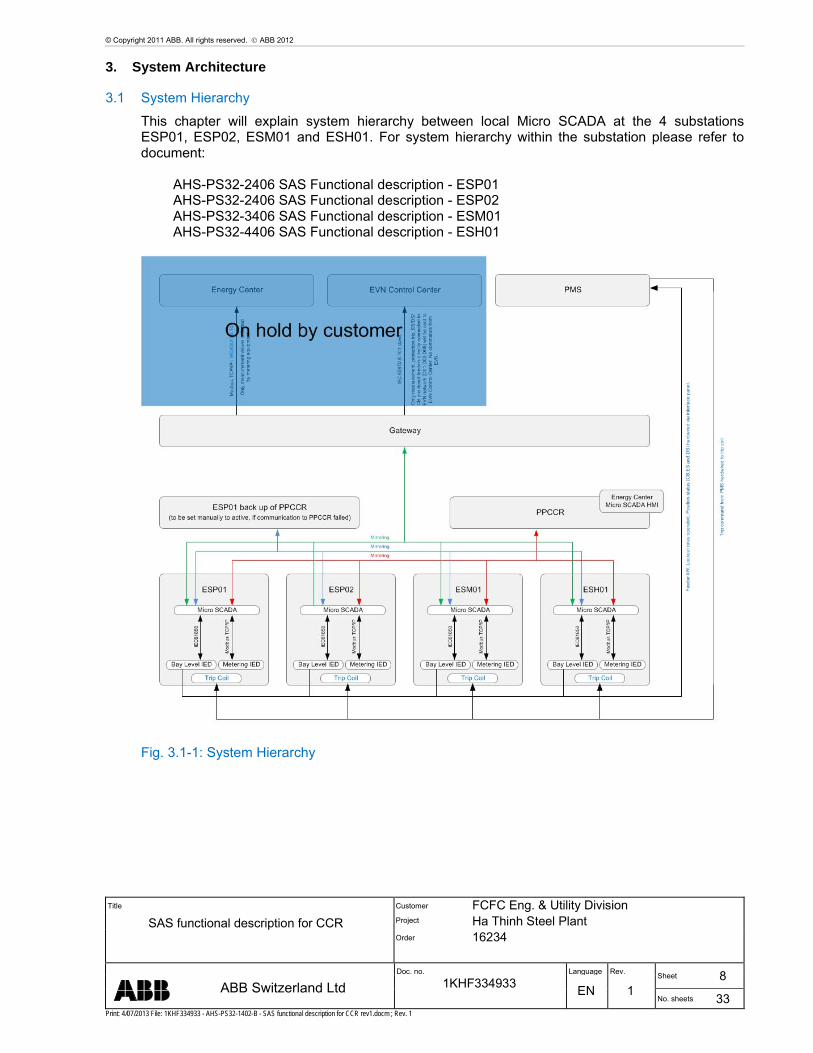
3.1 System Hierarchy
This chapter will explain system hierarchy between local Micro SCADA at the 4 substations ESP01, ESP02, ESM01 and ESH01. For system hierarchy within the substation please refer to document:
AHS-PS32-2406 SAS Functional description - ESP01 AHS-PS32-2406 SAS Functional description - ESP02 AHS-PS32-3406 SAS Functional description - ESM01 AHS-PS32-4406 SAS Functional description - ESH01
Fig. 3.1-1: System Hierarchy

© Copyright 2011 ABB. All rights reserved. ABB 2012
Title
SAS functional description for CCR
Customer FCFC Eng. & Utility Division Project Ha Thinh Steel Plant Order 16234
Doc. no. Language Rev. Sheet 9
ABB Switzerland Ltd 1KHF334933 EN 1
No. sheets 33 Print: 4/07/2013 File: 1KHF334933 - AHS-PS32-1402-B - SAS functional description for CCR rev1.docm ; Rev. 1
The system architecture of the PPCCR SAS as shown above (Fig. 3.1-1) is designed in a manner which facilitates different hierarchical levels:
EVN Control Center
PMS
Energy Center
PPCCR
ESP01 back up of PPCCR
Local Micro SCADA at Substations
These are described in detail below. Control and monitoring of all 4 substations is only possible in PPCCR and ESP01 back up of PPCCR. Monitoring function between substation will be realized via remote desktop application with Micro SCADA viewer access.
3.1.1 EVN Control Center
EVN Control Center A0 & A1 have only switching authority (in parallel) via gateway for CB, DS, ES HSES in AA2.D1. EVN Control Center A0 & A1 have only switching authority (in parallel) for CB, DS, ES HSES for generator feeder (D2.Q09, D2.Q11, D2.Q12, D2.Q19, D2.Q20) in AA2.D2. Following signals shall be provided for all feeders of AA2.D1 and AA2.D2
Measurement
o Busbar: kV, Hz
o Generator feeder: MW, Mvar, high-limit control (MW), low-limit control (MW)
o Transformer feeder (220/220kV & 220/35kV): MW, Mvar, kV, A
o Transmission line: Mw, Mvar, kV, A
o Power Plant total active power, total reactive power
Alarm signals
Control mode indication (station & bay level)
Tap Changer indication (tap, raise, lower, faulty)
Operation mode of IED (faulty, healthy, testmode)
Protection Trip & Alarm (Mechanical Protection & numerical protection)
ES/DS/CB position (double point)
Communication protocol is IEC 60870-5-101 slave.
3.1.2 Power Management System (PMS)
PMS requirements (only applicable for ESP01 and ESP02): Analogue signals from ESP01 & ESP02 to PMS system:
© Copyright 2011 ABB. All rights reserved. ABB 2012
Title
SAS functional description for CCR
Customer FCFC Eng. & Utility Division Project Ha Thinh Steel Plant Order 16234
Doc. no. Language Rev. Sheet 10
ABB Switzerland Ltd 1KHF334933 EN 1
No. sheets 33 Print: 4/07/2013 File: 1KHF334933 - AHS-PS32-1402-B - SAS functional description for CCR rev1.docm ; Rev. 1
Feeder kW/T (via transducer 4 to 20mA) for all 220kV Feeder and 35kV outgoing feeder exclude capacitor.
Main bus (BB1A, BB1B, BB2A, BB2B of AA2.D2) frequency and voltage (via transducer 4 to 20mA)
Binary signals from ESP01 & ESP02 to PMS system: 220kV Lockout relay (86) operated (2 dry contact)
220kV and 35kV CB and DS status “On” and “Off” (1 dry contact per object/status)
Main bus (BB1A, BB1B, BB2A, BB2B of AA2.D2) 81U1 (1 dry trip contact), 81U2 (1 dry trip contact), 81O1 (1 dry trip contact), 27 (1 dry trip contact),
Binary signals from PMS System to ESP01 and ESP02:
Load shedding: 1 dry contact for tripping on TC1 and 1 dry contact for alarm to BCU/Micro SCADA) for =AA2.D2.Q21 =AA2.D2.Q22
Load shedding: 35kV Feeder (ESP01/ESP02): 1 dry contact for tripping on TC1 and 1 dry contact for alarm to BCU/Micro SCADA)
Dynamic breaking: 1 dry contact for tripping on TC1 and 1 dry contact for alarm to BCU/Micro SCADA) for =AA2.D2.D2.Q09, =AA2.D2.D2.Q11, =AA2.D2.D2.Q12, =AA2.D2.D2.Q19, =AA2.D2.D2.Q20
Signals shall be hardwired directly to PMS panel. No communication protocol provided. One spare LAN Card port (RJ45) will be reserved at Gateway 1 and Gateway 2.
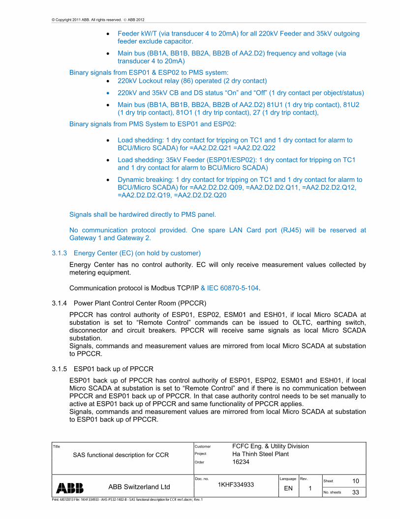
3.1.3 Energy Center (EC) (on hold by customer)
Energy Center has no control authority. EC will only receive measurement values collected by metering equipment. Communication protocol is Modbus TCP/IP & IEC 60870-5-104.
3.1.4 Power Plant Control Center Room (PPCCR)
PPCCR has control authority of ESP01, ESP02, ESM01 and ESH01, if local Micro SCADA at substation is set to “Remote Control” commands can be issued to OLTC, earthing switch, disconnector and circuit breakers. PPCCR will receive same signals as local Micro SCADA substation. Signals, commands and measurement values are mirrored from local Micro SCADA at substation to PPCCR.
3.1.5 ESP01 back up of PPCCR
ESP01 back up of PPCCR has control authority of ESP01, ESP02, ESM01 and ESH01, if local Micro SCADA at substation is set to “Remote Control” and if there is no communication between PPCCR and ESP01 back up of PPCCR. In that case authority control needs to be set manually to active at ESP01 back up of PPCCR and same functionality of PPCCR applies. Signals, commands and measurement values are mirrored from local Micro SCADA at substation to ESP01 back up of PPCCR.

© Copyright 2011 ABB. All rights reserved. ABB 2012
Title
SAS functional description for CCR
Customer FCFC Eng. & Utility Division Project Ha Thinh Steel Plant Order 16234
Doc. no. Language Rev. Sheet 11
ABB Switzerland Ltd 1KHF334933 EN 1
No. sheets 33 Print: 4/07/2013 File: 1KHF334933 - AHS-PS32-1402-B - SAS functional description for CCR rev1.docm ; Rev. 1
3.2 Communication system to PMS, EC and EVN Control Center (on hold by customer)
This is a communication software package / HW providing gateway services for routing the data flow between the process and network control systems. The data transfer usually involves protocol conversion. It also handles system coordination tasks, such as dynamic assignments of the control command authorities. A variety of protocols for connecting upper level systems are supported. For EC Modbus TCP/IP and for EVN Control Center IEC 60870-5-101 slave is assigned.
3.2.1 Station Level
The components at PPCCR are Front End Computers, Workstations, Gateways, printers, master clock for synchronization and video wall system. These are connected together via an Ethernet LAN utilizing the TCP/IP protocol. A dedicated GPS master clock is provided for the synchronization of the entire system. This master clock is independent of the station computers and gateways, and it synchronizes all devices via the station bus. The communication gateway enables communication to the next higher level system, for data and information exchange with PMS, EC and EVN Control Center. In order to increase the reliability, local Hot-Standby workstation located in ESP01 is dedicated as backup system of main control system in CCR. Additional an engineering workstation laptop including docking station is foreseen, which can be used at PPCCR or any of the 4 substations for engineering work. Laptop needs to be connected to certain station or bay level LAN switches (or directly to IED) for engineering and maintenance work.
3.2.2 Station Level LAN
The Ethernet based on IEEE 802.3 (CSMA/ CD) and OSI TCP/IP is used to interconnect the subsystems (ESP01, ESP02, ESM01, ESH01) of superior system at PPCCR. Front End computer, workstations, communication units (routers, repeaters) and print servers are connected to the local area network (LAN) with a communication speed of 100 or 1000Mbit/s depending on the device speed.

© Copyright 2011 ABB. All rights reserved. ABB 2012
Title
SAS functional description for CCR
Customer FCFC Eng. & Utility Division Project Ha Thinh Steel Plant Order 16234
Doc. no. Language Rev. Sheet 12
ABB Switzerland Ltd 1KHF334933 EN 1
No. sheets 33 Print: 4/07/2013 File: 1KHF334933 - AHS-PS32-1402-B - SAS functional description for CCR rev1.docm ; Rev. 1
4. Functional Description
Micro SCADA in PPCCR is only a mirrored application of local Micro SCADA systems of substations ESP01, ESP02, ESM01 and ESH01. Therefore, please refer to documents:
AHS-PS32-2406 SAS Functional description - ESP01 AHS-PS32-2406 SAS Functional description - ESP02 AHS-PS32-3406 SAS Functional description - ESM01 AHS-PS32-4406 SAS Functional description - ESH01
for detailed information of following topics: System Overview
Software Description Process Database
Overview Process object function Process object types Data processing Report Database System objects Base tools
Application Engineering System Functions
Station HMI Login and User Management Monitor Layout
Time Synchronization Control Authority handling
Station Local/Remote control Bay Local/Remote control
Basic Monitoring and Control Functions Colors and Symbols
Busbar and line colors Symbol Colors Symbols for Switching Objects
Process Displays Level Level 1: Overall Single Line Picture Level 2: Single Line Picture Level 3: Bay View Picture
System Self Supervision Event List Alarm List Blocking List Control Concept
Select before operate Synchrocheck bypass and interlocking bypass Measurement presentation
Advanced Monitoring and Control Functions Trends and Process Value Measurements Parameter setting in IED’s Busbar Coloring

© Copyright 2011 ABB. All rights reserved. ABB 2012
Title
SAS functional description for CCR
Customer FCFC Eng. & Utility Division Project Ha Thinh Steel Plant Order 16234
Doc. no. Language Rev. Sheet 13
ABB Switzerland Ltd 1KHF334933 EN 1
No. sheets 33 Print: 4/07/2013 File: 1KHF334933 - AHS-PS32-1402-B - SAS functional description for CCR rev1.docm ; Rev. 1
5. Hardware and Software Components
5.1 Front End
5.1.1 Redundant Station Computer
The redundant station computers contain the supervisory and control functions. The station computers are high-profile pre-tested industrial PCs running under the Windows 2003 operating system and the MicroSCADA application software. The redundant station computers work in a hot standby configuration. During normal operation, the standby station computer mainly works as a second workplace. The mutual supervision of the station computers and the database shadowing is performed via the redundant station LAN. In the event that the hot station computer fails, the standby station computer takes over the process control immediately. Getting all actual process data at any time via the IEC61850 bus supports the actuality of data. Also manual changes in the database of the hot station computer, e.g. pictures or limit values, are automatically copied to the standby station computer. In order to communicate with the IEDs using the IEC61850 protocol for each bus segment, one LAN card in each station computer is required. The redundant station computers also serve as redundant operator/engineering workstations.
5.1.2 Hot standby Station Computer
The two Front End computer base systems are working in a hot standby configuration. The hot system performs the communication tasks to the process and to the printer.
The hot standby concept is based on data shadowing of disk-resident data as well as RAM-resident data between the two base systems. The entity subject to shadowing is the application of Micro SCADA. In case of
Failure of the hot station computer
Failure of the hot application
Failure of the communication between the hot and stand-by PC
Failure of communication between hot station computer and local Micro SCADA at ESP01, ESP02, ESM01 and ESH01
a take-over will take place meaning that the application receiving the shadowed data in stand-by mode will become hot and the application activities are started. The stand-by application is an identical copy of the hot application both in respect of disk data and in respect of RAM-resident data. Data is shadowed on event basis, i.e. during the run-time only changed data items are shadowed. Temporary disk and RAM resident-data such as picture and report caches, printer spools, execution states and monitor states are not shadowed. At start-up, a complete copy is made from the hot application to the stand-by application. The shadowing is fully symmetric meaning that the application may be shadowed in both directions in turn. Take-over may also be initiated manually. After a take-over, the shadowing will automatically start in the reversed direction when the system detects that the failed station computer is available.
The interconnected station computers are connected with a TCP/IP link with a bit rate of 1000 Mbit/s.
5.1.3 System startup
The station computers are always running and it is usually not allowed to shut them down.
After a power loss they are starting up automatically:
Operating system Windows 2008 Server will start.
MicroSCADA and its applications will start.

© Copyright 2011 ABB. All rights reserved. ABB 2012
Title
SAS functional description for CCR
Customer FCFC Eng. & Utility Division Project Ha Thinh Steel Plant Order 16234
Doc. no. Language Rev. Sheet 14
ABB Switzerland Ltd 1KHF334933 EN 1
No. sheets 33 Print: 4/07/2013 File: 1KHF334933 - AHS-PS32-1402-B - SAS functional description for CCR rev1.docm ; Rev. 1
The station computer, which comes up first, will take over the hot state
The Terminal connections to the application data of the actual running hot station computer will be done and the operator will be asked for his MicroSCADA username and password.
The operator will only be able to operate from the SAS according his user authorization level.
5.1.4 Front End Software
Item Description Remark 1 Windows 2008 Server R2 64bit Base 2 Print Key Base 3 Internet Explorer Base 4 Adobe Reader Base 5 Obermeier Base 6 mSCADA Professional Base 7 Terminal server (open licence) Base
5.1.5 Front End Hardware
The Front-End computer is provided with monitor, keyboard and mouse. It is mainly used for operating of the SAS.
Item Description Detail 1 Industrial PC 19-inch slide-in 2 Housing 7-slot slide-in housing ATX for 19-inch
racks, 4 rack units 3 Slots all for full-length plug-in cards
3 PCI Express x1 3 PCI slots 1 PCI Express x16
4 Front flap Lockable 5 Card holders 6 Protection class IP60 when operating7 Operating temperature 0…55 °C 8 Weight of the basic
configuration 17.0 kg (37.5 lbs)
9 Dimensions 483 x 177 x 500 mm / 19" x 7" x 19.5" (W x H x D)
10 Processor
2nd Generation Intel® Core™ i7, 2.1 GHz, 4 cores (TC3: 80)
11 Motherboard ATX motherboard for 2nd Generation Intel® Core™ i3, Core™ i5, Core™ i7 or Celeron®
12 RAM 4 GB DDR3 RAM 13 Graphic adapter Integrated inside the Intel® processor: 1
DVI-I 1 DVI-D 1 Display Port connector 2 of 3 connectors useable at same time
14 Dual Ethernet adapter On-board with 2 x 10/100/1000BASE-T connector 1 Dual Port Gigabit-Ethernet-PC network cards, PCI-Express-x1-Bus
15 RAID on-board SATA RAID 1 controller, Intel® Rapid Storage Technology
16 Hard disk 1. 3½-inch, 500 GB

© Copyright 2011 ABB. All rights reserved. ABB 2012
Title
SAS functional description for CCR
Customer FCFC Eng. & Utility Division Project Ha Thinh Steel Plant Order 16234
Doc. no. Language Rev. Sheet 15
ABB Switzerland Ltd 1KHF334933 EN 1
No. sheets 33 Print: 4/07/2013 File: 1KHF334933 - AHS-PS32-1402-B - SAS functional description for CCR rev1.docm ; Rev. 1
2. 3½-inch, 320 GB 17 Serial ports 4xRS232 1 of these RS232 ports are led
out with 9-pin D-sub connectors; 14 USB 2.0, 4 of these USB ports are led out at the rear side and 2 are behind the front flap
18 Keyboard socket PS/2 19 Mouse socket PS/2 20 Power Supply Redundant
100–240 V AC (50/60Hz) full range power supply
5.2 Operator Workstation
The operator workstation is provided with monitor, keyboard and mouse. It is mainly used for operating of the SAS. The operator workstation knows, which station computer is the hot base system, and the data will be fetched from there. The process pictures shown on the operator workplace are stored in the front-end computers. The operator workstation calls the picture from the actual running hot base system.
5.2.1 Operator Workstation Software
Item Description Remark 1 Windows 7 Base 2 Print Key Base3 Internet Explorer Base4 Adobe Reader Base
5.2.2 Operator Workstation Hardware
Item Description Detail 1 Industrial PC 19-inch slide-in 2 Housing 7-slot slide-in housing ATX for 19-inch
racks, 4 rack units 3 Slots all for full-length plug-in cards
3 PCI Express x1 3 PCI slots 1 PCI Express x16
4 Front flap Lockable 5 Card holders 6 Protection class IP60 when operating 7 Operating temperature 0…55 °C 8 Weight of the basic
configuration 17.0 kg (37.5 lbs)
9 Dimensions 483 x 177 x 500 mm / 19" x 7" x 19.5" (W x H x D)
10 Processor Intel® Celeron® 1.6 GHz, 2 Core (TC3: 50) 11 Motherboard ATX motherboard for 2nd Generation Intel®
Core™ i3, Core™ i5, Core™ i7 or Celeron® 12 RAM 4 GB DDR3 RAM 13 Graphic adapter Integrated inside the Intel® processor: 1
DVI-I 1 DVI-D 1 Display Port connector 2 of 3 connectors useable at same time
14 Dual Ethernet adapter On-board with 2 x 10/100/1000BASE-T

© Copyright 2011 ABB. All rights reserved. ABB 2012
Title
SAS functional description for CCR
Customer FCFC Eng. & Utility Division Project Ha Thinh Steel Plant Order 16234
Doc. no. Language Rev. Sheet 16
ABB Switzerland Ltd 1KHF334933 EN 1
No. sheets 33 Print: 4/07/2013 File: 1KHF334933 - AHS-PS32-1402-B - SAS functional description for CCR rev1.docm ; Rev. 1
5.2:2 OWS installed in Front End Cubicle
Item Description Detail 1 Industrial PC ATX-Midi Tower 2 Processor IIntel® Core™2 Quad Processor Q9400
(6M Cache, 2.66 GHz, 1333 MHz FSB) 3 Motherboard Intel Q35 and ICH9 DO supporting
800/1066/1333 MHz FSB Supports dual core and quad core process with 45nm processing Dual channel DDR2 667/800 SDRAM up to 8 GB PCIe x 16 slot for external VGA card Supports 4 PCI and 2 PCIe x1 1 parallel (SPP/EPP/ECP) 2 PS/2 Supports 6 SATA II and software RAID 0, 1, 5, 10 Built in with dual GbE controllers support optional TPM module
4 RAM 4GB DDR2 800MHz RAM 5 Graphic adapter Chipset integrated VGA controller
6 LAN Card Network Card 1x 10/100-RJ45, 1x 100-ST,
PCI 7 DVD/CD Writer CD-DVD-RW Drive, 20X IDE
DVD+/-RW DL 8 Hard disk 500GB SATA Harddisk
3.5" SATA 7KRPM 9 Serial ports 4 USB 2.0 ports on rear
4 serial ports (3 of RS-232, 1 of RS-232/422/485)
10 Keyboard socket PS/2 11 Mouse socket PS/2 12 Power Supply 450W AC-DC ATX Power Supply
5.2:2 Desktop OWS
connector 1 Dual Port Gigabit-Ethernet-PC network cards, PCI-Express-x1-Bus
15 RAID on-board SATA RAID 1 controller, Intel® Rapid Storage Technology
16 Hard disk 3½-inch, 500 GB 17 Serial ports 4xRS232 1 of these RS232 ports are led
out with 9-pin D-sub connectors; 14 USB 2.0, 4 of these USB ports are led out at the rear side and 2 are behind the front flap
18 Keyboard socket PS/2 19 Mouse socket PS/220 Power Supply 100–240 V AC (50/60Hz) full range power
supply

© Copyright 2011 ABB. All rights reserved. ABB 2012
Title
SAS functional description for CCR
Customer FCFC Eng. & Utility Division Project Ha Thinh Steel Plant Order 16234
Doc. no. Language Rev. Sheet 17
ABB Switzerland Ltd 1KHF334933 EN 1
No. sheets 33 Print: 4/07/2013 File: 1KHF334933 - AHS-PS32-1402-B - SAS functional description for CCR rev1.docm ; Rev. 1
5.3 Engineering Notebook
The engineering notebook is provided with docking station, keyboard and mouse. It is mainly used for engineering of the SAS but could also be used in the same manner as the operator workstation. The engineering workstation knows, which front-end computer is the hot base system, and the data will be fetched from there. The process pictures shown on the engineering workplace are stored in the front-end computers. The engineering notebook calls the picture from the actual running hot base system.
5.3.1 Engineering Notebook Software
Item Description Remark 1 Windows 7 Base 2 Print key Base 3 Internet Explorer Base 4 Adobe Reader Base 5 Microsoft Office Professional
5.3.2 Engineering Notebook Hardware
5.4 Training Workstation
On a separate workstation as build mSCADA application will be installed. All data points will be set to “fictive”. Real time data update is not possible. With this training workstation the staff will be able to train the mSCADA handling. Commands can be issued and object feedback (open/close) will be simulated. Busbar coloring and event-list update is activated. Blocking and Interlocking conditions will not be realized.
Item Description Detail 1 Docking Station Sony VGP-PRS30 500 GB Hard disk 2 Laptop Sony SVS1313C5E
Processor Intel® CoreTM i7-3540M, 3 GHz
Keyboard US RAM 8 GB 1333 MHz DDR3L-
SDRAM Display 33.7cm LCD Resolution 1366x768 Intel® GPU Graphic card Intel HD Graphics 3000 Hard disk 500 GB Serial ATA (7200
U/Min)

© Copyright 2011 ABB. All rights reserved. ABB 2012
Title
SAS functional description for CCR
Customer FCFC Eng. & Utility Division Project Ha Thinh Steel Plant Order 16234
Doc. no. Language Rev. Sheet 18
ABB Switzerland Ltd 1KHF334933 EN 1
No. sheets 33 Print: 4/07/2013 File: 1KHF334933 - AHS-PS32-1402-B - SAS functional description for CCR rev1.docm ; Rev. 1
5.5 Simulation Workstation
5.5.1 Definition of the network size for licensing
Medium size Number of primary substations <15 Number of MV/LV subst.(load points) <1000 Number of switching devices <2000
5.5.2 Implemented functions
Base System (Topology Management)
Network Analysis
General Extensions
HSB support HSB support means that DMS 600 can always use the active MicroSCADA Pro SYS 600 server in SCADA interface. DMS 600 is using one MS SQL Server database and database servers are not redundant.
5.5.3 The substation parts/voltage levels that are connected to DMS 600 system:
220 kV network and outgoing 35 kV feeders to load points like e.g. 35/6 kV transformers. Totally 124 ( 32 + 60 + 32 ) outgoing feeders. Each feeder is having only one load point e.g. 35/6 kV transformer.

© Copyright 2011 ABB. All rights reserved. ABB 2012
Title
SAS functional description for CCR
Customer FCFC Eng. & Utility Division Project Ha Thinh Steel Plant Order 16234
Doc. no. Language Rev. Sheet 19
ABB Switzerland Ltd 1KHF334933 EN 1
No. sheets 33 Print: 4/07/2013 File: 1KHF334933 - AHS-PS32-1402-B - SAS functional description for CCR rev1.docm ; Rev. 1
5.5.4 Overview of Network Analysis
Network analysis functions offer load flow and fault current calculations and over-current protection analysis of radially operated and meshed networks. The generators are taken into account during the network analysis. Additionally, the distributed generators and capacitors are taken into account in the load flow calculations. The protection analysis function can analyze definite time-delay and inverse time type overcurrent relays. Also the medium voltage fuses are taken into account during protection analysis. The solid earthed networks and networks earthed via resistor are supported in the protection analysis. Network analysis is used to define the electrical state of the distribution network in a Real-time or simulated network topology using network calculations, i.e. the load flow and fault current calculations. Calculations can also use measurement data provided by MicroSCADA. Manually updateable measurements can be used to model the separate load point, load of border switch or backup feeder. Load estimation means the correction of the feeders and substations loads calculated using static load data such that the loads of the feeders approximate the current measurement of the feeder from MicroSCADA. The electrical state of the network can then be calculated as accurate as possible. The following network data is needed for calculation purposes during network analysis in WS: Distribution network data. 1. Electrical properties of conductors. 2. Switching state of the network. 3. Load data for load flow calculation. 4. Relay data for protection analysis. Load data is needed for the load flow calculation. Load data can be entered and edited by using the load info forms, which are available for MV/LV substations. Relay data is used in protection

© Copyright 2011 ABB. All rights reserved. ABB 2012
Title
SAS functional description for CCR
Customer FCFC Eng. & Utility Division Project Ha Thinh Steel Plant Order 16234
Doc. no. Language Rev. Sheet 20
ABB Switzerland Ltd 1KHF334933 EN 1
No. sheets 33 Print: 4/07/2013 File: 1KHF334933 - AHS-PS32-1402-B - SAS functional description for CCR rev1.docm ; Rev. 1
analysis. It can be changed via the circuit breaker data forms. Load and relay data is saved as a part of the network database. The electrical properties of conductors are also stored in the network database. During simulations in DMS 600 WS, the relay settings, load calculation methods, and network topology can be changed. The load forecasting starts automatically every hour. It creates dynamic load curves for feeders and provides also short-term (1 hour to 1 week) load forecasts for secondary substation loads. The calculation uses the latest MicroSCADA measurements). Additionally, Load Estimation using available hourly current or P and Q measurements from SCADA can be used to improve the network analysis accuracy and to form short-term forecasts for secondary substation loads for radial feeders. The network topology is automatically updated and networks analysis executed after every switching state change, if the feature is not disabled by settings. Network calculation results can be seen as color’s in the network window, reflecting voltage drops, detection ability for short-circuit, three-phase short-circuit capacity, detection ability of earth fault and load levels. The results are shown as selected in the viewing settings. Warning level and alarm level colors are used in presenting network analysis results when the calculated values exceed the corresponding settings for the limits. The representation of the calculation result depends on the user-defined settings. The switching state of a distribution network is changed periodically to keep the network near optimal state. Load changes, maintenance and service tasks together with fault situations also cause a need for changes in the switching state. All switching actions can be checked beforehand by using the simulation of WS. After changing the switching state, network analysis can be used to determine the electrical state of the distribution network with the changed network topology. In order to analyze the settings of protection relays or the influence of the network analysis settings (for example load modeling), changes to this data are made and analysis executed again.
5.5.5 Meshed network analysis
In meshed network analysis all the networks having a voltage level under the defined transmission voltage level are included in the MV network and analyzed. The primary transformers that have one nominal voltage above the transmission voltage level are used as feeding points having the defined busbar voltage as nominal voltage. The nodes of node type 'Feeding point' can be used in the transmission network for topology analysis but the transmission network is not analyzed for load flow or fault currents. However, radial or meshed sub-transmission network can be included in network analysis. For example, one or several 400/220 kV primary transformers can be used as feeding points for 220 kV network when transmission voltage level is set to over 220 kV but less than 400 kV. Naturally, other primary transformers are used to transform the voltage to medium voltage levels. After a change in network and/or switching state data, the meshed network load flow and maximum short-circuit current calculation for the whole included network is automatically performed, if this is defined by the settings and the time interval from the last calculation has elapsed.
5.5.6 Meshed network load flow calculation
The meshed network load flow for the whole MV network is calculated using a modified Newton-Raphson algorithm. The meshed network load flow cannot use voltage measurements at primary

© Copyright 2011 ABB. All rights reserved. ABB 2012
Title
SAS functional description for CCR
Customer FCFC Eng. & Utility Division Project Ha Thinh Steel Plant Order 16234
Doc. no. Language Rev. Sheet 21
ABB Switzerland Ltd 1KHF334933 EN 1
No. sheets 33 Print: 4/07/2013 File: 1KHF334933 - AHS-PS32-1402-B - SAS functional description for CCR rev1.docm ; Rev. 1
substations to set busbar voltages. The nominal voltages of the network are directly used to transform the feeding busbar voltage to lower voltage levels. The load flow is calculated for the total network even if it consists of several isolated islands. An isolated island is a part of the network fed by one or several feeding primary transformers but isolated from the rest of the network. The islands can be connected to each other but isolated by an open switch. The load flow supports generators where generators are producing active power and reactive power by regulating the reactive power produced. These generators can be connected to the network model using a 'block transformer', which is modeled in the network model as a transformer, but getting the power from the generator. Primary transformer tap changer positions are given for the calculation. Calculation is not solving possible new tap changer positions after possible tap changer control actions. A current measurement, an active power (P) measurement, or a reactive power (Q) measurement connected to a generator node that is connected to Generator Block Transformer affects the meshed network load flow calculation results in loop calculation of WS. As a result of the meshed network load flow analysis the node voltages and power flows of line sections are calculated and used in network voltage drops and load levels coloring.
5.5.7 Ha Thinh implementation
EVN feeding network is modeled as a 440/220 kV transformer being the only slack (reference) node where P and Q are freely changing. Power plants are modeled as generators where P and Q are known. In real-time mode P and Q is received from SCADA measurement and in simulation mode P and Q can be modified manually (based on the previous SCADA measurements). When network is disconnected from EVN network a virtual primary transformer must be switched to network to provide a slack node and power balance difference can be seen from the loads of this transformer. This way load shedding needs in island operation mode can be simulated. No stability analysis is included in the calculations. DMS 600 Installation: DMS 600 is installed on a separate server computer having both network database server and DMS600 software for network analysis, simulation and network maintenance. On MicroSCADA Pro SYS 600 computers the SCADA integration components of DMS 600 are installed. DMS600 functionality is limited to 220kV voltage level of ESP01, ESP02, ESH01, ESM01 and 35kV voltage level outgoing feeders of ESP01, ESP02, ESH01.Only load points within above mentioned feeders are considered for DMS600. Any other load points are excluded from modeling (out of scope).

© Copyright 2011 ABB. All rights reserved. ABB 2012
Title
SAS functional description for CCR
Customer FCFC Eng. & Utility Division Project Ha Thinh Steel Plant Order 16234
Doc. no. Language Rev. Sheet 22
ABB Switzerland Ltd 1KHF334933 EN 1
No. sheets 33 Print: 4/07/2013 File: 1KHF334933 - AHS-PS32-1402-B - SAS functional description for CCR rev1.docm ; Rev. 1
5.6 Gateway
The Gateway is configured as Hot-Hot System. Signals will be sent via modem to A0 control center and A1 control center via IEC 60870-5-101 slave. To PMS and Engineering center used protocol is Modbus TCP/IP
5.6.1 Gateway Software
Item Description Remark 1 Windows 2008 Server R2 64bit 2 Print Key 3 Internet Explorer 4 Adobe Reader
5.6.2 Gateway Hardware
The Front-End computer is provided with monitor, keyboard and mouse. It is mainly used for operating of the SAS.
Item Description Detail 1 Industrial PC 19-inch slide-in 2 Housing 7-slot slide-in housing ATX for 19-inch
racks, 4 rack units 3 Slots all for full-length plug-in cards
3 PCI Express x1 3 PCI slots 1 PCI Express x16
4 Front flap Lockable 5 Card holders 6 Protection class IP60 when operating 7 Operating temperature 0…55 °C 8 Weight of the basic
configuration 17.0 kg (37.5 lbs)
9 Dimensions 483 x 177 x 500 mm / 19" x 7" x 19.5" (W x H x D)
10 Processor
2nd Generation Intel® Core™ i7, 2.1 GHz, 4 cores (TC3: 80)
11 Motherboard ATX motherboard for 2nd Generation Intel® Core™ i3, Core™ i5, Core™ i7 or Celeron®
12 RAM 4 GB DDR3 RAM 13 Graphic adapter Integrated inside the Intel® processor: 1
DVI-I 1 DVI-D 1 Display Port connector 2 of 3 connectors useable at same time
14 Dual Ethernet adapter On-board with 2 x 10/100/1000BASE-T connector 3 Dual Port Gigabit-Ethernet-PC network cards, PCI-Express-x1-Bus
15 RAID on-board SATA RAID 1 controller, Intel® Rapid Storage Technology
16 Hard disk 1. 3½-inch, 500 GB 2. 3½-inch, 320 GB
17 Serial ports 4xRS232 1 of these RS232 ports are led out with 9-pin D-sub connectors; 14 USB 2.0, 4 of these USB ports are led out at the

© Copyright 2011 ABB. All rights reserved. ABB 2012
Title
SAS functional description for CCR
Customer FCFC Eng. & Utility Division Project Ha Thinh Steel Plant Order 16234
Doc. no. Language Rev. Sheet 23
ABB Switzerland Ltd 1KHF334933 EN 1
No. sheets 33 Print: 4/07/2013 File: 1KHF334933 - AHS-PS32-1402-B - SAS functional description for CCR rev1.docm ; Rev. 1
5.7 Video wall
The video wall system will be supplied with 12 46inch monitors (brand AUO) and one video wall controller. On each screen one picture can be shown. Facility to extend pictures over several monitors to have one big picture is provided.
Fig. 5.7-1: 12 46inch screen video wall
5.7.1 Video wall Hardware
5.8 Ethernet Switch
The Station Level LAN is built by using managed Ethernet Switches. Those switches have the advantage that they do not need any configuration there for they also can easily be replaced by any unmanaged switch.
rear side and 2 are behind the front flap 18 Keyboard socket PS/2 19 Mouse socket PS/2 20 Power Supply Redundant
100–240 V AC (50/60Hz) full range power supply
Item Description Detail 1 Video wall controller 4U IPC chassis
Windows® 7 Professional 64-bit RGB: 640x480,800x600,1024x768, 1280x1024, 1600x1200,1920x1080 DVI-I: 640x480,800x600, 1024x768, 1280x1024, 1600x1200,1920x1080 HDMI: 1080P, 720P, 576P Power Input 100~240V AC
2 Screen AUO 46" Measured Diagonally

© Copyright 2011 ABB. All rights reserved. ABB 2012
Title
SAS functional description for CCR
Customer FCFC Eng. & Utility Division Project Ha Thinh Steel Plant Order 16234
Doc. no. Language Rev. Sheet 24
ABB Switzerland Ltd 1KHF334933 EN 1
No. sheets 33 Print: 4/07/2013 File: 1KHF334933 - AHS-PS32-1402-B - SAS functional description for CCR rev1.docm ; Rev. 1
Item Description Detail 1 Unmanaged Ethernet switch ABB AFS675
5.9 Peripheral devices
5.9.1 Event Printer
A matrix line printer with integrated printer server is provided for printing the events. It is connected to the station automation system through the station level LAN. Events are printed out spontaneously as they are acquired in the database. Each event contains the following information e.g. according to ANSI or ISO standards. Event date and time (17.01.2002 - 20 35 25, 087 <dd.mm.yyyy - hh mm ss,ms>) Name of the event object (A03 Q0 - <bay name / circuit breaker>) Descriptive text (CB Open command - <description of the event>) State or value of the object (EXECUTED - <status>).
5.9.2 Hardcopy Printer
Two color laser printer are provided as hardcopy printer. These printer offer high resolution for data reports with graphics, tables, curves and process picture snapshot. The color laser printer may be connected directly to a specific user or shared in the system when connected directly to the separate station level LAN.
Item Description Detail 1 Epson AcuLaser C1100 DIN A4
color laser printer 2 Epson AcuLaser C9200N DIN A3
color laser printer
5.9.3 Monitor
In order to provide the optimal solution within an EMI-critical environment, LCD color monitors are used. LCD monitors have a very low start-up current when switched on. This reduces the demands on the Power Inverter. Standard size is 24", bigger sizes are available as an option.
5.9.4 Ethernet Firewall
An industrial Ethernet Firewall/VPN-Router will be used. The Industrial Ethernet Firewall is the link between “secure” network cells and the “unsecured outside word. In this function as a link, the Industrial Ethernet Firewall protects the security-sensitive cell from undesired data traffic along the connection to the outside world.
Item Description Detail 1 Ethernet Firewall/VPN-Router AFF650
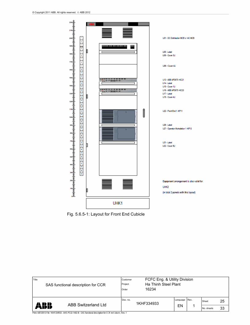
5.9.5 Station Level Cubicle
The cubicle satisfies protection class IP54 according to EN60529.
© Copyright 2011 ABB. All rights reserved. ABB 2012
Title
SAS functional description for CCR
Customer FCFC Eng. & Utility Division Project Ha Thinh Steel Plant Order 16234
Doc. no. Language Rev. Sheet 25
ABB Switzerland Ltd 1KHF334933 EN 1
No. sheets 33 Print: 4/07/2013 File: 1KHF334933 - AHS-PS32-1402-B - SAS functional description for CCR rev1.docm ; Rev. 1
Fig. 5.6.5-1: Layout for Front End Cubicle

© Copyright 2011 ABB. All rights reserved. ABB 2012
Title
SAS functional description for CCR
Customer FCFC Eng. & Utility Division Project Ha Thinh Steel Plant Order 16234
Doc. no. Language Rev. Sheet 26
ABB Switzerland Ltd 1KHF334933 EN 1
No. sheets 33 Print: 4/07/2013 File: 1KHF334933 - AHS-PS32-1402-B - SAS functional description for CCR rev1.docm ; Rev. 1
Fig. 5.6.5-2: Layout for Front End Cubicle

© Copyright 2011 ABB. All rights reserved. ABB 2012
Title
SAS functional description for CCR
Customer FCFC Eng. & Utility Division Project Ha Thinh Steel Plant Order 16234
Doc. no. Language Rev. Sheet 27
ABB Switzerland Ltd 1KHF334933 EN 1
No. sheets 33 Print: 4/07/2013 File: 1KHF334933 - AHS-PS32-1402-B - SAS functional description for CCR rev1.docm ; Rev. 1
7. Appendix: Fiber Optic Cable Specification
7.1 Fiber Optic Components
7.1.1 Fiber Cabling Overview
To better understand fiber performance and operational specifics, we must first look to the fiber cable for a good basis of understanding.
All fiber optic cables consist of three layers:
1. Core - An extremely thin single strand of glass or high quality plastic. This single strand is layer that carries the data.
2. Cladding - Another layer of glass with a slightly different index of refraction from the core. This slight difference can either allow light energy out from the core or keep the majority of energy within the core (via reflections).
3. Jacket - Usually the last outer layer of plastic intended to protect the core and the cladding. The composition of this layer greatly depends on the intended installation
Fig. 7.1-1 Fiber Optic Cable Construction
7.1.2 Fiber Optic Transceiver
A fiber optic transceiver is simply a transmitter receiver pair. A transceiver is tasked with transmitting and receiving data (1’s and 0’s). A fiber optic transceiver accomplishes this task by either turning the light source on or off.
7.1.3 Multi-Mode Communication Links
Multi-mode communication links are generally the most common. When forming a multi-mode link, one must use multi-mode transceivers as well as multi-mode cabling.
Multi-mode fiber cable is generally specified as two numbers such as 62.5/125μm or 50/125μm. This implies a core size of 62.5μm in diameter and a cladding size of 125μm. 62.5/125μm cabling is generally the most popular, followed by 50/125μm. For historical reasons 62.5/125μm cabling has a large install base, but generally 50/125μm cabling is recommended for all new installations to allow for an upgrade path to gigabit (and beyond) speeds.
Multi-mode is called such because the light used to transmit the data actually travels multiple paths within the core. The fiber cable is designed with a core/cladding index difference to keep the majority of light energy within the fiber so that it ’bounces’ around. At the other end of the fiber, a data signal is composed of both the light that took straight paths through the center of the core as well as the light beams that ’bounced’ around. This phenomenon is called modal dispersion and is the primary characteristic that limits multi-mode link distances.

© Copyright 2011 ABB. All rights reserved. ABB 2012
Title
SAS functional description for CCR
Customer FCFC Eng. & Utility Division Project Ha Thinh Steel Plant Order 16234
Doc. no. Language Rev. Sheet 28
ABB Switzerland Ltd 1KHF334933 EN 1
No. sheets 33 Print: 4/07/2013 File: 1KHF334933 - AHS-PS32-1402-B - SAS functional description for CCR rev1.docm ; Rev. 1
7.1.4 Single-Mode Communication Links
Single-mode communication links are less common than multi-mode links, but are quickly gaining ground when longer link distances (> 3 km) are required. When constructing a single-mode link, one must use single-mode transceivers with single-mode cabling.
Single-mode fiber is also specified as two numbers such as 9/125 μm. This implies a core of just 9μm, and a cladding 125μm in diameter. 9/125μm Cabling is generally the most common, followed by 8/125μm.
The whole idea behind a single-mode link path is that light carrying the data travels a single path. Light energy that strays away from the center path leaves the core and become trapped in the cladding due the properties of single-mode cabling. Because almost all the light received at the opposite end travels approximately the same path, modal dispersion (or timing jitter) is no longer a factor. The primary distance-limiting factor for single-mode links is signal power (or amplitude).
7.2 Standard Wavelengths
Fiber optic transceivers generally use four wavelengths (analogous to colors) of light. The following is a table for reference only, as links should be designed with fiber standards in mind as opposed to wavelengths of light.
Fig. 7.2-1 Fiber Optic Wavelengths
7.3 Fiber Optic Standards
The Institute of Electrical and Electronic Engineers (IEEE) is one of the most widely recognized standards body in the world. The IEEE has had a large involvement developing electrical and communications standards including fiber optic communications. The following table lists several of the industry accepted IEEE fiber optic standards:
Fig. 7.3-1 IEEE Fiber Optic Standards

© Copyright 2011 ABB. All rights reserved. ABB 2012
Title
SAS functional description for CCR
Customer FCFC Eng. & Utility Division Project Ha Thinh Steel Plant Order 16234
Doc. no. Language Rev. Sheet 29
ABB Switzerland Ltd 1KHF334933 EN 1
No. sheets 33 Print: 4/07/2013 File: 1KHF334933 - AHS-PS32-1402-B - SAS functional description for CCR rev1.docm ; Rev. 1
7.4 Fiber Optic Cables inside cubicles
This chapter defines the characteristics of the Fiber Optic Cables which are in the scope of ABB and that will be installed inside cubicles.

© Copyright 2011 ABB. All rights reserved. ABB 2012
Title
SAS functional description for CCR
Customer FCFC Eng. & Utility Division Project Ha Thinh Steel Plant Order 16234
Doc. no. Language Rev. Sheet 30
ABB Switzerland Ltd 1KHF334933 EN 1
No. sheets 33 Print: 4/07/2013 File: 1KHF334933 - AHS-PS32-1402-B - SAS functional description for CCR rev1.docm ; Rev. 1

© Copyright 2011 ABB. All rights reserved. ABB 2012
Title
SAS functional description for CCR
Customer FCFC Eng. & Utility Division Project Ha Thinh Steel Plant Order 16234
Doc. no. Language Rev. Sheet 31
ABB Switzerland Ltd 1KHF334933 EN 1
No. sheets 33 Print: 4/07/2013 File: 1KHF334933 - AHS-PS32-1402-B - SAS functional description for CCR rev1.docm ; Rev. 1

© Copyright 2011 ABB. All rights reserved. ABB 2012
Title
SAS functional description for CCR
Customer FCFC Eng. & Utility Division Project Ha Thinh Steel Plant Order 16234
Doc. no. Language Rev. Sheet 32
ABB Switzerland Ltd 1KHF334933 EN 1
No. sheets 33 Print: 4/07/2013 File: 1KHF334933 - AHS-PS32-1402-B - SAS functional description for CCR rev1.docm ; Rev. 1

© Copyright 2011 ABB. All rights reserved. ABB 2012
Title
SAS functional description for CCR
Customer FCFC Eng. & Utility Division Project Ha Thinh Steel Plant Order 16234
Doc. no. Language Rev. Sheet 33
ABB Switzerland Ltd 1KHF334933 EN 1
No. sheets 33 Print: 4/07/2013 File: 1KHF334933 - AHS-PS32-1402-B - SAS functional description for CCR rev1.docm ; Rev. 1
8. Revision
Rev. Page (P) Chapt. (C)
Description Date Dept./Init.
0 - First Issue 2013-01-11 / SL
1 6-7, 2.3
8-9, 3.1
9, 3.1.1
9, 3.1.2
9, 3.1.3
9, 3.2
12, 5.1.2
16, 5.3.1
16, 5.3.2
16, 5.4
16, 5.5
18, 5.7
18, 5.7.1
24-27, 7.4
Customer comments 2013-04-09 and week 17 2013. Changes highlighted in blue
2013-05-14 / SL