1m23n33702 cgy760r 3d coverpage(e) · • other functions 0d[lpxp 530 phpru\ &xpxodwlyh hqjlqh...
TRANSCRIPT
1M23N33702
INSTRUCTION MANUAL
Futaba CGY760R is receiver, 3-axis Stabilization System combining AVCS gyro and
MEMS (Micro Electro Mechanical System) sensor design, ultra high-speed process-
INTRODUCTION
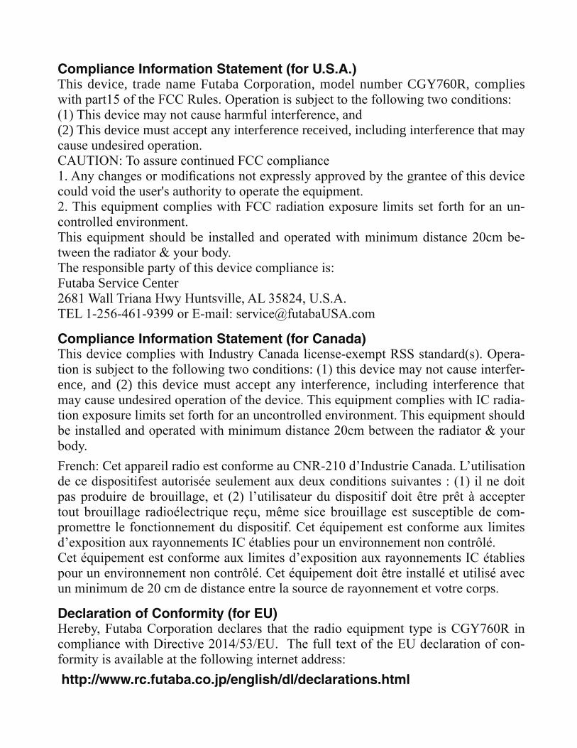
Compliance Information Statement (for U.S.A.)This device, trade name Futaba Corporation, model number CGY760R, complies
(2) This device must accept any interference received, including interference that may
-
-
Futaba Service Center
Compliance Information Statement (for Canada)--
ence, and (2) this device must accept any interference, including interference that -
-
Declaration of Conformity (for EU)
-
http://www.rc.futaba.co.jp/english/dl/declarations.html
4
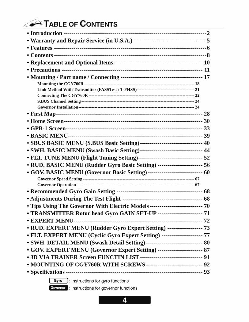
TABLE OF CONTENTS • Introduction -------------------------------------------------------------------------2• Warranty and Repair Service (in U.S.A.)--------------------------------------5• Features ------------------------------------------------------------------------------6• Contents ------------------------------------------------------------------------------8 • Replacement and Optional Items --------------------------------------------- 10• Precautions ------------------------------------------------------------------------ 11• Mounting / Part name / Connecting ------------------------------------------ 17
Mounting the CGY760R --------------------------------------------------------------------------- 18Link Method With Transmitter (FASSTest / T-FHSS) --------------------------------------- 21Connecting The CGY760R ------------------------------------------------------------------------ 22S.BUS Channel Setting ----------------------------------------------------------------------------- 24Governor Installation ------------------------------------------------------------------------------- 24
• First Map --------------------------------------------------------------------------- 28• Home Screen ----------------------------------------------------------------------- 30• GPB-1 Screen ---------------------------------------------------------------------- 33• BASIC MENU--------------------------------------------------------------------- 39• SBUS BASIC MENU (S.BUS Basic Setting) -------------------------------- 40• SWH. BASIC MENU (Swash Basic Setting) -------------------------------- 44• FLT. TUNE MENU (Flight Tuning Setting) --------------------------------- 52• RUD. BASIC MENU (Rudder Gyro Basic Setting) ----------------------- 56• GOV. BASIC MENU (Governor Basic Setting) ---------------------------- 60
Governor Speed Setting ---------------------------------------------------------------------------- 67Governor Operation -------------------------------------------------------------------------------- 67
• Recommended Gyro Gain Setting -------------------------------------------- 68• Adjustments During The Test Flight ----------------------------------------- 68• Tips Using The Governor With Electric Models --------------------------- 70• TRANSMITTER Rotor head Gyro GAIN SET-UP ----------------------- 71• EXPERT MENU ------------------------------------------------------------------ 72• RUD. EXPERT MENU (Rudder Gyro Expert Setting) ------------------ 73• FLT. EXPERT MENU (Cyclic Gyro Expert Setting) --------------------- 77• SWH. DETAIL MENU (Swash Detail Setting) ----------------------------- 80• GOV. EXPERT MENU (Governor Expert Setting) ----------------------- 87• 3D VIA TRAINER Screen FUNCTIN LIST -------------------------------- 91• MOUNTING OF CGY760R WITH SCREWS ----------------------------- 92
---------------------------------------------------------------------- 93 Gyro : Instructions for gyro functions
Governor : Instructions for governor functions

5
Technical updates and additional programming examples can be found at: www.futabausa.com
WARRANTY & REPAIR SERVICE (IN U.S.A.)
to your hobby dealer or contact the Futaba Service Center at the e-mail address, fax
Phone:1-256-461-9399, FAX:1-256-461-1059 E-Mail: [email protected]
-
• System (Transmitter, Receiver, Servos and model numbers) • Model (Model name) • Your Name, Address and Telephone number
Futaba Corporation of America2681 Wall Triana Hwy
Huntsville, AL 35824, U.S.A.
6
FEATURES
•
• Gyro section
Rudder (yaw) section:
•
• -
• Cutting edge control algorithm provides a consistent pirouette rate, precise op-
Aileron, Elevator (roll, pitch) section:
• Governor section
•
7
• Receiver section
information of the receiver and the optional sensor information connected to the
• Other functions
8
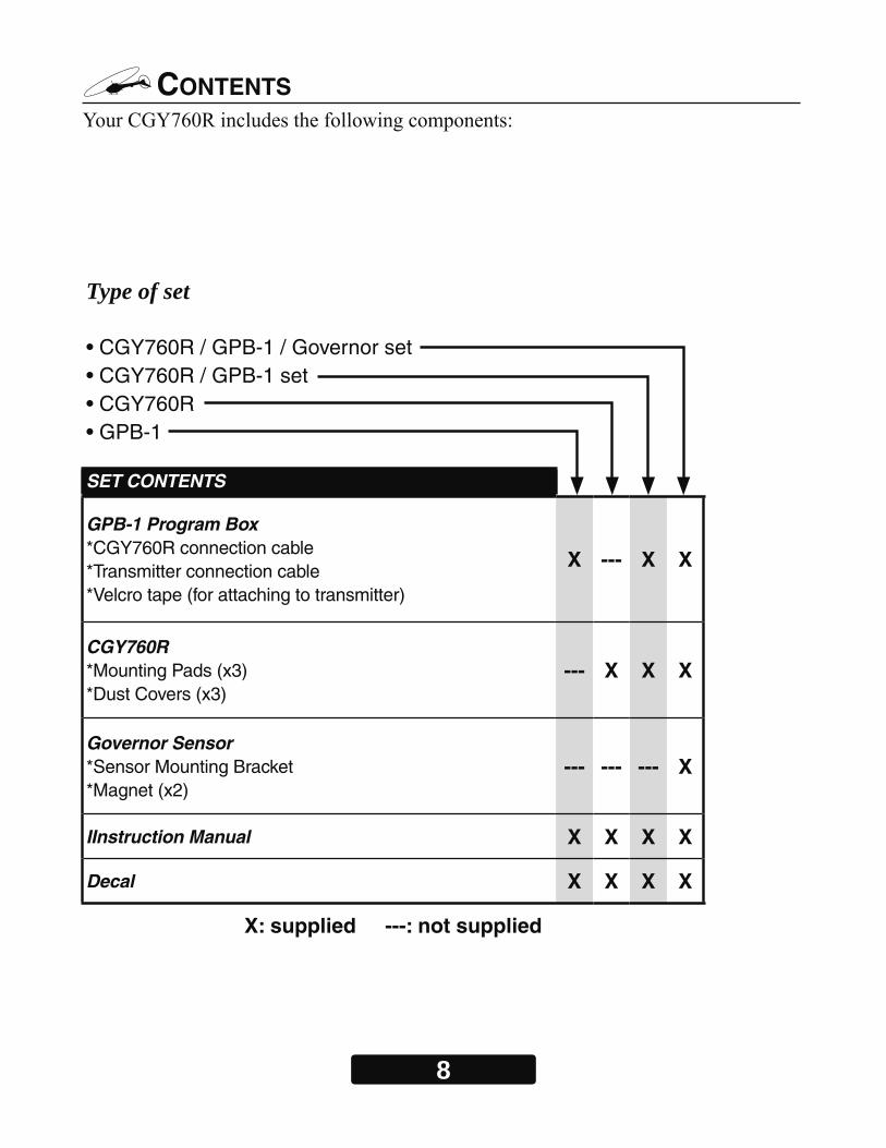
CONTENTS
Type of set
• CGY760R / GPB-1 / Governor set• CGY760R / GPB-1 set• CGY760R• GPB-1
SET CONTENTS
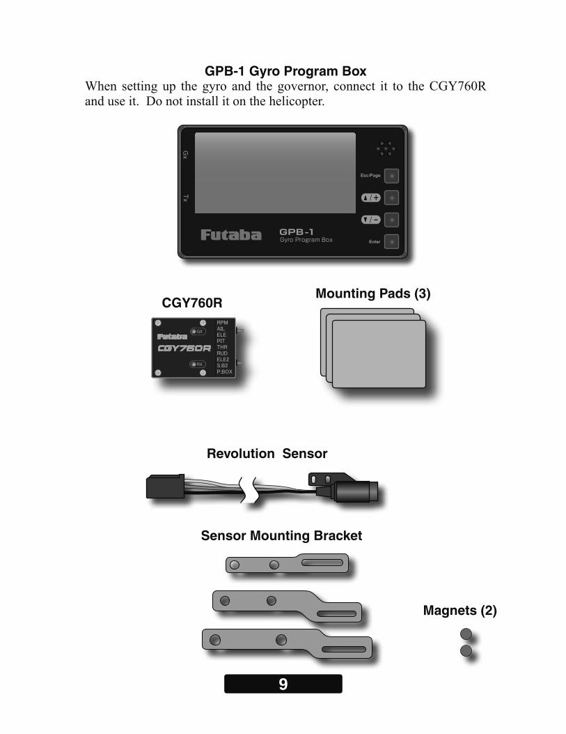
GPB-1 Program Box*CGY760R connection cable*Transmitter connection cable*Velcro tape (for attaching to transmitter)
X --- X X
CGY760R*Mounting Pads (x3)*Dust Covers (x3)
--- X X X
Governor Sensor*Sensor Mounting Bracket*Magnet (x2)
--- --- --- X
IInstruction Manual X X X X
Decal X X X X
X: supplied ---: not supplied
9
Sensor Mounting Bracket
GPB-1 Gyro Program Box
CGY760R
Magnets (2)
Mounting Pads (3)
Revolution Sensor

10
Futaba PC Interface CIU-2 / CIU-3
Governor Revolution Sensor Set
Mounting Pad (10)
Sensor Mounting Bracket Set
Backplate Sensor BPS-1
Transmitter Connection Cord
Dust Cover (3)
REPLACEMENT & OPTIONAL ITEMS
CGY760R Connection Cord
11
PRECAUTIONS
Meaning of Special Markings
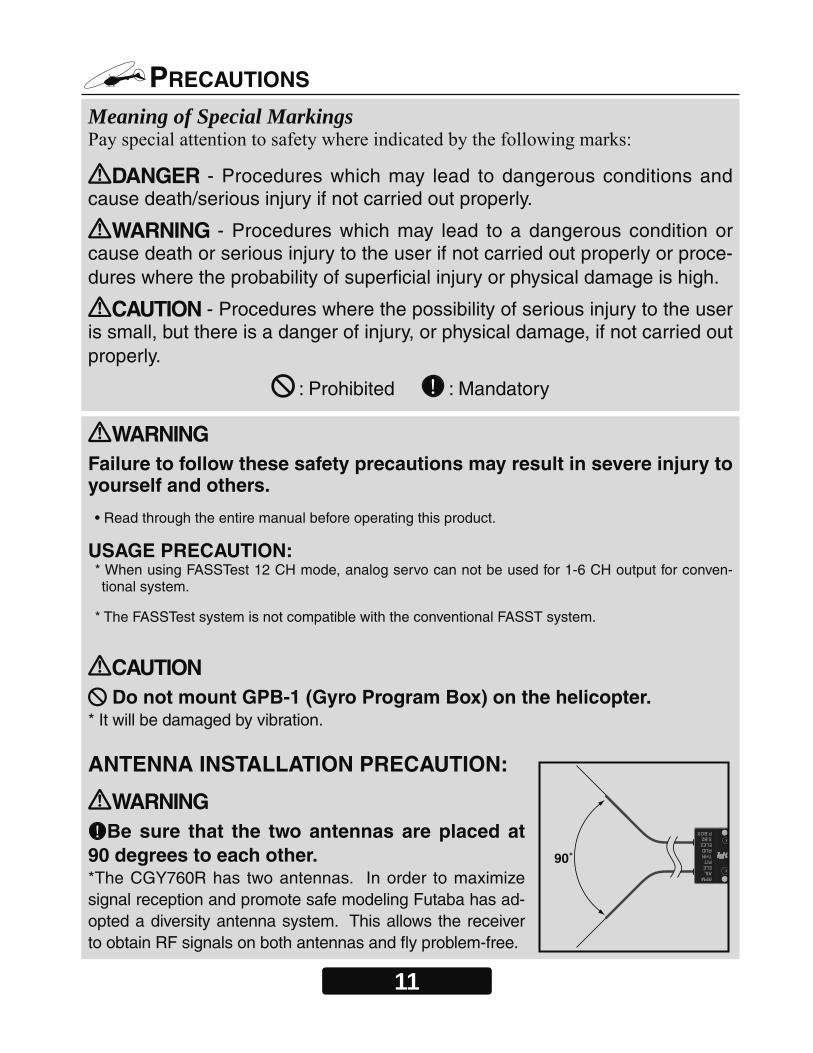
DANGER - Procedures which may lead to dangerous conditions and cause death/serious injury if not carried out properly.
WARNING - Procedures which may lead to a dangerous condition or cause death or serious injury to the user if not carried out properly or proce-dures where the probability of superficial injury or physical damage is high.
CAUTION - Procedures where the possibility of serious injury to the user is small, but there is a danger of injury, or physical damage, if not carried out properly.
: Prohibited : Mandatory
WARNING Failure to follow these safety precautions may result in severe injury to yourself and others.
• Read through the entire manual before operating this product.
USAGE PRECAUTION:* When using FASSTest 12 CH mode, analog servo can not be used for 1-6 CH output for conven-tional system.
* The FASSTest system is not compatible with the conventional FASST system.
CAUTION Do not mount GPB-1 (Gyro Program Box) on the helicopter.
* It will be damaged by vibration.
ANTENNA INSTALLATION PRECAUTION:
WARNING Be sure that the two antennas are placed at
90 degrees to each other.*The CGY760R has two antennas. In order to maximize signal reception and promote safe modeling Futaba has ad-opted a diversity antenna system. This allows the receiver to obtain RF signals on both antennas and fly problem-free.
90˚
12
Do not cut or bundle the receiver antenna wire.
Do not bend the coaxial cable. It causes damage.
To prevent damage to the antenna, please exercise caution. Do not bend at the base of the antenna. Also, ensure that the unit is not sub-jected to impact damage.
Keep the antenna as far away from the motor, ESC and other noise sources as you possibly can.
CARBON FUSELAGE PRECAUTION:WARNING You must leave 30mm at the tip of the antenna fully exposed. The
exposed antenna should be secured so that it can not move around or back inside of your aircraft.
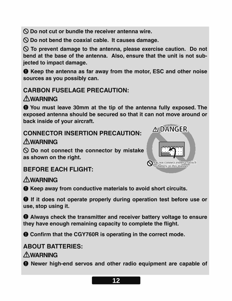
CONNECTOR INSERTION PRECAUTION:WARNING Do not connect the connector by mistake
as shown on the right.
BEFORE EACH FLIGHT:
WARNING Keep away from conductive materials to avoid short circuits.
If it does not operate properly during operation test before use or use, stop using it.
Always check the transmitter and receiver battery voltage to ensure they have enough remaining capacity to complete the fl ight.
Confi rm that the CGY760R is operating in the correct mode.
ABOUT BATTERIES:WARNING Newer high-end servos and other radio equipment are capable of
Do not connect either a switch or battery in this manner.Do not connect either a switch or battery in this manner.
DANGERDANGER

13
placing large demands on the power systems in use today. When us-ing a regulator you must ensure that the regulator is capable of sup-plying the current demands of the equipment you have selected. In addition to this make sure the wiring and switch you have selected are capable of handling high current draws. *The servo current draw can be up to 50% higher on a flybarless helicopter. Always en-sure your receiver battery is fully charged before each flight.
ABOUT CONNECTOR: Insert the connector such as sensor, servo, connection cord, battery
etc., surely.*If it is not securely inserted all the way in, it may come off due to vibration during flight and there is a danger of falling.
ABOUT WIRING: Please secure the wiring so that it does not rub against the helicop-
ter frame or other such items that could cause wear. If it does so, we suggest covering these ares with fuel tubing (or similar) to prevent damage.
ABOUT VIBRATION ISOLATION AND WATERPREEFING: The CGY760R is fixed with a dedicated mounting pad with good
condition and the helicopter performs sufficient anti-vibration mea-sures so as not to receive strong vibration at the time of flight. Also, if there is a risk of the gyro getting wet, place it in a plastic bag and take waterproof measures.
ON FLIGHT PRECAUTION: Always exit programming mode before attempting to fly the model.
Gyro operating precautions: Gyro
The CGY760R requires 5-10 seconds to initialize when the power is turned on. Do not move the helicopter and do not move the tail rotor, aileron and elevator sticks during this initialization or the gyro may not initialize properly. Once the initialization process has been completed the swash servos and tail servo will move several times indicating that
14
the CGY760R is now ready for flight.
Verify that the gyros are operating and compensating in the correct direction before each flight. If the compensation direction is incorrect on any axis the model will become uncontrollable after takeoff.
The servo type parameters within the CGY760R must match the type of servo you are using. Incorrect setting may damage the CGY760R or the servos, possibly resulting in a loss of control during flight.
Always allow the gyro to adjust to the surrounding environmental temperature before flight. A large temperature change during use will cause drift and other operational issues.
If you are switching between Normal Mode and AVCS Mode in flight, please keep in mind that you must have the gyro re-learn the center position after making a trim change within the transmitter. To memorize the new center position simply flip the gain switch on the transmitter three times between Normal Mode and AVCS Mode (Normal AVCS
Normal AVCS) within one second. The servo will center indicating that the new center position has been memorized.
When operating the gyro in AVCS Mode, all compensation and revo-lution mixing must be disabled and any tail rotor or swash offsets for flight modes must be disabled.
Do not drop the CGY760R onto a hard surface or subject the CGY760R sensor to a strong shock as this may damage the sensor.
Verify that the gyro is operating in the desired mode.
When the CGY760R is operated in AVCS mode the tail rotor or swash plate servos will not center when tail rotor, aileron or rudder stick is released. This is normal operation for AVCS mode. The servos may also move to the extent while the model is being carried out to the flight line. Before take off, you must visually center the tail rotor pitch slider and level the swash plate by using the transmitter control sticks. You can also center the servos by moving the tail rotor stick full left, then full right, back to full left and then allow the stick to center within
15
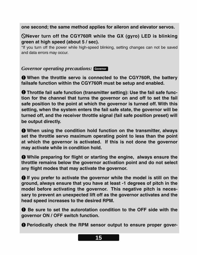
one second; the same method applies for aileron and elevator servos.
Never turn off the CGY760R while the GX (gyro) LED is blinking green at high speed (about 5 / sec).*If you turn off the power while high-speed blinking, setting changes can not be saved and data errors may occur.
Governor operating precautions: Governor
When the throttle servo is connected to the CGY760R, the battery failsafe function within the CGY760R must be setup and enabled.
Throttle fail safe function (transmitter setting): Use the fail safe func-tion for the channel that turns the governor on and off to set the fail safe position to the point at which the governor is turned off. With this setting, when the system enters the fail safe state, the governor will be turned off, and the receiver throttle signal (fail safe position preset) will be output directly.
When using the condition hold function on the transmitter, always set the throttle servo maximum operating point to less than the point at which the governor is activated. If this is not done the governor may activate while in condition hold.
While preparing for flight or starting the engine, always ensure the throttle remains below the governor activation point and do not select any flight modes that may activate the governor.
If you prefer to activate the governor while the model is still on the ground, always ensure that you have at least -1 degrees of pitch in the model before activating the governor. This negative pitch is neces-sary to prevent an unexpected lift off as the governor activates and the head speed increases to the desired RPM.
Be sure to set the autorotation condition to the OFF side with the governor ON / OFF switch function.
Periodically check the RPM sensor output to ensure proper gover-
16
nor operation. Due to the high level of vibration and centrifugal forces the magnet may come loose or the sensor alignment may change. Ev-ery 10th flight verify that the magnet and sensor are properly mounted.
If abnormality such as vibration etc., is recognized on the aircraft side during operation, be prepared to turn off the governor immedi-ately.
MACHINE MAINTENANCE:WARNING Even though the CGY760R is a high performance gyro and governor,
it will be necessary to ensure that the helicopter mechanics are also in optimum operating condition. Please use the guidelines below and address all issues before installing and flying the CGY760R.
• The CGY760R must be used with a rigid tail rotor drive system. Any mod-ern torque tube or belt drive system should be adequate. Do not attempt to fly the CGY760R using a wire driven tail rotor system.
• Always ensure the drive gears, torque tube, pulleys, belt, bearings and shafts are in proper working condition. If any of these items are damaged or worn they must be replaced.
• The linkage rod, tail rotor bell crank, pitch slider and tail rotor grips must operate without friction to obtain the best performance from the CGY760R. Binding in the tail rotor control linkage will decrease the performance of the CGY760R gyro and this may also shorten the servo lifespan. Please take the time now to ensure the tail rotor system on your helicopter is working correctly and without friction or binding.
• Vibration will affect the CGY760R’s overall performance. All rotating components on the helicopter should be balanced to minimize vibrations in flight. Ensure that your engine or electric motor is running smoothly and that all vibrations have been addressed before installing and test flying the CGY760R.
17
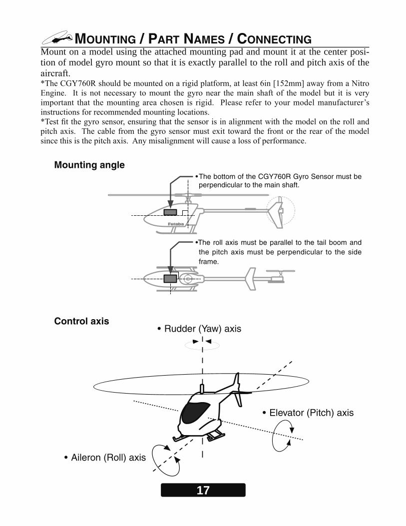
MOUNTING / PART NAMES / CONNECTING Mount on a model using the attached mounting pad and mount it at the center posi-tion of model gyro mount so that it is exactly parallel to the roll and pitch axis of the
Mounting angle• The bottom of the CGY760R Gyro Sensor must be perpendicular to the main shaft.
•The roll axis must be parallel to the tail boom and the pitch axis must be perpendicular to the side frame.
Control axis
• Elevator (Pitch) axis
• Rudder (Yaw) axis
• Aileron (Roll) axis
18
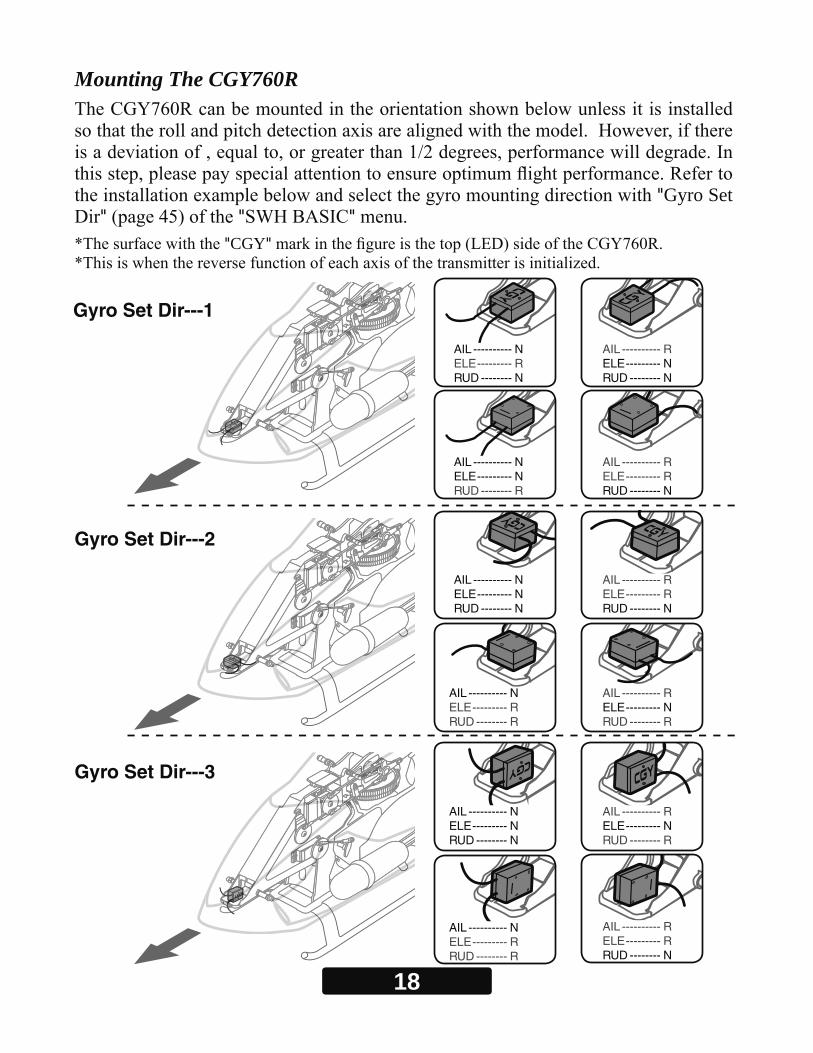
AIL ---------- NELE --------- RRUD -------- N
AIL ---------- RELE --------- NRUD -------- N
AIL ---------- NELE --------- NRUD -------- R
AIL ---------- RELE --------- RRUD -------- N
AIL ---------- NELE --------- NRUD -------- N
AIL ---------- RELE --------- RRUD -------- N
AIL ---------- NELE --------- RRUD -------- R
AIL ---------- RELE --------- NRUD -------- R
AIL ---------- RELE --------- NRUD -------- R
AIL ---------- NELE --------- NRUD -------- N
AIL ---------- RELE --------- RRUD -------- N
AIL ---------- NELE --------- RRUD -------- R
Mounting The CGY760R
"Gyro Set " " "
"CGY"
Gyro Set Dir---1
Gyro Set Dir---2
Gyro Set Dir---3

19
Gyro Set Dir---4
Gyro Set Dir---5
Gyro Set Dir---6
AIL ---------- RELE --------- RRUD -------- R
AIL ---------- RELE --------- RRUD -------- R
AIL ---------- NELE --------- NRUD -------- N
AIL ---------- NELE --------- NRUD -------- R
AIL ---------- RELE --------- NRUD -------- N
AIL ---------- NELE --------- RRUD -------- N
AIL ---------- RELE --------- NRUD -------- R
AIL ---------- NELE --------- NRUD -------- R
AIL ---------- NELE --------- RRUD -------- R
AIL ---------- RELE --------- RRUD -------- R
*Depending on the type of mounting plate, it is also possible to mount as shown in the fi gure.
*Depending on the type of mounting plate, it is also possible to mount as shown in the fi gure.
It is necessary to set the motion direction of each gyro by "AGy.Dir", "EGy.Dir" of "SWH. BASIC" menu (page 49) and "Gyro.Dir" of "RUD BASIC" menu (page 57). AIL - Aileron (Roll) axis / ELE - Elevator (Pitch) axis / RUD - Rudder (Yaw) axis
N --- Normal / R --- Reverse
AIL ---------- RELE --------- NRUD -------- N
AIL ---------- NELE --------- RRUD -------- N
20
*Please install the CGY760R as it is in the center (vertical direction and horizontal
The CGY760R Troubleshooting Tips
1. Always verify that the tail rotor and swash plate mechanisms operate, and that the drive system is in proper working order.
2. Electromagnetic interference could be causing the problem. If you feel everything is set up correctly and that the model is vibration free, then consider moving the gyro sensor to a new location away from servos, ESC, and drive motors.
3. Vibrations will decrease the performance of all gyro systems. Even though the CGY760R gyro sensor is the most vibration resistant gyro sensor available, eliminat-ing vibrations will always improve performance. The CGY760R gyro sensor performs best when the sensor is mounted rigidly to the airframe. It is highly recommended to avoid using soft foam pads as this may allow the gyro to bounce around on the roll and pitch axis, causing instabilities and possible loss of control during flight so that the roll and pitch sensing axis are in alignment with the model. Any misalignments over 1/2 of a degree will cause a loss in performance. Please take extra care in this step to ensure the optimum flight performance.
Using The CGY760R With An Electric Model
DANGER It is necessary to remove the pinion gear from the electric motor or
disconnect the motor from the ESC before powering the model up for setup or bench testing. Electric motors are extremely powerful and capable of delivering the power instantly, causing injury to yourself, others, or the surroundings.
21
WARNING
Do not perform the linking procedure while the motor’s main wire connected or the engine is operating as it may result in serious injury.
When the linking is complete, please cycle the receiver power and ensure the receiver is properly linked to the transmitter.
Please power up your system in this order. Transmitter first, fol-lowed by the receiver.
If the CGY760R was previously linked to another transmitter, make sure that transmitter is not operating while linking the receiver to the new transmitter.
refer to page 70 of this manual for further suggestions on the use of the governor of
Link Method With Transmitter (FASSTest / T-FHSS)
1. Connect the CGY760R and GPB-1 and set the same mode set in as the transmitter linking the CGY760R communication mode on the "Receiver" screen. (See page 36)
2. Keep the transmitter and receiver close to each other and turn on the receiver with the transmitter in the link mode.
3. After powering on the receiver, please allow for approximately two seconds for the binding/linking to occur.
4. The LED indication on the receiver will change from the red blinking light to a solid green. This indicates that the linking is successful. This usually occurs in approxi-mately one second.
* Refer to the transmitters instruction manual for complete details on how to place the transmitter into the linking mode.
* If there are many T-FHSS or FASSTest systems in use when attempting to link the transmitter to the receiver, it might require more time to do so.
Additionally, if another modeler in close proximity is attempting to link their units si-multaneously, it could also cause difficulties as the receiver might inadvertently link to the other transmitter. Always confirm that the receiver responds to the input from the desired transmitter.
* If the System Type of the transmitter is changed, the receiver will need to be re-linked to the transmitter. For example, if the transmitter is changed from T-FHSS to FASST-est, it will be necessary to perform the linking procedure once again.

22
GX (Gyro) LED
LCD• Displays menus,
parameters.
Edit key• Used to set operat-
ing parameters.
RX (Receiver) LED
LED State
Solid red Normal operation.
Blinking green
Normal blinking (about 2 / sec): S.BUS data wait time.High-speed blinking(about 5 / sec): Backing up data.
Never shut down during backup.
Blinking red
Indicates an error has occurred. For example, the gyro is not func-tioning correctly. If normal operation does not return after cycling the power off/on once again and/or replacing the battery, please contact our customer service department.
LED State
Solid green Normal operation.
Solid red No signal reception
Red and Green turn on
alternately
Unrecoverable failure (EEPROM,etc.)Cycle the power off/on once again to return to normal operation. If this is not successful, please contact our customer service center.
(9) P.BOX: • Connect to CGY760R when making settings. When setting is completed remove it.
(10) Transmitter Connection Cable: • Connect when using the transmitter to wirelessly transfer settings of
GPB-1 to CGY760R.
Connecting The CGY760R
23
Terminal box
Hub
Hub
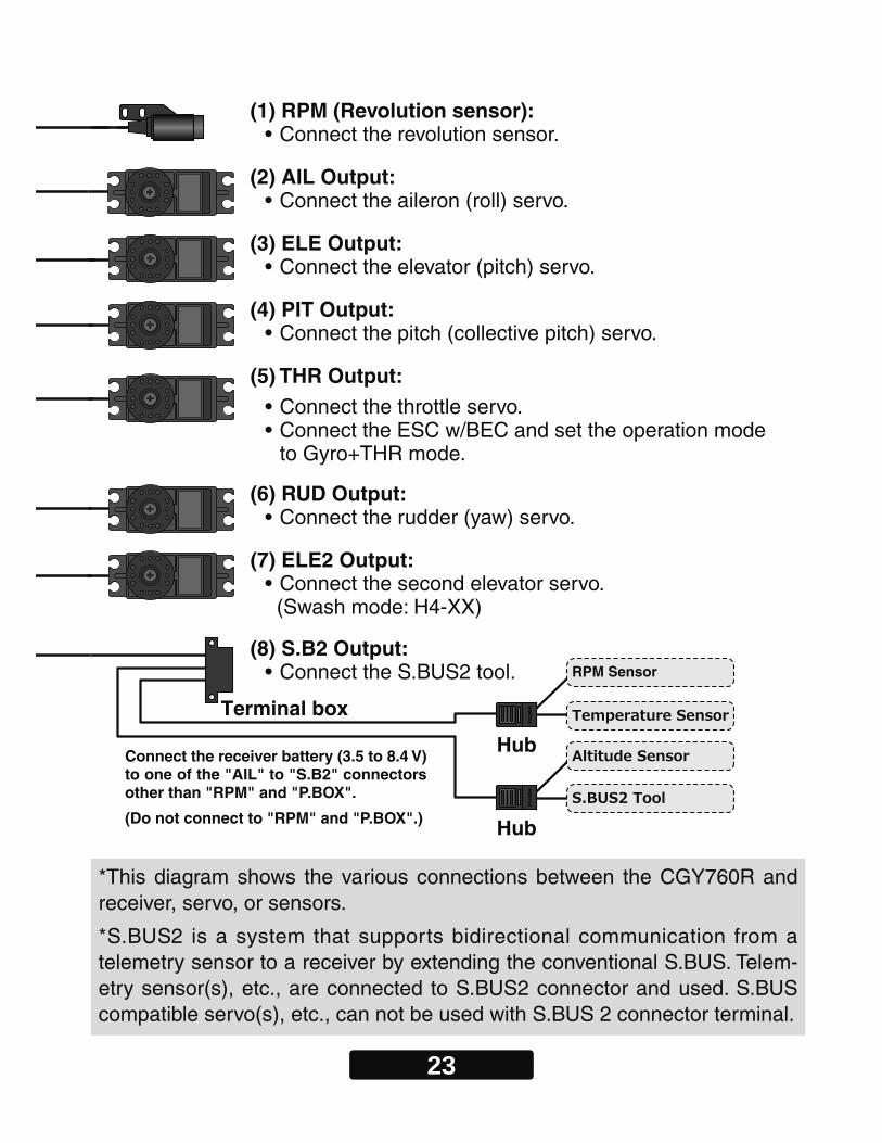
RPM Sensor
(1) RPM (Revolution sensor): • Connect the revolution sensor.
(2) AIL Output: • Connect the aileron (roll) servo.
(3) ELE Output: • Connect the elevator (pitch) servo.
(4) PIT Output: • Connect the pitch (collective pitch) servo.
(6) RUD Output: • Connect the rudder (yaw) servo.
(7) ELE2 Output: • Connect the second elevator servo. (Swash mode: H4-XX)
(8) S.B2 Output: • Connect the S.BUS2 tool.
(5) THR Output: • Connect the throttle servo.• Connect the ESC w/BEC and set the operation mode
to Gyro+THR mode.
*This diagram shows the various connections between the CGY760R and receiver, servo, or sensors.
*S.BUS2 is a system that supports bidirectional communication from a telemetry sensor to a receiver by extending the conventional S.BUS. Telem-etry sensor(s), etc., are connected to S.BUS2 connector and used. S.BUS compatible servo(s), etc., can not be used with S.BUS 2 connector terminal.
Connect the receiver battery (3.5 to 8.4 V) to one of the "AIL" to "S.B2" connectors other than "RPM" and "P.BOX".
(Do not connect to "RPM" and "P.BOX".)
24
S.BUS Channel Setting
-
1. The "SBUS BASIC" menu (page 40 as of this draft.) of CGY760R is displayed.
2. Use the [ /+] or [ /-] key to select "AIL CH #" and press the [Enter] key to enter setting mode. Check the transmitter’s aileron channel and set it to match the channel with the [/+] or [ /-] key. When you are done, press [Enter] key to exit setting mode.
3. Perform the same operation as above and set the function (such as aileron, pitch, col-lective, tail rotor gain, rotor head gain, RPM, gv on/off) channels to the transmitter.
4. If your transmitter does not offer enough channels to operate all of the CGY760R’s functions, it is possible to operate the CGY760R without the Gov SW, Rotor Head Gain channels connected. When any of these functions are not used, it is necessary to set the channel number to "INH" within the CGY760R’s S.BUS menu. Doing so disables the function and enables the user of the value set in the CGY760R menu ac-cordingly.
When the Gov SW channel is not used, the governor on/off control is handled by the [Stick Switch] function.
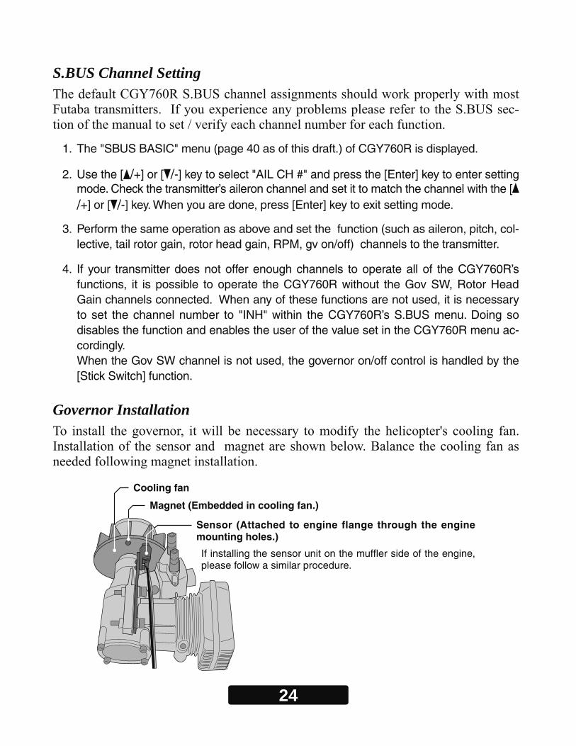
Governor Installation
Cooling fan
Magnet (Embedded in cooling fan.)
Sensor (Attached to engine flange through the engine mounting holes.)
If installing the sensor unit on the muffler side of the engine, please follow a similar procedure.

25
Magnet Operating Side CheckBring the magnet near the end of the sensor and check the operating side.
* This is the side at which the displayed value increases in the "Revolution sensor testing" menu within the "Governor Basic Setting" section earlier in this manual. Install the mag-net with this side facing the sensor. Mark this side of the magnet with a felt tip pen.
1. Drill a hole in the fan at the magnet mounting position. Make the hole about 4.1mm in diameter and 1.5 to 1.7mm deep.
2. Embed the magnet in this hole in the direction in which an output is obtained. Use epoxy adhesive that cures in 30 minutes or longer. Do not use epoxies that contain metal such as JB Weld.
SensorMagnet
3. If the cooling fan is unbalanced and vibrates, etc., balance it by mounting the spare magnet to the opposite side of the cooling fan in the opposite polarity (so that it does not output a signal).
Magnet
Cement the magnet to the cool-ing fan so that the magnet is level with this side of the cooling fan.
Sensor MountingThe sensor mounting method depends on the model and engine.
1. Temporary the sensor to the sensor mount.
2. Drill a hole in the fan cover at the part corresponding to the sensor so that the distance between the sensor and magnet can be made 1 to 2mm.

26
Sensor Adjustment1. Adjust the sensor position to obtain a sensor output of at least 60% in the "Revolution
sensor testing" menu within the "Governor Basic Setting" .
SensorSensor case
Center of sensor is offset.
Magnet
2.2mm1 - 2mm
3.7mm 3.7mm
2. The center of the sensor is different from the center of the sensor case so be careful when mounting the sensor.
If the display is less than 60% when the magnet is directly below the sensor, bring the sensor closer to the magnet so that the 60% or more is displayed. The magnet and sensor gap criteria is approximately 1 to 2mm. If a sensor output is not obtained even when the sensor is brought close to the magnet, the magnet and sensor center posi-tions may have changed.
3. Complete assembly of the sensor by securely tightening the screws that were tempo-rarily tightened.
4. Recheck the sensor output.
3. Tighten the sensor stay together with the engine mounting flange. (Temporary assembly)
4. Select the mounting method so that the sensor does not touch the frame, or other parts of the model. Temporarily mount the sensor and select the magnet mounting position.
5. Install the sensor to the sensor stay using the accessory screws and washers.
6. Tighten the sensor stay together with the engine using the engine mount screw.
27
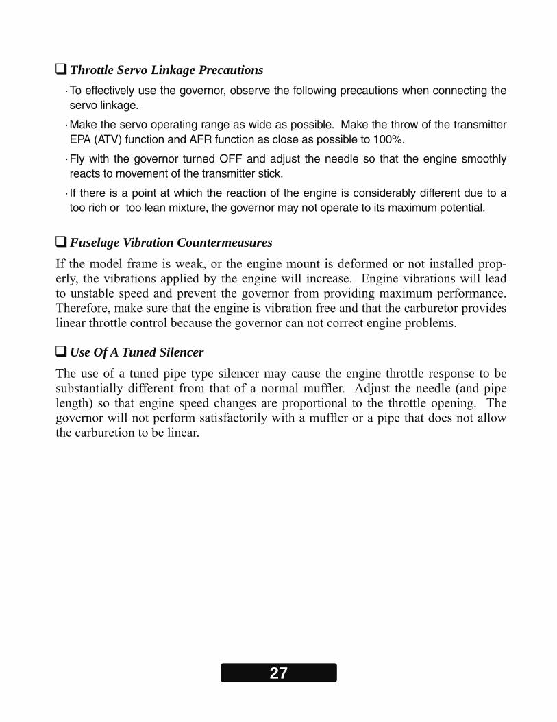
Throttle Servo Linkage Precautions· To effectively use the governor, observe the following precautions when connecting the servo linkage.
· Make the servo operating range as wide as possible. Make the throw of the transmitter EPA (ATV) function and AFR function as close as possible to 100%.
· Fly with the governor turned OFF and adjust the needle so that the engine smoothly reacts to movement of the transmitter stick.
· If there is a point at which the reaction of the engine is considerably different due to a too rich or too lean mixture, the governor may not operate to its maximum potential.
Fuselage Vibration Countermeasures-
Use Of A Tuned SilencerThe use of a tuned pipe type silencer may cause the engine throttle response to be

28
FIRST MAPConnect GPB-1 (Gyro Program Box) And CGY760R
-
Opening Screen And Home Screen
CGY760R Connection Cable
It is used to connect the CGY760R and the Gyro Pro-gram Box GPB-1.
Connect the receiver battery (3.5 to 8.4 V) to one of the "AIL" to "S.B2" connectors other than "RPM" and "P.BOX".
(Do not connect to "RPM" and "P.BOX".)
Connect the battery
Opening screen Home screen
CAUTIONBe sure to connect and d isconnect the
CGY760R and GPB-1 connect ion cord wi th the power o f f .
29
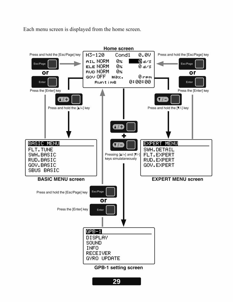
Home screen
BASIC MENU screen EXPERT MENU screen
GPB-1 setting screen
Pressing [ /+] and [ /-] keys simulataneously
Press the [Enter] key
Press the [Enter] key Press the [Enter] key
Press and hold the [Esc/Page] key
Press and hold the [Esc/Page] key
Press and hold the [ /+] key Press and hold the [ /-] key
Press and hold the [Esc/Page] key

30
HOME SCREENHome Screen Display 1 2
4
6
7
8
5
3
Home screen1. Swash plate typeDisplays the swash plate type set in "SWH. BASIC" menu.
2. Condition numberWith switch operation from the transmitter, several parameters can be switched by setting up to 5 types of data. If you set the condition switch to the channel having the AFR func-tion of the transmitter and set the point for each fl ight condition with the AFR point curve, it can also be linked with the fl ight condition switch.
•When either the DG1 or DG 2 switch is selected, the following options are available.
Function Menu of your transmitter (DG1). Assigning DG1 to a switch or fl ight mode allows the use of two separate values for the condition selectable parameters.
●SWS.Rate●PIT.Rate●SWS.Ring●FLT.Styl
●Cnt.AuthAI●Cnt.AuthEL●EXPO●HeadHld A
●HeadHld E●StpTune A●StpTune E●CYC.Rt
●GOV.Gain●L Lmt.Hov●L Lmt.IdUp
Cond1 (Condition 1)
Switch DG1
●SWS.Rate●PIT.Rate●SWS.Ring●FLT.Styl
●Cnt.AuthAI●Cnt.AuthEL●EXPO●HeadHld A
●HeadHld E●StpTune A●StpTune E●CYC.Rt
●GOV.Gain●L Lmt.Hov●L Lmt.IdUp
Cond2 (Condition2)
Neutral
Switch Channel Rate
WideNarrow
Cond1 Cond2
-100% 100%-35% 35%0%
*Indicates when the setup style is "3D".
For functions that can set conditions in this manual, mark Cond is written.

31
•If you set a condition switch channel, using the AFR function on that channel set a flat point curve for each flight condition. Then you can utilize all 5 flights conditions.
Set the point curve with AFR for each flight condition of the transmitter.
Switch Channel RateNeutral
Cond1 Cond3 Cond5Cond4Cond2
-100% 100%-25%-75% 75%25%0%
-100%
100%
0%
3. Battery voltageDisplays the voltage of the receiver battery connected to CGY760R.
4. Gyro operation mode / Gyro gainDisplays "AVCS" or "Normal" operation mode and gyro gain of aileron (roll), elevator (pitch) and rudder (yaw) axis.
5. Roll and Elevator rate maximum displayThis screen displays the maximum roll rate and maximum elevator rate recorded during flight. Data is reset when the power is turned off. If you want to check the maximum rate, leave the power on after flight. Use the [ /+] or [ /-] key to move the cursor to each rate display and press and hold [Enter] key to reset the display.
6. Governor ON / OFFIndicates the ON / OFF switch status of the governor function. When "ON" is displayed, the governor function is activated.
32
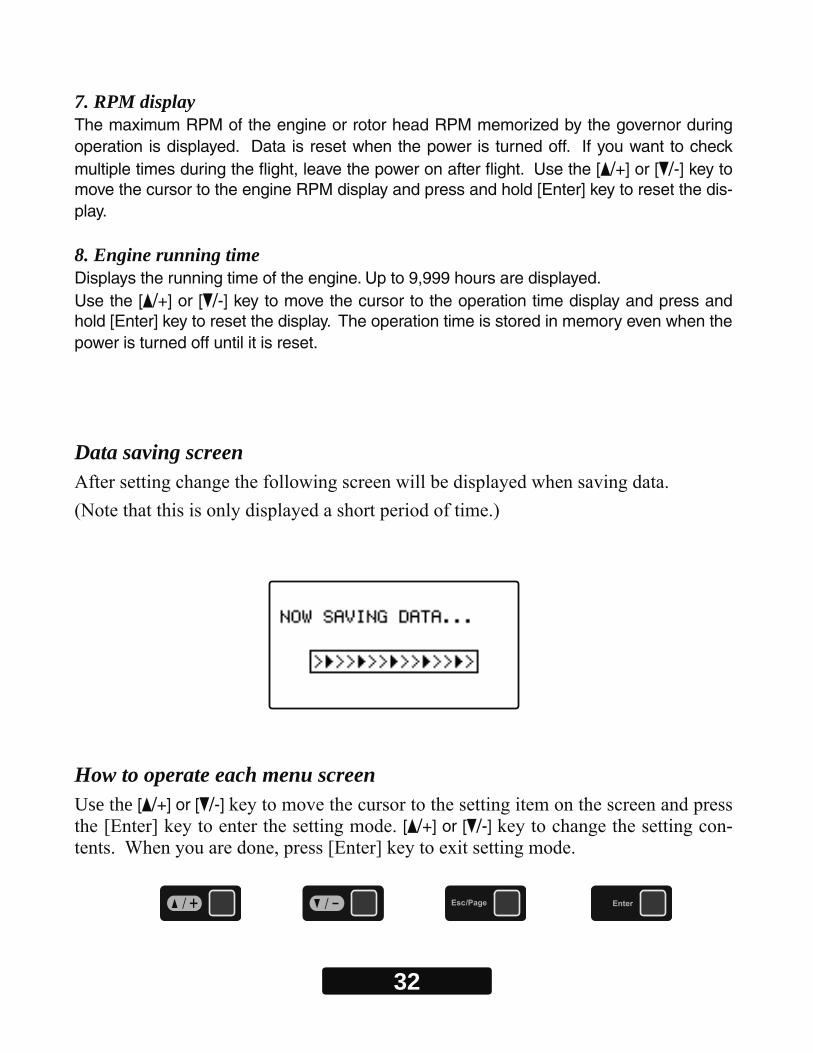
7. RPM display The maximum RPM of the engine or rotor head RPM memorized by the governor during operation is displayed. Data is reset when the power is turned off. If you want to check multiple times during the flight, leave the power on after flight. Use the [ /+] or [ /-] key to move the cursor to the engine RPM display and press and hold [Enter] key to reset the dis-play.
8. Engine running time Displays the running time of the engine. Up to 9,999 hours are displayed.Use the [ /+] or [ /-] key to move the cursor to the operation time display and press and hold [Enter] key to reset the display. The operation time is stored in memory even when the power is turned off until it is reset.
Data saving screen
How to operate each menu screenUse the [ /+] or [ /-]
[ /+] or [ /-] -
33
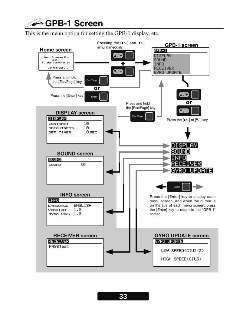
GPB-1 Screen
Home screenGPB-1 screen
DISPLAY screen
SOUND screen
INFO screen
RECEIVER screen GYRO UPDATE screen
Press the [ /+] or [ /-] key
Press the [Enter] key
Press the [Enter] key to display each menu screen, and when the cursor is on the title of each menu screen, press the [Enter] key to return to the "GPB-1" screen.
Press and holdthe [Esc/Page] key
Press and holdthe [Esc/Page] key
Pressing the [ /+] and [ /-] simulataneously
34
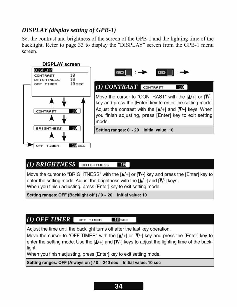
DISPLAY (display setting of GPB-1)
" "
: :
(1) CONTRAST Move the cursor to "CONTRAST" with the [ /+] or [ /-] key and press the [Enter] key to enter the setting mode. Adjust the contrast with the [ /+] and [ /-] keys. When you finish adjusting, press [Enter] key to exit setting mode.
Setting ranges: 0 ~ 20 Initial value: 10
(1) BRIGHTNESS Move the cursor to "BRIGHTNESS" with the [ /+] or [ /-] key and press the [Enter] key to enter the setting mode. Adjust the brightness with the [ /+] and [ /-] keys. When you finish adjusting, press [Enter] key to exit setting mode.
Setting ranges: OFF (Backlight off ) / 0 ~ 20 Initial value: 10
(1) OFF TIMER Adjust the time until the backlight turns off after the last key operation.Move the cursor to "OFF TIMER" with the [ /+] or [ /-] key and press the [Enter] key to enter the setting mode. Use the [ /+] and [ /-] keys to adjust the lighting time of the back-light.When you finish adjusting, press [Enter] key to exit setting mode.
Setting ranges: OFF (Always on ) / 0 ~ 240 sec Initial value: 10 sec
DISPLAY screen

35
SOUND (Key beep sound of GPB-1)-
" "
INFO (Display language and version of GPB-1)-
(1) SOUND Set ON / OFF of key operation sound of GPB-1.Move the cursor to "SOUND" with the [ /+] or [ /-] key and press the [Enter] key to enter the setting mode. Se-lect the ON or OFF of key operation sound with the [ /+] or [ /-] key. When you finish setting, press [Enter] key to exit setting mode.
Setting: ON / OFF Initial setting: ON
(1) LANGUAGE Set the display language of GPB-1.Move the cursor to "LANGUAGE" with the [ /+] or [ /-] key and press the [Enter] key to enter the setting mode. Select the display language with the [ /+] or [ /-] key.When you finish setting, press [Enter] key to exit setting mode.
Setting: ENGLISH / JAPANESE / GERMAN
SOUND screen
INFO screen

36
RECEIVER (Receiver system setting)" " -
page 33 and display the " "
(1) RECEIVER Set the same system as the transmitter to be linked.Move the cursor to the system such as "FASSTest" with the [ /+] or [ /-] key and press the [Enter] key to enter the setting mode. Then select the system with the [/+] or [ /-] key. Since "EXECUTE: Enter (1sec)" is dis-played. Pressing the [Enter] key for about 1 second changes the selected system and exits the setting mode.
Setting: FASSTest- / T-FHSS
RECEIVER screen
FASSTest T-FHSS
Note:
To change the "Receiver System" type, first power off the transmitter and receiver, and re-power the CGY760R while the transmitter is still in the OFF position. The only way to change the receiver type is by power cycling the gyro first.
37
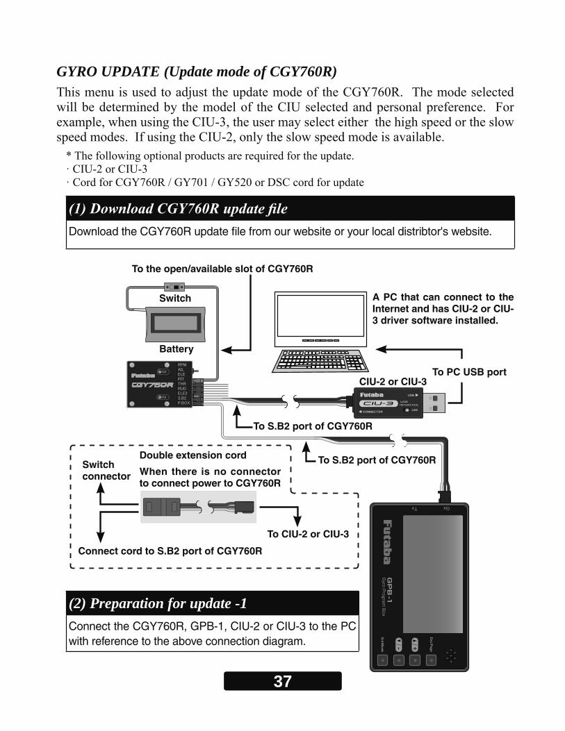
GYRO UPDATE (Update mode of CGY760R)
Download the CGY760R update fi le from our website or your local distribtor's website.
(2) Preparation for update -1 Connect the CGY760R, GPB-1, CIU-2 or CIU-3 to the PC with reference to the above connection diagram.
To the open/available slot of CGY760R
A PC that can connect to the Internet and has CIU-2 or CIU-3 driver software installed.
Double extension cord
When there is no connector to connect power to CGY760R
Switch
Switch connector
Battery
CIU-2 or CIU-3To PC USB port
To CIU-2 or CIU-3
To S.B2 port of CGY760R
Connect cord to S.B2 port of CGY760R
To S.B2 port of CGY760R
38
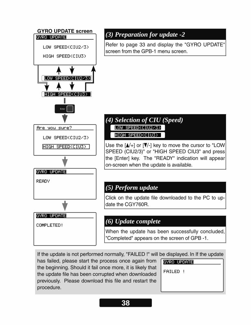
(3) Preparation for update -2 Refer to page 33 and display the "GYRO UPDATE" screen from the GPB-1 menu screen.
(5) Perform updateClick on the update file downloaded to the PC to up-date the CGY760R.
(6) Update completeWhen the update has been successfully concluded, "Completed" appears on the screen of GPB -1.
(4) Selection of CIU (Speed) Use the [ /+] or [ /-] key to move the cursor to "LOW SPEED (CIU2/3)" or "HIGH SPEED CIU3" and press the [Enter] key. The "READY" indication will appear on-screen when the update is available.
If the update is not performed normally, "FAILED !" will be displayed. In If the update has failed, please start the process once again from the beginning. Should it fail once more, it is likely that the update file has been corrupted when downloaded previously. Please download this file and restart the procedure.
GYRO UPDATE screen
39
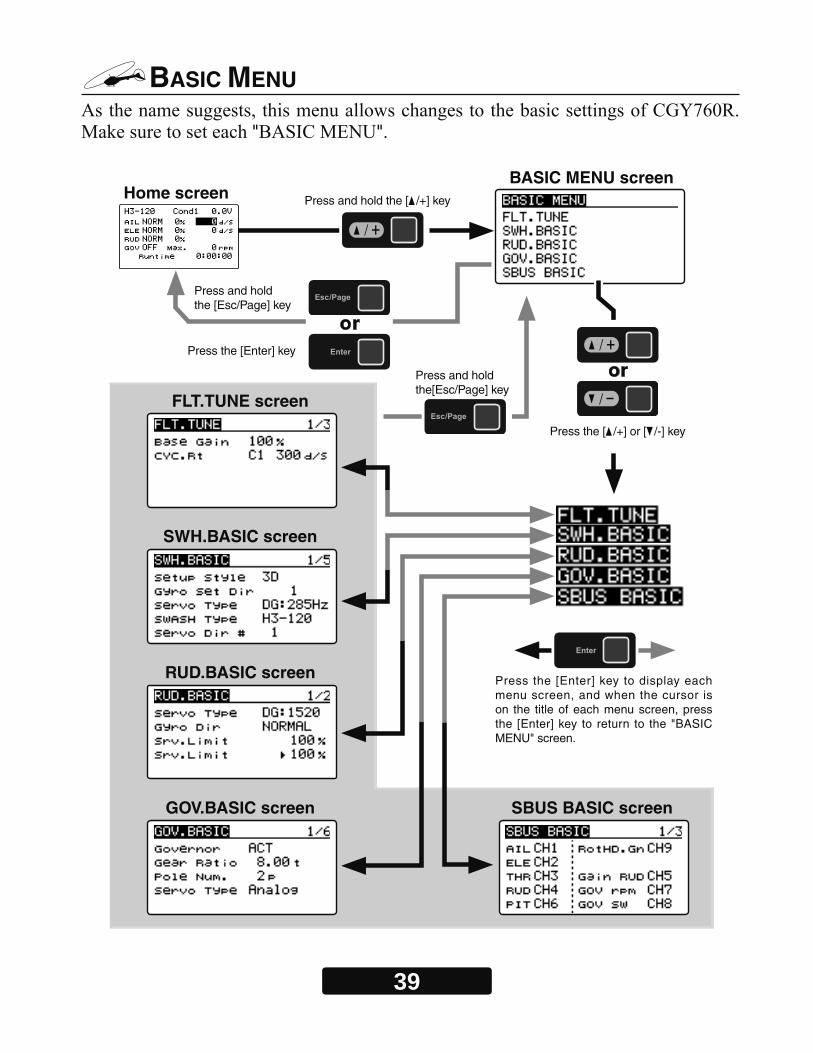
BASIC MENU
" "
Home screenBASIC MENU screen
FLT.TUNE screen
SWH.BASIC screen
RUD.BASIC screen
GOV.BASIC screen SBUS BASIC screen
Press the [ /+] or [ /-] key
Press the [Enter] key
Press the [Enter] key to display each menu screen, and when the cursor is on the title of each menu screen, press the [Enter] key to return to the "BASIC MENU" screen.
Press and holdthe [Esc/Page] key
Press and holdthe[Esc/Page] key
Press and hold the [ /+] key
40
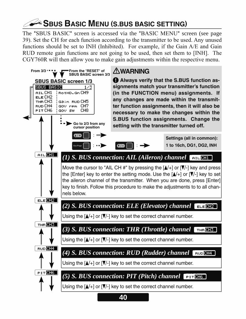
SBUS BASIC MENU (S.BUS BASIC SETTING)The " " screen is accessed via the " " screen (see page
WARNING Always verify that the S.BUS function as-
signments match your transmitter’s function (in the FUNCTION menu) assignments. If any changes are made within the transmit-ter function assignments, then it will also be necessary to make the changes within the S.BUS function assignments. Change the setting with the transmitter turned off.
From 3/3
Go to 2/3 from any cursor position
From the "RESET" of SBUS BASIC screen 3/3
(1) S. BUS connection: AIL (Aileron) channel Move the cursor to "AIL CH #" by pressing the [ /+] or [ /-] key and press the [Enter] key to enter the setting mode. Use the [ /+] or [ /-] key to set the aileron channel of the transmitter. When you are done, press [Enter] key to finish. Follow this procedure to make the adjustments to to all chan-nels below.
(2) S. BUS connection: ELE (Elevator) channel Using the [ /+] or [ /-] key to set the correct channel number.
(3) S. BUS connection: THR (Throttle) channel Using the [ /+] or [ /-] key to set the correct channel number.
(4) S. BUS connection: RUD (Rudder) channel Using the [ /+] or [ /-] key to set the correct channel number.
(5) S. BUS connection: PIT (Pitch) channel Using the [ /+] or [ /-] key to set the correct channel number.
SBUS BASIC screen 1/3
:
: :
Settings (all in common):
1 to 16ch, DG1, DG2, INH
41
From 1/3
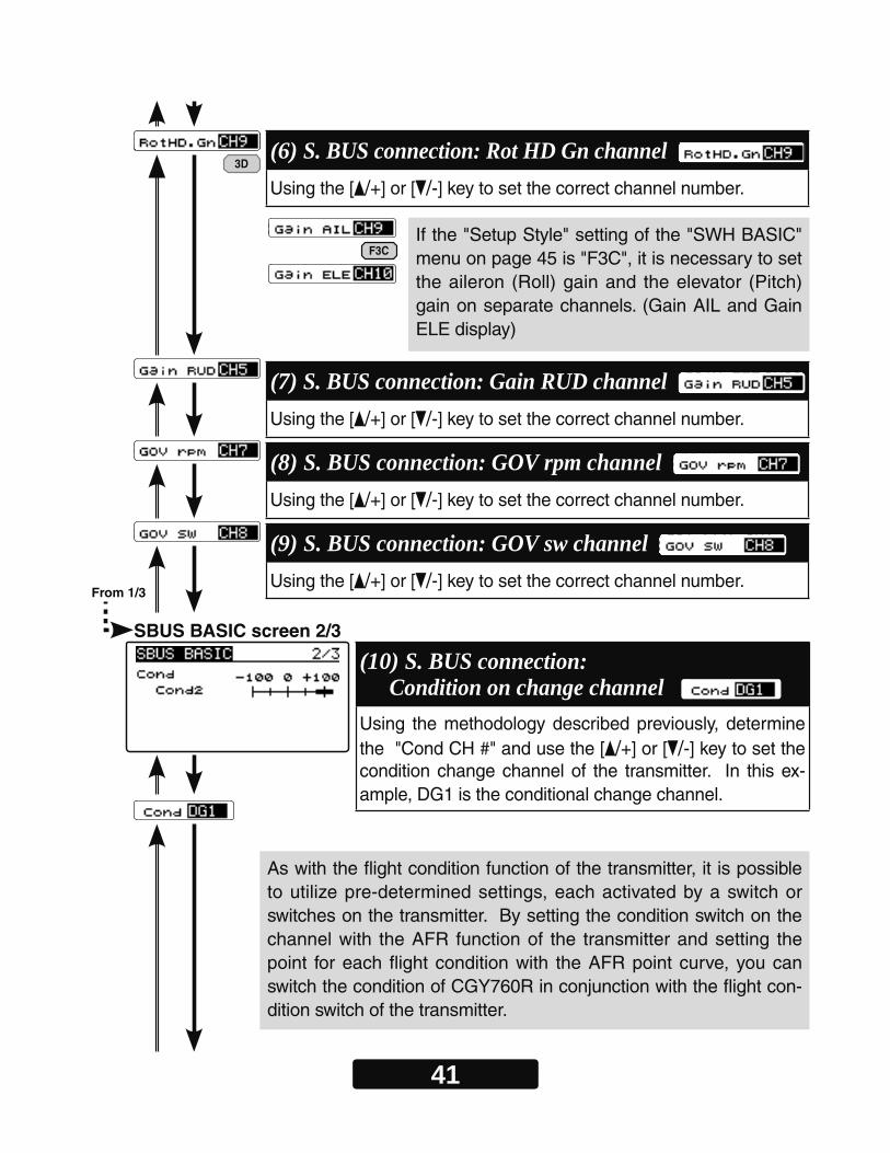
(6) S. BUS connection: Rot HD Gn channel Using the [ /+] or [ /-] key to set the correct channel number.
(7) S. BUS connection: Gain RUD channel Using the [ /+] or [ /-] key to set the correct channel number.
(8) S. BUS connection: GOV rpm channel Using the [ /+] or [ /-] key to set the correct channel number.
(9) S. BUS connection: GOV sw channel Using the [ /+] or [ /-] key to set the correct channel number.
(10) S. BUS connection: Condition on change channel
Using the methodology described previously, determine the "Cond CH #" and use the [ /+] or [ /-] key to set the condition change channel of the transmitter. In this ex-ample, DG1 is the conditional change channel.
SBUS BASIC screen 2/3
As with the flight condition function of the transmitter, it is possible to utilize pre-determined settings, each activated by a switch or switches on the transmitter. By setting the condition switch on the channel with the AFR function of the transmitter and setting the point for each flight condition with the AFR point curve, you can switch the condition of CGY760R in conjunction with the flight con-dition switch of the transmitter.
If the "Setup Style" setting of the "SWH BASIC" menu on page 45 is "F3C", it is necessary to set the aileron (Roll) gain and the elevator (Pitch) gain on separate channels. (Gain AIL and Gain ELE display)
F3C
3D
42
From 2/3
Go to 1/3 from any cursor position
Go to the menu title of SBUS BASIC screen 1/3
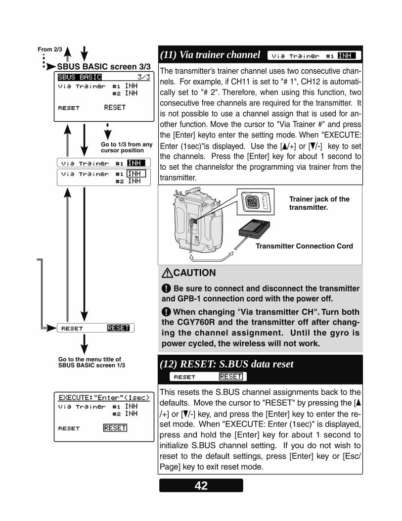
SBUS BASIC screen 3/3(11) Via trainer channel The transmitter’s trainer channel uses two consecutive chan-nels. For example, if CH11 is set to "# 1", CH12 is automati-cally set to "# 2". Therefore, when using this function, two consecutive free channels are required for the transmitter. It is not possible to use a channel assign that is used for an-other function. Move the cursor to "Via Trainer #" and press the [Enter] keyto enter the setting mode. When "EXECUTE: Enter (1sec)"is displayed. Use the [ /+] or [ /-] key to set the channels. Press the [Enter] key for about 1 second to to set the channelsfor the programming via trainer from the transmitter.
(12) RESET: S.BUS data reset This resets the S.BUS channel assignments back to the defaults. Move the cursor to "RESET" by pressing the [/+] or [ /-] key, and press the [Enter] key to enter the re-set mode. When "EXECUTE: Enter (1sec)" is displayed, press and hold the [Enter] key for about 1 second to initialize S.BUS channel setting. If you do not wish to reset to the default settings, press [Enter] key or [Esc/Page] key to exit reset mode.
Transmitter Connection Cord
Trainer jack of the transmitter.
CAUTION
Be sure to connect and disconnect the transmitter and GPB-1 connection cord with the power off.
When changing "Via transmitter CH". Turn both the CGY760R and the transmitter off after chang-ing the channel assignment. Until the gyro is power cycled, the wireless will not work.

43
About Transfer Function Of Gyro Setting Data-
Setting on transmitter side1. Follow the transmitter’s instruction manual, to set these items to the correct configu-
ration. Use the TX's Function menu to set two consecutive free AUX channels to match the channel assignments set in the gyro SBUS menu. However, do not set
the "Control" and "Trim" functions.
2. Set the two free channels to the following settings.Sub Trim: 0 / Fail safe: hold)/ Battery fail safe: OFF / Set the end point: 100The limit point:155 (maximum) / Servo speed: 0 / Servo Reverse: Normal
3. Set the trainer function as follows according to the transmitter’s instruction manual.Always ONTeacher / Student: ----------------------------------------------------------------------Teacher Channel mode: -----------------------------------------------------------------------------16CHMode for individual channels being used for gyro programming: ---------- NormalRate: -------------------------------------------------------------------------------------------- 100
Point : In 12ch FASSTest mode only the first 12 channels can be used for wireless trainer. In 18ch FASSTest it is possible to use 18chs.
Upon turning the transmitter " "
Note:
Opening screen ID screen
Via Trainer screenHome screen
Press and holdthe[Esc/Page] key
Press and holdthe[Esc/Page] key
Press and holdthe[Esc/Page] key
Press and holdthe[Eter] key
Press the [Enter] key with the cursor on the "Via Trainer"
44
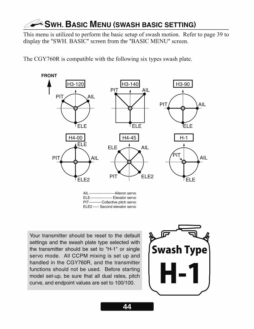
SWH. BASIC MENU (SWASH BASIC SETTING)
display the " " screen from the " "
ELE
PIT AIL
H3-120
ELE
PIT AILH3-140
ELE
PIT AIL
H3-90
ELE2
ELE
PIT AIL
H4-00
ELE2
FRONT
ELE
PIT
AIL
H4-45
ELE
PIT AIL
H-1
H-1Swash Type
Your transmitter should be reset to the default settings and the swash plate type selected with the transmitter should be set to "H-1" or single servo mode. All CCPM mixing is set up and handled in the CGY760R, and the transmitter functions should not be used. Before starting model set-up, be sure that all dual rates, pitch curve, and endpoint values are set to 100/100.
AIL ---------------------Aileron servoELE ------------------ Elevator servoPIT ----------Collective pitch servoELE2 ----- Second elevator servo

45
WARNING
Do not connect the servo to the gy-ros until you select the servo type in the "SWH. BASIC" menu. *If the servo type is incorrect, it is possible to damage the servos or CGY760R.
SWH. BASIC screen 1/5
From 5/5 From the "Pit.Low" of SWH. BASIC screen 5/5
Go to 2/5 from any cursor position : :
:
(1) Setup style 3D mode contains a proven set of parameters which are good for not only 3D but also F3C flying. F3C Mode is for unique or special tuning types only.*The changed menu is indicated on a map.*When the style is changed, setting of AIL/ELE/RUD is re-initialized and defaults are changed.Move the cursor to "Setup style" by pressing the [ /+] or [ /-] key and press the [Enter] key to enter the setting mode. Use the [ /+] or [ /-] key to set the style. When "EXECUTE: Enter (1sec)" is displayed. Press the [Enter] key for about 1 second to changes the selected style. The program will also exit the setting mode accordingly.
(2) Gyro Set Dir: Mounting direction Set the roll axis, pitch axis, yaw axis according to the mounting direction of CGY 760R. Set mounting direction with reference to page 18 - 19. Move the cursor to "Gyro Set Dir" by pressing the [ /+] or [ /-] key and press the [Enter] key to enter the mounting direction. Then select the mounting direc-tion # with the [ /+] or [ /-] key. When you finish setting, press [Enter] key to exit setting mode. When the LED on the Gx side finishes blinking, please turn the power off and on again to confirm that it is working properly.
Setting: 1 ~ 6 Initial setting: 1
WARNING If you do not turn the power back on after changing "Gyro Set Dir", the gyro-scope will not operate properly, there is a risk of crashing.
46
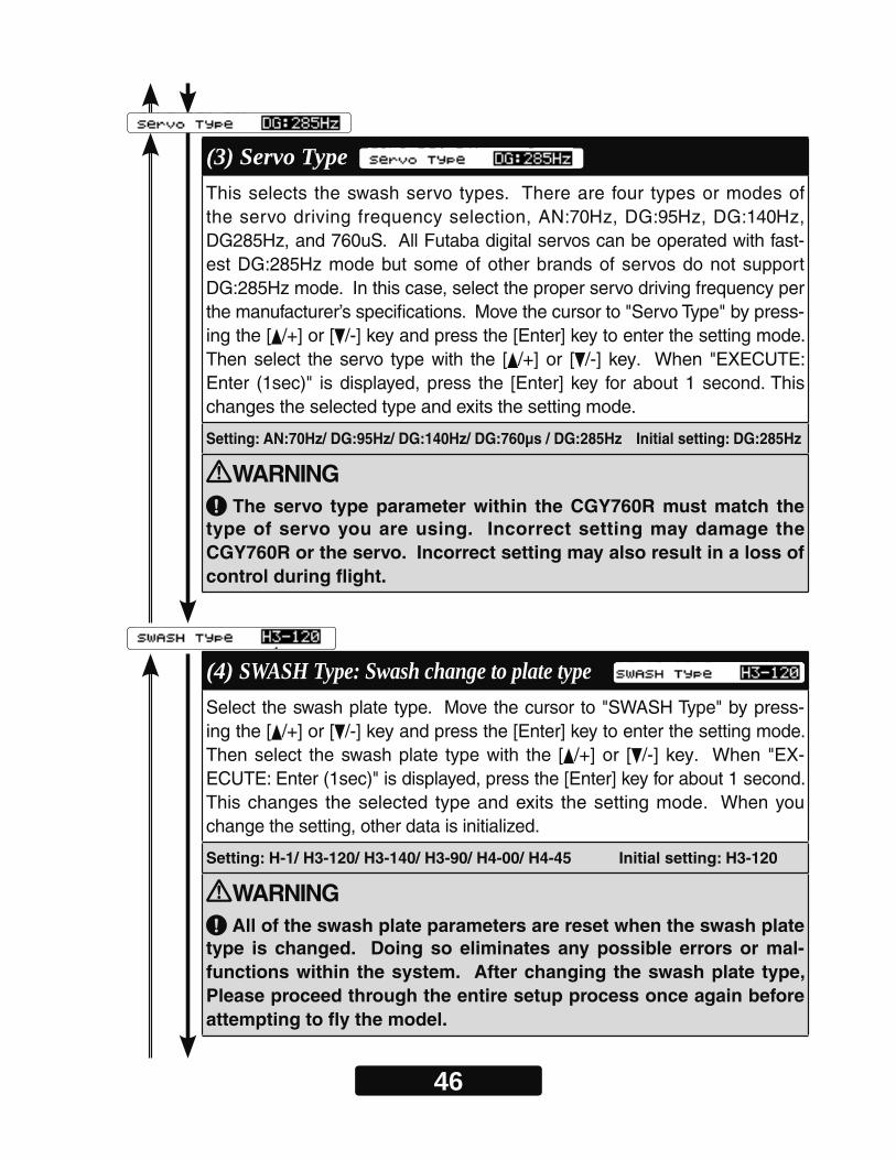
(3) Servo Type This selects the swash servo types. There are four types or modes of the servo driving frequency selection, AN:70Hz, DG:95Hz, DG:140Hz, DG285Hz, and 760uS. All Futaba digital servos can be operated with fast-est DG:285Hz mode but some of other brands of servos do not support DG:285Hz mode. In this case, select the proper servo driving frequency per the manufacturer’s specifications. Move the cursor to "Servo Type" by press-ing the [ /+] or [ /-] key and press the [Enter] key to enter the setting mode. Then select the servo type with the [ /+] or [ /-] key. When "EXECUTE: Enter (1sec)" is displayed, press the [Enter] key for about 1 second. This changes the selected type and exits the setting mode.
Setting: AN:70Hz/ DG:95Hz/ DG:140Hz/ DG:760μs / DG:285Hz Initial setting: DG:285Hz
WARNING The servo type parameter within the CGY760R must match the
type of servo you are using. Incorrect setting may damage the CGY760R or the servo. Incorrect setting may also result in a loss of control during flight.
(4) SWASH Type: Swash change to plate type Select the swash plate type. Move the cursor to "SWASH Type" by press-ing the [ /+] or [ /-] key and press the [Enter] key to enter the setting mode. Then select the swash plate type with the [ /+] or [ /-] key. When "EX-ECUTE: Enter (1sec)" is displayed, press the [Enter] key for about 1 second. This changes the selected type and exits the setting mode. When you change the setting, other data is initialized.
Setting: H-1/ H3-120/ H3-140/ H3-90/ H4-00/ H4-45 Initial setting: H3-120
WARNING All of the swash plate parameters are reset when the swash plate
type is changed. Doing so eliminates any possible errors or mal-functions within the system. After changing the swash plate type, Please proceed through the entire setup process once again before attempting to fly the model.
47
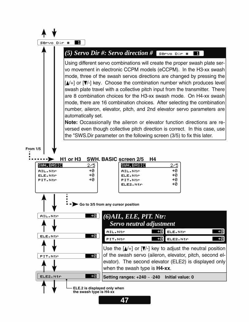
(5) Servo Dir #: Servo direction # Using different servo combinations will create the proper swash plate ser-vo movement in electronic CCPM models (eCCPM). In the H3-xx swash mode, three of the swash servos directions are changed by pressing the [ /+] or [ /-] key. Choose the combination number which produces level swash plate travel with a collective pitch input from the transmitter. There are 8 combination choices for the H3-xx swash mode. On H4-xx swash mode, there are 16 combination choices. After selecting the combination number, aileron, elevator, pitch, and 2nd elevator servo parameters are automatically set.Note: Occassionally the aileron or elevator function directions are re-versed even though collective pitch direction is correct. In this case, use the "SWS.Dir parameter on the following screen (3/5) to fi x this later.
From 1/5
H1 or H3 SWH. BASIC screen 2/5 H4
Go to 3/5 from any cursor position
ELE.2 is displayed only when the swash type is H4-xx
(6)AIL, ELE, PIT. Ntr: Servo neutral adjustment Use the [ /+] or [ /-] key to adjust the neutral position of the swash servo (aileron, elevator, pitch, second el-evator). The second elevator (ELE2) is displayed only when the swash type is H4-xx.
Setting ranges: +240 ~ -240 Initial value: 0
48
SWH. BASIC screen 3/5
Cond
From 2/5
Go to 4/5 from any cursor position
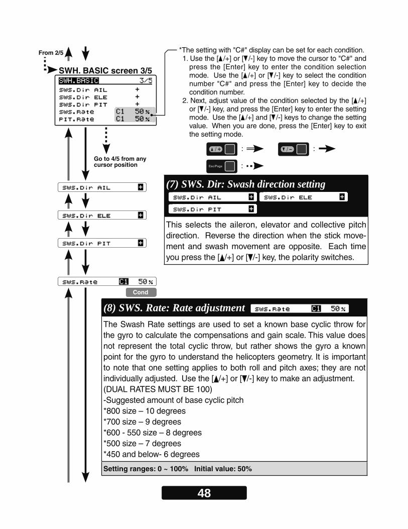
*The setting with "C#" display can be set for each condition.1. Use the [ /+] or [ /-] key to move the cursor to "C#" and
press the [Enter] key to enter the condition selection mode. Use the [ /+] or [ /-] key to select the condition number "C#" and press the [Enter] key to decide the condition number.
2. Next, adjust value of the condition selected by the [ /+] or [ /-] key, and press the [Enter] key to enter the setting mode. Use the [ /+] and [ /-] keys to change the setting value. When you are done, press the [Enter] key to exit the setting mode.
: :
:
(7) SWS. Dir: Swash direction setting This selects the aileron, elevator and collective pitch direction. Reverse the direction when the stick move-ment and swash movement are opposite. Each time you press the [ /+] or [ /-] key, the polarity switches.
(8) SWS. Rate: Rate adjustment The Swash Rate settings are used to set a known base cyclic throw for the gyro to calculate the compensations and gain scale. This value does not represent the total cyclic throw, but rather shows the gyro a known point for the gyro to understand the helicopters geometry. It is important to note that one setting applies to both roll and pitch axes; they are not individually adjusted. Use the [ /+] or [ /-] key to make an adjustment.(DUAL RATES MUST BE 100) -Suggested amount of base cyclic pitch*800 size – 10 degrees*700 size – 9 degrees*600 - 550 size – 8 degrees*500 size – 7 degrees*450 and below- 6 degrees
Setting ranges: 0 ~ 100% Initial value: 50%
49
Cond
From 3/5
Go to 5/5 from any cursor position
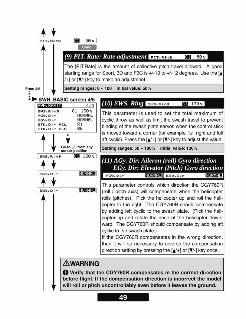
(9) PIT. Rate: Rate adjustment The [PIT.Rate] is the amount of collective pitch travel allowed. A good starting range for Sport, 3D and F3C is +/-10 to +/-12 degrees. Use the [/+] or [ /-] key to make an adjustment.
Setting ranges: 0 ~ 100 Initial value: 50%
(10) SWS. Ring This parameter is used to set the total maximum of cyclic throw as well as limit the swash travel to prevent binding of the swash plate servos when the control stick is moved toward a corner (for example, full right and full aft cyclic). Press the [ /+] or [ /-] key to adjust the value.
Setting ranges: 50 ~ 100% Initial value: 130%
(11) AGy. Dir: Aileron (roll) Gyro directionEGy. Dir: Elevator (Pitch) Gyro direction
This parameter controls which direction the CGY760R (roll / pitch axis) will compensate when the helicopter rolls (pitches). Pick the helicopter up and roll the heli-copter to the right. The CGY760R should compensate by adding left cyclic to the swash plate. (Pick the heli-copter up and rotate the nose of the helicopter down-ward. The CGY760R should compensate by adding aft cyclic to the swash plate.) If the CGY760R compensates in the wrong direction, then it will be necessary to reverse the compensation direction setting by pressing the [ /+] or [ /-] key once.
SWH. BASIC screen 4/5
WARNING Verify that the CGY760R compensates in the correct direction
before flight. If the compensation direction is incorrect the model will roll or pitch uncontrollably even before it leaves the ground.
50
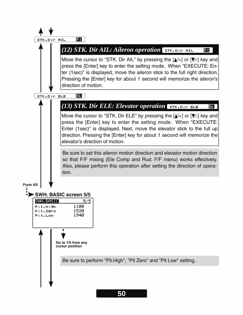
(13) STK. Dir ELE: Elevator operation Move the cursor to "STK. Dir ELE" by pressing the [ /+] or [ /-] key and press the [Enter] key to enter the setting mode. When "EXECUTE: Enter (1sec)" is displayed. Next, move the elevator stick to the full up direction. Pressing the [Enter] key for about 1 second will memorize the elevator’s direction of motion.
(12) STK. Dir AIL: Aileron operation Move the cursor to "STK. Dir AIL" by pressing the [ /+] or [ /-] key and press the [Enter] key to enter the setting mode. When "EXECUTE: En-ter (1sec)" is displayed, move the aileron stick to the full right direction. Pressing the [Enter] key for about 1 second will memorize the aileron’s direction of motion.
Be sure to set this aileron motion direction and elevator motion direction so that F/F mixing (Ele Comp and Rud. F/F menu) works effectively. Also, please perform this operation after setting the direction of opera-tion.
Be sure to perform "Pit.High", "Pit Zero" and "Pit Low" setting.
From 4/5
Go to 1/5 from any cursor position
SWH. BASIC screen 5/5
51
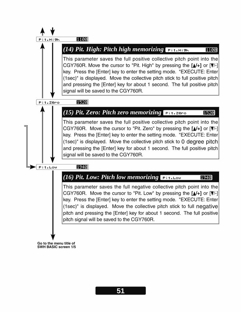
(14) Pit. High: Pitch high memorizing This parameter saves the full positive collective pitch point into the CGY760R. Move the cursor to "Pit. High" by pressing the [ /+] or [ /-] key. Press the [Enter] key to enter the setting mode. "EXECUTE: Enter (1sec)" is displayed. Move the collective pitch stick to full positive pitch and pressing the [Enter] key for about 1 second. The full positive pitch signal will be saved to the CGY760R.
(15) Pit. Zero: Pitch zero memorizing This parameter saves the full positive collective pitch point into the CGY760R. Move the cursor to "Pit. Zero" by pressing the [ /+] or [ /-] key. Press the [Enter] key to enter the setting mode. "EXECUTE: Enter (1sec)" is displayed. Move the collective pitch stick to 0 degree pitch and pressing the [Enter] key for about 1 second. The full positive pitch signal will be saved to the CGY760R.
(16) Pit. Low: Pitch low memorizing This parameter saves the full negative collective pitch point into the CGY760R. Move the cursor to "Pit. Low" by pressing the [ /+] or [ /-] key. Press the [Enter] key to enter the setting mode. "EXECUTE: Enter (1sec)" is displayed. Move the collective pitch stick to full negative pitch and pressing the [Enter] key for about 1 second. The full positive pitch signal will be saved to the CGY760R.
Go to the menu title of SWH BASIC screen 1/5
52
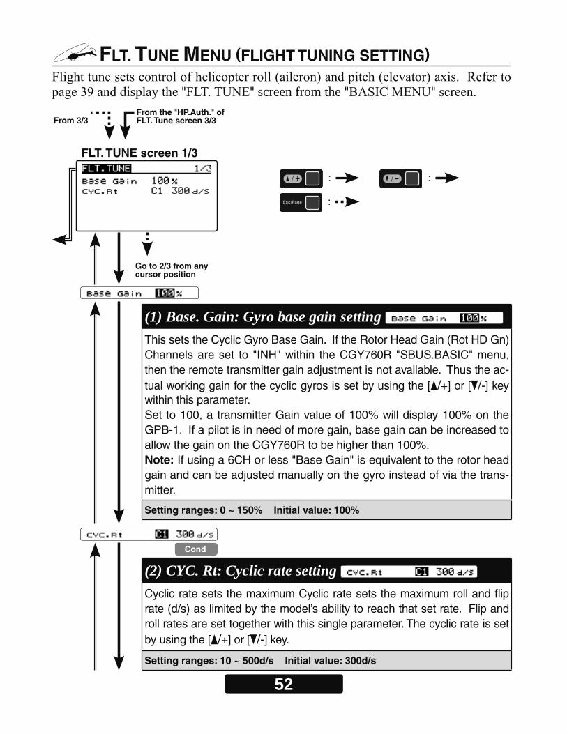
FLT. TUNE MENU (FLIGHT TUNING SETTING)
" " screen from the " "
FLT. TUNE screen 1/3
From 3/3From the "HP.Auth." of FLT. Tune screen 3/3
(1) Base. Gain: Gyro base gain setting This sets the Cyclic Gyro Base Gain. If the Rotor Head Gain (Rot HD Gn) Channels are set to "INH" within the CGY760R "SBUS.BASIC" menu, then the remote transmitter gain adjustment is not available. Thus the ac-tual working gain for the cyclic gyros is set by using the [ /+] or [ /-] key within this parameter.Set to 100, a transmitter Gain value of 100% will display 100% on the GPB-1. If a pilot is in need of more gain, base gain can be increased to allow the gain on the CGY760R to be higher than 100%. Note: If using a 6CH or less "Base Gain" is equivalent to the rotor head gain and can be adjusted manually on the gyro instead of via the trans-mitter.
Setting ranges: 0 ~ 150% Initial value: 100%
(2) CYC. Rt: Cyclic rate setting Cyclic rate sets the maximum Cyclic rate sets the maximum roll and flip rate (d/s) as limited by the model’s ability to reach that set rate. Flip and roll rates are set together with this single parameter. The cyclic rate is set by using the [ /+] or [ /-] key.
Setting ranges: 10 ~ 500d/s Initial value: 300d/s
Go to 2/3 from any cursor position
Cond
: :
:
53
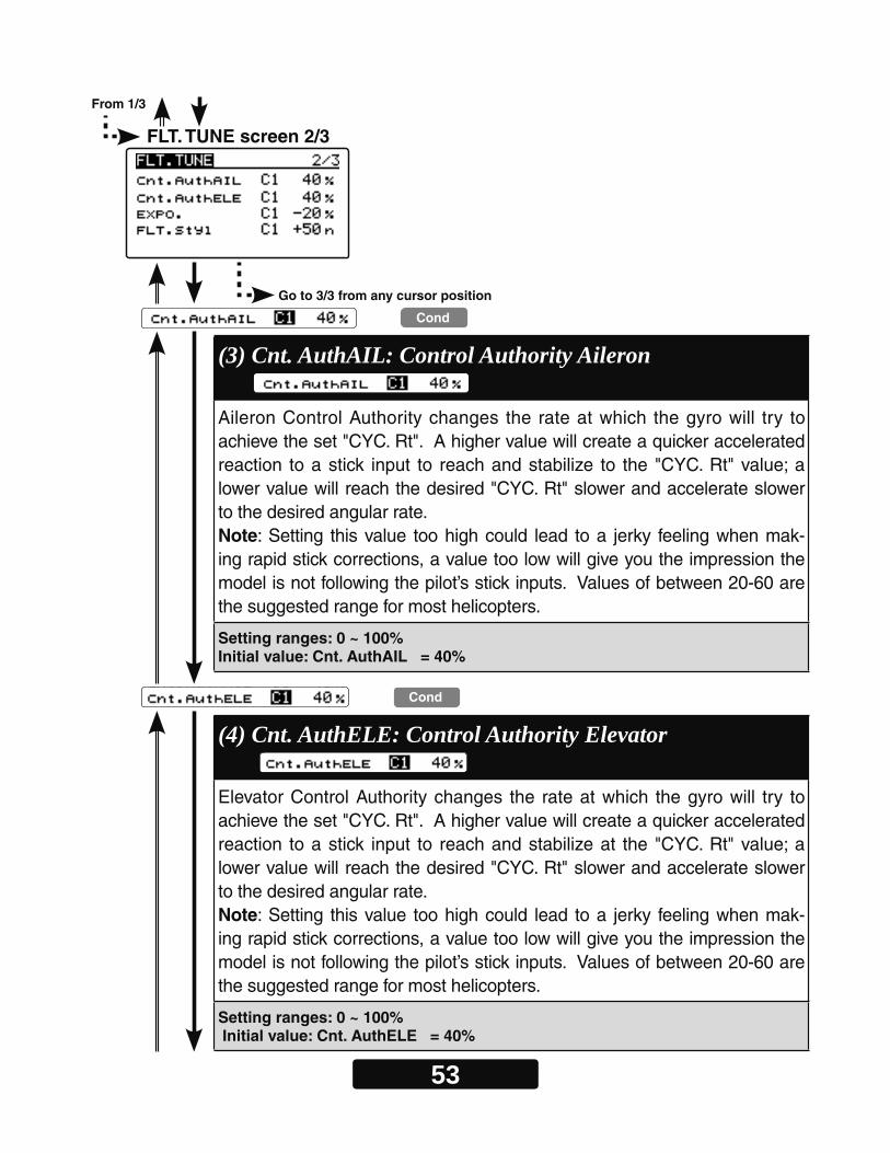
FLT. TUNE screen 2/3
Cond
(3) Cnt. AuthAIL: Control Authority Aileron Aileron Control Authority changes the rate at which the gyro will try to achieve the set "CYC. Rt". A higher value will create a quicker accelerated reaction to a stick input to reach and stabilize to the "CYC. Rt" value; a lower value will reach the desired "CYC. Rt" slower and accelerate slower to the desired angular rate. Note: Setting this value too high could lead to a jerky feeling when mak-ing rapid stick corrections, a value too low will give you the impression the model is not following the pilot’s stick inputs. Values of between 20-60 are the suggested range for most helicopters.
Setting ranges: 0 ~ 100% Initial value: Cnt. AuthAIL = 40%
(4) Cnt. AuthELE: Control Authority Elevator Elevator Control Authority changes the rate at which the gyro will try to achieve the set "CYC. Rt". A higher value will create a quicker accelerated reaction to a stick input to reach and stabilize at the "CYC. Rt" value; a lower value will reach the desired "CYC. Rt" slower and accelerate slower to the desired angular rate. Note: Setting this value too high could lead to a jerky feeling when mak-ing rapid stick corrections, a value too low will give you the impression the model is not following the pilot’s stick inputs. Values of between 20-60 are the suggested range for most helicopters.
Setting ranges: 0 ~ 100% Initial value: Cnt. AuthELE = 40%
Cond
Go to 3/3 from any cursor position
From 1/3

54
Cond
(5) EXPO.: Exponential Tune the exponential as desired to change the feel of the cyclic controls around center stick. Negative values soften control feel; Positive values increase sensitivity. The exponential rate is set by using the [ /+] or [ /-] key.Note: that any exponential present in the TRANSMITTER adds to the value set in the CGY760R.
Setting ranges: -100 ~ 0 ~ +100% Initial value: -20%
(6) FLT. Styl: Flight style Increasing this value will create a more robotic reaction to the stick, leav-ing the pilot with the impression that the model is locked into in a position after an input. It will also tend to have a more calculated feeling when making inputs.-Lowering the value will make the model feel more fluid and easy to rotate with the stick input. The model will feel a little more lively during faster cy-clic movements and direction changes. Set by using the [ /+] or [ /-] key.
Setting ranges: FLT. Styl 3D = 0 ~ 100n Initial value: FLT. Styl 3D = 50n
Cond
FLT. TUNE screen 3/3
Note: To effectively operate the next "ELE Comp" (elevator correction), make sure to set "Pit High", "Pit Zero", "Pit Low" on the "SWITCH BASIC" menu on page 51.
From 2/3
Go to 1/3 from any cursor position
55
Go to the menu title of FLT. TUNE screen 1/3
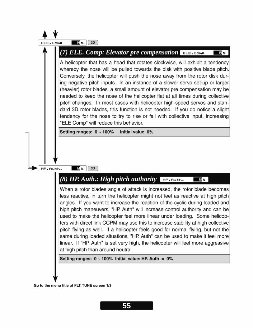
(7) ELE. Comp: Elevator pre compensation A helicopter that has a head that rotates clockwise, will exhibit a tendency whereby the nose will be pulled towards the disk with positive blade pitch. Conversely, the helicopter will push the nose away from the rotor disk dur-ing negative pitch inputs. In an instance of a slower servo set-up or larger (heavier) rotor blades, a small amount of elevator pre compensation may be needed to keep the nose of the helicopter flat at all times during collective pitch changes. In most cases with helicopter high-speed servos and stan-dard 3D rotor blades, this function is not needed. If you do notice a slight tendency for the nose to try to rise or fall with collective input, increasing "ELE Comp" will reduce this behavior.
Setting ranges: 0 ~ 100% Initial value: 0%
(8) HP. Auth.: High pitch authority When a rotor blades angle of attack is increased, the rotor blade becomes less reactive, in turn the helicopter might not feel as reactive at high pitch angles. If you want to increase the reaction of the cyclic during loaded and high pitch maneuvers, "HP. Auth" will increase control authority and can be used to make the helicopter feel more linear under loading. Some helicop-ters with direct link CCPM may use this to increase stability at high collective pitch flying as well. If a helicopter feels good for normal flying, but not the same during loaded situations, "HP. Auth" can be used to make it feel more linear. If "HP. Auth" is set very high, the helicopter will feel more aggressive at high pitch than around neutral.
Setting ranges: 0 ~ 100% Initial value: HP. Auth = 0%
3D
3D
56
RUD. BASIC MENU (RUDDER GYRO BASIC SETTING)
" "" " screen from the " "
Setting on transmitter side
1. Enable rudder gyro mixing.
2. In the gyro mode select "GY".
3. Temporarily set the gyro sensitivity of normal condition and hold condition to AVCS 75%. Also, temporarily set the gyro sensitivity of all idle up conditions to AVCS 50%.
4. Set the channel angle setting function (ATV / AFR / EPA) of the rudder channel and sensitivity setting channel to 100%.
5. Temporarily set the D/R function of the rudder channel to 75% both left and right.
6. We recommend that you temporarily set the EXP function of the rudder channel to about -30% (mild side 30%) need to clarify what is meant by mild side.
WARNING
Do not connect the tail rotor servo to the gyro until the servo type has been selected. Operating the servo using the incorrect setting may damage the CGY760R or the servo.
Do not operate with the linkage connected until the "Srv. Limit" function correctly sets the servo limit point. If the servo operates be-yond the linkage operating range, there is a danger of either the servo or helicopter being damaged.
-
57
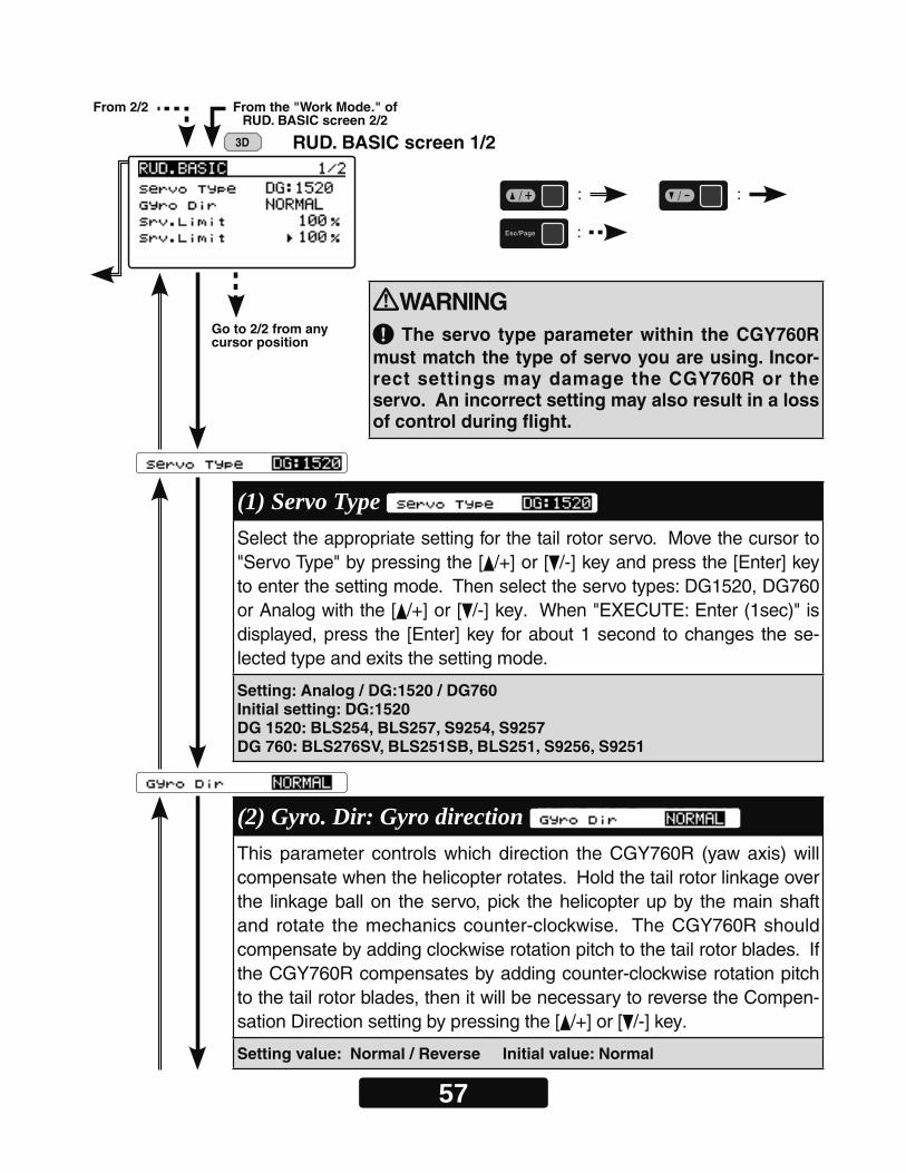
RUD. BASIC screen 1/2
(1) Servo Type Select the appropriate setting for the tail rotor servo. Move the cursor to "Servo Type" by pressing the [ /+] or [ /-] key and press the [Enter] key to enter the setting mode. Then select the servo types: DG1520, DG760 or Analog with the [ /+] or [ /-] key. When "EXECUTE: Enter (1sec)" is displayed, press the [Enter] key for about 1 second to changes the se-lected type and exits the setting mode.
Setting: Analog / DG:1520 / DG760Initial setting: DG:1520DG 1520: BLS254, BLS257, S9254, S9257DG 760: BLS276SV, BLS251SB, BLS251, S9256, S9251
WARNING The servo type parameter within the CGY760R
must match the type of servo you are using. Incor-rect settings may damage the CGY760R or the servo. An incorrect setting may also result in a loss of control during flight.
From 2/2 From the "Work Mode." of RUD. BASIC screen 2/2
Go to 2/2 from any cursor position
(2) Gyro. Dir: Gyro direction This parameter controls which direction the CGY760R (yaw axis) will compensate when the helicopter rotates. Hold the tail rotor linkage over the linkage ball on the servo, pick the helicopter up by the main shaft and rotate the mechanics counter-clockwise. The CGY760R should compensate by adding clockwise rotation pitch to the tail rotor blades. If the CGY760R compensates by adding counter-clockwise rotation pitch to the tail rotor blades, then it will be necessary to reverse the Compen-sation Direction setting by pressing the [ /+] or [ /-] key.
Setting value: Normal / Reverse Initial value: Normal
3D
: :
:
58
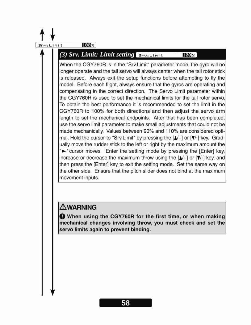
(3) Srv. Limit: Limit setting When the CGY760R is in the "Srv.Limit" parameter mode, the gyro will no longer operate and the tail servo will always center when the tail rotor stick is released. Always exit the setup functions before attempting to fly the model. Before each flight, always ensure that the gyros are operating and compensating in the correct direction. The Servo Limit parameter within the CGY760R is used to set the mechanical limits for the tail rotor servo. To obtain the best performance it is recommended to set the limit in the CGY760R to 100% for both directions and then adjust the servo arm length to set the mechanical endpoints. After that has been completed, use the servo limit parameter to make small adjustments that could not be made mechanically. Values between 90% and 110% are considered opti-mal. Hold the cursor to "Srv.Limit" by pressing the [ /+] or [ /-] key. Grad-ually move the rudder stick to the left or right by the maximum amount the " "cursor moves. Enter the setting mode by pressing the [Enter] key, increase or decrease the maximum throw using the [ /+] or [ /-] key, and then press the [Enter] key to exit the setting mode. Set the same way on the other side. Ensure that the pitch slider does not bind at the maximum movement inputs.
WARNING When using the CGY760R for the first time, or when making
mechanical changes involving throw, you must check and set the servo limits again to prevent binding.
59
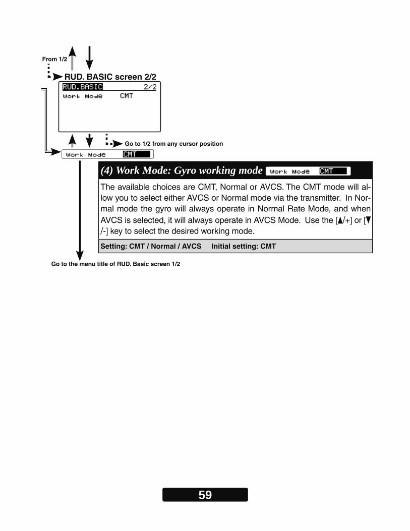
RUD. BASIC screen 2/2
Go to the menu title of RUD. Basic screen 1/2
(4) Work Mode: Gyro working mode The available choices are CMT, Normal or AVCS. The CMT mode will al-low you to select either AVCS or Normal mode via the transmitter. In Nor-mal mode the gyro will always operate in Normal Rate Mode, and when AVCS is selected, it will always operate in AVCS Mode. Use the [ /+] or [/-] key to select the desired working mode.
Setting: CMT / Normal / AVCS Initial setting: CMT
From 1/2
Go to 1/2 from any cursor position
60
GOV. BASIC MENU (GOVERNOR BASIC SETTING)
" " screen from the " "
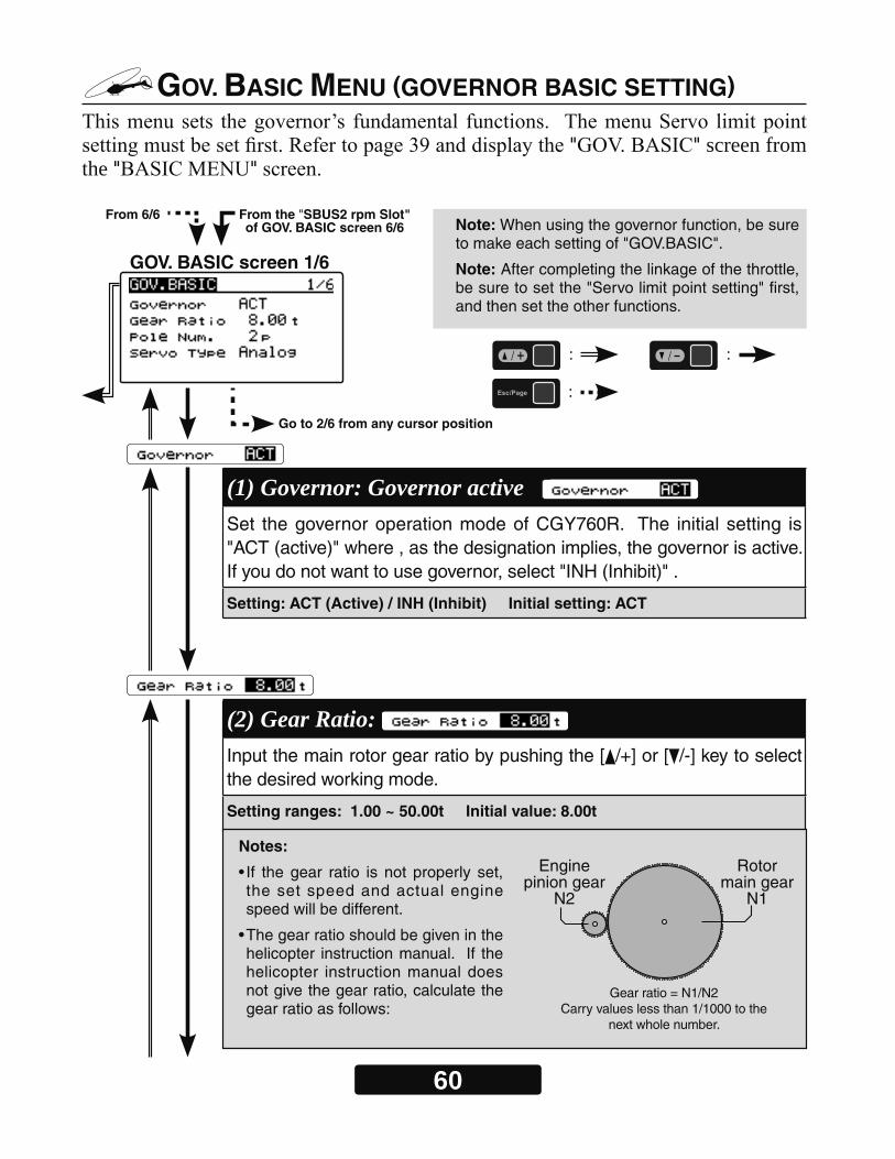
GOV. BASIC screen 1/6
From 6/6 From the "SBUS2 rpm Slot" of GOV. BASIC screen 6/6 Note: When using the governor function, be sure
to make each setting of "GOV.BASIC".
Note: After completing the linkage of the throttle, be sure to set the "Servo limit point setting" first, and then set the other functions.
: :
:
Go to 2/6 from any cursor position
(1) Governor: Governor active Set the governor operation mode of CGY760R. The initial setting is "ACT (active)" where , as the designation implies, the governor is active. If you do not want to use governor, select "INH (Inhibit)" .
Setting: ACT (Active) / INH (Inhibit) Initial setting: ACT
(2) Gear Ratio: Input the main rotor gear ratio by pushing the [ /+] or [ /-] key to select the desired working mode.
Setting ranges: 1.00 ~ 50.00t Initial value: 8.00t
Notes:
• If the gear ratio is not properly set, the set speed and actual engine speed will be different.
• The gear ratio should be given in the helicopter instruction manual. If the helicopter instruction manual does not give the gear ratio, calculate the gear ratio as follows:
Rotormain gear
N1
Enginepinion gear
N2
Gear ratio = N1/N2 Carry values less than 1/1000 to the
next whole number.
61
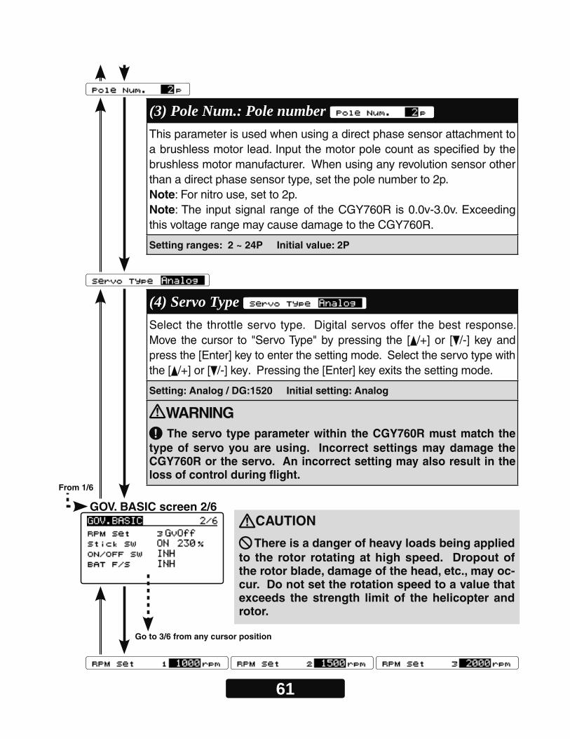
GOV. BASIC screen 2/6
Go to 3/6 from any cursor position
(3) Pole Num.: Pole number This parameter is used when using a direct phase sensor attachment to a brushless motor lead. Input the motor pole count as specified by the brushless motor manufacturer. When using any revolution sensor other than a direct phase sensor type, set the pole number to 2p.Note: For nitro use, set to 2p. Note: The input signal range of the CGY760R is 0.0v-3.0v. Exceeding this voltage range may cause damage to the CGY760R.
Setting ranges: 2 ~ 24P Initial value: 2P
(4) Servo Type Select the throttle servo type. Digital servos offer the best response. Move the cursor to "Servo Type" by pressing the [ /+] or [ /-] key and press the [Enter] key to enter the setting mode. Select the servo type with the [ /+] or [ /-] key. Pressing the [Enter] key exits the setting mode.
Setting: Analog / DG:1520 Initial setting: Analog
WARNING The servo type parameter within the CGY760R must match the
type of servo you are using. Incorrect settings may damage the CGY760R or the servo. An incorrect setting may also result in the loss of control during flight.
From 1/6
CAUTION
There is a danger of heavy loads being applied to the rotor rotating at high speed. Dropout of the rotor blade, damage of the head, etc., may oc-cur. Do not set the rotation speed to a value that exceeds the strength limit of the helicopter and rotor.
62
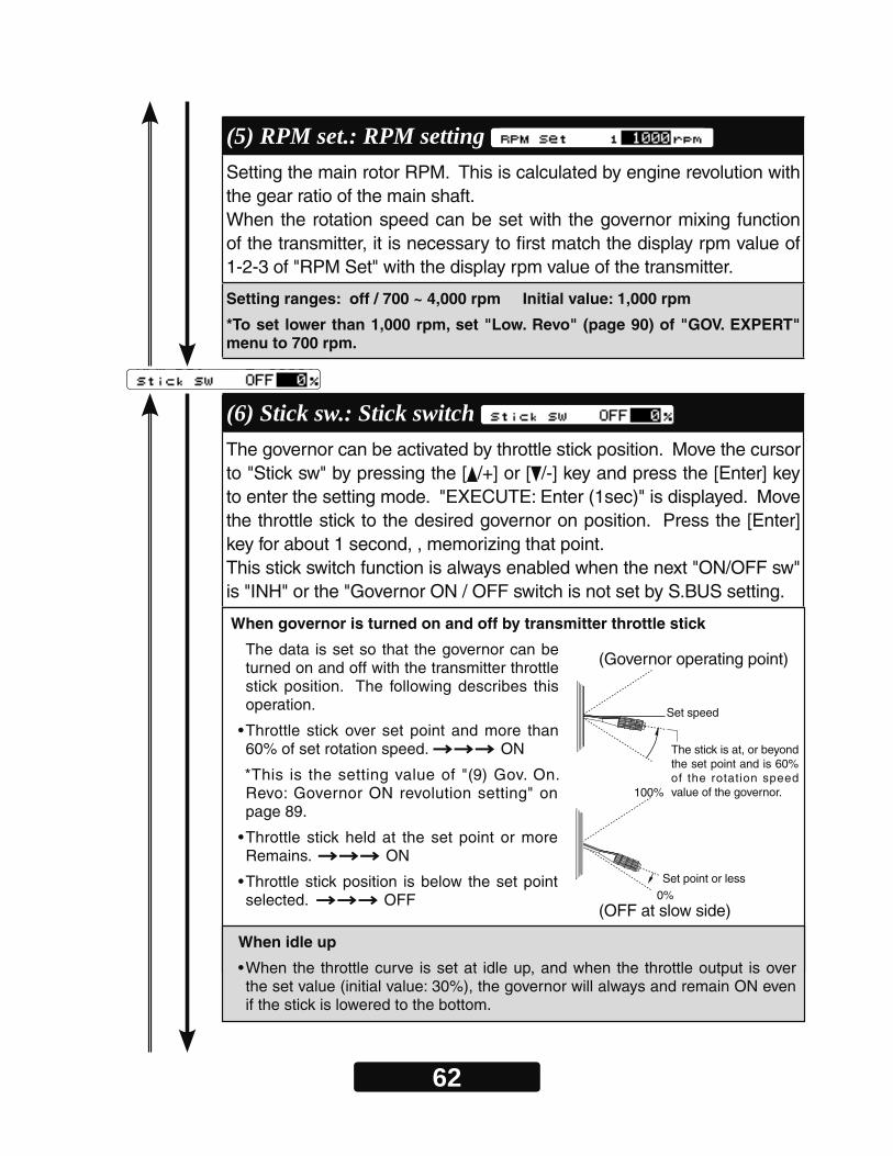
(5) RPM set.: RPM setting Setting the main rotor RPM. This is calculated by engine revolution with the gear ratio of the main shaft.When the rotation speed can be set with the governor mixing function of the transmitter, it is necessary to first match the display rpm value of 1-2-3 of "RPM Set" with the display rpm value of the transmitter.
Setting ranges: off / 700 ~ 4,000 rpm Initial value: 1,000 rpm
*To set lower than 1,000 rpm, set "Low. Revo" (page 90) of "GOV. EXPERT" menu to 700 rpm.
(6) Stick sw.: Stick switch The governor can be activated by throttle stick position. Move the cursor to "Stick sw" by pressing the [ /+] or [ /-] key and press the [Enter] key to enter the setting mode. "EXECUTE: Enter (1sec)" is displayed. Move the throttle stick to the desired governor on position. Press the [Enter] key for about 1 second, , memorizing that point.This stick switch function is always enabled when the next "ON/OFF sw" is "INH" or the "Governor ON / OFF switch is not set by S.BUS setting.
When governor is turned on and off by transmitter throttle stick
The data is set so that the governor can be turned on and off with the transmitter throttle stick position. The following describes this operation.
• Throttle stick over set point and more than 60% of set rotation speed. ON
*This is the setting value of "(9) Gov. On. Revo: Governor ON revolution setting" on page 89.
• Throttle stick held at the set point or more Remains. ON
• Throttle stick position is below the set point selected. OFF
When idle up
• When the throttle curve is set at idle up, and when the throttle output is over the set value (initial value: 30%), the governor will always and remain ON even if the stick is lowered to the bottom.
(OFF at slow side)
Set point or less0%
100%
(Governor operating point)
Set speed
The stick is at, or beyond the set point and is 60% of the rotation speed value of the governor.
63
When you activate the switch, the direction setting of the switch is displayed. Select the switch ON / OFF direction (NORM / REV) with the [ /+] or [ /-] key.
When Battery Fail Safe is enabled, items for setting the throttle servo position are displayed. The setting method is the same as "Stick sw", so please refer tothis section of the manual for information on setting this function.
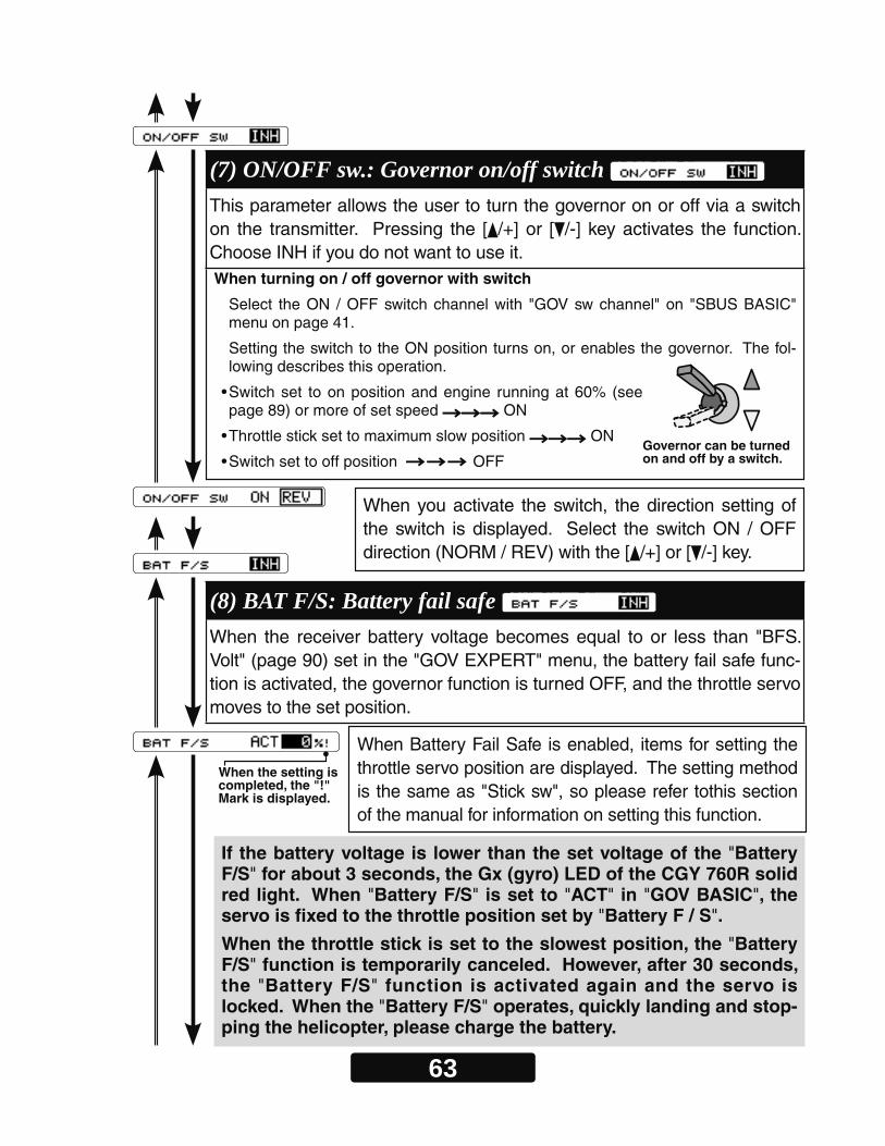
When turning on / off governor with switch
Select the ON / OFF switch channel with "GOV sw channel" on "SBUS BASIC" menu on page 41.
Setting the switch to the ON position turns on, or enables the governor. The fol-lowing describes this operation.
• Switch set to on position and engine running at 60% (see page 89) or more of set speed ON
• Throttle stick set to maximum slow position ON
• Switch set to off position OFF
(7) ON/OFF sw.: Governor on/off switch This parameter allows the user to turn the governor on or off via a switch on the transmitter. Pressing the [ /+] or [ /-] key activates the function. Choose INH if you do not want to use it.
Governor can be turned on and off by a switch.
(8) BAT F/S: Battery fail safe When the receiver battery voltage becomes equal to or less than "BFS. Volt" (page 90) set in the "GOV EXPERT" menu, the battery fail safe func-tion is activated, the governor function is turned OFF, and the throttle servo moves to the set position.
When the setting is completed, the "!" Mark is displayed.
If the battery voltage is lower than the set voltage of the "Battery F/S" for about 3 seconds, the Gx (gyro) LED of the CGY 760R solid red light. When "Battery F/S" is set to "ACT" in "GOV BASIC", the servo is fixed to the throttle position set by "Battery F / S".
When the throttle stick is set to the slowest position, the "Battery F/S" function is temporarily canceled. However, after 30 seconds, the "Battery F/S" function is activated again and the servo is locked. When the "Battery F/S" operates, quickly landing and stop-ping the helicopter, please charge the battery.
64
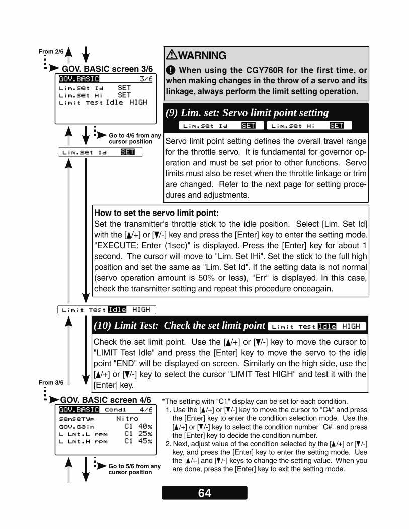
WARNING When using the CGY760R for the first time, or
when making changes in the throw of a servo and its linkage, always perform the limit setting operation.
How to set the servo limit point:Set the transmitter's throttle stick to the idle position. Select [Lim. Set Id] with the [ /+] or [ /-] key and press the [Enter] key to enter the setting mode. "EXECUTE: Enter (1sec)" is displayed. Press the [Enter] key for about 1 second. The cursor will move to "Lim. Set IHi". Set the stick to the full high position and set the same as "Lim. Set Id". If the setting data is not normal (servo operation amount is 50% or less), "Err" is displayed. In this case, check the transmitter setting and repeat this procedure onceagain.
GOV. BASIC screen 4/6
From 3/6
Go to 5/6 from any cursor position
(10) Limit Test: Check the set limit point Check the set limit point. Use the [ /+] or [ /-] key to move the cursor to "LIMIT Test Idle" and press the [Enter] key to move the servo to the idle point "END" will be displayed on screen. Similarly on the high side, use the [ /+] or [ /-] key to select the cursor "LIMIT Test HIGH" and test it with the [Enter] key.
*The setting with "C1" display can be set for each condition.1. Use the [ /+] or [ /-] key to move the cursor to "C#" and press
the [Enter] key to enter the condition selection mode. Use the [ /+] or [ /-] key to select the condition number "C#" and press the [Enter] key to decide the condition number.
2. Next, adjust value of the condition selected by the [ /+] or [ /-] key, and press the [Enter] key to enter the setting mode. Use the [ /+] and [ /-] keys to change the setting value. When you are done, press the [Enter] key to exit the setting mode.
GOV. BASIC screen 3/6
From 2/6
Go to 4/6 from any cursor position
(9) Lim. set: Servo limit point setting Servo limit point setting defines the overall travel range for the throttle servo. It is fundamental for governor op-eration and must be set prior to other functions. Servo limits must also be reset when the throttle linkage or trim are changed. Refer to the next page for setting proce-dures and adjustments.

65
(11) SenseTyp: Sensor type Select the type of governor sensor.Nitro (BPS-1 backplate; Magnet Type)1:1 Magnet "1:1 Mag" (Magnet type applied to helicopter part that turns at the same RPM as the main rotor)HPoleEP: For Electric motors 8 poles and aboveLPoleEP: For electric motors 6 poles.
(12) GOV Gain: Governor gain Governor Gain. If the value of the Governor Gain is set too low, the helicopter's RPM will fluctuate with collective and cyclic pitch changes. Conversely, if the number is too high, the RPM itself will fluctuate and surge during flight.
Setting ranges: 1 ~ 100%
Initial value: Nitro = 40%, 1:1Magn = 60%, HPoleEP= 30%, LPoleEP = 10%
(13) L Lmt. Hov / Idle : Low limit RPM Low RPM Limit sets the minimum amount of throttle that the governor will command during an over-speed situation. Too low of value the en-gine could shut off or not recover power quickly enough during the next collective movement. If the value is set too high, the governor will not control overspeed when the rotor head is unloaded. Use:L Lmt. Hov: For RPMS of 700-1700 L Lmt. Idle: For RPMS of 1701-4000
Setting ranges: L Lmt. Hov =0 ~ 80%, L Lmt. Idle = 10 ~ 80%
Initial value: L Lmt. Hov = 25%, L Lmt. Idle = 45%
Cond
Cond
Cond
66
GOV. BASIC screen 6/6
GOV. BASIC screen 5/6
From 4/6
From 5/6
Go to the menu title of GOV. BASIC screen 1/6
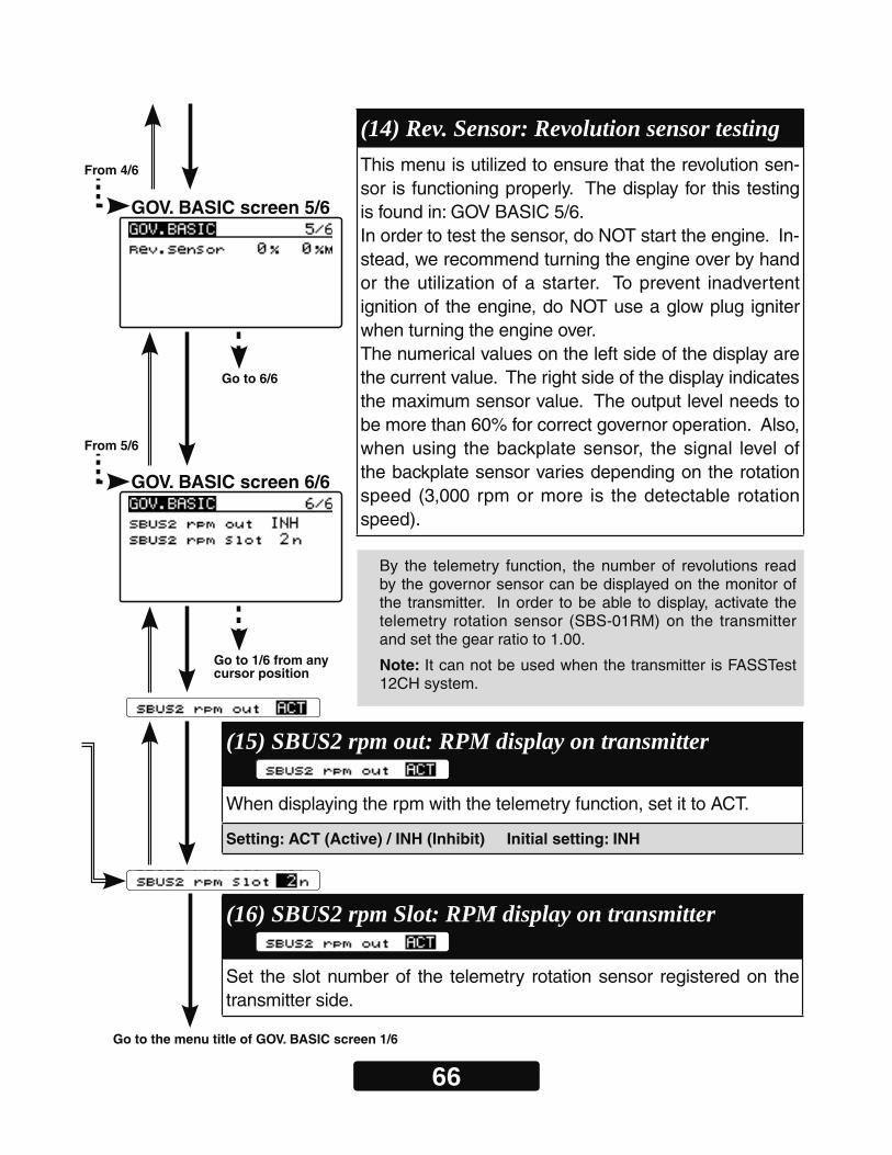
(14) Rev. Sensor: Revolution sensor testing This menu is utilized to ensure that the revolution sen-sor is functioning properly. The display for this testing is found in: GOV BASIC 5/6. In order to test the sensor, do NOT start the engine. In-stead, we recommend turning the engine over by hand or the utilization of a starter. To prevent inadvertent ignition of the engine, do NOT use a glow plug igniter when turning the engine over.The numerical values on the left side of the display are the current value. The right side of the display indicates the maximum sensor value. The output level needs to be more than 60% for correct governor operation. Also, when using the backplate sensor, the signal level of the backplate sensor varies depending on the rotation speed (3,000 rpm or more is the detectable rotation speed).
Go to 1/6 from any cursor position
Go to 6/6
By the telemetry function, the number of revolutions read by the governor sensor can be displayed on the monitor of the transmitter. In order to be able to display, activate the telemetry rotation sensor (SBS-01RM) on the transmitter and set the gear ratio to 1.00.
Note: It can not be used when the transmitter is FASSTest 12CH system.
(15) SBUS2 rpm out: RPM display on transmitter When displaying the rpm with the telemetry function, set it to ACT.
Setting: ACT (Active) / INH (Inhibit) Initial setting: INH
(16) SBUS2 rpm Slot: RPM display on transmitter Set the slot number of the telemetry rotation sensor registered on the transmitter side.

67
Governor Speed Setting
(8) "RPM channel" " " to the governor -
" "the "Governor Basic Setting"
Direct set by transmitter on Gov. mixing• When governor mixing is used to switch the RPM of the rotor head speed, the head speed can be switched with each condition of the switch.
*For a description of the governor mixing, please refer to your transmitter’s manual.
Using by 3 position switch• Set the RPM at each switch position in the "(5) RPM setting" menu within the "Gover-nor Basic Setting" section earlier in this manual (page 62).
Governor operation-
Condition of the governor to be onFor safety purposes, the governor is turned on when the conditions below are satisfied.
•The on/off switch conditions are set to off during power on.
•The stick switch is in the on position when it is used.
•The on/off switch is in the on position when it is used.
•Setting speed is not off.
•The engine speed exceeds to 60 % of the setting speed.
•The speed sensor is working properly.
WARNING Safety reminder: Remember to configure your transmitter fail safe settings for
not only the throttle channel but also the governor ON/OFF channel to ensure that the governor correctly disengages should the radio enter a fail safe condition.
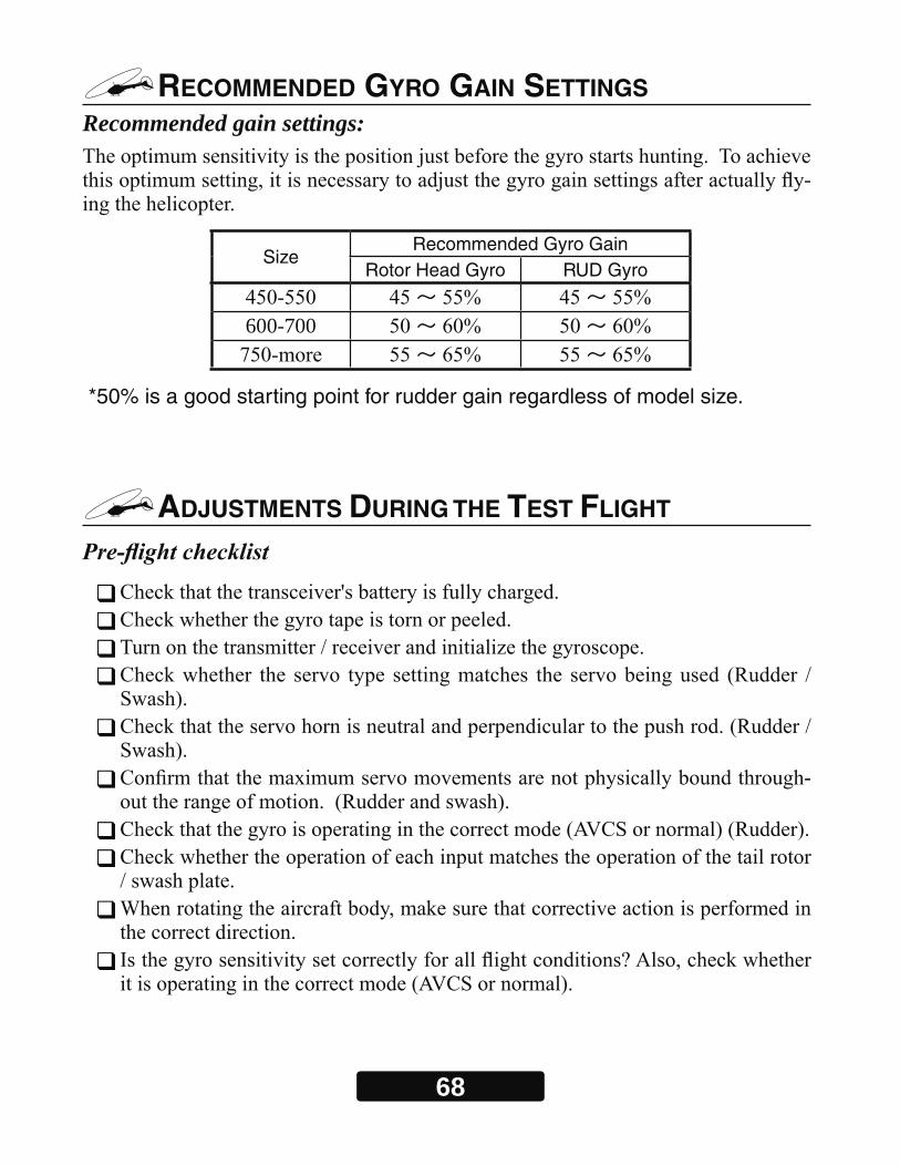
68
RECOMMENDED GYRO GAIN SETTINGS Recommended gain settings:
-
SizeRecommended Gyro Gain
Rotor Head Gyro RUD Gyro
~ ~
600-700 ~ ~
~ ~
*50% is a good starting point for rudder gain regardless of model size.
ADJUSTMENTS DURING THE TEST FLIGHT
-

69
WARNING
Always level the swash plate using the cyclic stick before applying throttle and spooling up the main rotor blades. During takeoff small corrections may be necessary. If you make large corrections while the helicopter is on the ground, it may tip over since the helicopter is firmly on the ground and the gyros are over-compensating due to the lack of movement.
Some helicopters may have a tendency to resonate/shake during spool up. Always leave the helicopter on the ground until this resonance or shaking goes away. If this issue continues, it is recommended to try some rubber skid stops or take off from a softer surface such as grass. Vibrations contribute to this ground resonance. Verify that everything on your model is balanced correctly.
*When the CGY760R is used with an ESC or BEC and a power switch is not used, there is a possibility of an intermittent connection when connecting the flight battery. This may cause the CGY760R initialization to fail. Always ensure that the gyro has initialized properly by verifying that the gyros are compensating as the helicopter is moved. It is recommended to use a power switch on the power supply line to avoid this possibility.
Rudder Gyro Trim Flight:
-
called tail " "
can vary drastically from model to model, and the exact value should not play a part
70
TIPS FOR USING THE GOVERNOR WITH ELECTRIC MODELS
WARNING
Safety Reminder: Remove both main and tail blades from the model and/or disengage the motor’s pinion from the main gear before proceeding with any electric governor set up.
-
You may use either a brushless phase sensor or the traditional governor magnetic
" "
" " or " "
" "" " The greater the electronic speed control headroom built into the model as a func-
-
-
71
TRANSMITTER Rotor head Gyro GAIN SET-UP
WARNING
Verify that the gyro compensates in the correct direction for all three axes before flight. If the compensation direction is incorrect, the model will roll, flip, or pirouette uncontrollably even before it leaves the ground.
Transmitter Set-up for adjusting cyclic gains via the transmitter.
Using the Remote Gain Functions (roll, pitch and yaw)1. Some Futaba transmitters contain auxiliary gain functions for aileron, elevator and
yaw. Please refer to your transmitter’s instruction manual. Assign the Gyro (RUD), Gyro (Rotor Head replaces AIL/ELE) channels within the transmitter. Within the CGY760R "S.BUS BASIC" menu Rotor Head Gyro Gain – In the SBUS menu as-signing "Rotor Head gain" to a channel will allow the Rotor head gain to be adjusted via the transmitter. If you are using a 5 or 6CH transmitter, setting "Rotor Head gain" to "INH" will then default the gain to "BaseGain" in the "FLT. TUNE" menu. Suggested setting and default is CH9. Tail Rotor Gain "Gain RUD" – In the SBUS menu assigning "Gain RUD" to a free transmitter channel will allow for the tail rotor gain to be adjusted via the transmitter. Suggested setting and default is CH5.
2. The gyro function within your transmitter should list all three gain channels. Adjust-ments can be made from within this function. The gyro function can usually be as-signed to various switches or conditions to offer greater adjustability. Please refer to your transmitter’s instruction manual for further details.
Setting the CGY760R gains by using endpoints or manual adjustments1. If your transmitter does not support the remote gain adjustment it is still possible to use
a spare channel on the transmitter to make the adjustments. Assign unused channels (verify that these channels are not assigned or operated by a switch or dial) within the transmitter. Set the "Rotor Head gain" channels in the "S.BUS.Basic" menu to the appro-priate channel. Use the end point adjustment within your transmitter for these channels to make the gain adjustments and the reverse function within the transmitter to set the mode "AVCS/NOR". Conditions with the transmitter may also be used to achieve different gains based upon flight modes. Please refer to your transmitter’s instruction manual for further details.
Manual gain adjustment1. If your setup does not leave any channels free, or if your transmitter does not support
auxiliary gain adjustment, then it is possible to adjust the gain manually within the CGY760R. Set both the "Rotor Head gain" in the "SBUS. BASIC" menu to "INH". The gain adjustments are now made by entering the "BaseGain" in the "FLT. TUNE" menu and pressing the [ /+] or [ /-] key.
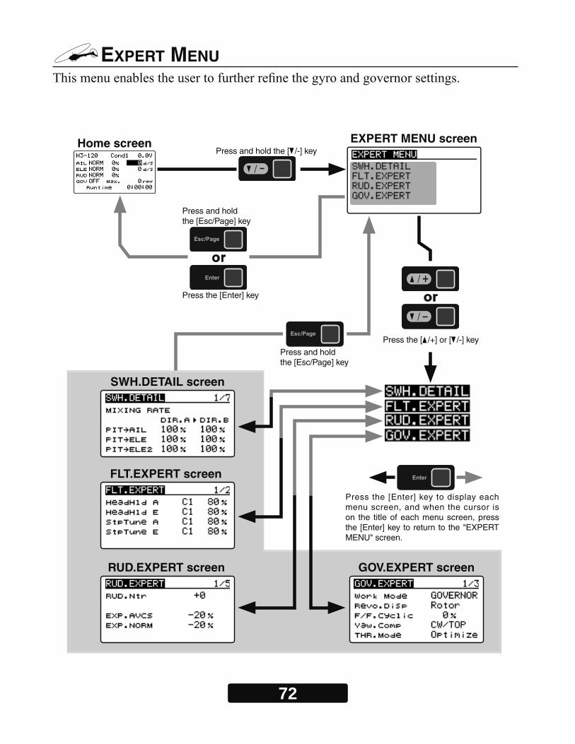
72
EXPERT MENU
Home screen EXPERT MENU screen
SWH.DETAIL screen
FLT.EXPERT screen
RUD.EXPERT screen GOV.EXPERT screen
Press the [ /+] or [ /-] key
Press the [Enter] key
Press the [Enter] key to display each menu screen, and when the cursor is on the title of each menu screen, press the [Enter] key to return to the "EXPERT MENU" screen.
Press and holdthe [Esc/Page] key
Press and holdthe [Esc/Page] key
Press and hold the [ /-] key
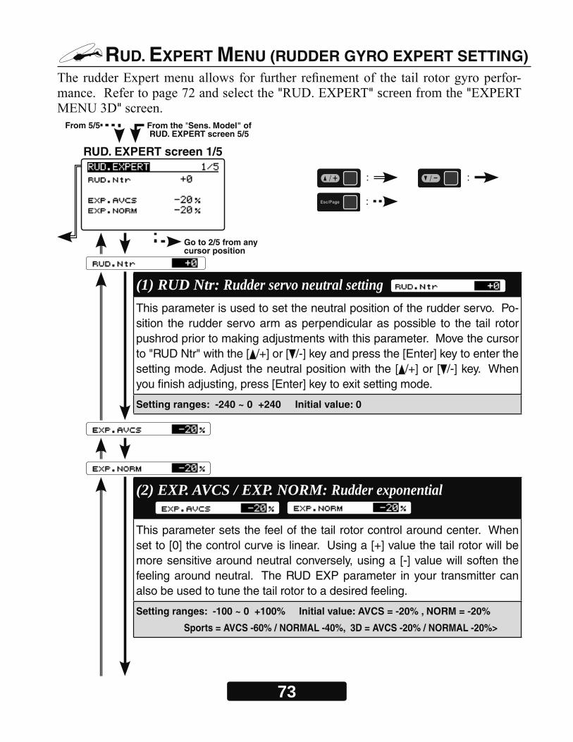
73
RUD. EXPERT MENU (RUDDER GYRO EXPERT SETTING)-
" " screen from the ""
(1) RUD Ntr: Rudder servo neutral setting This parameter is used to set the neutral position of the rudder servo. Po-sition the rudder servo arm as perpendicular as possible to the tail rotor pushrod prior to making adjustments with this parameter. Move the cursor to "RUD Ntr" with the [ /+] or [ /-] key and press the [Enter] key to enter the setting mode. Adjust the neutral position with the [ /+] or [ /-] key. When you finish adjusting, press [Enter] key to exit setting mode.
Setting ranges: -240 ~ 0 +240 Initial value: 0
(2) EXP. AVCS / EXP. NORM: Rudder exponential This parameter sets the feel of the tail rotor control around center. When set to [0] the control curve is linear. Using a [+] value the tail rotor will be more sensitive around neutral conversely, using a [-] value will soften the feeling around neutral. The RUD EXP parameter in your transmitter can also be used to tune the tail rotor to a desired feeling.
Setting ranges: -100 ~ 0 +100% Initial value: AVCS = -20% , NORM = -20%
Sports = AVCS -60% / NORMAL -40%, 3D = AVCS -20% / NORMAL -20%>
From 5/5 From the "Sens. Model" of RUD. EXPERT screen 5/5
Go to 2/5 from any cursor position
RUD. EXPERT screen 1/5
: :
:

74
(3) CNT. DlIn: Control delay in This parameter sets the delay as you move the stick from neutral toward left or right. Larger values result in a softer tail rotor feel off center. This parameter must be adjusted individually for LEFT and RIGHT tail rotor commands. Hold the cursor to "CNT. DlIn" by pressing the [ /+] or [ /-] key. Move the rudder stick to the left or right by amount the " "cursor moves. Enter the setting mode by pressing the [Enter] key, adjust the amount of delay with the [ /+] or [ /-] key, and then press the [Enter] key to exit the setting mode. Follow these same procedures to adjust the tail rotor feel in the opposite direction.
Setting ranges: 0 ~ 20 n Initial value: 15 n
(4) CNT. DlOut: Control delay out This parameter sets the delay when the stick is returned back to the neu-tral position. This parameter is useful to tune how aggressively the tail rotor stops following a pirouette. The higher the value, the softer the stop. This parameter must be adjusted individually for LEFT and RIGHT tail ro-tor commands. The setting method is the same as "CNT. DlIn", so please refer to the information above.
Setting ranges: 0 ~ 20 n Initial value: 12 n
RUD. EXPERT screen 2/5
From 1/5
Go to 3/5 from any cursor position

75
(5) ANG: Pirouette speed
This parameter adjusts the maximum pirouette speed of the tail rotor that the gyro will allow at 100% dual rate. Use the [ /+] or [ /-] key to adjust the maximum commanded pirouette rate.
Setting ranges: 100 ~ 999 d Initial value: = 720 d,
(6) F/F.Rate U / F/F.Rate D: F/F mixing rate Feed Forward mix is used to counteract sudden increases in torque from the motor during fast collective pitch changes. If you notice a tail kick, using (right rudder on Clockwise rotor disk, left rudder on CCW) F/F mixing can be tuned to reduce the tail kick. The mixing amount can be individually set for high pitch side (U) and low pitch (D) side with zero pitch as the center.
Setting ranges: -100 ~ 0 ~ +100% Initial value: +0%
RUD. EXPERT screen 3/5
RUD. EXPERT screen 4/5
Go to 4/5 from any cursor position
Go to 5/5 from any cursor position
From 2/5
From 3/5
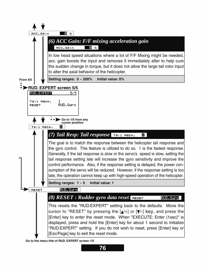
76
(6) ACC Gain: F/F mixing acceleration gain In low head speed situations where a lot of F/F Mixing might be needed, acc. gain boosts the input and removes it immediately after to help cure the sudden change in torque, but it does not allow the large tail rotor input to alter the axial behavior of the helicopter.
Setting ranges: 0 ~ 200% Initial value: 0%
(7) Tail Resp: Tail response The goal is to match the response between the helicopter tail response and the gyro control. This feature is utilized to do so. 1 is the fastest response. Generally, if the tail response is slow or the servo's speed is slow, setting the tail response setting late will increase the gyro sensitivity and improve the control performance. Also, if the response setting is delayed, the power con-sumption of the servo will be reduced. However, if the response setting is too late, the operation cannot keep up with high-speed operation of the helicopter.
Setting ranges: 1 ~ 5 Initial value: 1
RUD. EXPERT screen 5/5
Go to 1/5 from any cursor position
From 4/5
Go to the menu title of RUD. EXPERT screen 1/5
(8) RESET : Rudder gyro data reset This resets the "RUD.EXPERT" setting back to the defaults. Move the cursor to "RESET" by pressing the [ /+] or [ /-] key, and press the [Enter] key to enter the reset mode. When "EXECUTE: Enter (1sec)" is displayed, press and hold the [Enter] key for about 1 second to initialize "RUD.EXPERT" setting. If you do not wish to reset, press [Enter] key or [Esc/Page] key to exit the reset mode.
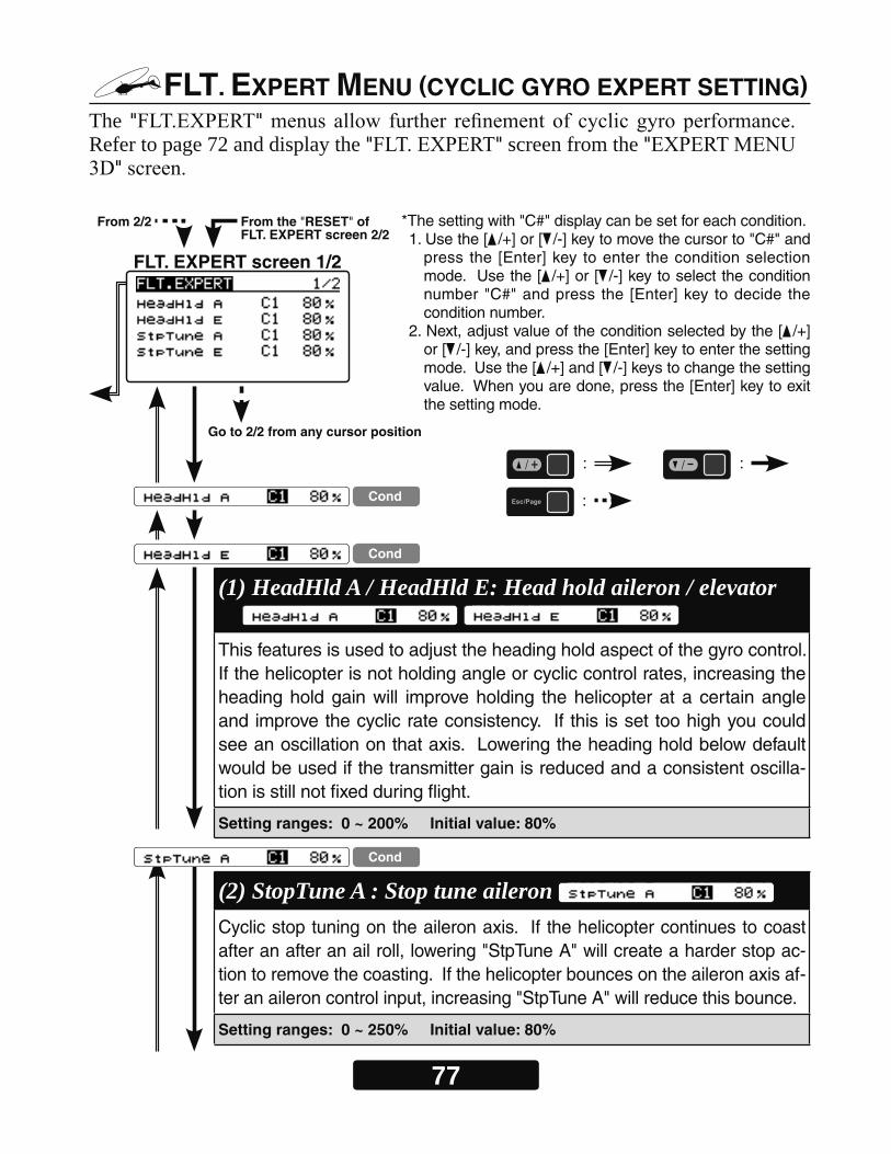
77
FLT. EXPERT MENU (CYCLIC GYRO EXPERT SETTING)The " "Refer to page 72 and display the " " screen from the "
"
FLT. EXPERT screen 1/2
From 2/2 From the "RESET" of FLT. EXPERT screen 2/2
Go to 2/2 from any cursor position
*The setting with "C#" display can be set for each condition.1. Use the [ /+] or [ /-] key to move the cursor to "C#" and
press the [Enter] key to enter the condition selection mode. Use the [ /+] or [ /-] key to select the condition number "C#" and press the [Enter] key to decide the condition number.
2. Next, adjust value of the condition selected by the [ /+] or [ /-] key, and press the [Enter] key to enter the setting mode. Use the [ /+] and [ /-] keys to change the setting value. When you are done, press the [Enter] key to exit the setting mode.
: :
: Cond
Cond
Cond
(1) HeadHld A / HeadHld E: Head hold aileron / elevator This features is used to adjust the heading hold aspect of the gyro control. If the helicopter is not holding angle or cyclic control rates, increasing the heading hold gain will improve holding the helicopter at a certain angle and improve the cyclic rate consistency. If this is set too high you could see an oscillation on that axis. Lowering the heading hold below default would be used if the transmitter gain is reduced and a consistent oscilla-tion is still not fixed during flight.
Setting ranges: 0 ~ 200% Initial value: 80%
(2) StopTune A : Stop tune aileron Cyclic stop tuning on the aileron axis. If the helicopter continues to coast after an after an ail roll, lowering "StpTune A" will create a harder stop ac-tion to remove the coasting. If the helicopter bounces on the aileron axis af-ter an aileron control input, increasing "StpTune A" will reduce this bounce.
Setting ranges: 0 ~ 250% Initial value: 80%
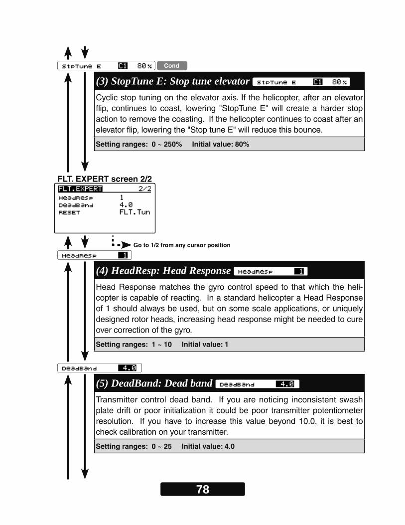
78
Cond
(3) StopTune E: Stop tune elevator Cyclic stop tuning on the elevator axis. If the helicopter, after an elevator flip, continues to coast, lowering "StopTune E" will create a harder stop action to remove the coasting. If the helicopter continues to coast after an elevator flip, lowering the "Stop tune E" will reduce this bounce.
Setting ranges: 0 ~ 250% Initial value: 80%
(4) HeadResp: Head Response Head Response matches the gyro control speed to that which the heli-copter is capable of reacting. In a standard helicopter a Head Response of 1 should always be used, but on some scale applications, or uniquely designed rotor heads, increasing head response might be needed to cure over correction of the gyro.
Setting ranges: 1 ~ 10 Initial value: 1
(5) DeadBand: Dead band Transmitter control dead band. If you are noticing inconsistent swash plate drift or poor initialization it could be poor transmitter potentiometer resolution. If you have to increase this value beyond 10.0, it is best to check calibration on your transmitter.
Setting ranges: 0 ~ 25 Initial value: 4.0
Go to 1/2 from any cursor position
FLT. EXPERT screen 2/2
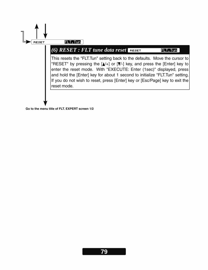
79
(6) RESET : FLT tune data reset This resets the "FLT.Tun" setting back to the defaults. Move the cursor to "RESET" by pressing the [ /+] or [ /-] key, and press the [Enter] key to enter the reset mode. With "EXECUTE: Enter (1sec)" displayed, press and hold the [Enter] key for about 1 second to initialize "FLT.Tun" setting. If you do not wish to reset, press [Enter] key or [Esc/Page] key to exit the reset mode.
Go to the menu title of FLT. EXPERT screen 1/2
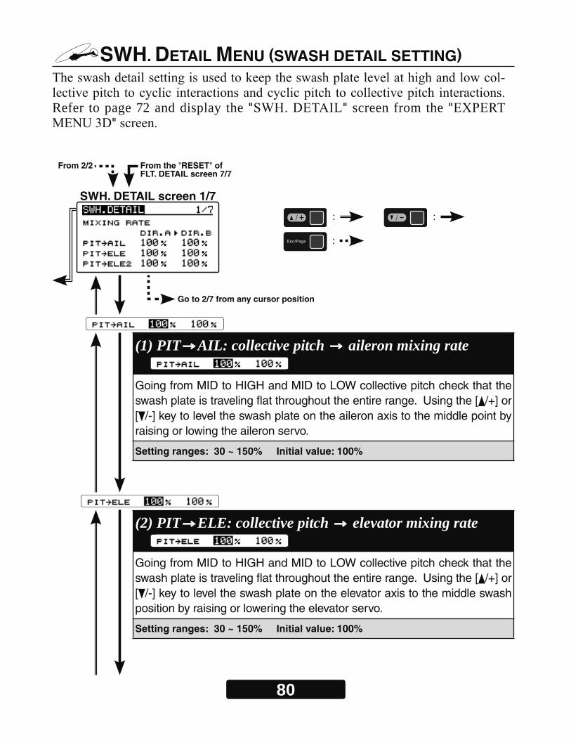
80
SWH. DETAIL MENU (SWASH DETAIL SETTING)-
Refer to page 72 and display the " " screen from the ""
SWH. DETAIL screen 1/7
From 2/2 From the "RESET" of FLT. DETAIL screen 7/7
Go to 2/7 from any cursor position
: :
:
(1) PIT AIL: collective pitch aileron mixing rate Going from MID to HIGH and MID to LOW collective pitch check that the swash plate is traveling flat throughout the entire range. Using the [ /+] or [ /-] key to level the swash plate on the aileron axis to the middle point by raising or lowing the aileron servo.
Setting ranges: 30 ~ 150% Initial value: 100%
(2) PIT ELE: collective pitch elevator mixing rate Going from MID to HIGH and MID to LOW collective pitch check that the swash plate is traveling flat throughout the entire range. Using the [ /+] or [ /-] key to level the swash plate on the elevator axis to the middle swash position by raising or lowering the elevator servo.
Setting ranges: 30 ~ 150% Initial value: 100%
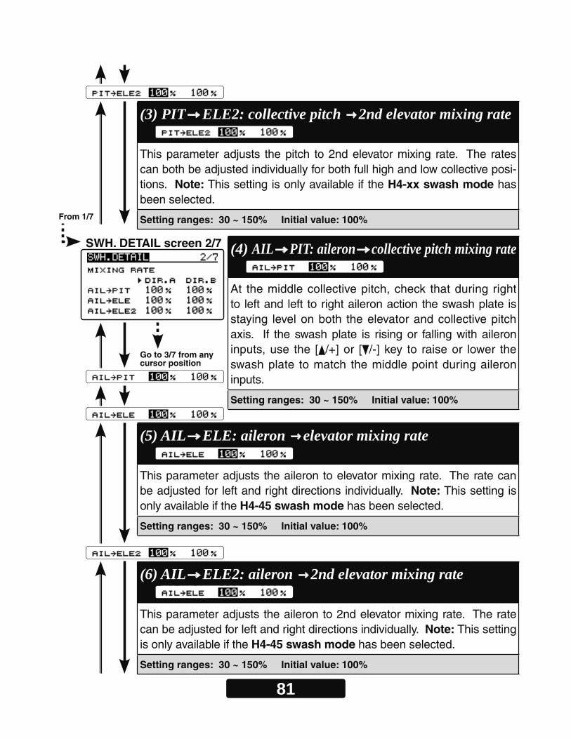
81
Go to 3/7 from any cursor position
(4) AIL PIT: aileron collective pitch mixing rate At the middle collective pitch, check that during right to left and left to right aileron action the swash plate is staying level on both the elevator and collective pitch axis. If the swash plate is rising or falling with aileron inputs, use the [ /+] or [ /-] key to raise or lower the swash plate to match the middle point during aileron inputs.
Setting ranges: 30 ~ 150% Initial value: 100%
(3) PIT ELE2: collective pitch 2nd elevator mixing rate This parameter adjusts the pitch to 2nd elevator mixing rate. The rates can both be adjusted individually for both full high and low collective posi-tions. Note: This setting is only available if the H4-xx swash mode has been selected.
Setting ranges: 30 ~ 150% Initial value: 100%
(5) AIL ELE: aileron elevator mixing rate This parameter adjusts the aileron to elevator mixing rate. The rate can be adjusted for left and right directions individually. Note: This setting is only available if the H4-45 swash mode has been selected.
Setting ranges: 30 ~ 150% Initial value: 100%
(6) AIL ELE2: aileron 2nd elevator mixing rate This parameter adjusts the aileron to 2nd elevator mixing rate. The rate can be adjusted for left and right directions individually. Note: This setting is only available if the H4-45 swash mode has been selected.
Setting ranges: 30 ~ 150% Initial value: 100%
SWH. DETAIL screen 2/7
From 1/7
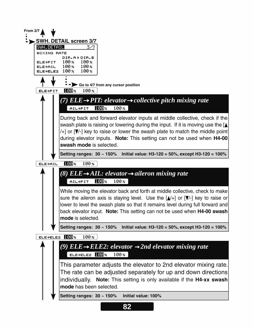
82
SWH. DETAIL screen 3/7
From 2/7
Go to 4/7 from any cursor position
(7) ELE PIT: elevator collective pitch mixing rate During back and forward elevator inputs at middle collective, check if the swash plate is raising or lowering during the input. If it is moving use the [/+] or [ /-] key to raise or lower the swash plate to match the middle point during elevator inputs. Note: This setting can not be used when H4-00 swash mode is selected.
Setting ranges: 30 ~ 150% Initial value: H3-120 = 50%, except H3-120 = 100%
(8) ELE AIL: elevator aileron mixing rate While moving the elevator back and forth at middle collective, check to make sure the aileron axis is staying level. Use the [ /+] or [ /-] key to raise or lower to level the swash plate so that it remains level during full forward and back elevator input. Note: This setting can not be used when H4-00 swash mode is selected.
Setting ranges: 30 ~ 150% Initial value: H3-120 = 50%, except H3-120 = 100%
(9) ELE ELE2: elevator 2nd elevator mixing rate This parameter adjusts the elevator to 2nd elevator mixing rate. The rate can be adjusted separately for up and down directions individually. Note: This setting is only available if the H4-xx swash mode has been selected.
Setting ranges: 30 ~ 150% Initial value: 100%

83
SWH. DETAIL screen 4/7
From 3/7
Go to 5/7 from any cursor position
(10) AIL High / AIL Low: Linkage compensation aileron At HIGH pitch and LOW pitch check to make sure that the swash plate is staying level on the elevator and collective axis when using aileron inputs. If the swash plate is rising or falling, use the [ /+] or [ /-] key to maintain the swash plate position the same as that noted in the centered aileron inputs. Note: check all four directions: high/right; high/left; low/right; low/left
Setting ranges: 0 ~ 100% Initial value: 0%
(11) AIL Dir: Compensation direction of the aileron If the above Data (+/-) correction from 0-100 is NOT in the correct com-pensation direction, change the value from [+] or [-] using the [ /+] or [ /-] key.
Setting: +/- Initial setting: +
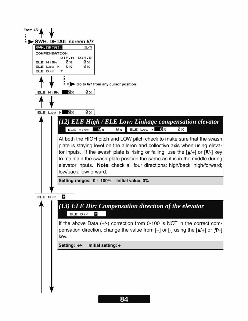
84
SWH. DETAIL screen 5/7
From 4/7
Go to 6/7 from any cursor position
(12) ELE High / ELE Low: Linkage compensation elevator At both the HIGH pitch and LOW pitch check to make sure that the swash plate is staying level on the aileron and collective axis when using eleva-tor inputs. If the swash plate is rising or falling, use the [ /+] or [ /-] key to maintain the swash plate position the same as it is in the middle during elevator inputs. Note: check all four directions: high/back; high/forward; low/back; low/forward.
Setting ranges: 0 ~ 100% Initial value: 0%
(13) ELE Dir: Compensation direction of the elevator If the above Data (+/-) correction from 0-100 is NOT in the correct com-pensation direction, change the value from [+] or [-] using the [ /+] or [ /-] key.
Setting: +/- Initial setting: +
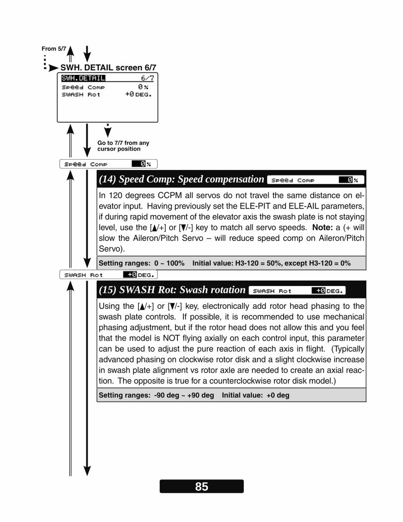
85
From 5/7
Go to 7/7 from any cursor position
(14) Speed Comp: Speed compensation In 120 degrees CCPM all servos do not travel the same distance on el-evator input. Having previously set the ELE-PIT and ELE-AIL parameters, if during rapid movement of the elevator axis the swash plate is not staying level, use the [ /+] or [ /-] key to match all servo speeds. Note: a (+ will slow the Aileron/Pitch Servo – will reduce speed comp on Aileron/Pitch Servo).
Setting ranges: 0 ~ 100% Initial value: H3-120 = 50%, except H3-120 = 0%
(15) SWASH Rot: Swash rotation Using the [ /+] or [ /-] key, electronically add rotor head phasing to the swash plate controls. If possible, it is recommended to use mechanical phasing adjustment, but if the rotor head does not allow this and you feel that the model is NOT flying axially on each control input, this parameter can be used to adjust the pure reaction of each axis in flight. (Typically advanced phasing on clockwise rotor disk and a slight clockwise increase in swash plate alignment vs rotor axle are needed to create an axial reac-tion. The opposite is true for a counterclockwise rotor disk model.)
Setting ranges: -90 deg ~ +90 deg Initial value: +0 deg
SWH. DETAIL screen 6/7

86
SWH. DETAIL screen 7/7
From 6/7
Go to 1/7 from any cursor position
(16) RESET : Swash detail data reset This resets the "SWH.DETAIL" setting back to the defaults. Move the cur-sor to "RESET" by pressing the [ /+] or [ /-] key. Press the [Enter] key to enter the reset mode. When "EXECUTE: Enter (1sec)" is displayed, press and hold the [Enter] key for about 1 second to initialize "SWH.DETAIL" setting. If you do not wish to reset, press either the [Enter] key or [Esc/Page] key to exit reset mode.
Go to the menu title of SWH. DETAIL screen 1/7
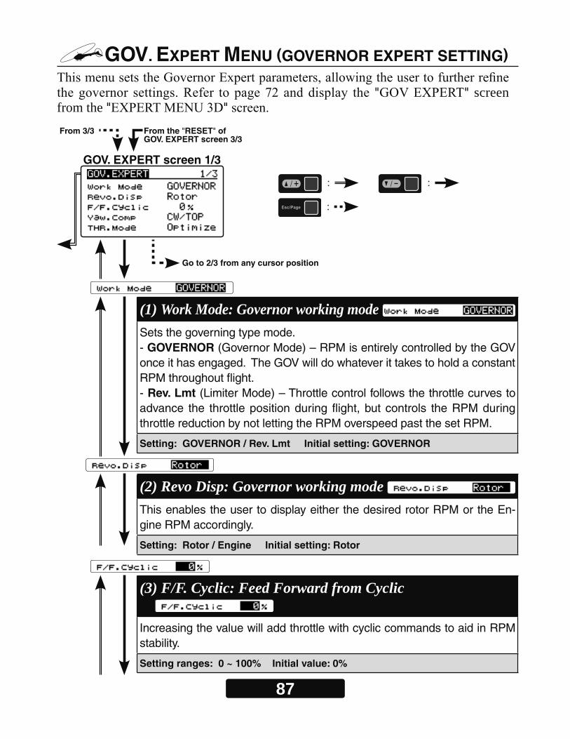
87
Go to 2/3 from any cursor position
GOV. EXPERT MENU (GOVERNOR EXPERT SETTING)
" " screen from the " "
GOV. EXPERT screen 1/3
From 3/3 From the "RESET" of GOV. EXPERT screen 3/3
: :
:
(1) Work Mode: Governor working mode Sets the governing type mode.- GOVERNOR (Governor Mode) – RPM is entirely controlled by the GOV once it has engaged. The GOV will do whatever it takes to hold a constant RPM throughout flight. - Rev. Lmt (Limiter Mode) – Throttle control follows the throttle curves to advance the throttle position during flight, but controls the RPM during throttle reduction by not letting the RPM overspeed past the set RPM.
Setting: GOVERNOR / Rev. Lmt Initial setting: GOVERNOR
(2) Revo Disp: Governor working mode This enables the user to display either the desired rotor RPM or the En-gine RPM accordingly.
Setting: Rotor / Engine Initial setting: Rotor
(3) F/F. Cyclic: Feed Forward from Cyclic Increasing the value will add throttle with cyclic commands to aid in RPM stability.
Setting ranges: 0 ~ 100% Initial value: 0%
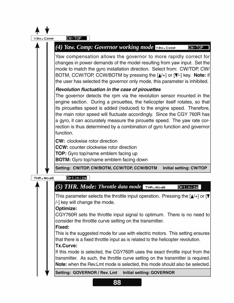
88
(5) THR. Mode: Throttle data mode This parameter selects the throttle input operation. Pressing the [ /+] or [/-] key will change the mode.Optimize:CGY760R sets the throttle input signal to optimum. There is no need to consider the throttle curve setting on the transmitter.Fixed:This is the suggested mode for use with electric motors. This setting ensures that there is a fixed throttle input as is related to the helicopter revolution. Tx.Curve:If this mode is selected, the CGY760R uses the exact throttle input from the transmitter. As such, the throttle curve setting on the transmitter is required. Note: when the Rev.Lmt mode is selected, this mode should also be selected.
Setting: GOVERNOR / Rev. Lmt Initial setting: GOVERNOR
(4) Yaw. Comp: Governor working mode Yaw compensation allows the governor to more rapidly correct for changes in power demands of the model resulting from yaw input. Set the mode to match the gyro installation direction. Select from: CW/TOP, CW/BOTM, CCW/TOP, CCW/BOTM by pressing the [ /+] or [ /-] key. Note: if the user has selected the governor only mode, this parameter is inhibited.
Revolution fluctuation in the case of pirouettesThe governor detects the rpm via the revolution sensor mounted in the engine section. During a pirouettes, the helicopter itself rotates, so that its pirouettes speed is added (reduced) to the engine speed. Therefore, the main rotor speed will fluctuate accordingly. Since the CGY 760R has a gyro, it can accurately measure the pirouette speed. The yaw rate cor-rection is thus determined by a combination of gyro function and governor function.
CW: clockwise rotor directionCCW: counter clockwise rotor directionTOP: Gyro top/name emblem facing upBOTM: Gyro top/name emblem facing down
Setting: CW/TOP, CW/BOTM, CCW/TOP, CCW/BOTM Initial setting: CW/TOP
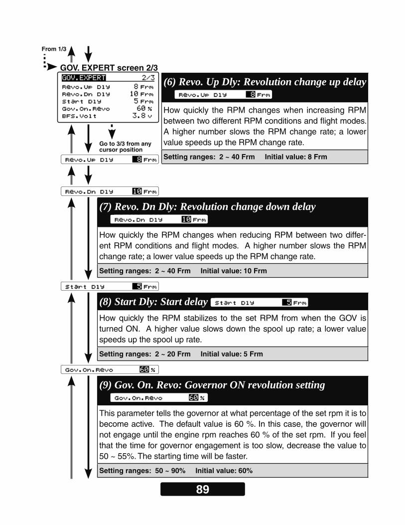
89
Go to 3/3 from any cursor position
(6) Revo. Up Dly: Revolution change up delay How quickly the RPM changes when increasing RPM between two different RPM conditions and flight modes. A higher number slows the RPM change rate; a lower value speeds up the RPM change rate.
Setting ranges: 2 ~ 40 Frm Initial value: 8 Frm
(7) Revo. Dn Dly: Revolution change down delay How quickly the RPM changes when reducing RPM between two differ-ent RPM conditions and flight modes. A higher number slows the RPM change rate; a lower value speeds up the RPM change rate.
Setting ranges: 2 ~ 40 Frm Initial value: 10 Frm
(8) Start Dly: Start delay How quickly the RPM stabilizes to the set RPM from when the GOV is turned ON. A higher value slows down the spool up rate; a lower value speeds up the spool up rate.
Setting ranges: 2 ~ 20 Frm Initial value: 5 Frm
(9) Gov. On. Revo: Governor ON revolution setting This parameter tells the governor at what percentage of the set rpm it is to become active. The default value is 60 %. In this case, the governor will not engage until the engine rpm reaches 60 % of the set rpm. If you feel that the time for governor engagement is too slow, decrease the value to 50 ~ 55%. The starting time will be faster.
Setting ranges: 50 ~ 90% Initial value: 60%
GOV. EXPERT screen 2/3
From 1/3
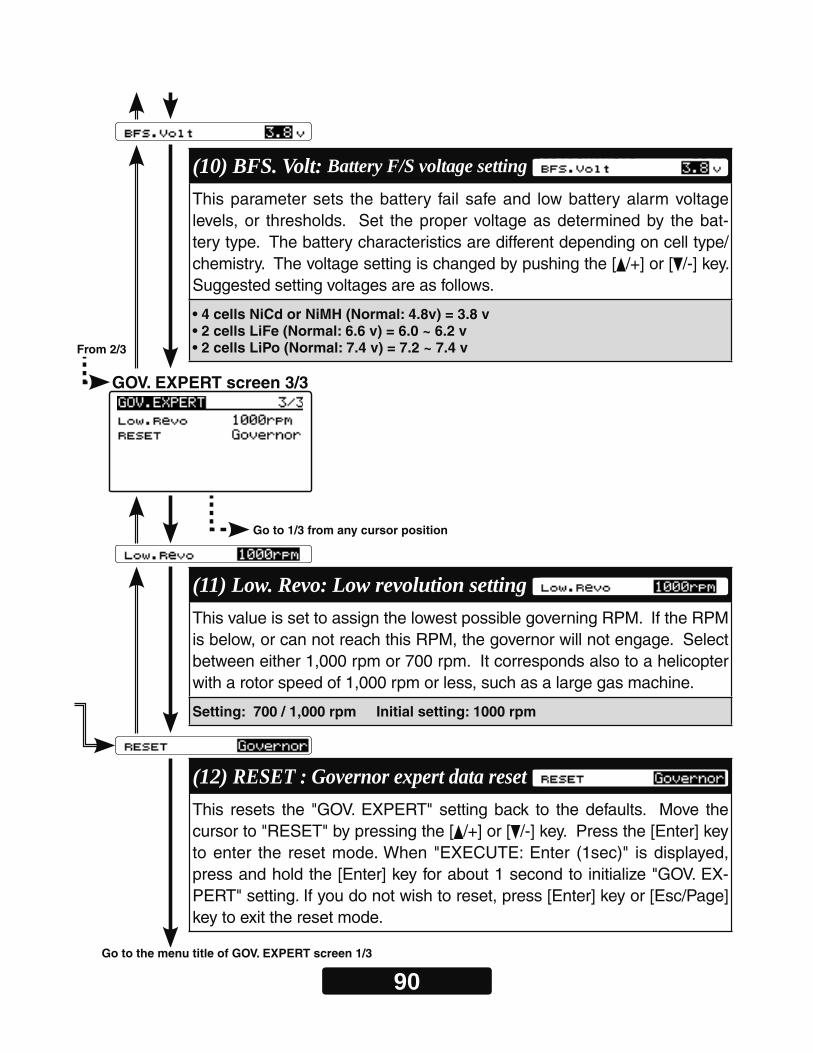
90
GOV. EXPERT screen 3/3
From 2/3
Go to 1/3 from any cursor position
(10) BFS. Volt: Battery F/S voltage setting This parameter sets the battery fail safe and low battery alarm voltage levels, or thresholds. Set the proper voltage as determined by the bat-tery type. The battery characteristics are different depending on cell type/chemistry. The voltage setting is changed by pushing the [ /+] or [ /-] key. Suggested setting voltages are as follows.
• 4 cells NiCd or NiMH (Normal: 4.8v) = 3.8 v• 2 cells LiFe (Normal: 6.6 v) = 6.0 ~ 6.2 v• 2 cells LiPo (Normal: 7.4 v) = 7.2 ~ 7.4 v
(11) Low. Revo: Low revolution setting This value is set to assign the lowest possible governing RPM. If the RPM is below, or can not reach this RPM, the governor will not engage. Select between either 1,000 rpm or 700 rpm. It corresponds also to a helicopter with a rotor speed of 1,000 rpm or less, such as a large gas machine.
Setting: 700 / 1,000 rpm Initial setting: 1000 rpm
(12) RESET : Governor expert data reset This resets the "GOV. EXPERT" setting back to the defaults. Move the cursor to "RESET" by pressing the [ /+] or [ /-] key. Press the [Enter] key to enter the reset mode. When "EXECUTE: Enter (1sec)" is displayed, press and hold the [Enter] key for about 1 second to initialize "GOV. EX-PERT" setting. If you do not wish to reset, press [Enter] key or [Esc/Page] key to exit the reset mode.
Go to the menu title of GOV. EXPERT screen 1/3

91
-FLT. TUNE
CYC. Rt: Cyclic rate setting (page 52)Cnt. AuthAIL: Control Authority Aileron (page 53)Cnt. AuthELE: Control Authority Elevator (page 53)
EXPO.: Exponential (page54)FLT. Styl: Flight style (page54)
-SWH. BASIC
SWS. Rate: Rate adjustment (page 48)PIT. Rate: Rate adjustment (page 49) SWS. Ring (page 49)
- GOV. BASIC
GOV Gain: Governor gain (page 65) L Lmt. Hov : Low limit hovering RPM (page 65) L Lmt. Idle : Low limit idling RPM (page 65)
-FLT. EXPERT
HeadHld A : Head hold aileron (page 77)StopTune A : Stop tune aileron (page 77)HeadResp: Head Response (page 78)
HeadHld E: Head hold elevator (page 77)StopTune E : Stop tune elevator (page 77)
-RUD. EXPERT
EXP. AVCS: Rudder exponential AVCS (page 73)EXP. NORM: Rudder exponential NORMAL (page 73)
CNT. DlIn: Control delay in (page 74)CNT. DlOut: Control delay out (page 74)
ANG: Pirouette speed (page 75)Tail Resp: Tail response (page 76)
3D VIA TRAINER Screen FUNCTIN LIST

92
19.3 mm4-M3
7.0 mm
21.6 mm
WARNING
If using screws to mount the CGY760R to the helicopter, it is impera-tive to ensure that the machine does not vibrate excessively. *Please do not mount with machine screws with vibration, please mounting with a dedi-cated mounting pad.
MOUNTING OF CGY760R WITH SCREWS
Drill holes in the plate Refer to the figure below. Drill
holes in the mounting plate ac-cordingly.
Screw size for attachment The effective length of the screw hole of
the CGY760R main unit is 7mm.
Use the M3 screw whose length is less than the plate thickness plus 7mm.
Mounting Attach the CGY760R to the mounting
plate using M3 screws from the bottom of the plate as shown in the example.
Ensure that the screws are no longer than the plate thickness plus 7mm.
Notes:
*Ensure that these mounting screws will not come loose during fl ight.
*As the CGY760R case is aluminum, please be careful not to over-tighten the mounting screws.
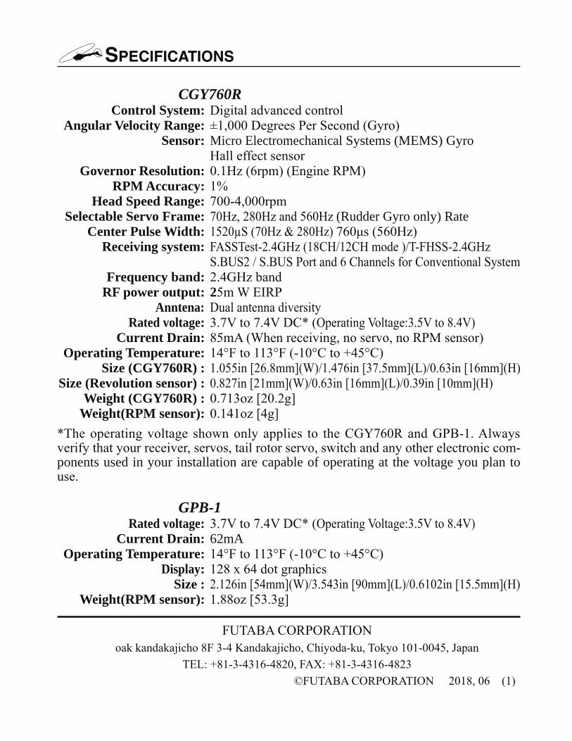
SPECIFICATIONS
CGY760R Control System: Angular Velocity Range: Sensor: Micro Electromechanical Systems (MEMS) Gyro
Governor Resolution: RPM Accuracy: Head Speed Range: Selectable Servo Frame: (Rudder Gyro only) Rate Center Pulse Width: Receiving system: Frequency band: RF power output: 2 Anntena: Rated voltage: Current Drain: Operating Temperature: Size (CGY760R) : Size (Revolution sensor) : Weight (CGY760R) : Weight(RPM sensor):
-ponents used in your installation are capable of operating at the voltage you plan to
GPB-1 Rated voltage: Current Drain: 62mA Operating Temperature: Display: Size : Weight(RPM sensor):