2. terms and definitions1 # terms and definitions # voltage sags and interruptions
TRANSCRIPT

2. Terms and definitions 1
# Terms and Definitions
# Voltage Sags and Interruptions

2. Terms and definitions 2
Definitions
• Sag (or dip) is a decrease to a low voltage (between 0.1 and 0.9 per unit rms) at power frequency for durations of 0.5 cycle to 1 minute
• Swell is an increase to a high voltage (between 1.1 and 1.8 per unit rms) at power frequency for durations of 0.5 cycle to 1 minute

2. Terms and definitions 3
Definitions
• Transient refers to an event of duration < 0.5 cycle
• Instantaneous: duration 0.5 cycle to 30 cycles
• Momentary: duration 30 cycles to 3 sec
• Temporary: duration 3 sec to 1 min.
• Sustained or long-duration: duration > 1 min.

2. Terms and definitions 4
Impulsive transient due to lightning

2. Terms and definitions 5
Shunt capacitors may be installed in substations or on poles or in enclosures

2. Terms and definitions 6
Capacitor switching

2. Terms and definitions 7
Long-duration overvoltage caused by ferroresonance of transformer

2. Terms and definitions 8
What is ferroresonance?
• Resonance of unloaded transformer (nonlinear magnetizing branch) with a capacitance
E -jXc
-jXc=1/(jC)
VL
I

2.0 Short Duration
• 2.1 Interruption

2. Terms and definitions 10
Short duration sags and swells

2. Terms and definitions 11
Temporary voltage sag caused by induction motor starting across the line

4.0 Voltage Imbalance• Voltage Imbalance

2. Terms and definitions 13
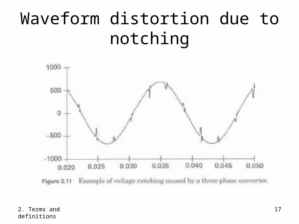
Waveform distortion• DC offset• Harmonics• Interharmonics• Notching- It is a periodic voltage disturbance
caused by the normal operation of power electronic devices when current is commuted from one phase to another.
• Noise- It is defined as unwanted electrical signals with broadband spectral content lower than 200 kHz superimposed upon the power system voltage or current in phase conductors, or found on neutral conductors or signal lines.

2. Terms and definitions 14
Harmonics

2. Terms and definitions 15
Harmonics + interharmonics

2. Terms and definitions 16
Three-phase rectifier driving DC motor
A
B
E = k mC
As VB rises above VA, current is commuted from A to B. While diode B is turning on, diode A is turning off. A is shorted to B (for a short time while both diodes conduct), producing notching.
2. Terms and definitions 17
Waveform distortion due to notching

2. Terms and definitions 18
Voltage fluctuation# Voltage magnitude does not normally exceed the
ranges of 0.9 pu to 1.1 pu.
• Series of random or continuous voltage fluctuations– Flicker is undesirable results (such as lamps
flickering) from continuous rapid variations in voltage
– Called voltage flicker (to refer to the voltage fluctuation)
– Often measured by short term flicker sensation Pst (IEC standard)

2. Terms and definitions 19
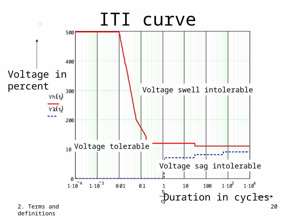
ITI (Information Technology Industry) curve
• Replaces CBEMA (Computer Business Equipment Manufacturers Association) curve
# A set of curves representing the withstand capabilities of computers in terms of the magnitude and duration of the voltage disturbance.
• Susceptibility of 120-volt computer equipment to voltage sags and swells
2. Terms and definitions 20
ITI curve
1 104
1 103
0.01 0.1 1 10 100 1 103
1 104
0
100
200
300
400
500
Vhi ti Vlo ti
ti
cy
Voltage tolerable
Voltage swell intolerable
Voltage sag intolerable
Duration in cycles
Voltage inpercent

2. Terms and definitions 21
1 106
1 105
1 104
1 103
0.01 0.1 1 10 100 1 103
0
100
200
300
400
500
Vhi ti Vlo ti
ti
s
ITI curve
Voltage tolerable
Voltage swell intolerable
Voltage sag intolerable
Voltage inpercent
Duration in sec
Voltage Sags and Interruptions

Power Transmission - Distribution System
46 kV, 69 kV,115 kV, 138 kV,161 kV, 230 kV,….
4.16 kV, 8.32 kV,12.47 kV, 13.8 kV,14.4 kV, 24.9 kV….
TRANSMISSION DISTRIBUTION

Industrial Power System
115 kV
13.8 kV
TRANSMISSION INDUSTRIAL DISTRIBUTION
Sensitive Load
Sensitive load’s own circuit
Other distribution circuits

Utility Power Distribution System
115 kV
12.47 kV
TRANSMISSIONINDUSTRIAL DISTRIBUTIONwith sensitive loads
Customer’s circuitowned by utility
Other distribution circuits
Utility Distribution System

Industrial Distribution System: Origin of Faults Causing Misoperation of Production
Equipment
23%
46%
31%Faults on OwnDistribution Circuit
Faults on OtherDistribution Circuit
Faults on TransmissionSystem

Example of typical short circuit
Fault at X:Three-phase short circuitSingle-phase to ground short
circuitPhase to phase short circuitDouble phase to ground short
circuit

Three-phase short circuit
Look at the rms value of the ac currentjust after the short-circuit occurs
The following phasor diagrams are qualitative only. Use short-circuit studyfor actual values.

Phasor diagram before the fault
Van
Vca
Vab
Vbc
Vbn
Vcn
IaIb
Ic
Normal

Three-phase short circuit
Vab
Ia
Ib Ic
Three PhaseShort Circuit

Single phase - ground short circuit
Van
Vca
Vab
Vbc
Vbn
Vcn
Ia
Single Phase to GroundShort Circuit

Phase to phase short circuit
Vca
Vab
Vbc
Ib
Phase to PhaseShort Circuit
Ic

Phase-phase-ground short circuit
Vca
Vab
VbcIb
Phase to Phaseto GroundShort Circuit
Ic