20 april 2009 aap review global design effort 1 the positron source jim clarke stfc daresbury...
TRANSCRIPT

20 April 2009 AAP Review Global Design Effort 1
The Positron Source
Jim Clarke
STFC Daresbury Laboratory

20 April 2009 AAP Review Global Design Effort 2
The Baseline Source
SLC ILC
Positrons per Bunch 3.5 x 10¹⁰ 2 x 10¹⁰
Bunches per Macropulse 1 2625
Macropulse Rep Rate (Hz) 120 5
Positrons per second 4.2 x 10¹² 2.6 x 10¹⁴

20 April 2009 AAP Review Global Design Effort 3
The Baseline SourceThe undulator based source was selected because it offered the greatest certainty of meeting the required positron source design specification. In comparison with a “conventional” source:
– Lower absorbed power in the target
– Lower target rotation speed, single target feasible
– Positron yield much less sensitive to beam size jitter on the target
– An order of magnitude fewer neutrons generated and less activation of the target system
– Positron capture more efficient due to higher phase space density
– An order of magnitude lower power dumped in the RF Capture section due to beam losses
– Lower sensitivity to DR acceptance changes
– Upgrade to polarized positrons straightforward
From the BCD

20 April 2009 AAP Review Global Design Effort 4
Non-critical Issues
• Undulator– RDR parameters demonstrated with full scale prototype
– Still work to do on alignment, etc and beam test should be carried out early in ILC build
• Collimation– Engineering needed but no show stopper expected
• Capture RF & Pre-accelerator– SW prototype constructed, challenging but feasible
• Dumps– Engineering needed but no show stopper expected
• Booster Linac– Non-standard SC modules, Engineering needed
20 April 2009 AAP Review Global Design Effort 5
Non-critical Issues
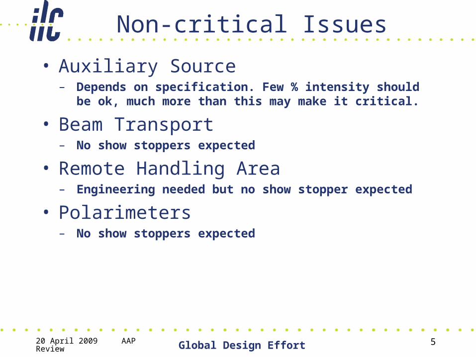
• Auxiliary Source– Depends on specification. Few % intensity should be ok, much
more than this may make it critical.
• Beam Transport– No show stoppers expected
• Remote Handling Area– Engineering needed but no show stopper expected
• Polarimeters– No show stoppers expected

20 April 2009 AAP Review Global Design Effort 6
Critical Issues• Target
– Rotating titanium wheel• Eddy current heating (~ 5kW for 1T)• Photon beam heating• Pressure shock waves• Cooling/vacuum/radiation resistance• Prototype exists and Eddy current effects will be carefully
measured and quantified/benchmarked• Analysis of pressure shock waves ongoing

20 April 2009 AAP Review Global Design Effort 7
Critical Issues• Target
– Possible alternative is Liquid metal target• Window survivability• Cavitation in liquid metal• R&D study to be carried out at KEK, including beam tests
with ATF linac (but will still need to extrapolate results)
20 April 2009 AAP Review Global Design Effort 8
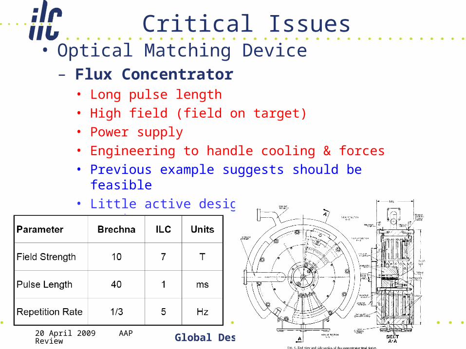
Critical Issues• Optical Matching Device
– Flux Concentrator• Long pulse length• High field (field on target)• Power supply• Engineering to handle cooling & forces• Previous example suggests should be feasible• Little active design so far for ILC but ramping up now
20 April 2009 AAP Review Global Design Effort 9
Critical Issues
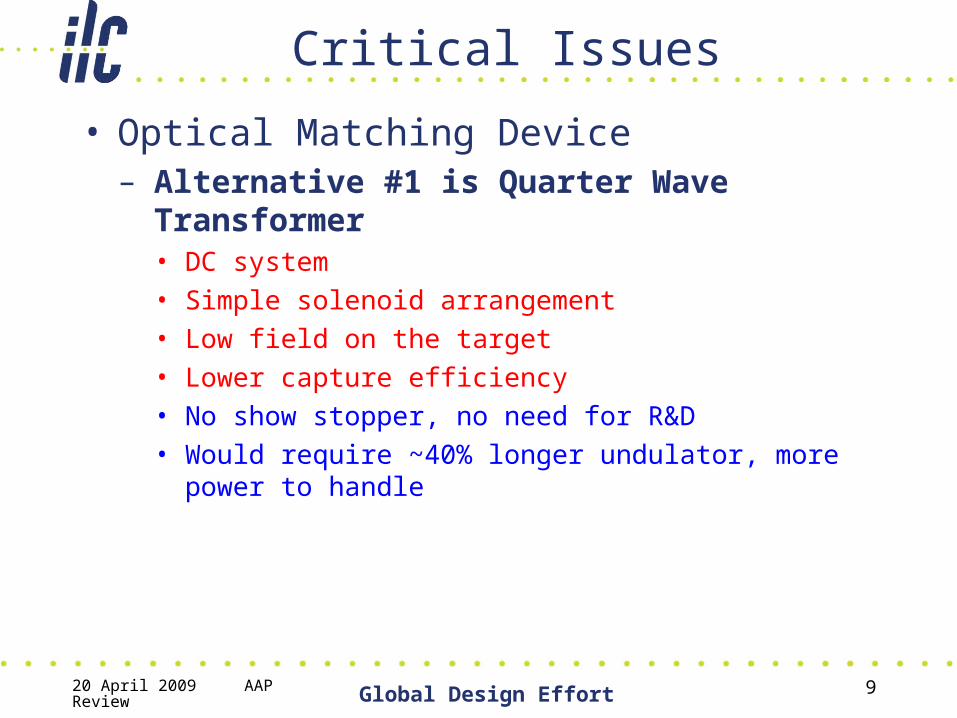
• Optical Matching Device– Alternative #1 is Quarter Wave Transformer
• DC system• Simple solenoid arrangement• Low field on the target• Lower capture efficiency• No show stopper, no need for R&D• Would require ~40% longer undulator, more power to
handle

20 April 2009 AAP Review Global Design Effort 10
Critical Issues• Optical Matching Device
– Alternative #2 is Lithium lens• Liquid metal• BN Window survivability• Cavitation in liquid metal• Design for ILC more mature than Flux Concentrator• Liquid metal target studies at KEK may help with window
& cavitation understanding
20 April 2009 AAP Review Global Design Effort 11
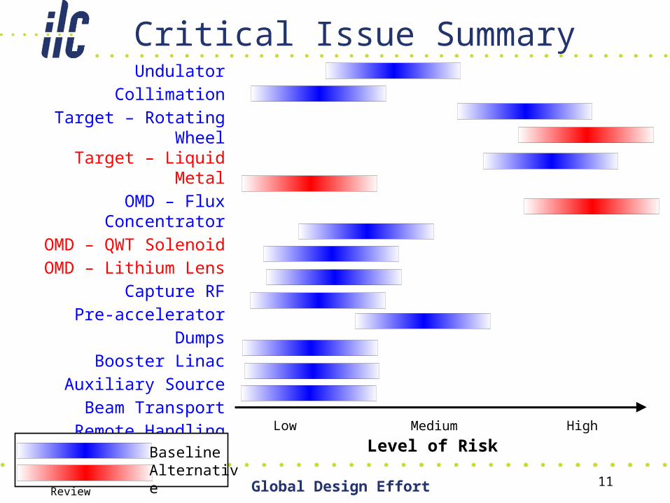
Critical Issue Summary
Level of RiskLow High
UndulatorCollimation
Target – Rotating WheelTarget – Liquid Metal
OMD – Flux ConcentratorOMD – QWT Solenoid
OMD – Lithium LensCapture RF
Pre-acceleratorDumps
Booster LinacAuxiliary SourceBeam Transport
Remote HandlingPolarimeters
Medium
BaselineAlternative
20 April 2009 AAP Review Global Design Effort 12
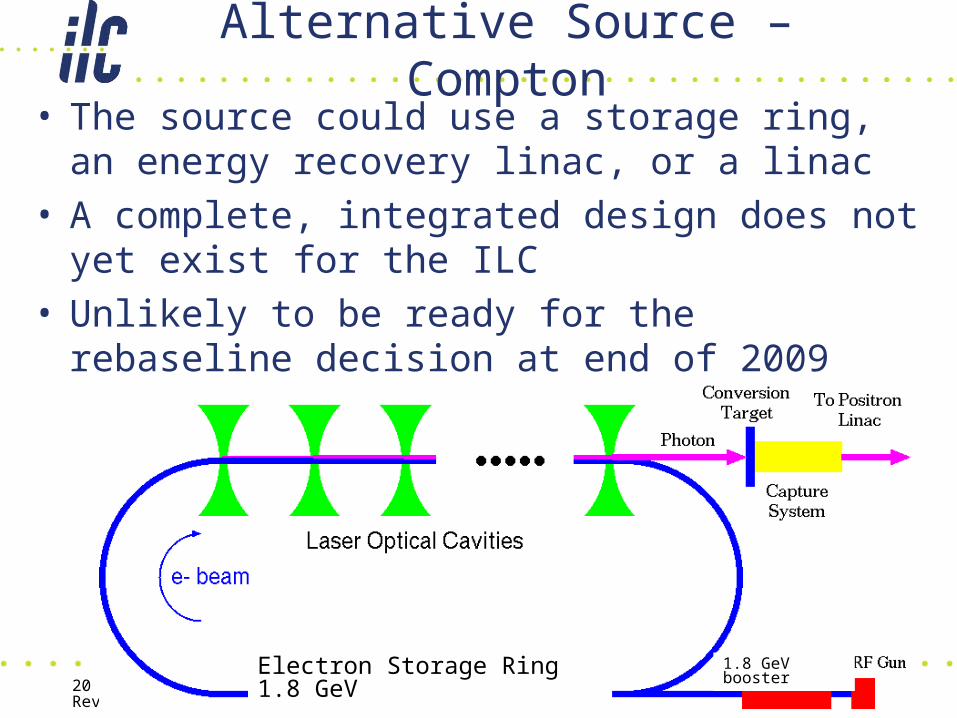
Alternative Source – Compton• The source could use a storage ring, an energy
recovery linac, or a linac• A complete, integrated design does not yet exist for
the ILC• Unlikely to be ready for the rebaseline decision at
end of 2009
Electron Storage Ring 1.8 GeV 1.8 GeV booster

20 April 2009 AAP Review Global Design Effort 13
Alternative Source – Compton
• A proof of principle experiment has been successful
• There is active R&D on the source from many collaborators
• The laser system for the ring/ERL scheme is available at the 100W level commercially
• Need ~1kW so probably not a critical issue

20 April 2009 AAP Review Global Design Effort 14
Alternative Source – Compton
• Critical Issues Highlighted Only – Laser Stacking Cavity
• High enhancement• Small laser spot• Active feedback• Small crossing angle• Active R&D plan, beam tests at ATF, plenty still to do!

20 April 2009 AAP Review Global Design Effort 15
Alternative – Compton
• Critical Issues Highlighted Only – Positron Stacking
• Have to stack to generate enough positrons per bunch• Only short time available for stacking so enough time to
damp• Increase energy pre-compression x3• Additional wigglers for faster damping x2• Larger RF voltage x 1.5• Still get ~3% injection loss• Active studies to improve this by modifying DR away from
present solution• Could add a pre-damping ring perhaps
20 April 2009 AAP Review Global Design Effort 16
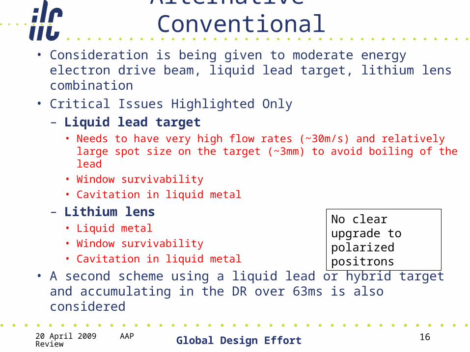
Alternative – Conventional• Consideration is being given to moderate energy electron
drive beam, liquid lead target, lithium lens combination• Critical Issues Highlighted Only
– Liquid lead target • Needs to have very high flow rates (~30m/s) and relatively large
spot size on the target (~3mm) to avoid boiling of the lead• Window survivability• Cavitation in liquid metal
– Lithium lens• Liquid metal• Window survivability• Cavitation in liquid metal
• A second scheme using a liquid lead or hybrid target and accumulating in the DR over 63ms is also considered
No clear upgrade to polarized positrons
20 April 2009 AAP Review Global Design Effort 17
Minimum Machine
• Undulator moved to the end of the linac– This allows for sharing of infrastructure with
the auxiliary source– Removal of the 1.2km insert at 150 GeV– Sharing of the tunnel (and shaft) with the BDS
• The undulator was originally placed at 150 GeV (BCD White Paper) primarily for physics reasons to maintain design luminosity over the full electron energy range

20 April 2009 AAP Review Global Design Effort 18
Minimum Machine Layout
Standard Tunnel
To DR
To IP
Remote Handling
BDS
Fast Abort Kicker
UndulatorTarget, NC Linac, Dumps
400MeV NC Linac
5GeV SC Linac
Dump
AuxiliarySource Drive
Beam
Shielding to allow access to IP when e+
running?Five separate beams in the tunnel here !
Electron RTML5GeV
BDS may have to be within remote
handling

20 April 2009 AAP Review Global Design Effort 19
Minimum Machine
• With the RDR source, running beyond 150GeV will increase the yield– gives greater safety margin and allows some
undulator modules to be turned off
• Running below 150GeV the yield will fall below 1.5 (unless more modules are installed)

20 April 2009 AAP Review Global Design Effort 20
Minimum Machine

20 April 2009 AAP Review Global Design Effort 21
Low Electron Energy Operation
• For calibration purposes (Z-pole) the auxiliary source will be able to provide intensity at the few % level
• At some energy below 150 GeV the yield will fall by a factor of two and ILC could then operate in a pulse sharing mode– Energy crossover depends on installed undulator
length– Positrons are generated at high energy but at half rep
rate– Electrons are transported at the low energy to the IP at
half rep rate– This option gives half the number of bunches at the IP

20 April 2009 AAP Review Global Design Effort 22
Low Electron Energy Operation
• Alternatively, an undulator of length sufficient for 125 GeV operation could be installed
• Then a second injector could be installed at the 125 GeV point in the linac and a bypass line– This would allow one beam to generate positrons at
125 GeV and a second beam (covering 50 to 125GeV) could be transported to the BDS
– No loss in luminosity at any energy
Electrons go through both linac sections for energies >125GeV
Electrons @ 125 GeV for undulator then dumped
Positrons
Electrons with energy 50 to 125 GeV
Linac 1 Linac 2

20 April 2009 AAP Review Global Design Effort 23
Minimum Machine
• The source needs to be re-optimised for the undulator at the end of the linac– In general we can say that above 150GeV it will
give a higher yield, the issue is how to deal with lower electron energies
• Parameter space will be examined in more detail during 2009 and operating scenarios explored
• Central region integration will also be studied to assess the impact on the CF&S, BDS, etc

20 April 2009 AAP Review Global Design Effort 24
Thanks
I would like to express my thanks to all of the positron source team for providing the
material presented here and to the AAP as background material