2.0 fatigue crack growth analysis table 6a … fatigue crack growth analysis 47 ... through crack at...
TRANSCRIPT
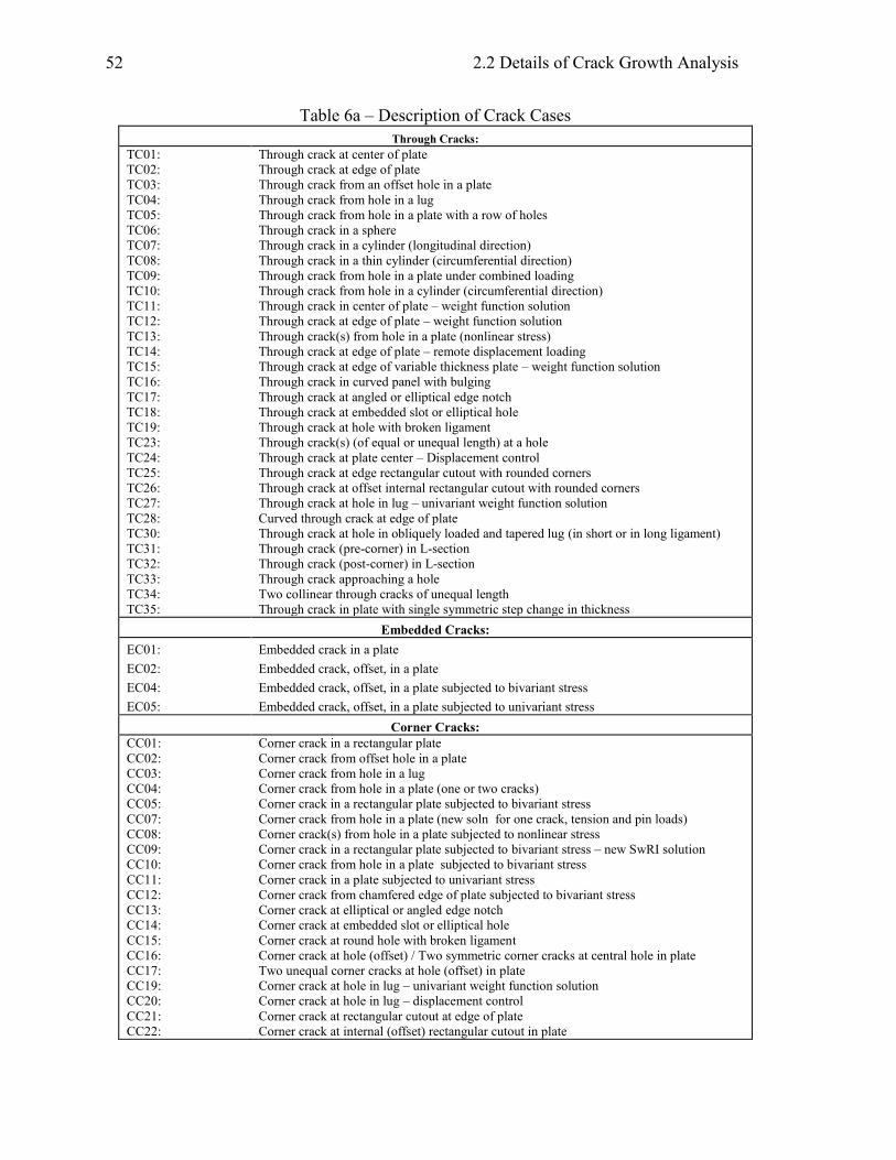
2.2 Details of Crack Growth Analysis
52
Table 6a – Description of Crack Cases
Through Cracks:
TC01:
TC02:
TC03:
TC04:
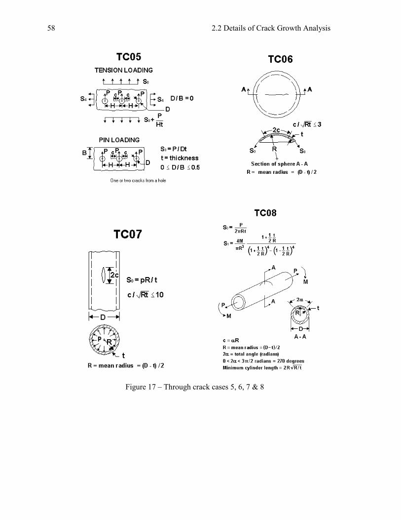
TC05:
TC06:
TC07:
TC08:
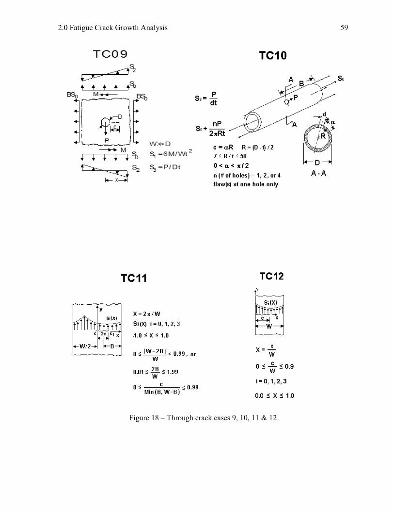
TC09:
TC10:
TC11:
TC12:
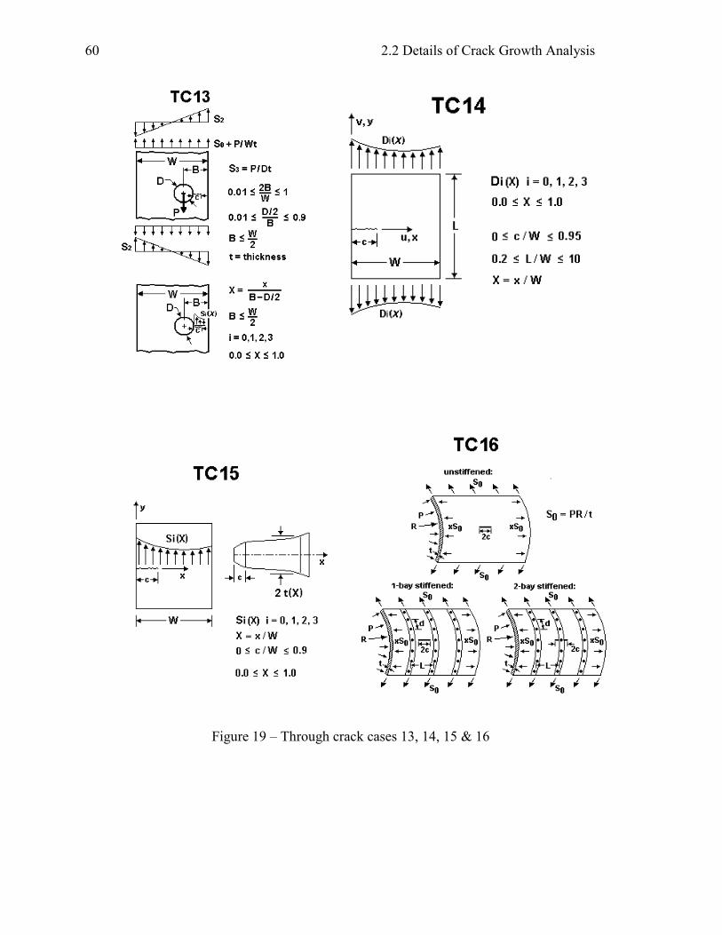
TC13:
TC14:
TC15:
TC16:
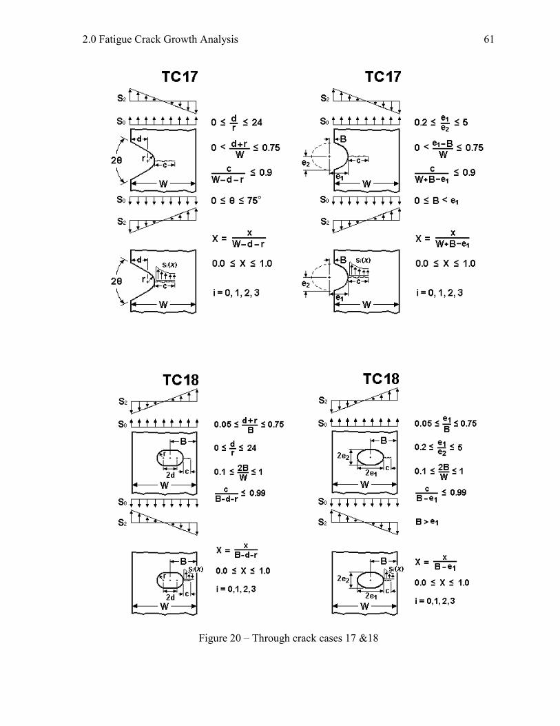
TC17:
TC18:
TC19:
TC23:
TC24:
TC25:
TC26:
TC27:
TC28:
TC30:
TC31:
TC32:
TC33:
TC34:
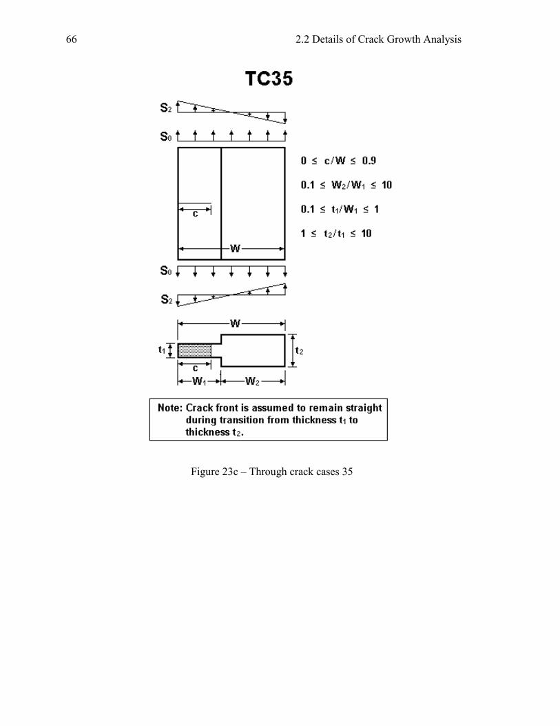
TC35:
Through crack at center of plate
Through crack at edge of plate
Through crack from an offset hole in a plate
Through crack from hole in a lug
Through crack from hole in a plate with a row of holes
Through crack in a sphere
Through crack in a cylinder (longitudinal direction)
Through crack in a thin cylinder (circumferential direction)
Through crack from hole in a plate under combined loading
Through crack from hole in a cylinder (circumferential direction)
Through crack in center of plate – weight function solution
Through crack at edge of plate – weight function solution
Through crack(s) from hole in a plate (nonlinear stress)
Through crack at edge of plate – remote displacement loading
Through crack at edge of variable thickness plate – weight function solution
Through crack in curved panel with bulging
Through crack at angled or elliptical edge notch
Through crack at embedded slot or elliptical hole
Through crack at hole with broken ligament
Through crack(s) (of equal or unequal length) at a hole
Through crack at plate center – Displacement control
Through crack at edge rectangular cutout with rounded corners
Through crack at offset internal rectangular cutout with rounded corners
Through crack at hole in lug – univariant weight function solution
Curved through crack at edge of plate
Through crack at hole in obliquely loaded and tapered lug (in short or in long ligament)
Through crack (pre-corner) in L-section
Through crack (post-corner) in L-section
Through crack approaching a hole
Two collinear through cracks of unequal length
Through crack in plate with single symmetric step change in thickness
Embedded Cracks:
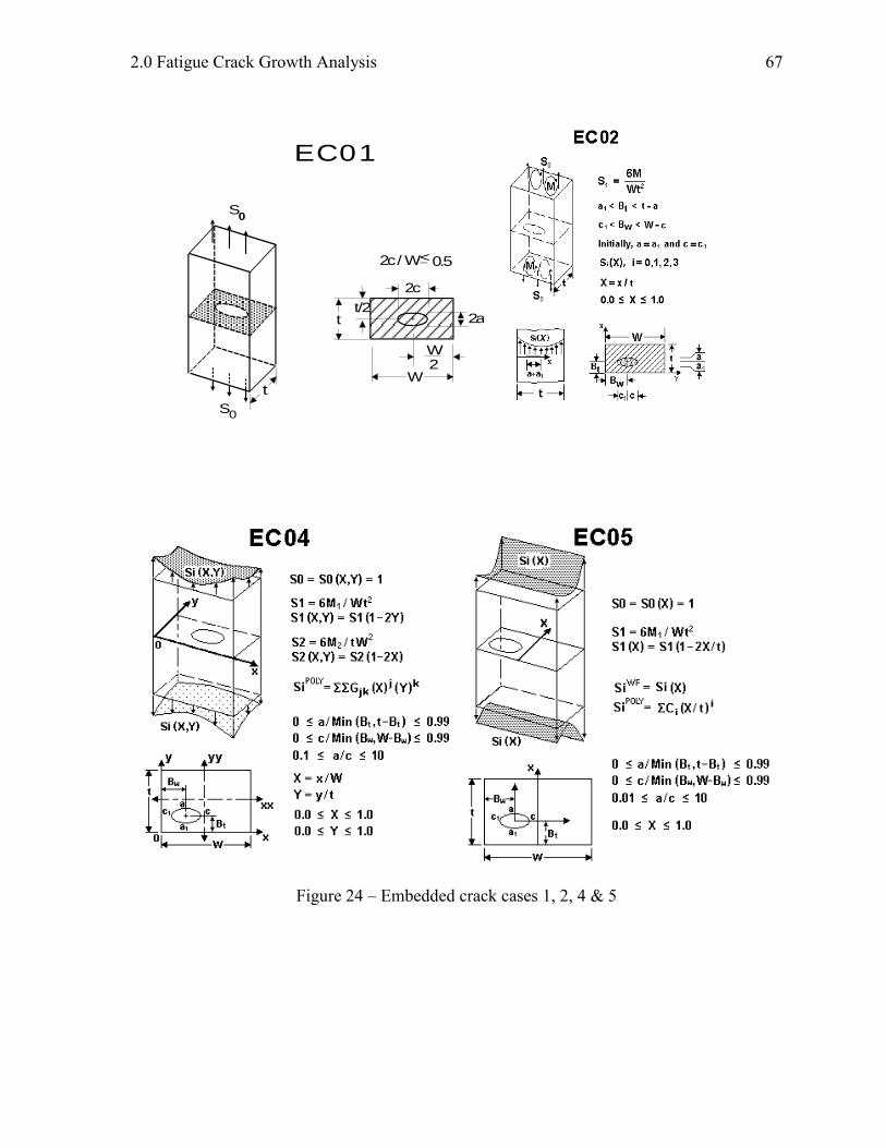
EC01:
EC02:
EC04:
EC05:
Embedded crack in a plate
Embedded crack, offset, in a plate
Embedded crack, offset, in a plate subjected to bivariant stress
Embedded crack, offset, in a plate subjected to univariant stress
Corner Cracks:
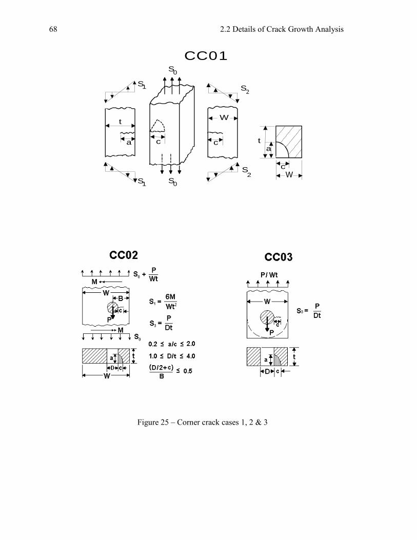
CC01:
CC02:
CC03:
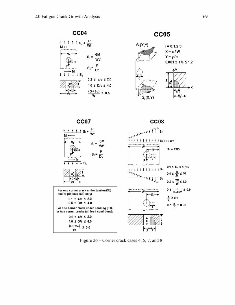
CC04:
CC05:
CC07:
CC08:
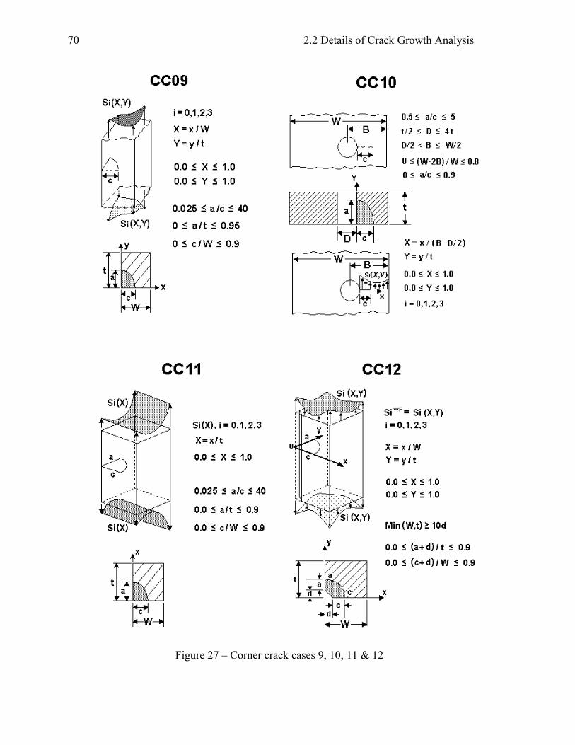
CC09:
CC10:
CC11:
CC12:
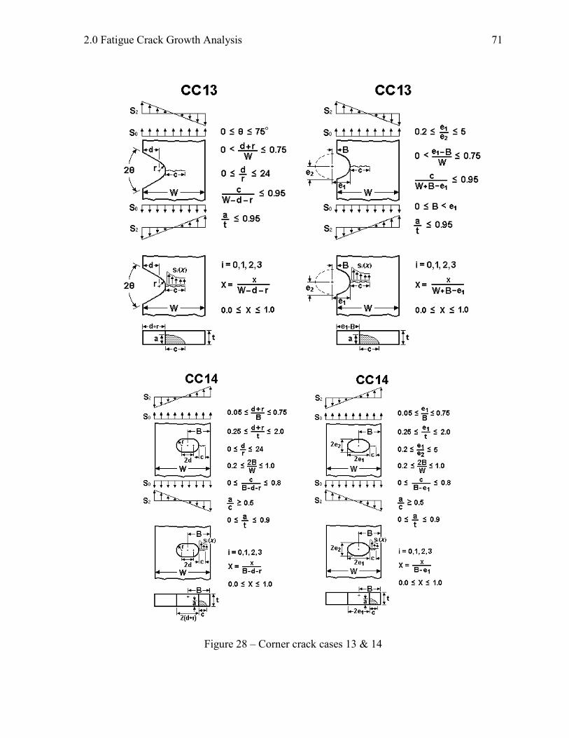
CC13:
CC14:
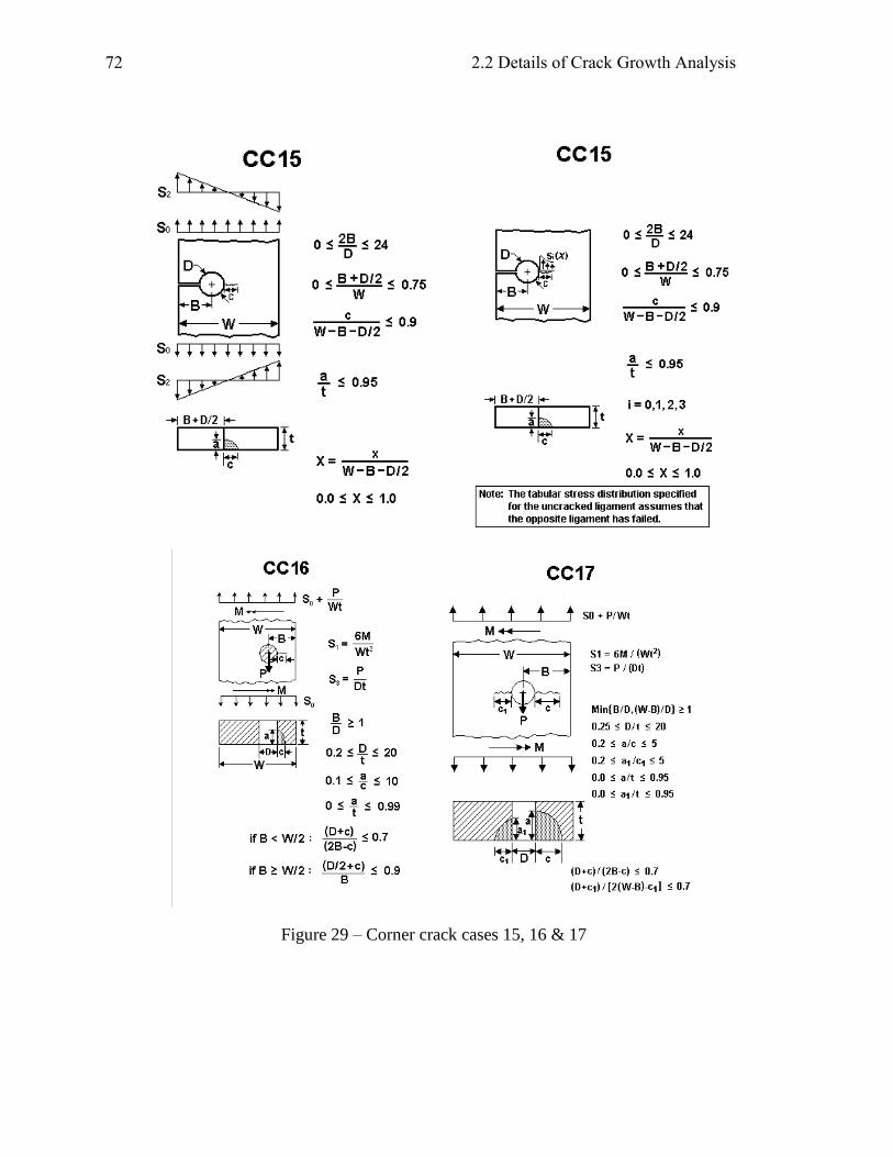
CC15:
CC16:
CC17:
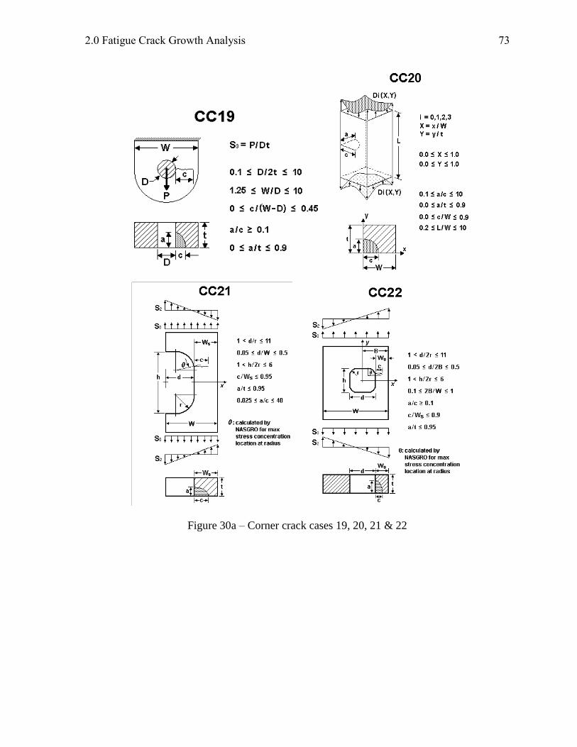
CC19:
CC20:
CC21:
CC22:
Corner crack in a rectangular plate
Corner crack from offset hole in a plate
Corner crack from hole in a lug
Corner crack from hole in a plate (one or two cracks)
Corner crack in a rectangular plate subjected to bivariant stress
Corner crack from hole in a plate (new soln for one crack, tension and pin loads)
Corner crack(s) from hole in a plate subjected to nonlinear stress
Corner crack in a rectangular plate subjected to bivariant stress – new SwRI solution
Corner crack from hole in a plate subjected to bivariant stress
Corner crack in a plate subjected to univariant stress
Corner crack from chamfered edge of plate subjected to bivariant stress
Corner crack at elliptical or angled edge notch
Corner crack at embedded slot or elliptical hole
Corner crack at round hole with broken ligament
Corner crack at hole (offset) / Two symmetric corner cracks at central hole in plate
Two unequal corner cracks at hole (offset) in plate
Corner crack at hole in lug – univariant weight function solution
Corner crack at hole in lug – displacement control
Corner crack at rectangular cutout at edge of plate
Corner crack at internal (offset) rectangular cutout in plate

2.0 Fatigue Crack Growth Analysis
53
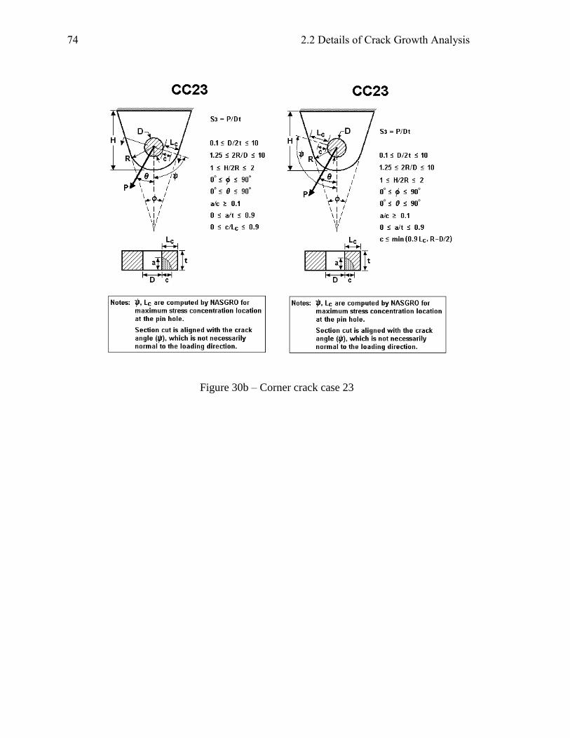
CC23: Corner crack at hole in obliquely loaded and tapered lug (in short or in long ligament)
Surface Cracks:
SC01:
SC02:
SC03:
SC04:
SC05:
SC06:
SC07:
SC08:
SC09:
SC10:
SC11:
SC12:
SC13:
SC14:
SC15:
SC17:
SC18:
SC19:
SC26:
SC27:
SC28:
SC29:
SC30:
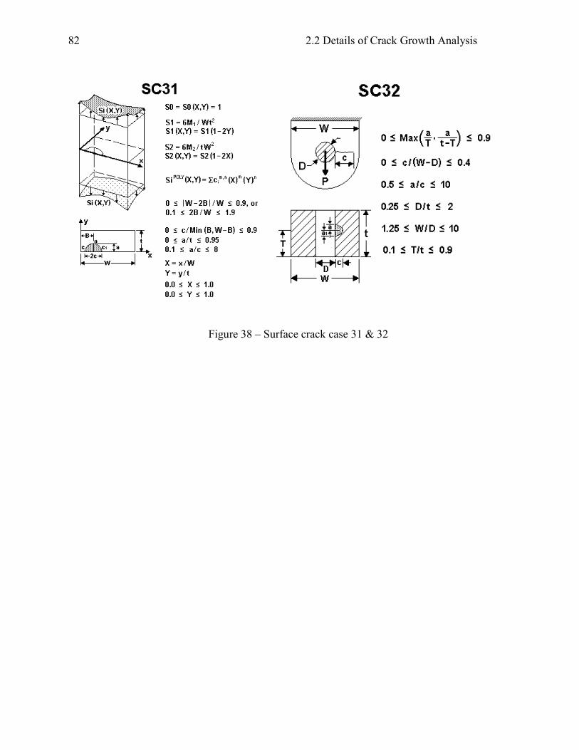
SC31:
SC32:
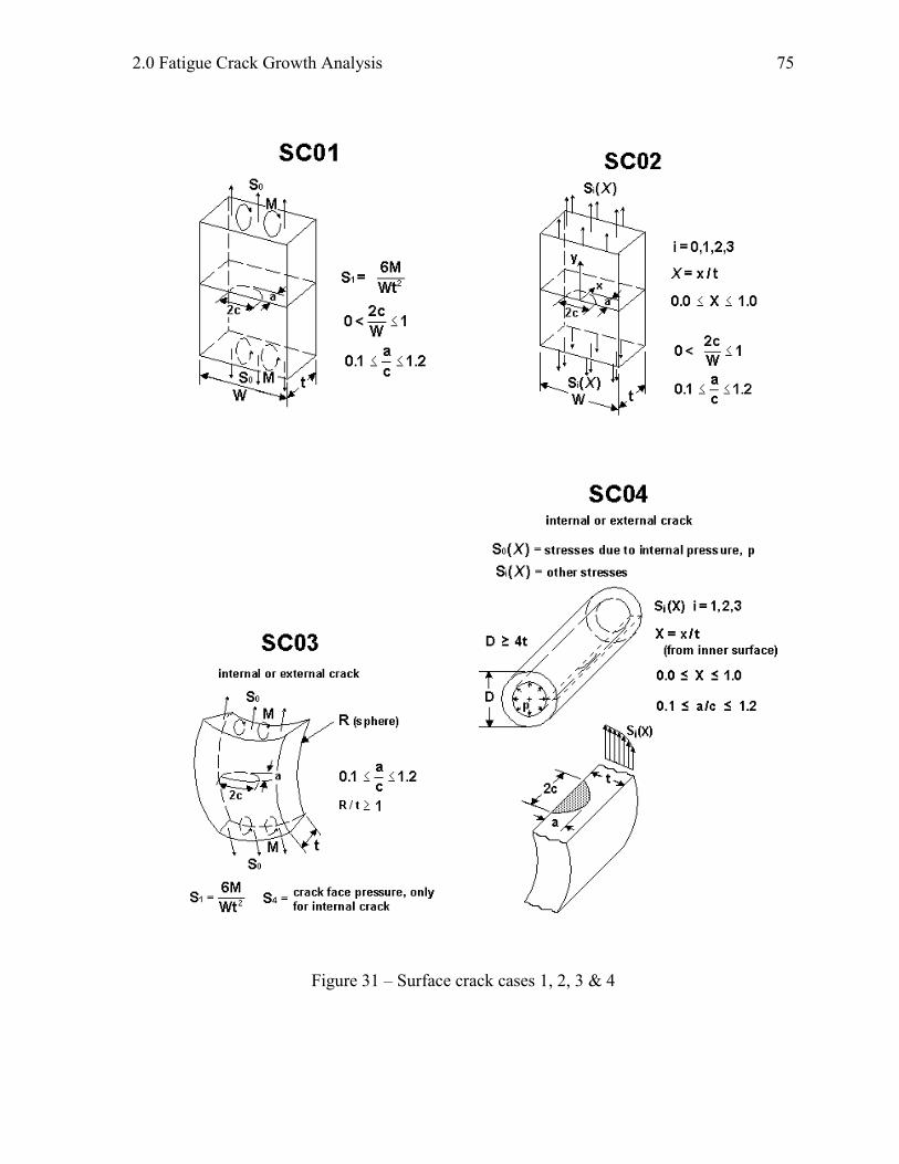
Surface crack in a rectangular plate – tension and/or bending
Surface crack in a rectangular plate – nonlinear stress
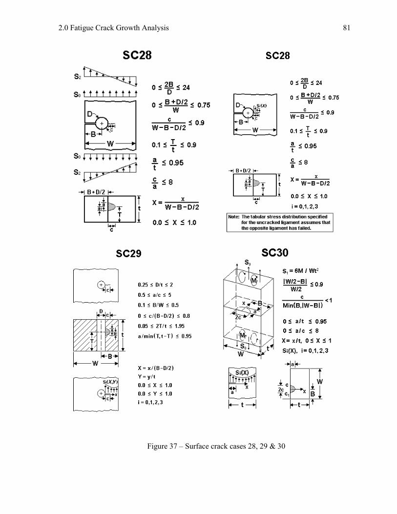
Surface crack in a spherical pressure vessel
Longitudinal surface crack in a hollow cylinder – nonlinear stress
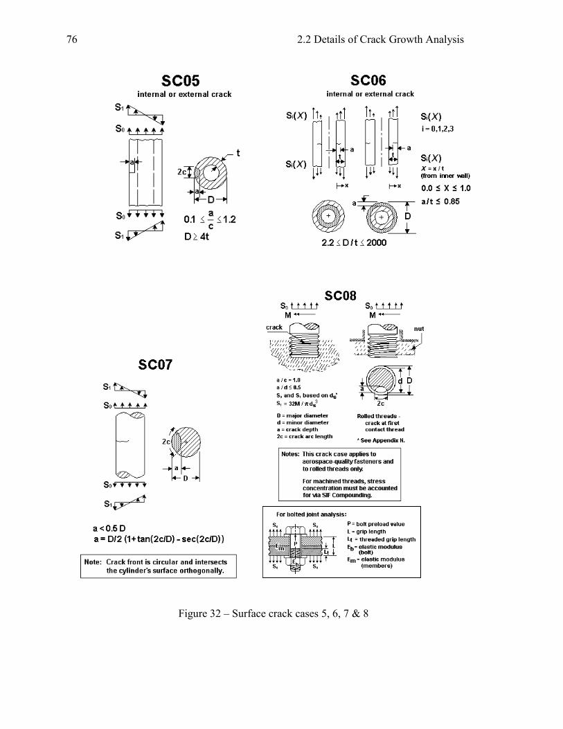
Thumbnail crack in a hollow cylinder
Circumferential crack in a hollow cylinder – nonlinear stress
Thumbnail crack in a solid cylinder
Thumbnail crack in a threaded, solid cylinder
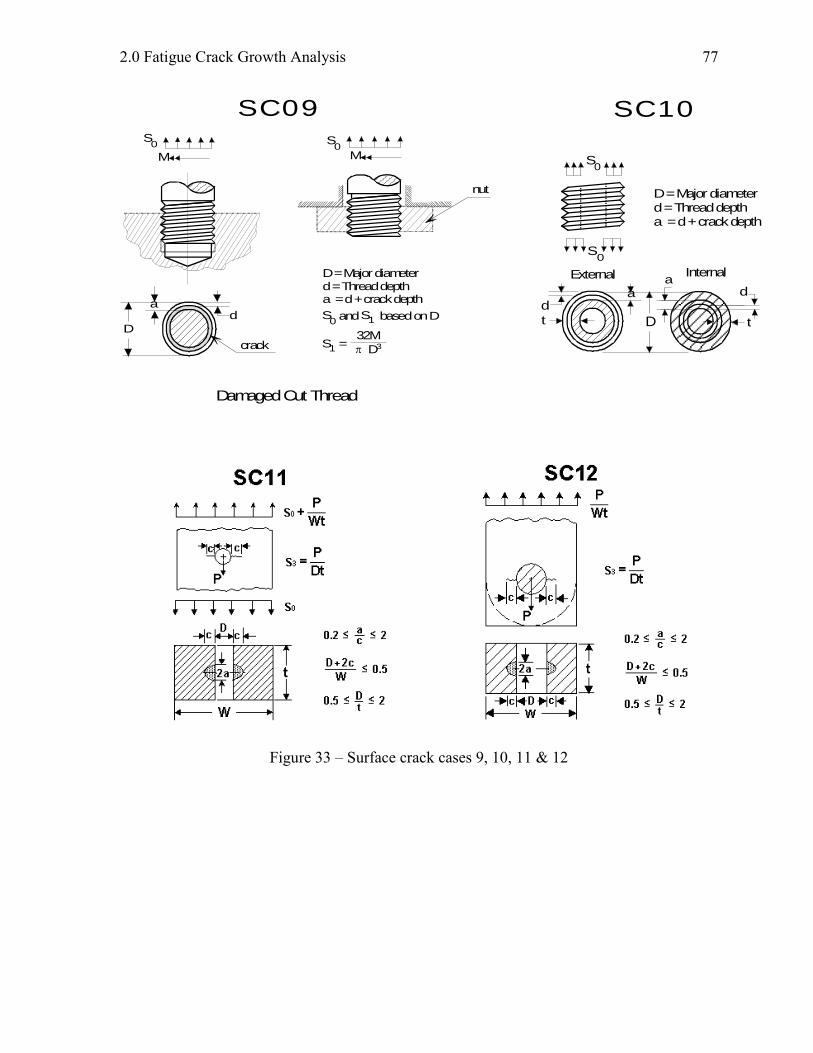
Circumferential crack at thread root in a cylinder
Circumferential crack in a threaded pipe – nonlinear stress
Surface crack from hole in a plate (one or two cracks)
Surface crack from hole in a lug (one or two cracks)
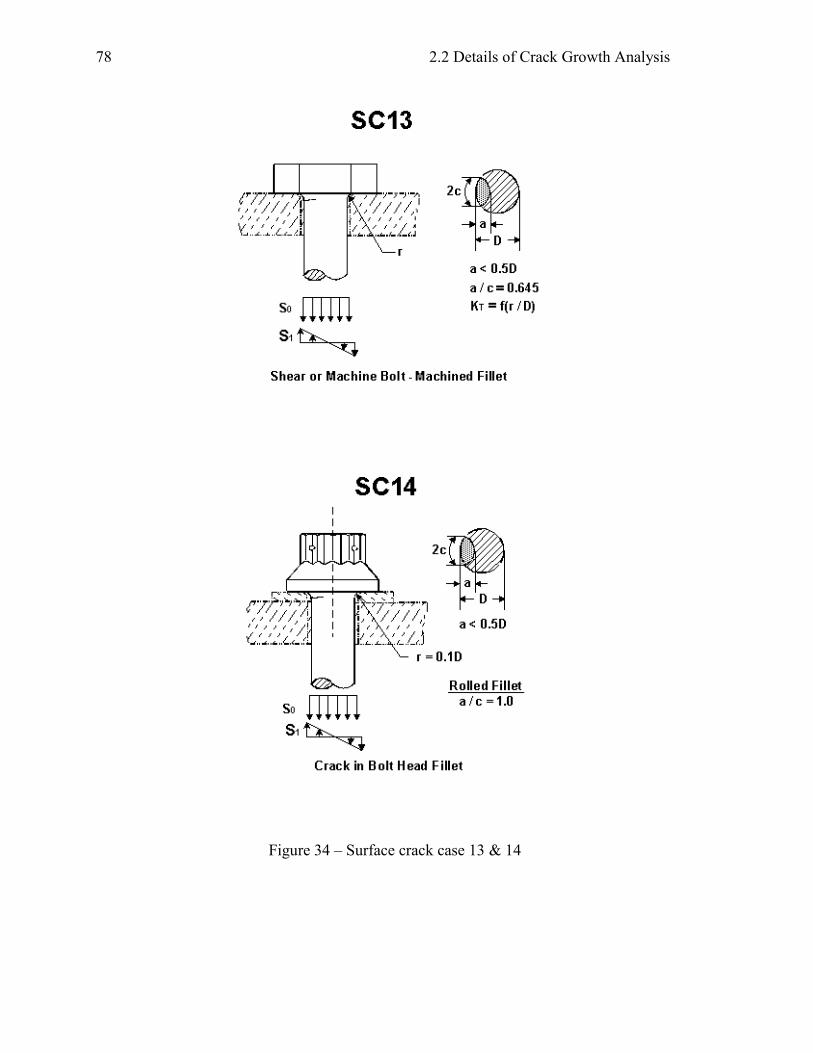
Surface crack in bolt head fillet - Shear bolt
Surface crack in bolt head fillet - Tension bolt
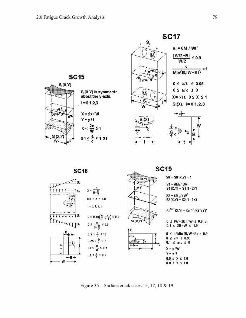
Surface crack in a plate subjected to bivariant stress
Surface crack in a rectangular plate – nonlinear stress
Surface crack(s) from hole in a plate – nonlinear stress
Surface crack in a plate, bivariant weight function solution
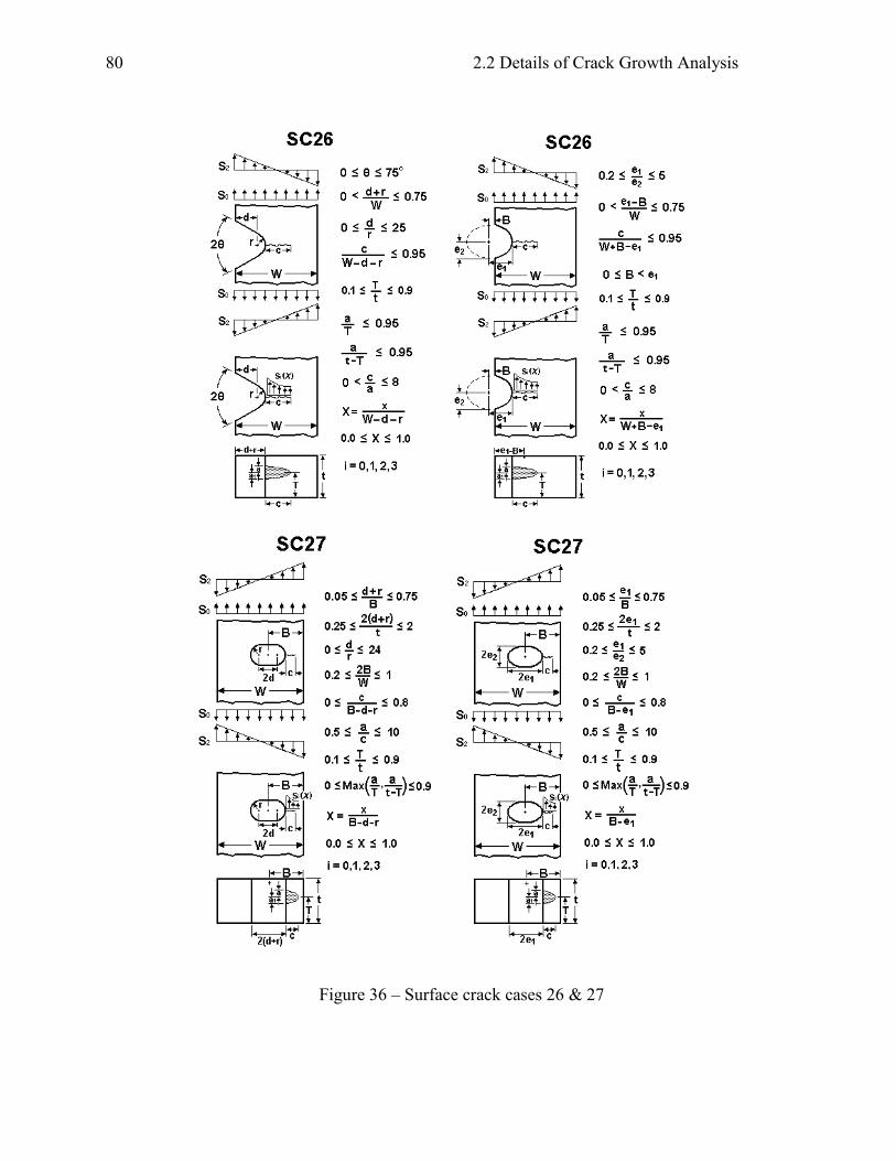
Surface crack at elliptical or angled edge notch
Surface crack at embedded slot or elliptical hole
Surface crack at round hole with broken ligament
Surface crack at off-center hole in plate - bivariant weight function solution
Surface crack (offset) in plate – univariant weight function
Surface crack (offset) in a plate – bivariant weight function solution
Surface crack at hole in lug – univariant weight function solution
Standard Specimens:
SS01:
SS02:
SS03:
SS04:
SS05:
SS06:
SS07:
SS08:
SS09:
SS10:
SS11:
SS12:
SS13:
SS14:
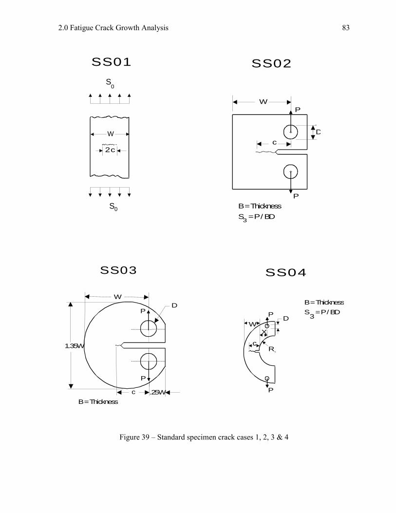
Center-cracked tension specimen M(T)
Compact tension specimen C(T)
Disc-shaped compact tension specimen DC(T)
Arc-shaped tension specimen A(T)
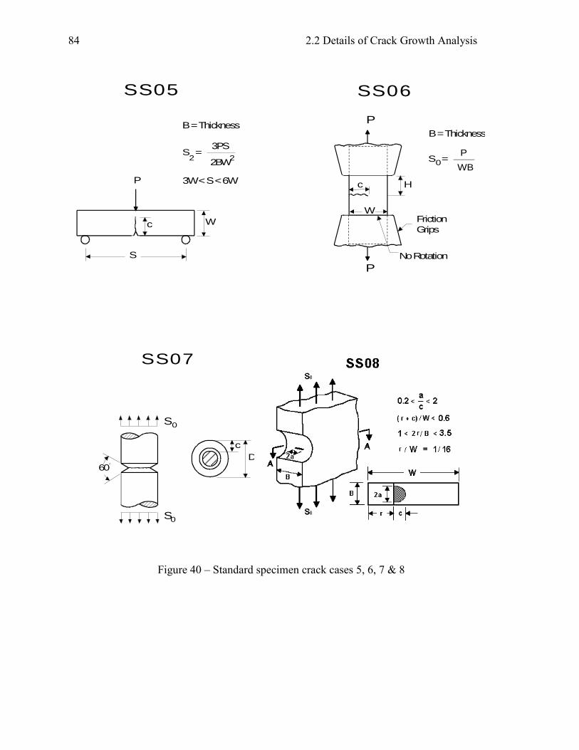
Three-point bend specimen SE(B)
Edge cracked tension specimen SE(T) – constrained ends
Notched round bar specimen R-bar(T) – circumferential crack
Notched plate with a surface crack
Notched plate with a corner crack
Notched plate with a through crack
Corner crack in a plate from symmetric hole
Eccentrically-loaded single edge crack tension specimen ESE(T)
Same as SC01, for use by NASMAT only
Same as SC17, for use by NASMAT only
Data Tables:
DT01:
DT02:
DT03:
One-dimensional data table for through cracks (one tip)
Two-dimensional data table for through cracks [hybrid & not true 2-D] (one tip)
Two-dimensional data table for part-through cracks [true 2-D] (two tips)
Stress-Intensity Factor Data Tables:
KT01:
KT02:
KT03:
One-dimensional data table for through cracks (one tip)
Two-dimensional data table for through cracks [hybrid & not true 2-D] (one tip)
Two-dimensional data table for part-through cracks [true 2-D] (two tips)
Polynomial Series:
PS01:
Boundary Element Models:
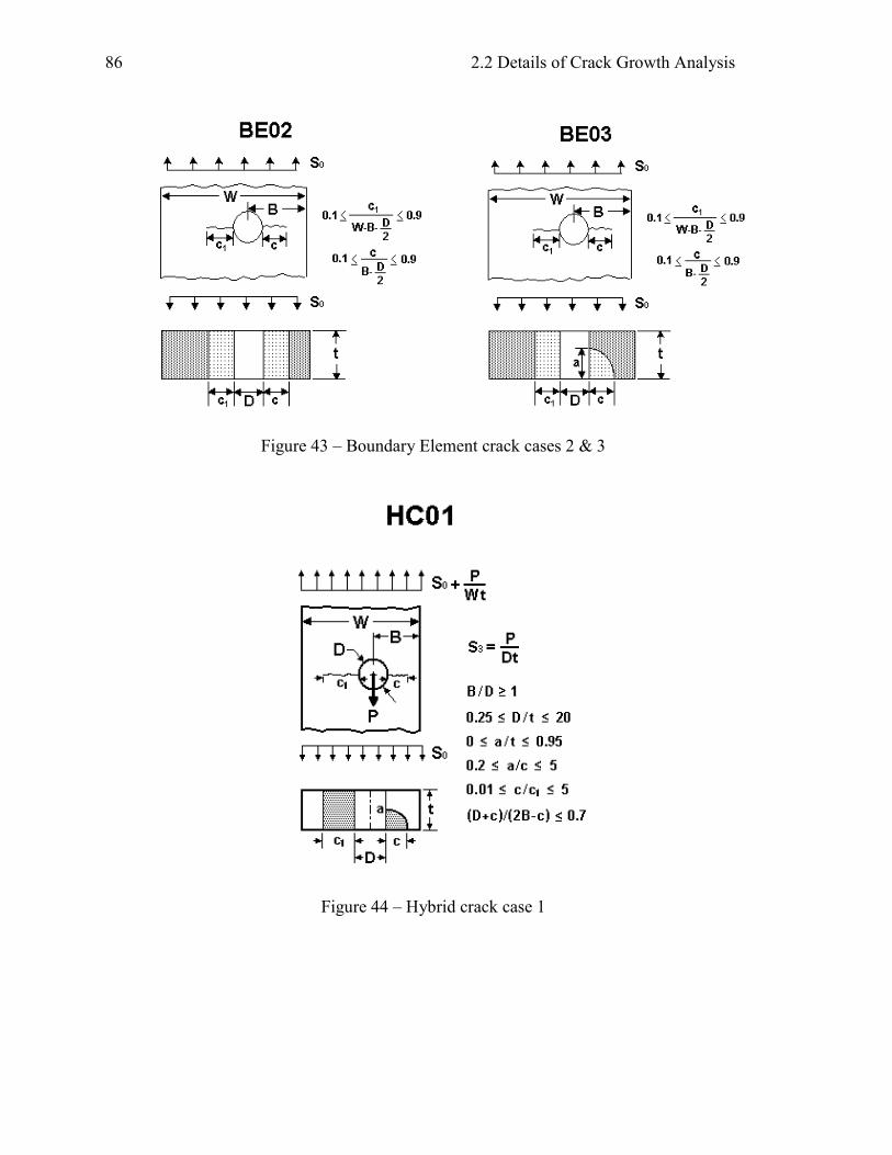
BE02:
BE03:
Two through cracks from either side of an offset hole in a plate
One through crack, one corner crack on either side of an offset hole in a plate
Hybrid Cracks
HC01 Corner crack and Through crack at (offset) hole in plate
F C C u C u C u u aD
m
0 0 1 2
2
5
5 ... where
2.2 Details of Crack Growth Analysis
54
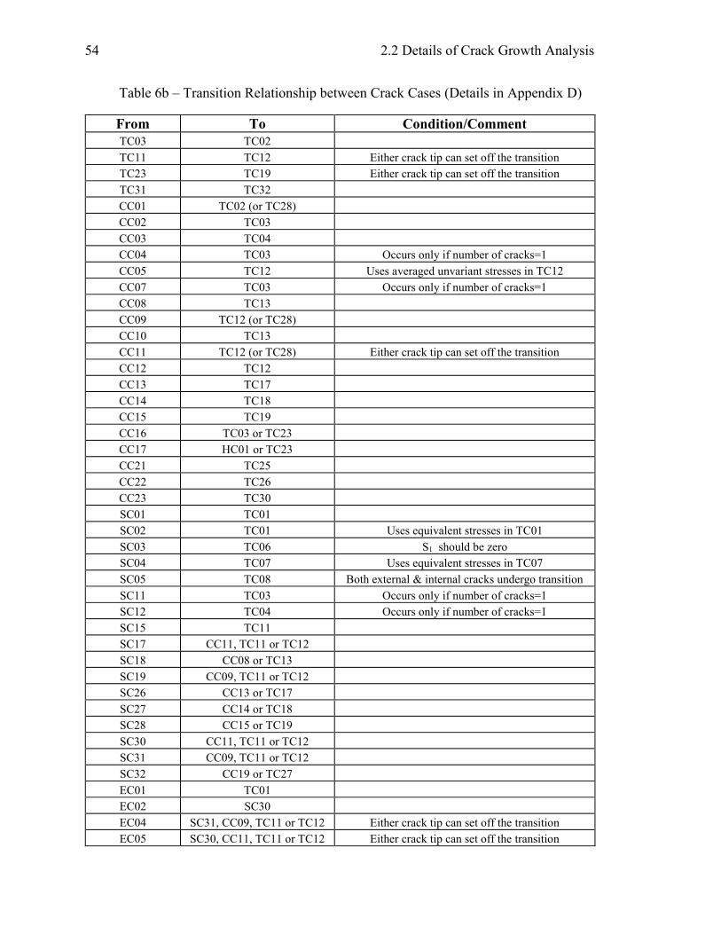
Table 6b – Transition Relationship between Crack Cases (Details in Appendix D)
From To Condition/Comment
TC03 TC02
TC11 TC12 Either crack tip can set off the transition
TC23 TC19 Either crack tip can set off the transition
TC31 TC32
CC01 TC02 (or TC28)
CC02 TC03
CC03 TC04
CC04 TC03 Occurs only if number of cracks=1
CC05 TC12 Uses averaged unvariant stresses in TC12
CC07 TC03 Occurs only if number of cracks=1
CC08 TC13
CC09 TC12 (or TC28)
CC10 TC13
CC11 TC12 (or TC28) Either crack tip can set off the transition
CC12 TC12
CC13 TC17
CC14 TC18
CC15 TC19
CC16 TC03 or TC23
CC17 HC01 or TC23
CC21 TC25
CC22 TC26
CC23 TC30
SC01 TC01
SC02 TC01 Uses equivalent stresses in TC01
SC03 TC06 S1 should be zero
SC04 TC07 Uses equivalent stresses in TC07
SC05 TC08 Both external & internal cracks undergo transition
SC11 TC03 Occurs only if number of cracks=1
SC12 TC04 Occurs only if number of cracks=1
SC15 TC11
SC17 CC11, TC11 or TC12
SC18 CC08 or TC13
SC19 CC09, TC11 or TC12
SC26 CC13 or TC17
SC27 CC14 or TC18
SC28 CC15 or TC19
SC30 CC11, TC11 or TC12
SC31 CC09, TC11 or TC12
SC32 CC19 or TC27
EC01 TC01
EC02 SC30
EC04 SC31, CC09, TC11 or TC12 Either crack tip can set off the transition
EC05 SC30, CC11, TC11 or TC12 Either crack tip can set off the transition
2.0 Fatigue Crack Growth Analysis
55
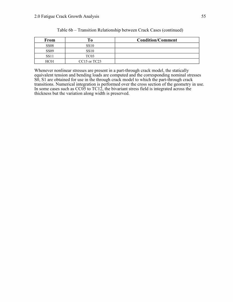
Table 6b – Transition Relationship between Crack Cases (continued)
From To Condition/Comment
SS08 SS10
SS09 SS10
SS11 TC03
HC01 CC15 or TC23
Whenever nonlinear stresses are present in a part-through crack model, the statically equivalent tension and bending loads are computed and the corresponding nominal stresses S0, S1 are obtained for use in the through crack model to which the part-through crack transitions. Numerical integration is performed over the cross section of the geometry in use. In some cases such as CC05 to TC12, the bivariant stress field is integrated across the thickness but the variation along width is preserved.

2.0 Fatigue Crack Growth Analysis
57
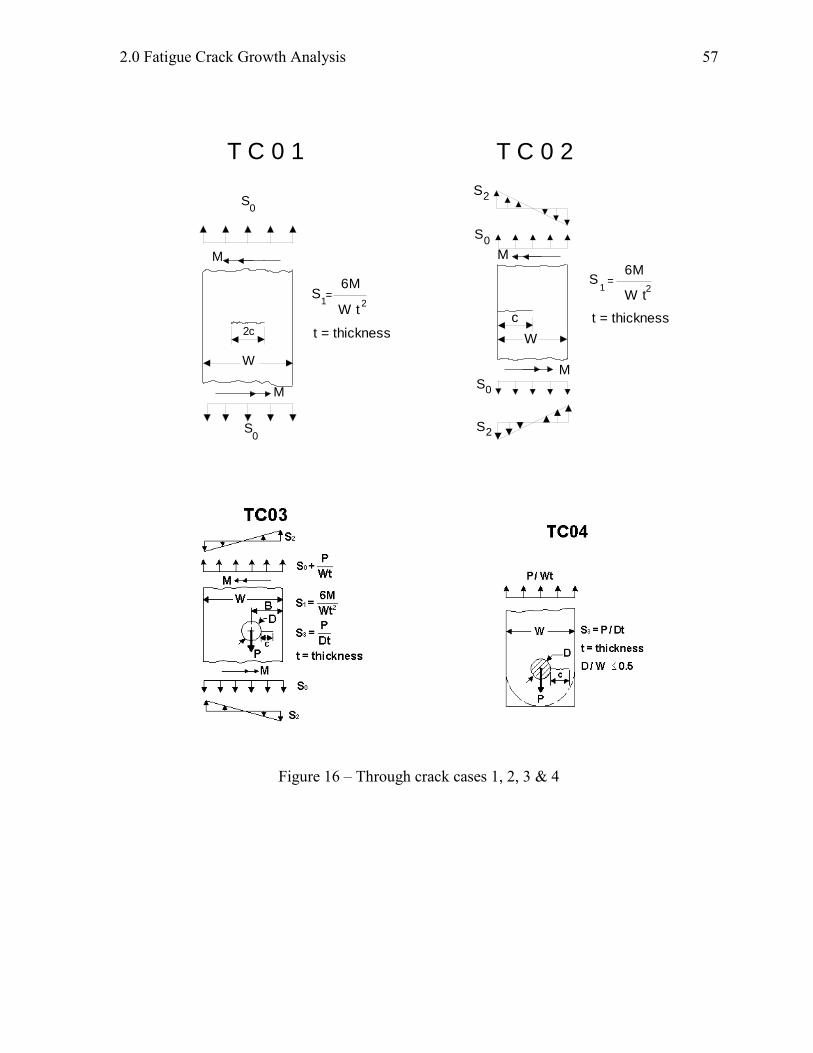
Figure 16 – Through crack cases 1, 2, 3 & 4
T C 0 1
0
M
M
W
2c
0S
S
t = thickness
6M
1S =
W t2
T C 0 2
W
c
M
M
S2
S 0
S2
S 0
t = thickness
6M
1S =
W t2
2.2 Details of Crack Growth Analysis
58
Figure 17 – Through crack cases 5, 6, 7 & 8
2.0 Fatigue Crack Growth Analysis
59
Figure 18 – Through crack cases 9, 10, 11 & 12
2.2 Details of Crack Growth Analysis
60
Figure 19 – Through crack cases 13, 14, 15 & 16
2.0 Fatigue Crack Growth Analysis
61
Figure 20 – Through crack cases 17 &18
2.2 Details of Crack Growth Analysis
62
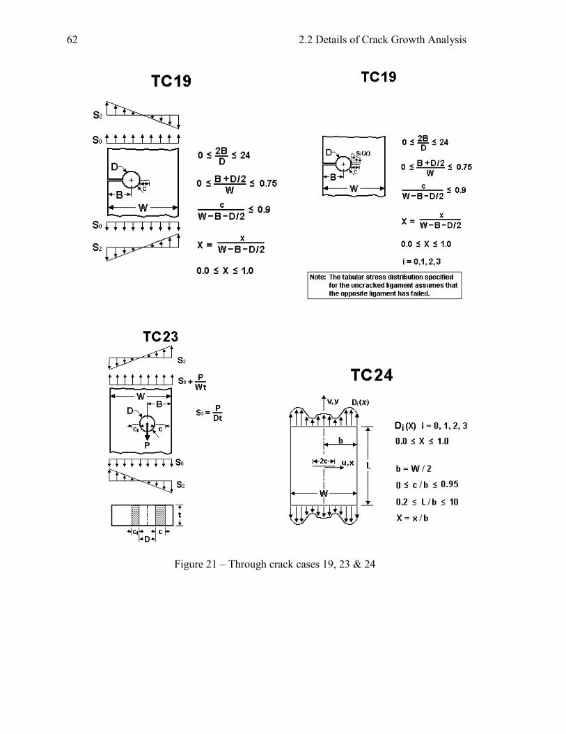
Figure 21 – Through crack cases 19, 23 & 24
2.0 Fatigue Crack Growth Analysis
63
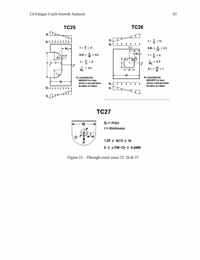
Figure 22 – Through crack cases 25, 26 & 27
2.2 Details of Crack Growth Analysis
64
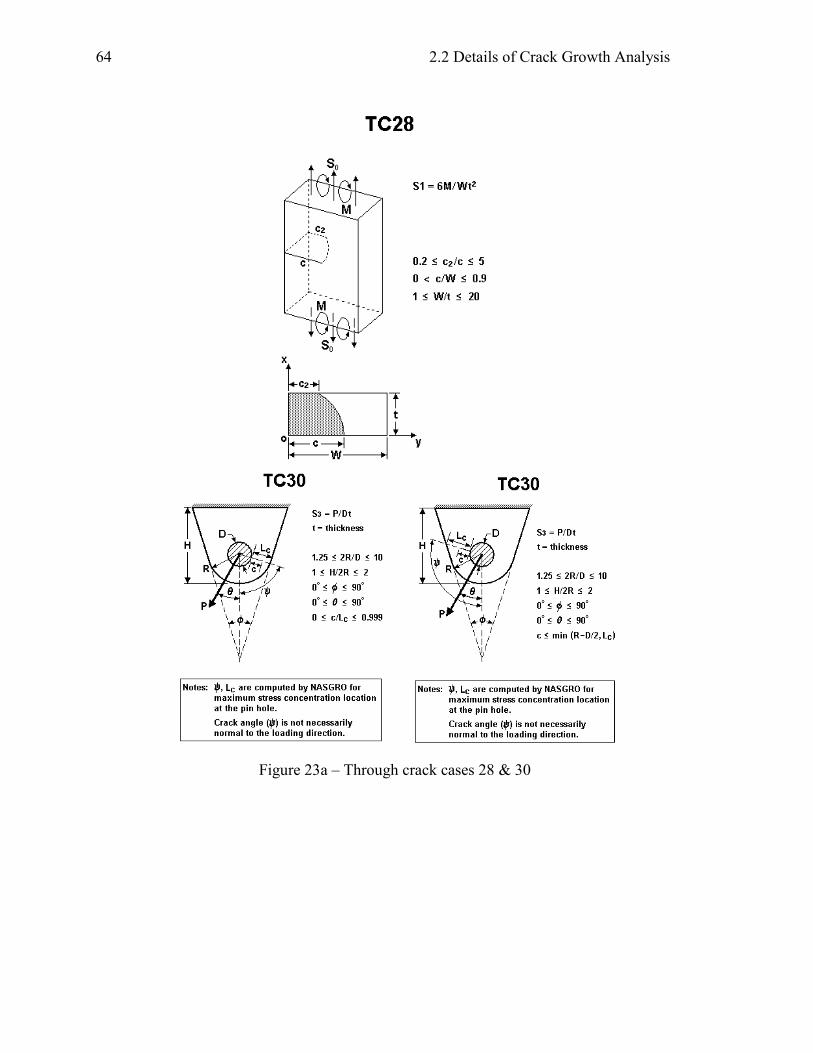
Figure 23a – Through crack cases 28 & 30
2.0 Fatigue Crack Growth Analysis
65
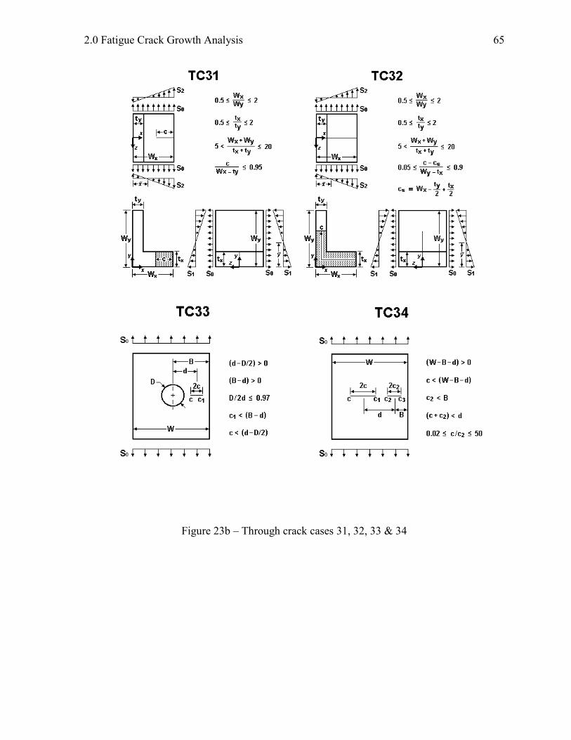
Figure 23b – Through crack cases 31, 32, 33 & 34
2.2 Details of Crack Growth Analysis
66
Figure 23c – Through crack cases 35
2.0 Fatigue Crack Growth Analysis
67
Figure 24 – Embedded crack cases 1, 2, 4 & 5
E C 0 1
t
S
S0
0
t/2t
2c
W
2a
W2
2c / W 0.5<
2.2 Details of Crack Growth Analysis
68
Figure 25 – Corner crack cases 1, 2 & 3
C C 0 1
S1S
0
t
a
W
c ca
t
cW
S2
S0
S12
S
2.0 Fatigue Crack Growth Analysis
69
Figure 26 – Corner crack cases 4, 5, 7, and 8
2.2 Details of Crack Growth Analysis
70
Figure 27 – Corner crack cases 9, 10, 11 & 12
2.0 Fatigue Crack Growth Analysis
71
Figure 28 – Corner crack cases 13 & 14
2.2 Details of Crack Growth Analysis
72
Figure 29 – Corner crack cases 15, 16 & 17
2.0 Fatigue Crack Growth Analysis
73
Figure 30a – Corner crack cases 19, 20, 21 & 22
2.2 Details of Crack Growth Analysis
74
Figure 30b – Corner crack case 23
2.0 Fatigue Crack Growth Analysis
75
Figure 31 – Surface crack cases 1, 2, 3 & 4
2.2 Details of Crack Growth Analysis
76
Figure 32 – Surface crack cases 5, 6, 7 & 8
2.0 Fatigue Crack Growth Analysis
77
Figure 33 – Surface crack cases 9, 10, 11 & 12
S C 1 0
D = Major diameterd = Thread deptha = d + crack depth
External Internal
D
a
t
d
S 0
S 0
t
da
S0
S C 0 9
Damaged Cut Thread
nut
D
da
D = Major diameterd = Thread deptha = d + crack depth
and based on DS1S0
S =1
32M
D3
M
crack
S0
M
2.2 Details of Crack Growth Analysis
78
Figure 34 – Surface crack case 13 & 14
2.0 Fatigue Crack Growth Analysis
79
Figure 35 – Surface crack cases 15, 17, 18 & 19
2.2 Details of Crack Growth Analysis
80
Figure 36 – Surface crack cases 26 & 27
2.0 Fatigue Crack Growth Analysis
81
Figure 37 – Surface crack cases 28, 29 & 30
2.2 Details of Crack Growth Analysis
82
Figure 38 – Surface crack case 31 & 32
2.0 Fatigue Crack Growth Analysis
83
Figure 39 – Standard specimen crack cases 1, 2, 3 & 4
S S 0 1
W
0S
0S
2 c
P
D
c
W
P
B = Thickness
S = P / BD3
S S 0 2
1.35W
c .25W
D
B = Thickness
W
S S 0 3
P
P
B = Thickness
S = P / BD3
P
P
R
W
X
c
D
S S 0 4
2.2 Details of Crack Growth Analysis
84
Figure 40 – Standard specimen crack cases 5, 6, 7 & 8
S =3PS
2BW22
B = Thickness
3W < S < 6W
S
P
Wc
S S 0 5
P
S S 0 6
P
W
H
No Rotation
Friction
Grips
c
B = Thickness
S = P
W B0
S S 0 7
S0
S0
60
c
D

2.0 Fatigue Crack Growth Analysis
85
Figure 41 – Standard specimen crack cases 9 & 10
Figure 42 – Standard specimen crack cases 11 & 12
2.2 Details of Crack Growth Analysis
86
Figure 43 – Boundary Element crack cases 2 & 3
Figure 44 – Hybrid crack case 1