20-sdms-01 rev. 03 (05-06-2018) - se
TRANSCRIPT

SPECIFICATION FOR OCTAGONAL STEEL POLES
Saudi Electricity Company
20-SDMS-01
REV. 03 (05-06-2018)

20-SDMS-01 REV.03
2
1. SCOPE ............................................................................................................................................................ 3
2. CROSS REFERENCES TO OTHER SEC STANDARDS ........................................................................................... 3
3. APPLICABLE CODES AND STANDARDS ........................................................................................................... 3
4. DESIGN, MATERIALS AND FABRICATION ........................................................................................................ 6
GENERAL ......................................................................................................................................................... 6 4.1.
DESIGN ........................................................................................................................................................... 6 4.2.
MATERIALS .................................................................................................................................................... 13 4.3.
FABRICATION.................................................................................................................................................. 14 4.4.
MARKING ...................................................................................................................................................... 15 4.5.
5. INSPECTION AND TESTING ........................................................................................................................... 16
INSPECTION/ROUTINE TEST REQUIREMENTS ......................................................................................................... 16 5.1.
TYPE TESTING REQUIREMENTS ............................................................................................................................ 17 5.2.
6. PACKING AND SHIPMENT ............................................................................................................................ 18
7. GUARANTEE ................................................................................................................................................ 19
8. SUBMITTALS ................................................................................................................................................ 19
9. TECHNICAL DATA SCHEDULE ....................................................................................................................... 20
10. DRAWINGS .............................................................................................................................................. 22

20-SDMS-01 REV.03
3
1. SCOPE
This specification defines the minimum technical requirements for design, engineering,
manufacture, testing, inspection and performance of octagonal steel poles intended to be used in
the distribution system of Saudi Electricity Company (SEC).
2. CROSS REFERENCES TO OTHER SEC STANDARDS
This specification shall always be read in conjunction with the latest revision of SEC
Specification No. 01-SDMS-01 titled "General Requirements for all Equipment/Materials,"
which shall be considered as an integral part of this specification. It shall also be read in
conjunction with SEC purchase order or contract schedules and scope of work/technical
specifications for projects, as applicable.
3. APPLICABLE CODES AND STANDARDS
The latest revision of the following codes and standards shall be applicable for the
equipment/materials covered in this specification. In case of any deviation, the
vendor/manufacturer may propose equipment/materials conforming to alternate codes or
standards. However, the provisions of SEC standards shall supersede the provisions of the
alternate standards in case of any difference.
Table 1: List of applicable standards
Standard # Title
AISC Manual of Steel Construction, 14th Edition
ASCE 48-11 Design of Steel Transmission Pole Structures
ASTM A36M Standard Specification for Carbon Structural Steel
ASTM A123 Standard Specification for Zinc (Hot-Dip Galvanized) Coatings of Iron and
Steel Products
ASTM A143
Standard Practice for Safeguarding Against Embrittlement of Hot-Dip
Galvanized Structural Steel Products and Procedure for Detecting
Embrittlement

20-SDMS-01 REV.03
4
Standard # Title
ASTM A153 Standard Specification for Zinc Coating (Hot-Dip) on Iron and Steel
Hardware
ASTM A215 Martensitic Stainless Steel and Alloy Steel Castings for Pressure Containing
Parts Suitable for High Temperature Service
ASTM A239 Standard Test Method for Locating the Thinnest Spot in a Zinc (Galvanized)
Coating on Iron or Steel Articles by the Preece Test (Copper Sulfate Dip)
ASTM A307 Standard Specification for Carbon Steel Bolts and Studs, 60000 PSI Tensile
Strength
ASTM A320 Alloy-Steel Bolting Materials for Low Temperature
ASTM A351 Austenitic Steel Castings for High Temperature Service
ASTM A325 Standard Specification for Structural Bolts, Steel, Heat-Treated, 120/105 PSI
Minimum Tensile Strength
ASTM A354 Standard Specification for Quenched and Tempered Alloy Steel Bolts, Studs
and Other Externally Threaded Fasteners
ASTM A370 Standard Test Methods and Definitions for Mechanical Testing of Steel
Products
ASTM A384 Standard Practice for Safeguarding Against Warpage and Distortion During
Hot-Dip Galvanizing of Steel Assemblies
ASTM A385 Standard Practice for Providing High Quality Zinc Coatings (Hot-Dip)
ASTM A394 Standard Specification for Carbon and Alloy Steel Nuts
ASTM A490 Quenched and Tempered Alloy Steel Bolts for Structural Steel Joints
ASTM A537 Pressure Vessel Plates, Heat Treated, Carbon-Manganese-Silicon
ASTM A572 High-Strength Low-Alloy Columbium-Vanadium Steels of Structural Quality
ASTM A577M Standard Specification for Ultrasonic Angle Beam Examination of Steel
Plates
ASTM A578M Standard Specification for Ultrasonic Straight Beam Examination of Plain
and Clad Steel Plates for Special Application
ASTM A588 Standard Specification for High-Strength Low-Alloy Structural Steel with
50Ksi (345Mpa) Minimum Yield Point to 4-inch (100mm) Thick

20-SDMS-01 REV.03
5
Standard # Title
ASTM A633 Standard Specification for Normalized High-Strength Low-Alloy Structural
Steel Plates
ASTM A673 Standard Specification for Sampling Procedure for Impact Testing of
Structural Steel
ASTM A687 Standard Specification for High-Strength Non-Headed Steel Bolts and Studs
ASTM E165 Standard Test Method for Liquid Penetrant Examination
ASTM E709 Standard Guide for Magnetic Particle Examination
AWS D1.1 Structural Welding Code, Steel
AWS D10.9 Specification for Qualification of Welding Procedures and Welders for Piping
and Tubing
ISO 630 Standards for Structural Steels
ISO R657 Recommendation for Hot-Rolled Steel Sections
ISO 1459 Metallic Coatings - Protection Against Corrosion by Hot Dip Galvanizing -
Guiding Principles
ISO 1460 Metallic Coatings - Hot-Dip Galvanized Coatings on Ferrous Materials -
Gravimetric Determination of the Mass per Unit Area
ISO 1461 Metallic Coatings - Hot Dip Galvanized Coatings on Fabricated Ferrous
Products – Requirements
ISO 3575 Continuous Hot-Dip Zinc-Coated Carbon Steel Sheet of Commercial, Lock-
Forming and Drawing Qualities
ISO 4997 Cold-Reduced Steel Sheet of Structural Quality
ISO 4998 Continuous Hot-Dip Zinc-Coated Carbon Steel Sheet of Structural Quality
ISO 7413 Hexagon Nuts for Structural Bolting, Style 1, Hot-Dip Galvanized (Oversize
Tapped) - Product Grades A and B - Property Classes 5, 6 and 8
ISO 7417 Hexagon Nuts for Structural Bolting - Style 2, Hot-Dip Galvanized (Oversize
Tapped) - Product Grade A - Property Class 9
SASO/SSA 39 Mechanical Testing of Welded Joints
SASO/SSA 107 Tensile Steel Testing
SASO/SSA 157 Charpy Method of Impact Test on Metals

20-SDMS-01 REV.03
6
4. DESIGN, MATERIALS AND FABRICATION
GENERAL 4.1.
The galvanized octagonal steel poles shall be a single-piece of required length. Their cross
sectional shapes shall be tapered octagonal and conform to dimensions given in the tables and
drawings in this specification.
The octagonal steel poles shall satisfy the dimensional length and pole top loading requirements
as per the design parameters listed in Table-1, Table-4, and Table-5. The dimensions across the
flats for top and bottom for all poles as listed in Table-1 are a preferred design to utilize one
dimension for each type of pole.
Designated holes shall be pre-drilled and then capped UV resistant plastic plugs.
DESIGN 4.2.
4.2.1. Types, dimensions and characteristics of standard steel poles included in this
specification are given in Table-1.
4.2.2. Applications of the standard steel poles are given in Tables-2 and Table-3.
4.2.3. The standard poles shall be suitable for the specified applications based on the
design parameters given in Tables-4 and Table-5.
4.2.4. Poles are designed to withstand the worst possible combination of simultaneous
loading of:
Lateral loads consisting of wind forces on conductors corresponding to wind
spans, wind force on insulators, wind force on pole and maximum conductor
tension.
Vertical loads consisting of pole self-weight, weights of conductors, insulators,
cross-arm, pole-mounted equipment, lineman and compressive force due to
reaction of stays wherever applicable.
4.2.5. The maximum design unit stress shall not exceed the minimum yield stress as stated
in this specification for the particular application and types of loads, including
overload capacity factors.

20-SDMS-01 REV.03
7
4.2.6. For prequalification purposes or as requested by SEC, the following shall be
submitted to verify conformance of the octagonal steel poles with the requirements
specified in this specification and related standards:
a. Mill Tests Reports and Certificates specifying conformance of materials with
applicable standards.
b. Computer-based design calculation and simulations on various loading
scenarios and structure type per SEC construction standards including SEC
equipment specifications and ratings.
c. Full Audit Report from approved independent third-party inspector witnessed
by SEC.
d. Type test report and certificates.
e. AutoCAD drawings in (*.dwg) digital format, 2013 version.
f. Capacity and layout of octagonal steel pole test facility.
g. Capacities and capabilities of all equipment used to manufacture the poles.
h. E-copy of the above documents in USB Flash Drive.
20-SDMS-01 REV.03
8
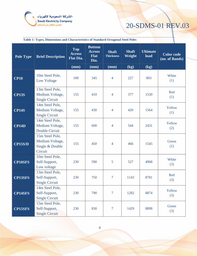
Table 1: Types, Dimensions and Characteristics of Standard Octagonal Steel Poles
Pole Type Brief Description
Top
Across
Flat Dia.
Bottom
Across
Flat
Dia.
Shaft Thickness
Shaft
Weight
Ultimate
load Color code
(no. of Bands)
(mm) (mm) (mm) (kg) (kg)
CP10 10m Steel Pole,
Low Voltage 100 345 4 227 803
White
(1)
CP13S
13m Steel Pole,
Medium Voltage,
Single Circuit
155 410 4 377 1530 Red
(1)
CP14S
14m Steel Pole,
Medium Voltage,
Single Circuit
155 430 4 420 1564 Yellow
(1)
CP14D
14m Steel Pole,
Medium Voltage,
Double Circuit
155 600 4 544 2431 Yellow
(2)
CP15S/D
15m Steel Pole,
Medium Voltage,
Single & Double
Circuit
155 450 4 466 1545 Green
(1)
CP10SFS
10m Steel Pole,
Self-Support,
Low voltage
230 590 5 527 4968 White
(3)
CP13SFS
13m Steel Pole,
Self-Support,
Single Circuit
230 750 7 1143 8781 Red
(3)
CP14SFS
14m Steel Pole,
Self-Support,
Single Circuit
230 790 7 1282 8874 Yellow
(3)
CP15SFS
15m Steel Pole,
Self-Support,
Single Circuit
230 830 7 1429 8898 Green
(3)

20-SDMS-01 REV.03
9
Table 2: Applications of Standard Octagonal Steel Poles for Single Circuit Lines
Pole Type Pole Structure
Angle of
Deviation
No. of
Stays/Location
From Top
Buried
Depth
Crossarm
Location From
Top
(Degrees) (mm) (mm) (mm)
CP10
Intermediate, LV 0-15 N/A 1500 N/A
Medium angle, LV 16-60 1@150 1500 N/A
Heavy angle, LV 61-90 1@150 1500 N/A
Terminal, LV - 1@150 1500 N/A
CP13S
CP14S
CP15S/D
Intermediate, MV 0-5 N/A 2000 50
Light angle, MV 6-15 1@250 2000 50
Medium angle, MV 16-60 1@250 &
1@350 2000 50
Heavy angle, MV 61-90 1@250 &
1@350 2000 50
Section, MV - 2@250
along the line 2000 50
Terminal, MV - 1@250 &
1@350 2000 50
CP10SFS* Self-Support, LV 16-90 N/A 1500 N/A
CP13SFS*
Self-Support, MV 6-90 N/A 2000 50 CP14SFS*
CP15SFS*
* For the installation of the above specified angles without guy support.

20-SDMS-01 REV.03
10
Table 3: Applications of Standard Octagonal Steel Poles for Double Circuit Lines
Pole Type Pole Structure
Angle of
Deviation
No. of
Stays/Location
from Top
Buried
Depth
Cross arm
Location From
Top
(Degrees) (mm) (mm) (mm)
CP14D
Intermediate, MV 0-5 N/A 2000 50, 1250 & 2450
Light Angle, MV 6-15 1@250 & 1@350 2000 50, 1250 & 2450
Medium Angle, MV 16-60 1@250 & 1@350,
1@2650 & 1@2750 2000 50, 1250 & 2450
Heavy Angle, MV 61-90 1@250 & 1@350,
1@2650 & 1@2750 2000 50, 1250 & 2450
Section, MV - 2@250 & 2@2650
along the line 2000 50, 1250 & 2450
Terminal, MV - 1@250, 1@350,
1@2650 & 1@2750 2000 50, 1250 & 2450
CP15S/D
Intermediate, MV 0 N/A 2000 50, 1250 & 2450
Light Angle, MV 1-15 1@250 & 1@350 2000 50, 1250 & 2450
Medium Angle, MV 16-60 1@250 & 1@350,
1@2650 & 1@2750 2000 50, 1250 & 2450
Heavy Angle, MV 61-90 1@250 & 1@350,
1@2650 & 1@2750 2000 50, 1250 & 2450
Section, MV - 2@250 & 2@2650
along the line 2000 50, 1250 & 2450
Terminal, MV - 1@250, 1@350,
1@2650 & 1@2750 2000 50, 1250 & 2450

20-SDMS-01 REV.03
11
Table 4: Design Parameters for Single Circuit LV and MV (with Earth-Wire) Line
Description 10m 13m, 14m and 15m
Span (m)
Basic 50 100
Wind 55 110
Weight 75 150
Wind pressure
(N/m2)
On pole 1200 1200
On conductors at 10°C 600 600
Factor of Safety
Vertical loads 1.5 1.5
Transverse loads 1.5 1.5
Longitudinal loads 1.5 1.5
Ultimate load
Conductor minimum
breaking strength 3.0 3.0
Planting Depth (m) 1.5 2.0
Types of structure
Unstayed Intermediate (0-15°) Intermediate (0-15°)
Stayed - Light angle (6-15°)
Stayed Med. angle (16-60°) Med. angle (16-60°)
Stayed Heavy angle (60-90°) Heavy angle (61-90°)
Stayed - Section
Stayed Terminal Terminal
Unstayed Self-support (90°) Self-support (90°)
Allowable Deflection at Pole Top 5% of expose length 5% of expose length
Conductors
Phase
120mm2 Quadruplex Cable (3-
Insulated AAC for Phase & 1
– Bare ACSR/AW Messenger
– Neutral)
170mm2 ACSR/AW (Merlin)
in horizontal configuration
70mm2 ACSR/AW (Quail)
for Branch
Earth wire N/A 70mm
2 ACSR/AW (Quail)
below crossarm
Stay wires
Minimum Breaking Load 65kN 101kN
Max. Tension 90% of min. breaking load 90% of min. breaking load
Min. angle to the pole 37° 37°
Temperature Minimum -2°C -2°C
Maximum +80°C +80°C

20-SDMS-01 REV.03
12
Table 5: Design Parameters for Double Circuit MV (with Earth-Wire) Line
Description 14m 15m
Span (m)
Basic 100 100
Wind 110 110
Weight 150 150
Wind pressure
(N/m2)
On pole 1200 1200
On conductors at 10°C 600 600
Safety factor
Vertical loads 1.5 1.5
Transverse loads 1.5 1.5
Longitudinal loads 1.5 1.5
Ultimate loads 1.5 1.5
Conductor Minimum
Breaking Strength 3.0 3.0
Planting depth (m) 2.0 2.0
Type of structure
Unstayed Intermediate (0-5°) Intermediate (0-5°)
Stayed Light angle (6-15°) Light angle (6-15°)
Stayed Med. angle (16-60°) Med. angle (16-60°)
Stayed Heavy angle (61-90°) Heavy angle (61-90°)
Stayed Section Section
Stayed Terminal Terminal
Allowable deflection at pole top 5° of exposed length 5° of exposed length
Conductors
Phase
170mm2 ACSR/AW
(Merlin) in vertical
configuration
170mm2 ACSR/AW
(Merlin) in vertical
configuration
Earth wire 170mm
2 ACSR/AW (Quail)
below crossarm
170mm2 ACSR/AW
(Quail) below crossarm
Stay wires
Min braking load 101kN 101kN
Max tension 90% of Min. breaking load 90% of Min. breaking load
Min angle to the pole 37° 37°
Temperature Minimum -2°C -2°C
Maximum +80°C +80°C
20-SDMS-01 REV.03
13
MATERIALS 4.3.
4.3.1. Structural steel for pole shaft shall comply with the applicable requirements of
ASTM A572 or equivalent with mechanical properties as given below:
Minimum Yield Strength: 355 N/mm²
Minimum Ultimate Tensile Strength: 490 N/mm²
Maximum Ultimate Tensile Strength: 620 N/mm²
4.3.2. Structural steel for bearing plate and top cap shall comply with the applicable
requirements of ASTM A36 or equivalent with minimum yield strength of 250
N/mm².
4.3.3. Pole shaft, bearing plate and top cap shall be hot-dipped galvanized after
fabrication, including all drilling, cutting and welding. Galvanizing shall be done in
accordance with the requirement of 01-SDMS-01 and the minimum average
thickness of coating shall be 0.100 mm equivalent to 720 g/m². Bearing plates of
large A/F diameter steel poles shall be flattened after galvanization to remove
warping deformities.
4.3.4. Bolts, nuts and locknuts for top cap, bearing plate and earthing nut shall be steel
Grade 4.6 and shall comply with the applicable requirements of ASTM A307 and
ASTM A563 or equivalent and hot-dipped galvanized in accordance with the
requirement of 01-SDMS-01 with minimum average coating thickness of 0.100mm,
equivalent to 720 g/m².
4.3.5. Weld material shall be compatible with the material of the pole as defined by
American Welding Society.
4.3.6. The bearing plate and pole shaft shall be painted with a flexible, water-resistant,
rust-preventing, physically drying bituminous coat with thickness not less than
0.120mm. The application of the bituminous coating shall be as follows:
a. On bearing plate, all surfaces shall be coated with bituminous coat.
b. On pole shaft bottom-section, bituminous coating shall be applied:
Externally: planting depth + 500mm
Internally: up to 1000mm from the bottom

20-SDMS-01 REV.03
14
4.3.7. A weatherproof, high-temp grade, silicone U-Type edge sealing gasket shall be
inserted on the top edge of the pole shaft prior to mounting the top cap to prevent
water ingress.
FABRICATION 4.4.
4.4.1. Shearing and cutting shall be performed carefully and all portions of the work shall
be finished neatly. Copes and re-entrant cuts shall be filleted before cutting.
4.4.2. All forming and bending during fabrication shall be done by method that will
prevent embrittlement or loss of strength in the material being worked.
4.4.3. All welding operations shall be done in accordance with the American Welding
Society, AWS D1.1.
4.4.4. Bolt holes as specified in the applicable drawings shall be punched or drilled. Holes
may be punched when the material thickness does not exceed the diameter of the
hole. Holes of any diameter may be drilled. Holes shall be cylindrical,
perpendicular to the pole shaft, free of burrs, and clean cut without torn or ragged
edges. The use of burning torch for cutting holes will not be permitted.
4.4.5. Extra holes for the purpose of lifting or other than those specified in the drawings
are not permitted.
4.4.6. All pre-drilled holes shall be provided with durable ultra-violet resistant, plastic
plugs.
4.4.7. Steel pole shall be provided with M12 earthing nut at the location specified in
applicable drawing. Hot-dipped galvanized M12 x 30 mm long hexagonal bolt with
washer shall be screwed on to the earthing nut.
4.4.8. Steel poles shall be provided with detachable top cap and base bearing plate. Flat
bar with drilled and tapped hole to suit M12 bolt shall be welded to the top and
bottom of the pole for attaching the top cap and base bearing plate, respectively.
Hot-dipped galvanized M12 x 30 hexagonal bolts and washers shall be provided for
attaching the top cap and base plate.

20-SDMS-01 REV.03
15
4.4.9. The following tolerances shall apply:
± 0.5 % for overall length
± 5 mm for A/F diameter
± 2 mm for center-to-center distance between holes
± 0.5 mm for diameter of pre-drilled holes
4.4.10. Straightness of the pole shaft shall be within 1 mm/m and without any twist.
MARKING 4.5.
4.5.1. Each pole shall be provided with 80 mm x 80 mm nameplate riveted to the shaft at
the location specified in applicable drawing, as shown below. All markings shall be
legible and so applied to remain legible under normal handling and installation
practices.
4.5.2. Each pole shall be provided with color coding consisting of 50 mm wide band with
the following color painted to the pole at the location specified in applicable
drawing:
10 m Single Circuit – White
13 m Single Circuit – Red
Pole Type:
Pole Ultimate Load:
Pole Dimensions:
Shaft Weight:
SEC PO No.
SEC Stock No.
Manufacturer:
Year of Manufacture:
Made in:

20-SDMS-01 REV.03
16
14 m Single Circuit – Yellow
15 m Single Circuit – Green
Double Circuit – Same color as the above except double band 50mm apart.
Self-Support – Same color as the above except triple band 50mm apart.
5. INSPECTION AND TESTING
To verify conformance with the requirements of this specification and quality assurance of the
octagonal steel poles SEC designated representative will conduct acceptance inspection and
witness testing at the manufacturer's plant.
INSPECTION/ROUTINE TEST REQUIREMENTS 5.1.
5.1.1. Samples conforming in SEC approved drawings shall be subject for inspection and
testing (Proof Load Test and Deflections) prior to mass production.
5.1.2. Visual inspection shall include but not limited to: dimensional verification, checks
for satisfactory workmanship, material quality, freedom from surface defects, even
distribution and thickness of bituminous coating, and for compliance with the
purchase order requirement, as applicable.
5.1.3. SEC designated representative shall have free access at all times while work is
being carried out, to all areas of the manufacturer's plant which concerns the work.
5.1.4. Inspection/routine tests may be made during all stages of manufacturing, testing and
shipping. Inspection may be at the point of shipment or delivery site at SEC option.
However, inspection and acceptance shall not relieve the supplier of his
conformance with the requirements of this specification.
5.1.5. Proof Load Test (Horizontal Testing)
The tubular steel poles shall be proof tested in accordance with applicable
standards. One pole of each design for every consignment shall be tested as per the
manufacturer’s testing procedure approved by SEC.
Manual application of load during testing shall not be allowed. Digital
dynamometer shall be used to obtain accurate readings.

20-SDMS-01 REV.03
17
The proof test will verify the adequacy of steel pole to withstand the static design
loads specified for that structure as an individual entity under controlled conditions.
In the event of any one pole not fulfilling the test requirements, further two shall be
tested. Should either of these fail, the whole order of the particular type of pole shall
be deemed to have failed to comply in this specification.
TYPE TESTING REQUIREMENTS 5.2.
5.2.1. All materials shall be type tested in accordance with the latest applicable standards
specified in this specification. Type testing shall be witnessed by SEC delegates
and/or SEC approved third-party auditors/experts contracted by the manufacturer.
5.2.2. Following the completion of all the tests, certified copies of the type test reports
shall be submitted to SEC for review and approval.
5.2.3. Type tests shall include but not limited to:
a. Full-scale Loading Test (Vertical Testing)
Should it be requested by SEC, full-scale loading tests shall be performed in
accordance with the applicable requirements of ASCE 48-11 or equivalent. The
manufacturer shall make sure that it has the adequate facility to perform the
procedure. Prior in the conduct of the test, the manufacturer shall submit
structural drawings per SEC construction standards showing the proposed
schemes detailing the application of loads and the measurement points to
determine the deflections of critical points.
b. Deflections (During Pole Test)
Pole deflections under load shall be measured and recorded. Deflection readings
shall be recorded for the “before-load”, “load-on” and “load-off” conditions as
well as at all intermediate holds during loading. All deflections shall be
performed to common base readings, such as the initial positions, taken before
any test loads are applied.
A no-load deflection reading shall be taken five minutes after the removal of the
maximum test load, the reading shall not exceed the allowable deflection (5% of
the exposed length).
c. Test Reports
The supplier shall furnish a full and comprehensive report of each pole test and
shall include detailed diagrams and tabulation showing values and methods of

20-SDMS-01 REV.03
18
load application and deflection records of each load test, photographs of test set
up and description (with photographs) of all failures, if any.
Include mill test reports of the material used and the results of any tensile tests
of specimens cut from any members, which failed during the testing program.
Particular emphasis shall be placed on the determination of the mechanical
properties of the material.
d. Test Acceptance
The supplier upon receipt of written acceptance from SEC for the satisfactory
performance of the pole loading tests, may start fabrication of the steel poles.
6. PACKING AND SHIPMENT
In addition to the packing and shipping requirements specified in 01-SDMS-01, the following
shall be fulfilled:
a. The pole shall be stacked with spacers and blocks in order to avoid damages of zinc
coating during the loading and transportation.
b. All octagonal steel poles in conformance with the requirements of this specification
shall be supplied pre-assembled, i.e. top cap and bearing plates are pre-installed on the
pole shaft. Supplying any loose part/component is not acceptable.
c. Poles shall be delivered in bundles of 6 poles with the arrangement of 2 layers, with 3
poles per layer, and strapped at four (4) locations of equal distances with the use of
high tensile, low-elongation steel straps size 31 mm x 0.8 mm (min.) and necessary
wood separators, padding or cushion material underneath the steel straps.
d. Wooden separators shall be provided between the horizontal and vertical layers of
poles to avoid scratches and to facilitate slinging.
e. Bundled poles shall be so arranged such that the earthing hardwares are not disturbed
during normal handling.
f. Reasonable care shall be exercised in the handling and shipment of steel poles. Any
expense incurred due to the careless handling and shipment of steel poles shall be
considered as a legitimate back charge against the supplier.

20-SDMS-01 REV.03
19
7. GUARANTEE
The vendor shall guarantee the steel poles against all defects arising out of faulty design, poor
workmanship, or sub-standard materials for a period of five (5) years from date of delivery.
If no exceptions to this specification are taken and no list of deviations is submitted, it shall be
deemed that, in every respect, the octagonal steel poles offered conforms in the requirements of
this specification.
8. SUBMITTALS
In addition to documentations specified in 01-SDMS-01, the following shall be submitted by the
vendor/manufacturer:
a. Design information and drawings to be supplied with the proposals:
Detailed drawings of steel pole showing the complete dimensions identification
marks, number and location of pre-drilled bolt holes, details of pole top cap,
bearing plate, hole plastic plug, earthing nut and marking plate.
Detailed drawing/procedure for bundling of poles.
Details of anti-corrosion coating.
b. Submittals required following award of contract:
Drawings for final SEC approval shall be submitted prior to start of
manufacturing. Supplier shall furnish all final drawings in original ACAD 2013
version (*.dwg) digital format.
Manufacturing schedule, progress report, sample inspection and test schedules.
c. Test reports including but not limited to the following shall be submitted prior to issuance
of releases (MT&I):
Routine test reports (Proof Load Test and Deflections)
Test reports on galvanizing and bituminous coating thickness.
Dimensional verification report
Verification of hole positions and sizes
Certified mill test reports for all materials

20-SDMS-01 REV.03
20
9. TECHNICAL DATA SCHEDULE
Table 6: Octagonal Steel Poles
SEC Inquiry No: Item No:
Description SEC Specified
Values*
Vendor Proposed
Values**
Pole Type *
Length, m 10 / 13 / 14 / 15
Top A/F diameter, mm *
Bottom A/F diameter, mm *
Shaft Thickness, mm 4 / 5 / 7
Pole Ultimate Load, kg *
Total Weight After Galvanization, kg *
Standard Designation/Grade of Steel for Pole Shaft *
Minimum Yield Stress of Steel Materials for Pole Shaft, N/mm² 355
Minimum Coating Weight of HDG of Pole Shaft, g/m² 720
Thickness of Bituminous Coating for Pole Shaft (Inner/Outer) 120µm / 120µm
Overall Thickness of Bituminous Coating for Bearing Plate 120µm
Weather-proof, High-Temp Grade, Silicone U-Type Edge
Sealing Gasket on Top End of Pole Shaft Provided
Grade 4.6, HDG Fasteners (Bolts, Nuts, Lock-Nuts) As specified
Pre-drilled Holes are Capped with UV-Resistant Plastic Plugs As specified
M12 x 30mm Mounting Bolts with Washers for Earthing As specified
M12 x 30mm Mounting Bolts with Washers for Top Cap &
Bearing Plate As specified
Tolerances As specified
Straightness of the Pole As specified
Nameplate with Complete Information As specified
Nameplate Affixed on the Pole Shaft Using Steel Rivets As specified
Steel Pole Color Code (Number of Bands) As specified

20-SDMS-01 REV.03
21
Octagonal Steel Poles
SEC Inquiry No: Item No:
a. Additional Technical Information or Features Specified by SEC
b. Additional Supplementary Data or Features Proposed by Bidder/Vendor/Supplier.
c. Other Particulars to be filled-up by the Bidder/Vendor/Supplier.
d. List of Deviations and Clauses to which exception is taken by the
Bidder/Vendor/Supplier. (Use separate sheet, if necessary).
Description Manufacturer of
Material/Equipment Vendor/Supplier
Name of Company
Location and Office Address
Name and Signature of Authorized
Representative with Date
Official Seal / Stamp

20-SDMS-01 REV.03
22
10. DRAWINGS
Figure 1: OC10 – 10 Meter Octagonal Steel Pole for Low-Voltage

20-SDMS-01 REV.03
23
Figure 2: OC13S – 13 Meter Octagonal Steel Pole for Medium-Voltage, Single Circuit

20-SDMS-01 REV.03
24
Figure 3: OC14S – 14 Meter Octagonal Steel Pole for Medium-Voltage, Single Circuit
20-SDMS-01 REV.03
25
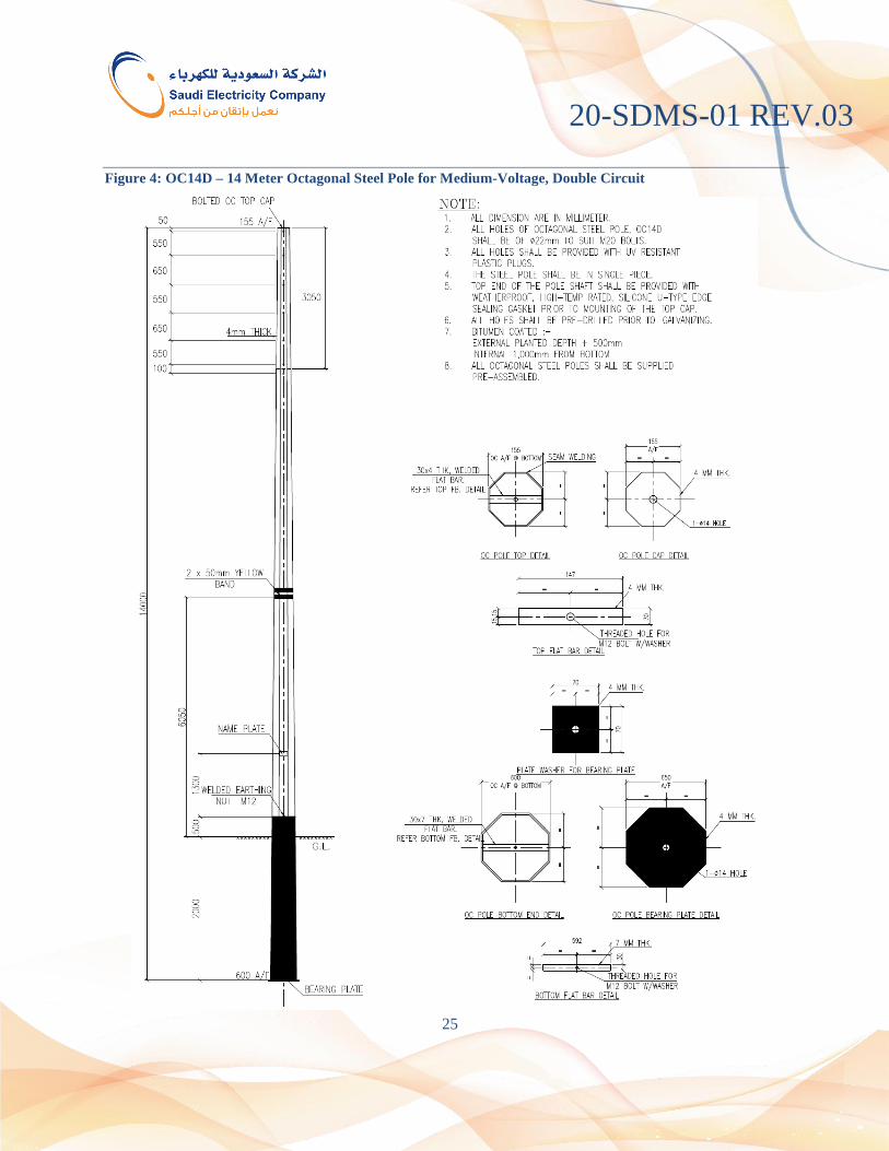
Figure 4: OC14D – 14 Meter Octagonal Steel Pole for Medium-Voltage, Double Circuit

20-SDMS-01 REV.03
26
Figure 5: OC15S/D – 15 Meter Octagonal Steel Pole for Medium-Voltage, Single or Double Circuit

20-SDMS-01 REV.03
27
Figure 6: OC10SFS – 10 Meter Octagonal Steel Pole for Low-Voltage, Self-Support

20-SDMS-01 REV.03
28
Figure 7: OC13SFS – 13 Meter Octagonal Steel Pole for Medium-Voltage, Self-Support Single-Circuit

20-SDMS-01 REV.03
29
Figure 8: OC14SFS – 14 Meter Octagonal Steel Pole for Medium-Voltage, Self-Support Single-Circuit

20-SDMS-01 REV.03
30
Figure 9: OC15SFS – 15 Meter Octagonal Steel Pole for Medium-Voltage, Self-Support Single-Circuit