2007 academic challenge - university of illinois at · pdf file ·...
TRANSCRIPT

2007 Academic Challenge
ENGINEERING GRAPHICS TEST - REGIONAL
This Test Consists of 50 Questions
Engineering Graphics Test Production Team
Ryan Brown, Illinois State University – Author/Team Coordinator Kevin Devine, Illinois State University – Author
Jacob Borgerson, University of Illinois at Urbana - Champaign – Reviewer Don Wayman, WYSE – Coordinator of Test Production
GENERAL DIRECTIONS Please read the following instructions carefully. This is a timed test; any instructions from the test supervisor should be followed promptly. The test supervisor will give instructions for filling in any necessary information on the answer sheet. Most Academic Challenge sites will ask you to indicate your answer to each question by marking an oval that corresponds to the correct answer for that question. Only one oval should be marked to answer each question. Multiple ovals will automatically be graded as an incorrect answer. Be sure ovals are marked as . Not as , , etc. , If you wish to change an answer, erase your first mark completely before marking your new choice. You are advised to use your time effectively and to work as rapidly as you can without losing accuracy. Do not waste your time on questions that seem too difficult for you. Go on to the other questions, and then come back to the difficult ones later if time remains.
*** TIME: 40 MINUTES ***
DO NOT OPEN TEST BOOKLET UNTIL YOU ARE TOLD TO DO SO!
© 2007 Worldwide Youth in Science and Engineering
“WYSE”, “Worldwide Youth in Science and Engineering” and the “WYSE Design” are service marks of and this work is Copyright © 2007 Board of Trustees of the University of Illinois at Urbana - Champaign.
All rights reserved.

WYSE – Academic Challenge Engineering Graphics Test (Regional) – 2007
1. Considering both architectural and
engineering systems of paper, which of the following is NOT a standard paper size?
A. 8.5” x 11”
B. 18” x 24”
C. 22” x 34”
D. 17” x 22”
E. 11” x 18”
2. If a floor plan drawing of a new 14’ x 25’ machine shop is to be placed on C-size paper, which scale would you recommend for the largest size possible?
A. 1/8” = 1’-0”
B. 1/4” = 1’-0”
C. 1/2” = 1’-0”
D. 1” = 1’-0”
E. 1” = 10’
3. A red and white barber pole and candy peppermint stick are examples of a geometric construction known as a(n) _____________.
A. helix
B. spiral
C. cycloid
D. involute
E. parabola
4. Considering ALL surfaces on the object illustrated below, how many of the surfaces are perpendicular to the profile plane, thus appearing as lines in the right side view?
A. 3
B. 4
C. 5
D. 6
E. 7
5. If two identical size squares are drawn in such a way as to overlap, and then the four corners of one are connected to the respective corners of the other, the result illustrates the principles of ______________ projection.
A. oblique
B. isometric
C. orthographic
D. dimetric
E. trimetric
2007 Regional

6. If the front view of this drawing is converted into a full section view, how many bounded areas will the new sectional view have that need section lines (hatching)?
A. 1
B. 2
C. 3
D. 4
E. 5
7. To show the true size and shape of the circular feature of this part:
A. Create a right side view rotated
90°
B. Project an auxiliary view off the front view
C. Create a partial top view
D. Create a secondary auxiliary view
E. Project an auxiliary view off the top view
Engineering Graphics – 2
8. The ASME organization standardizes practices for engineering graphics. The “S” stands for:
A. Standard
B. Society
C. Skill
D. System
E. Student
9. A CAD system has a relative polar input syntax of “=distance<direction”. For example, to draw a vertical line up the page 2 inches, enter “=2<90”. What geometric shape is described by =1<120; =1<240; =1<300; =1<60?
A. square
B. stair steps
C. hour-glass
D. rectangle
E. diamond
10. A rounded exterior edge of an object is termed:
A. fillet
B. runout
C. round
D. chamfer
E. break
2007 Regional

2007 Regional
11. Which of the holes in the illustration
below is a threaded hole?
A. A
B. B
C. C
D. D
E. E
12. In a local note, the symbol noted below is associated with a(n):
A. through hole
B. depth value
C. runout tolerance
D. finished surface
E. spotface diameter
13. The two parts illustrated below are designed to always have a clearance fit. Each part has a tolerance of size as indicated. What is the “tightest” fit of these two parts?
A. .0011”
B. .0021”
C. .0024”
D. .0044”
E. .0059”
Engineering Graphics – 3
14. Identify the number of degrees when these two standard drawing triangles are put together as shown.
A. 60°
B. 95°
C. 105°
D. 120°
E. 135°
15. Identify the scale pictured below:
A. Mechanical Engineer’s Scale
B. Metric Scale
C. Architect’s Scale
D. Triangular Ruler
E. Civil Engineer’s Scale
16. A graphic design features an octagon inscribed inside of a circle. How many points of tangency are there between the octagon and the circle?
A. 0
B. 2
C. 4
D. 6
E. 8

2007 Regional
17. At minimum, to create a correct multiview drawing, how many visible and hidden line segments will it take to complete the “missing line problem” illustrated below?
A. 4
B. 5
C. 6
D. 7
E. 8
18. What caption is best for the illustration below?
A. How to create oblique pictorial
circles
B. Circles in 2-point perspective
C. Creating an ogee curve
D. Creating a four-center ellipse
E. 5-point ellipse construction
Engineering Graphics – 4
19. Select the full section that is correctly drawn:
A. A
B. B
C. C
D. D
E. E
20. The ASME standard symbol for diameter is:
21. Which of the following components is
most likely required for all CAD stations?
A. 3.5” floppy disk drive
B. Joystick input device
C. CPU mother board
D. Roll feed plotter
E. 12” square digitizing tablet

2007 Regional
22. A _______________ mark can be added to a drawing to indicate a surface must be machined smooth.
A. slope
B. check
C. tolerance
D. finish
E. pound
23. The words SQUARE, SLOTTED, FILLISTER, & HEX SOCKET all refer to a type of:
A. Knurl
B. Fastener head
C. Spring
D. Key
E. Gear
24. What is the minimum number of dimensions that should be added to these views to completely describe the object?
A. 5
B. 6
C. 8
D. 9
E. 11
Engineering Graphics – 5
25. Identify the drafting equipment pictured below:
A. Dividers
B. Beam compass
C. Ruling pen
D. Bow compass
E. Leroy device
26. Given parallel lines 1 & 2, and parallel lines 3 & 4 not perpendicular to 1 & 2, which of the formula below is TRUE?
A. A + B + C + D = 180°
B. E + F + G + H = 360°
C. A + G = 180°
D. E + G = 90°
E. A + E + G + C = 360°
2007 Regional
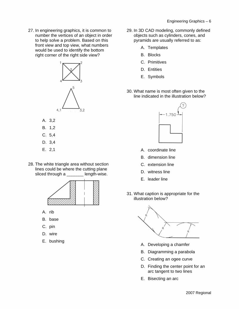
27. In engineering graphics, it is common to number the vertices of an object in order to help solve a problem. Based on this front view and top view, what numbers would be used to identify the bottom right corner of the right side view?
A. 3,2
B. 1,2
C. 5,4
D. 3,4
E. 2,1
28. The white triangle area without section lines could be where the cutting plane sliced through a _______ length-wise.
A. rib
B. base
C. pin
D. wire
E. bushing
Engineering Graphics – 6
29. In 3D CAD modeling, commonly defined objects such as cylinders, cones, and pyramids are usually referred to as:
A. Templates
B. Blocks
C. Primitives
D. Entities
E. Symbols
30. What name is most often given to the line indicated in the illustration below?
A. coordinate line
B. dimension line
C. extension line
D. witness line
E. leader line
31. What caption is appropriate for the illustration below?
A. Developing a chamfer
B. Diagramming a parabola
C. Creating an ogee curve
D. Finding the center point for an arc tangent to two lines
E. Bisecting an arc

2007 Regional
Engineering Graphics – 7
32. The definition of a normal surface is one that is parallel to a principal plane of projection (frontal, horizontal, profile). For the object illustrated below, counting ALL surfaces, how many normal surfaces are there?
34. With respect to dimensioning this shape, which of the following is a TRUE statement?
A. 10 dimensions are required for
this shape, including A to E and K to F
A. 7
B. 8
C. 9 B. A dimension from A to E, if used, must be placed below the view D. 10
C. Four baseline dimensions are required from left to right, and they are A to B, A to C, A to D, and A to E
E. 11
33. On most CAD systems, the polar coordinate system uses 0° as the horizontal direction, drawing directly to the right (3 o’clock). What two values could be specified to draw a line that heads toward 7 o’clock, 10° counter-clockwise of straight down?
D. A dimension from K to J, if used, must be placed on the left side of the view
E. 8 dimensions are required for this shape, but the selection is optional and dependent on the function and relationship of the features.
A. 260 or -100
B. 100 or -250
C. -180 or 80
D. 190 or -10
E. -80 or 280

Engineering Graphics – 8
2007 Regional
Engineering Graphics – 9
2007 Regional

Engineering Graphics – 10
2007 Regional

Engineering Graphics – 11
2007 Regional