20070102 sacma collision avoidance presentation
TRANSCRIPT

Collision Avoidance System Presentation
to SACMA Regional Meeting11 January 2006
Presentation by Johann du PlessisManager Engineering, Xstrata Coal South Africa

A “Business Case” for an underground Collision Avoidance System
We all have:• Training for personnel• Codes of Practice• Standard Procedures• Supervisory structures
Aimed at preventing injury to people

A “Business Case” for an underground Collision Avoidance System
In addition Xstrata Coal SA has • Cardinal Rules• A 3 Meter rule• VVL• Behaviorally Based Safety
The intent of all is to ensure our personnel and visitors go home UNHARMED

A “Business Case” for an underground Collision Avoidance System
So why, in spite of all the ingenious management systems, do people still get killed or seriously injured?

A “Business Case” for an underground Collision Avoidance System
Our systems rely on human behavior
Human behavior is fallible
Unfortunately, in this case, when the behavior patterns fail, the potential for fatality is huge

A “Business Case” for an underground Collision Avoidance System
The Collision Avoidance System:• Does not replace any of the existing “Soft Barriers”• Strives to provide an automated “Hard Barrier” between people and
machines,• Does not rely on human behavior

Take a machine and add a radio transmitter and receiver to it
What is a Collision Avoidance System and how does it function ?

Fit a radio transmitter and receiver to the cap lamps worn by personnel
What is a Collision Avoidance System and how does it function ?

The machine transmits a radio signal which is received by the cap lamp activating a flashing light or buzzer warning the person of the presence of a machine
What is a Collision Avoidance System and how does it function ?

The cap lamp transmits a radio signal which is received by the machine activating a flashing light or buzzer warning the machine operator of the presence of a pedestrian
What is a Collision Avoidance System and how does it function ?

• Both the pedestrian and the machine operator are now aware of the other and can take evasive action.
• Quite simple and ingenious.• There are numerous systems, from different suppliers, in operation
around the world
What is a Collision Avoidance System and how does it function ?

Vehicle Transmitter Personnel Receiver and transmitter
What is a Collision Avoidance System and how does it function ?

Vehicle Count
Personnel Count
Buzzer ON/OFF
Key Switch
Buzzer Alarm
High bright Flashing Indicator
PowerIndicator
Syst em OK
Indicator
Tag Detected
Antenna Connection
12v to 24V Power
DetailDisplay
Machine Mounted unit
What is a Collision Avoidance System and how does it function ?

Collahausi Mine Chile
Xstrata Alloys Rustenburg
PT Freeport Indonesia
Pasminco Broken Hill
Some example of Collision Avoidance Systems in operation

• The radio signal transmits omni-directional• The signal maintains near constant strength over a 40 to 100 meters
distance
Is it really that simple?

Add four more machines in a confined environment like a production section
Is it really that simple?

Add some more people
Is it really that simple?

The signals get so cluttered and confusing that nobody reacts to any signal and we are back to where we started
Is it really that simple?

A production section contains numerous machines and people in a relatively small area
• Continuous Miner• Shuttle Car• Roof Bolter• Feeder Breaker• LHD• Person
What is the solution?
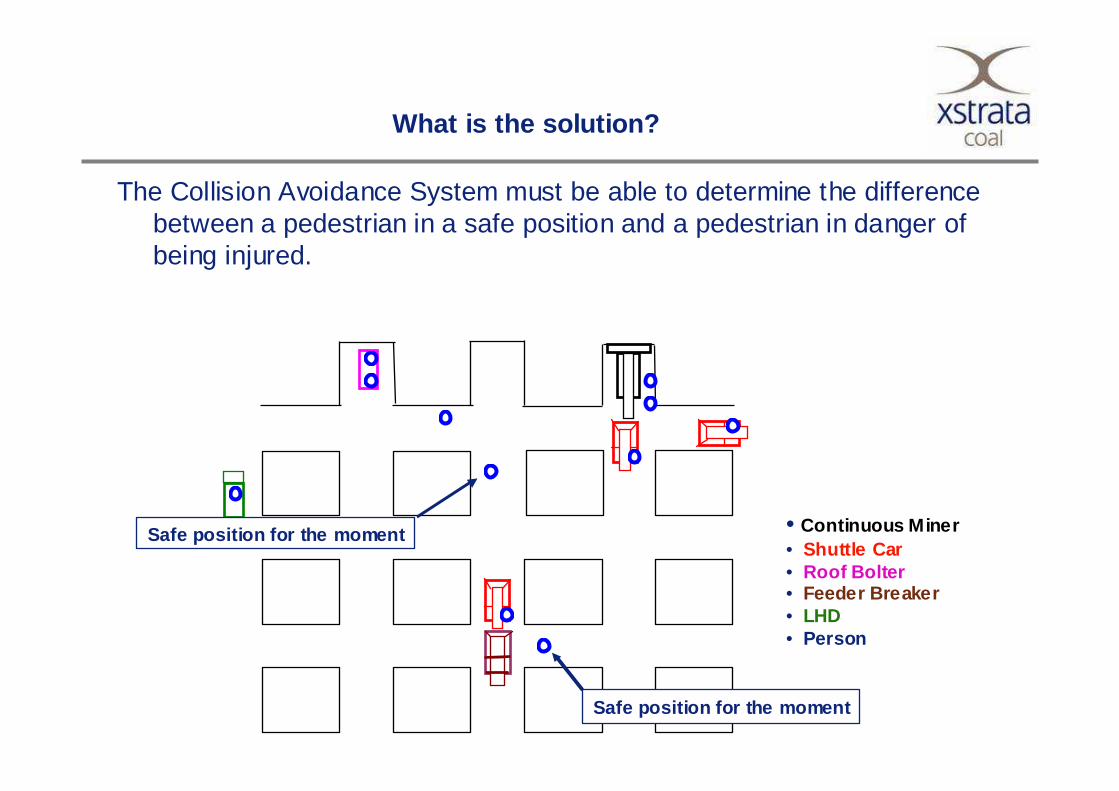
The Collision Avoidance System must be able to determine the difference between a pedestrian in a safe position and a pedestrian in danger of being injured.
• Continuous Miner• Shuttle Car• Roof Bolter• Feeder Breaker• LHD• Person
Safe position for the moment
Safe position for the moment
What is the solution?
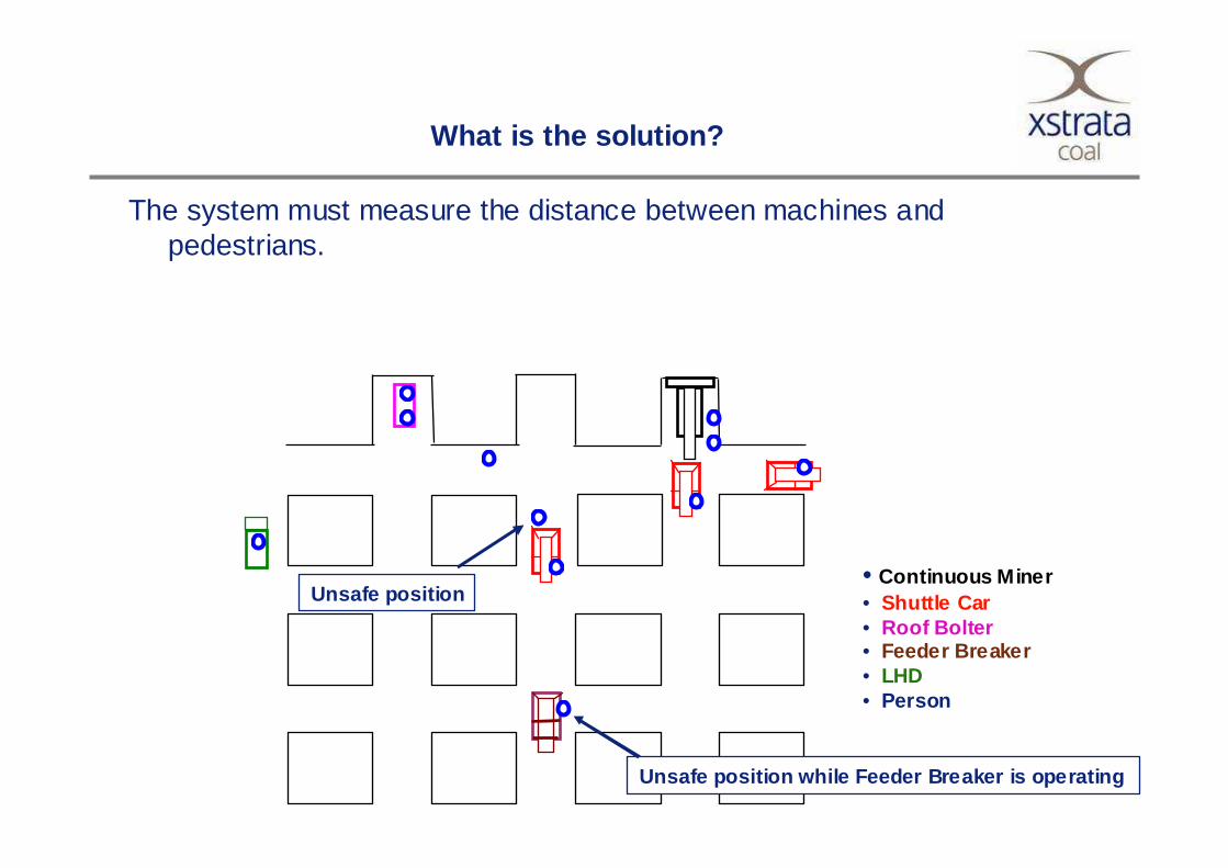
The system must measure the distance between machines and pedestrians.
• Continuous Miner• Shuttle Car• Roof Bolter• Feeder Breaker• LHD• Person
Unsafe position while Feeder Breaker is operating
Unsafe position
What is the solution?

The system must measure the distance between machines.
• Continuous Miner• Shuttle Car• Roof Bolter• Feeder Breaker• LHD• Person
Unsafe situationShuttle Car is approaching Roof BolterRoof Bolter is on Shuttle Car driver blind side
What is the solution?

• The system must determine the distance between the individual and the machine and create a “Halo” around the machine
• The Final Barrier around the machine defines the unsafe area
Less than 3 meters = Unsafe
More than 3 Meters = Safe
3 Meter
3 Meter
3 Meter
3 Meter
Unsafe area
Final Barrier
Distance measurement

• The Final Barrier is a “Hard Barrier”• At the Final Barrier we stop relying on human behavior• Intrusion into the Final Barrier activates an automatic intervention in the
machine control system– Shuttle Car - The brakes are engaged– Continuous Miner – Cutter head and Tramming is disengaged– Feeder Breaker – The emergency stop is activated– LHD – The brakes are activated
Unsafe area
Final Barrier
“Hard Barrier”

The system operational logic defines under which circumstances a Final Barrier breach is allowed
The system must differentiate between: The Shuttle Car driver approaching the Feeder Breaker on his Schuttle Car on the right
The Schuttle Car diver approaching the Feeder Breaker on foot on the left
The system must differentiate between: The Shuttle Car driver approaching the CM operator at his CM on the right
The Schuttle Car diver approaching the CM operator alone on the left
The system must differentiate between: The Artisan doing fault finding on the right
The Artisan walking through the section on the left
System Logic

Two systems are in the process of development for the coal mining industry:
• Becker Mining trial at the Xstrata Coal South Africa Group Training Center at Tavistock Colliery
• Mine Site Technologies development with the support of ACARP, Xstrata Coal and Centennial Coal.
System developments in progress

Technical Challenges:• Radio Frequency propagation in an underground environment is affected
by antenna positioning, surrounding steel infrastructure, type of rock strata and tunnel dimensions.
• This results in a variance in the distance in which the tag is detected. Typically between 5-30 metres. (far field)
• To this end RF tags in isolation are not suitable for short range detection. (near field)
System developments in progress

Technical Solution:• By using ultrasonic transmitters and receivers a quick and accurate
measurement can be achieved.• Ultrasonic transducers have been successfully deployed in modern
vehicles (PDC) Park Distance Control.• The PDC system however does not discriminate between a sidewall,
vehicle and person.• By encoding and decoding the Ultrasonic pulses the system can identify
the difference between Personnel, Vehicles and inanimate objects.• Distance measurement is achieved by the processing the time difference
between when the tag RF signal versus the tag ultrasonic signal is received.
System developments in progress

System Principle:• The Tag and ultrasonic ID is transmitted simultaneously. • Distance measurement is accomplished by measuring the difference in
time between the reception of the Ultrasonic ID and the Radio ID. .
Ultrasonic Transmitter
RF Tag Transmitter
Ultrasonic Receiver
RF Tag Receiver
T1 = Time for Ultrasonic Code to be received (dependant on distance)
T2 = Time for RF Tag be received (Speed of Light = Fixed)
System developments in progress

The system will discriminate between near and far presence of pedestrians and machines.
Far Field 5-30m
Near Field 0-5m
System developments in progress

As the system is dependant on “line-of site”, antennas /ultrasonic receivers will be placed on the 4 corners of machines thus ensuring complete coverage.
Multiple antennas (DPOD’S) are connected to the CAS Controller via RS485 serial connection. The CAS displays the tags within the danger zones.
RS 485 Bus
CAS Controller
Personnel & Ultrasonic Transmit ter
DPOD Recei ver 1
Personnel & Ultrasonic Transmit ter
Personnel & Ultrasonic Transmit terPersonnel & Ultrasonic Transmit ter
DPOD Recei ver 2
DPOD Recei ver 3DPOD Recei ver 4
System developments in progress

System developments in progress

Tavistock trial progress• An LHD was fitted with the CAS 400• 20 Cap Lamps were equipped with the RF tags and ultrasonic transmitters • The ultrasonic RF combination has demonstrated the capability of measuring
distance with extreme accuracy• To date the system has not demonstrated the ability to create an effective Final
Barrier around the machine• The trial is continuing• Definitive results are not expected before May 2007
System developments in progress

Background
Mine Site Technologies with the support of ACARP, Xstrata Coal and Centennial Coal is currently undertaking a Project to develop a “Proximity Detection” system aimed at developing technology to help avoid people/vehicle and vehicle/vehicle collisions in a mining environment.
System developments in progress

The technology under development basically consists of:
• People and vehicles carry active tags with a range of more than 50m.
• A Tag Reader is fitted on the vehicle. When the receiver on the vehicle receives a tag signal it gives a medium-level alarm to indicate that a person/vehicle is around.
• A magnetic field antenna (a so called “Exciter”) is fitted on the vehicle. This antenna transmits its own ID using a magnetic field, the size of this magnetic field can be adjusted relatively accurately.
• When a tag on a person/vehicle receives this magnetic signal it sends out an alarm message to indicate that it is within dangerous range of a magnetic antenna.
• When the receiver on the vehicle receives this alarm tag signal it gives a high-level alarm.
System developments in progress

Receiver
Exciter
Tag
System developments in progress

Two types of active tags are currently being used:
• TRACKER UHF Tags have:A 433MHz transmitter;These Tags are already in use at mines that have installed theTRACKER Tagging System, and are already proven in use andapproved Intrinsically Safe in Australia, USA and China.
TRACKER UHF TagAlready in use at mines and IS
Approved
System developments in progress

Two types of active tags are currently being used:
802.11b Tags have:A 2.4 GHz transmitter, and also includea magnetic receiver capable of receivingthe Exciter’s signal;
The version of these Tags that fit into theICCL (Integrated Communications CapLamp) are currently going through approvalfor coal mine use in the USA and Australia.
ICCL – a cap Lamp that can include UHF or 802.11b RFID Tag
System developments in progress

An Exciter is also being investigated to determine its use in providing a second inner zone warning:
• “Exciter” units from Mine Site produce a constant low-frequency (125kHz)magnetic field around them.
• The size of this field can be adjusted in increments of 50cm via a TCP/IPinterface. The current units have a range limit of 6m.
• One of the on-going areas of development is to increase this range to 10 or20m to make it viable as an “inner, higher danger zone”.
System developments in progress

TRACKER and 802.11 (WLAN) tests
The underground survey results confirmed very good signal coverage up to 80 m from vehicle mounted Reader.
Straight down the roadways the signal did not fall below the threshold, there is continuous coverage.
Though the signal decays quickly around corners there is still limited coverage.
System developments in progress

Reception around corners (both TRACKER and WLAN tags)It is essential that the Proximity detection system can detect tags that are around a corner, so that the system is not “surprised” by a tag suddenly coming into radio view around a corner.
System developments in progress
Tag Test Conclusion
Both the TRACKER and WLAN Tags have reliable reception and sufficient range to be used in this application.
Further definition of guaranteed read range will be required to define system specifications and confirm they meet application expectations.
System developments in progress

Exciter Range and Stability TestsMinimum/Maximum Range: Exciter mounted on top of vehicle
System developments in progress

Minimum/Maximum Range: Underground test, Exciter mounted on top of vehicle
System developments in progress

Exciter Test Conclusion
A decision needs to be made whether the Exciter’s range is accurate enough for Proximity detection.
The Exciter’s range is unlikely to be sufficient, it needs to be increased to at least 10 - 20m to provide the level of protection required for the “inner” zone.
These tests have to be repeated after increasing the Exciter’s range.
System developments in progress

Project Time Table
The next series of trials is planned for early 2007.
These will test the pre-production prototype, which will give design confirmation and form the basis for the final commercialisation phase.
It is anticipated production system will be released in early 2008.
System developments in progress

There is no proven Collision Avoidance System suitable for use in underground coal mines available at present.
Indications are good that the first commercial systems which will provide a barrier, not reliant on human behavior, will be available in 2008.
Conclusion