2009 11 17 sr 5510.09 tr 1043 en november 2009vendor.parker.com/852568c80043fa7a... · test...
TRANSCRIPT

TEST SERVICES
AN EVALUATION OF THE SHIELDING EFFECTIVENESS OF
PARKER CHOMERICS CHO‐SEAL EMI SHIELDING ELASTOMERS PER CHO‐TP09
Date: November 17, 2009 Test Report Number: SR 5510.09 / TR 1043 EN November 2009
IN ACCORDANCE WITH CHO‐TP09 Prepared For: PARKER CHOMERICS
77 DRAGON COURT WOBURN, MA 01801
Prepared By: PARKER CHOMERICS TEST SERVICES 77 DRAGON COURT WOBURN, MASSACHUSETTS 01801 WARNING – USER RESPONSIBILITY FAILURE OR IMPROPER SELECTION OR IMPROPER USE OF THE PRODUCTS DESCRIBED HEREIN OR RELATED ITEMS CAN CAUSE DEATH, PERSONAL INJURY AND PROPERTY DAMAGE. This document and other information from Parker‐Hannifin Corporation, its subsidiaries and authorized distributors provide product or system options for further investigation by users having technical expertise. The user, through its own analysis and testing, is solely responsible for making the final selection of the system and components and assuring that all performance, endurance, maintenance, safety and warning requirements of the application are met. The user must analyze all aspects of the application, follow applicable industry standards, and follow the information concerning the product in the current product catalog and in any other materials provided from Parker or its subsidiaries or authorized distributors. To the extent that Parker or its subsidiaries or authorized distributors provide component or system options based upon data or specifications provided by the user, the user is responsible for determining that such data and specifications are suitable and sufficient for all applications and reasonably foreseeable uses of the components or systems.

TEST SERVICES
Document #: SR 5510.09 / TR 1043 EN November 2009 Date: November 17, 2009
Page 2 of 35
TABLE OF CONTENTS 1 GENERAL 4 1.1 PURPOSE 4 1.2 ADMINISTRATIVE INFORMATION 4 1.2.1 TEST FACILITY 4 1.2.2 EQUIPMENT CALIBRATION 5 1.2.3 TEST PERSONNEL 5
2 TEST SET‐UP 5 2.1 TEST SITE DESCRIPTION 5 2.2 TEST PLATE SETS 6 2.3 FIXTURE HARDWARE 10 2.4 TEST SAMPLES 11
3 TEST PLATE SET ASSEMBLY 12 3.1 EQUIPMENT LIST 12 3.2 ASSEMBLY PROCEDURE 12
4 ENVIRONMENTAL EXPOSURE 14 4.1 EQUIPMENT LIST 14 4.2 EXPOSURE CONDITIONS 14 4.3 OVERVIEW OF TEST PLATE SETS: SUBSTRATE VS. EXPOSURE CONDITIONS 14
5 TESTS PERFORMED ‐ ELECTRIC AND PLANE WAVE SHIELDING EFFECTIVENESS (SE) 15 5.1 EQUIPMENT LIST 15 5.2 TEST METHOD 15 5.3 EXPERIMENTAL RESULTS 18 5.4 CONCLUSIONS 32
6 PHOTOGRAPHIC DOCUMENTATION 33

TEST SERVICES
Document #: SR 5510.09 / TR 1043 EN November 2009 Date: November 17, 2009
Page 3 of 35
List of Tables TABLE 1 : EQUIPMENT LIST FOR CHO‐TP09 TEST FIXTURE ASSEMBLY 12 TABLE 2 : CHO‐TP09 TEST PLATE SET HARDWARE – ONE COMPLETE SET 12 TABLE 3 : ENVIRONMENTAL AGING EQUIPMENT 14 TABLE 4 : ENVIRONMENTAL AGING EXPOSURE CONDITIONS 14 TABLE 5 : SUMMARY OF TEST PLATE SET FLANGE TREATMENTS EVALUATED PER ENVIRONMENTAL EXPOSURE 14 TABLE 6 : ELECTRIC AND PLANE WAVE SHIELDING EFFECTIVENESS TEST EQUIPMENT 15
List of Figures FIGURE 1 : SCHEMATIC OF CHOMERICS "SHIELDING EFFECTIVENESS" TEST CHAMBER 6 FIGURE 2 : CHO‐TP09 TEST FRAME 7 FIGURE 3 : CHO‐TP09 TEST COVER PLATE 8 FIGURE 4 : MAIN ADAPTER PLATE FOR MOUNTING TEST PLATE SETS TO WALL OF SHIELDED ENCLOSURE 9 FIGURE 5 : EXAMPLE OF CHO‐TP09 GASKET TEST WINDOW SHIM 10 FIGURE 6 : DRAWING OF SOLID “D” PROFILE 11 FIGURE 7 : EXAMPLE OF CHO‐TP09 TEST PLATE SET 13 FIGURE 8 : CHO‐TP09 SHIELDING EFFECTIVENESS OPEN REFERENCE TEST SET‐UP 16 FIGURE 9 : CHO‐TP09 SHIELDING EFFECTIVENESS FINAL MEASUREMENT TEST SET‐UP 17 FIGURE 10 : EXPANDED CROSS SECTIONAL VIEW OF CHO‐TP09 TEST PLATE SET‐UP 17 FIGURE 11 : SHIELDING EFFECTIVENESS: NI/AL CHO‐SEAL ‐ INITIAL / DRY HEAT / HUMIDITY / SALT FOG 22 FIGURE 12 : SHIELDING EFFECTIVENESS: AG/AL CHO‐SEAL ‐ INITIAL / DRY HEAT / HUMIDITY / SALT FOG 27 FIGURE 13 : SHIELDING EFFECTIVENESS COMPARISON: NI/AL VS. AG/AL ‐ INITIAL BASELINE 28 FIGURE 14 : SHIELDING EFFECTIVENESS COMPARISON: NI/AL VS. AG/AL ‐ 2,000 HOURS @ 125°C DRY HEAT 29 FIGURE 15 : SHIELDING EFFECTIVENESS COMPARISON: NI/AL VS. AG/AL ‐ 1,000 HOURS @ 85°C & 85% RH 30 FIGURE 16 : SHIELDING EFFECTIVENESS COMPARISON: NI/AL VS. AG/AL ‐ 500 HOURS @ SALT FOG 31
List of Data Sheets DATA SHEET 1 : NI/AL CHO‐SEAL ‐ INITIAL BASELINE SE 18 DATA SHEET 2 : NI/AL CHO‐SEAL ‐ SE AFTER 2,000 HOURS @ 125°C DRY HEAT 19 DATA SHEET 3 : NI/AL CHO‐SEAL ‐ SE AFTER 1,000 HOURS @ 85°C & 85%RH 20 DATA SHEET 4 : NI/AL CHO‐SEAL ‐ SE AFTER 500 HRS NEUTRAL (ASTM B117) SALT FOG 21 DATA SHEET 5 : AG/AL CHO‐SEAL ‐ INITIAL BASELINE SE 23 DATA SHEET 6 : AG/AL CHO‐SEAL ‐ SE AFTER 2,000 HOURS @ 125°C DRY HEAT 24 DATA SHEET 7 : AG/AL CHO‐SEAL ‐ SE AFTER 1,000 HOURS @ 85°C & 85%RH 25 DATA SHEET 8 : AG/AL CHO‐SEAL ‐ SE AFTER 500 HRS NEUTRAL (ASTM B117) SALT FOG 26

TEST SERVICES
Document #: SR 5510.09 / TR 1043 EN November 2009 Date: November 17, 2009
Page 4 of 35
1 General 1.1 Purpose
Conductive EMI gaskets are used to seal apertures in electronic enclosures against leakage of electromagnetic radiation. Metal‐filled homogeneously conductive elastomers are one type of EMI gaskets used for this purpose. Conductive elastomers consist of small metal particles, typically in the range of 30 to 150 microns, dispersed within an elastomer binder system. Typical metal fillers include silver, silver plated materials (e.g., copper, glass, aluminum, nickel), nickel, nickel plated materials (e.g., aluminum, graphite and glass), and carbon. Examples of typical binders include silicone and fluorosilicone based resin systems. The purpose of this document is to report the shielding effectiveness of Parker Chomerics Ni/Al and Ag/Al filled CHO‐SEAL materials on chromate treated surfaces before and after environmental exposure per Chomerics Test Procedure CHO‐TP09. Although this evaluation does not replicate the mechanical and/or electrical performance of a gasket in an actual electronic enclosure, it does allow for comparative evaluations between gasket materials using a standardized setup and test procedure. The data obtained from these tests may or may not be equivalent to a gasket performance when installed in an actual enclosure (application). Variables such as metal surface treatment, gasket deflection, flange configuration, fastener spacing, as well as the source, amplitude, and frequency of electromagnetic fields all play a part in the shielding effectiveness of a gasket system installed in an electronic enclosure. Care should be taken in applying the absolute values obtained from these tests to other gasket/ flange geometries or enclosure designs. All testing was performed by Chomerics Test Services of Woburn, Massachusetts over the period of four months from July 2009 to November 2009.
1.2 Administrative Information 1.2.1 Test Facility
The Parker Chomerics test facility operates under the current revision of Chomerics Test Services Quality Assurance (QA) Manual Document Number QA002. The QA Manual has been constructed to reflect a quality program in accordance with the requirements of the National Institute of Standards and Technology (NIST), ISO 9002, ISO Guide 25, NIST Handbook 150, EN 45001, MIL‐I‐45208A, MIL‐STD‐461D, 462D and Chomerics Test Services Quality Assurance Program (QAP). The QA Manual outlines and describes the procedures for establishing and maintaining the quality of analysis, research, inspection, and testing within Chomerics Test Service (CTS).
TEST SERVICES
Document #: SR 5510.09 / TR 1043 EN November 2009 Date: November 17, 2009
Page 5 of 35
This test report does not represent an endorsement by the U.S. Government. The results and/or conclusions within this test report refer and/or apply only to the unit(s) tested as defined by this report. Measurements performed for this test are traceable to the National Institute of Standards and Technology (NIST) based on the fact that all test equipment used for the measurements were previously calibrated using standards traceable to NIST. The system amplitude accuracy for the measurements made during the radiated emission tests was ±3dB. Chomerics Test Services measurement uncertainty calculations are available for review upon request.
1.2.2 Equipment Calibration The calibration of Chomerics test facility equipment is controlled under the current revision of Chomerics Laboratory Test Equipment Calibration Manual Document Number QA001. The test equipment used throughout this test sequence conforms to laboratory calibration standards, ANSI/NCSL Z540‐1, traceable to the National Institute of Standards and Technology (NIST). The date of the last calibration is listed in each test section for the applicable equipment. We certify that the test equipment used to perform this test was in calibration at the time of the test and are calibrated per ANSI/NCSL Z540‐1 at least once per year.
1.2.3 Test Personnel
The test personnel performing or supervising the tests are accredited by the National Association of Radio and Telecommunications Engineers, Inc. (NARTE) as Certified Electromagnetic Compatibility Engineers (N.C.E.) and Technicians (N.C.T.).
2 Test Set‐Up 2.1 Test Site Description
All electric and plane wave shielding effectiveness measurements were performed at the Chomerics "Shielding Effectiveness" Test Chamber located in the Seeger Building at Parker Chomerics, 84 Dragon Court, Woburn, Massachusetts (see Figure 1). The shielded enclosure was manufactured by Sprague Shielding Corporation. Attenuation tests have demonstrated that the enclosure meets the attenuation requirements of IEEE‐STD‐299.
TEST SERVICES
Document #: SR 5510.09 / TR 1043 EN November 2009 Date: November 17, 2009
Page 6 of 35
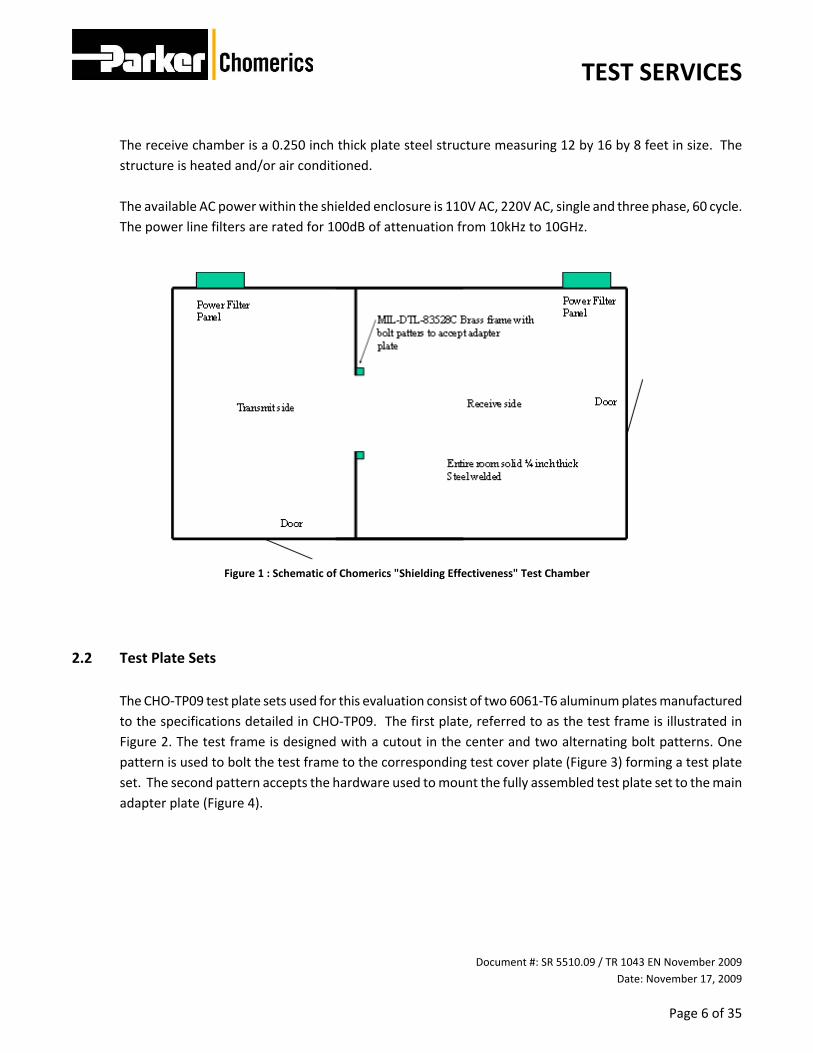
The receive chamber is a 0.250 inch thick plate steel structure measuring 12 by 16 by 8 feet in size. The structure is heated and/or air conditioned. The available AC power within the shielded enclosure is 110V AC, 220V AC, single and three phase, 60 cycle. The power line filters are rated for 100dB of attenuation from 10kHz to 10GHz.
Figure 1 : Schematic of Chomerics "Shielding Effectiveness" Test Chamber
2.2 Test Plate Sets The CHO‐TP09 test plate sets used for this evaluation consist of two 6061‐T6 aluminum plates manufactured to the specifications detailed in CHO‐TP09. The first plate, referred to as the test frame is illustrated in Figure 2. The test frame is designed with a cutout in the center and two alternating bolt patterns. One pattern is used to bolt the test frame to the corresponding test cover plate (Figure 3) forming a test plate set. The second pattern accepts the hardware used to mount the fully assembled test plate set to the main adapter plate (Figure 4).

TEST SERVICES
Document #: SR 5510.09 / TR 1043 EN November 2009 Date: November 17, 2009
Page 7 of 35
Figure 2 : CHO‐TP09 Test Frame
The test cover plate (Figure 3) is also made from 6061‐T6 aluminum and has the identical bolt hole configuration as the test frame described above.

TEST SERVICES
Document #: SR 5510.09 / TR 1043 EN November 2009 Date: November 17, 2009
Page 8 of 35
Figure 3 : CHO‐TP09 Test Cover Plate
A 0.500 inch thick 6061‐T6 aluminum main adapter plate illustrated in Figure 4 was used to mount the test plate sets to the shielded room wall. The outer bolt pattern detailed in Figures 4 was used to mate the adapter plate to the wall of the shielded room. The inner bolt pattern accepts the Test Plate set.

TEST SERVICES
Document #: SR 5510.09 / TR 1043 EN November 2009 Date: November 17, 2009
Page 9 of 35
Figure 4 : Main Adapter Plate for Mounting Test Plate Sets to Wall of Shielded Enclosure
The following chromate conversion coating flange treatments were evaluated:
• MIL‐C‐5541, Class 3 Trivalent Chromate
• MIL‐C‐5541, Class 3 Hexavalent Chromate

TEST SERVICES
Document #: SR 5510.09 / TR 1043 EN November 2009 Date: November 17, 2009
Page 10 of 35
2.3 Fixture Hardware In addition to the test plates, non‐conductive lexan shims were used as compression stops to target a nominal gasket deflection of 13.1%. The shims, illustrated in Figure 5, are designed to fit the bolt patter on the plate sets and prevent uneven deflection in regions adjacent to the bolts. Four shims were used per Test Plate set, one shim per side.
Figure 5 : Example of CHO‐TP09 Gasket Test Window Shim
Black oxide alloy steel socket head cap screws were used to bolt the Test Plate Covers and Frames together and to bolt the plate sets to the shielded room wall.

TEST SERVICES
Document #: SR 5510.09 / TR 1043 EN November 2009 Date: November 17, 2009
Page 11 of 35
2.4 Test Samples The Cho‐Seal gasket test samples were compounded and manufactured by trained operators per the approved manufacturing process instructions. The test sample profile consisted of a Solid “D” cross‐section with nominal measurements of 0.175 inch in height by 0.178 inch in width as specified by CHO‐TP09 (see Figure 6). For this evaluation, the Ni/Al filled elastomer is represented by the molded and extruded versions of CHO‐SEAL 6502 and CHO‐SEAL 6503, while the Ag/Al filled counterpart corresponds to the molded and extruded versions of CHO‐SEAL 1298.
The Test Plate gasket configuration varied depending on the grade of the material. Extrusion grade elastomer gaskets consisted of a single part approximately 56.0 inches in length with the ends cut at complimentary 45 degree angles. Molding grade elastomer gaskets consisted of two 28.0 inch long parts with the ends cut at complimentary 45 degree angles.
Figure 6 : Drawing of Solid “D” Profile

TEST SERVICES
Document #: SR 5510.09 / TR 1043 EN November 2009 Date: November 17, 2009
Page 12 of 35
3 Test Plate Set Assembly 3.1 Equipment List
Table 1 : Equipment List for CHO‐TP09 Test Fixture Assembly
Test Fixture Assembly Equipment Asset # Serial # Calibration Schedule
Last Cal Date
Mitutoyo Model ID‐C125TB Height Gage N/A 801125 6 Months Mar‐09
Bosch Litheon ‐ Compact Tough 18V Cordless Drill N/A N/A N/A N/A
Table 2 : CHO‐TP09 Test Plate Set Hardware – One Complete Set
Hardware Description QTY
CHO‐TP09 Test Plate Frame 1
CHO‐TP09 Test Plate Cover 1
CHO‐TP09 Gasket Test Window Shims 4
0.25 inch diameter by 3.00 inch long set pins 8
0.75 Inch long, 1/4 – 20 thread black oxide alloy steel socket head cap screws 24
3.2 Assembly Procedure Using a height gage, height measurements were taken at six inch intervals for every test sample. Based on the mean height of the sample population, the shim thickness was selected to achieve a nominal deflection of 13.1% when the Test Plate set was fully assembled. The selected shim thickness was also verified at the extreme minimum and maximum height measurements within the sample population to ensure that the deflection would be no less than 8.2% and no greater than 16.7% at any point along the gasket. Prior to assembly, all surfaces of the Test Plate sets were wiped down with an isopropyl alcohol soaked rag and allowed to air dry for five minutes. Once dry, the test plate sets were assembled by laying the frame on a flat surface and installing the appropriate shims around the perimeter. The shims were temporarily held in place by set pins placed at each end of the shim through a bolt hole used to mate the assembled test plate to the wall of the shielded enclosure. With the shims in place, the gasket was installed with the flat side seated on the surface of the frame. The gasket configuration was a square “picture frame” with outside dimensions adequate to fit inside the bolt pattern of the cover plate while maintaining separation from the compression stops (shims). Regardless of material grade (molded and extruded), the gaskets were assembled by butting

TEST SERVICES
Document #: SR 5510.09 / TR 1043 EN November 2009 Date: November 17, 2009
Page 13 of 35
the complimentary 45 degree ends of the parts together producing in a square “picture frame” gasket held firmly in place by the force of friction. An example of a CHO‐TP09 Test Plate set mid‐assembly can be found in Figure 7 below. The test plate cover was then screwed to the test plate frame using 24 socket head cap screws referenced in Section 2.3 above. The screws were tightened as much as possible to the compression stop without stripping, stretching or breaking. The set pins were then removed and the fixture was ready for testing.
Figure 7 : Example of CHO‐TP09 Test Plate Set

TEST SERVICES
Document #: SR 5510.09 / TR 1043 EN November 2009 Date: November 17, 2009
Page 14 of 35
4 Environmental Exposure 4.1 Equipment List Table 3 : Environmental Aging Equipment
Environmental Aging Equipment Asset # Serial # Calibration Schedule
Last Cal Date
Humidity Chamber: CSZ ZH‐8‐1‐H/AC N/A Z0043465 12 Months Mar‐09
Dry Heat Oven: Blue M D‐3992‐Q N/A 18A322 12 Months Aug‐09
Salt Fog Chamber: Singleton Corp. Model 20 N/A 23383 N/A N/A
4.2 Exposure Conditions Table 4 : Environmental Aging Exposure Conditions
Environmental Exposure Dwell Conditions Dwell Duration
Static Dry Heat 125°C +/‐ 1°C 2,000 Hours
Static Heat and Humidity 85°C +/‐ 1°C and 85% RH +/‐ 5% RH 1,000 Hours
Neutral (ASTM B117) Salt Fog Neutral (ASTM B117) Salt Fog (35°C +/‐ 1°C) 500 Hours
4.3 Overview of Test Plate Sets: Flange Treatments and Exposure Conditions
Table 5 : Summary of Test Plate Set Flange Treatments Evaluated per Environmental Exposure
MIL‐C‐5541, Class 3
Trivalent Chromate Hexavalent Chromate
Static Dry Heat 4 4
Static Heat and Humidity 4 4
Neutral (ASTM B117) Salt Fog 4 4

TEST SERVICES
Document #: SR 5510.09 / TR 1043 EN November 2009 Date: November 17, 2009
Page 15 of 35
5 Tests Performed ‐ Electric and Plane Wave Shielding Effectiveness (SE) 5.1 Equipment List Table 6 : Electric and Plane Wave Shielding Effectiveness Test Equipment
Test Equipment Asset # Serial # Calibration Schedule
Last Cal Date
HP 8341B Signal Generator 105 2650A00418 12 Months Jan ‐ 09
A.R. 150L Amplifier 888 9747 N/A NCR
A.R. 30W1000M7 Amplifier 480 15657 N/A NCR
Logimetrics A300/S‐08 Amplifier 133 3016 N/A NCR
Logimetrics A300/C‐08 Amplifier 132 3012 N/A NCR
Logimetrics A300/IJ Amplifier 134 3094 N/A NCR
Agilent 4440A Spectrum Analyzer 704 US41421236 12 Months Feb ‐ 09
EMCO 3109 Biconical Antenna 87 2123 12 Months Jan ‐ 09
EMCO 3109 Biconical Antenna 82 2054 12 Months Jan ‐ 09
Singer CLS‐105 Log Spiral Antenna 83 00315‐5007 N/A NCR
Singer CLS‐105 Log Spiral Antenna 89 00316‐4780 N/A NCR
EMCO 3115 Double Ridge Guide Antenna 375 2345 N/A NCR
EMCO 3115 Double Ridge Guide Antenna 376 2175 12 Months Jan ‐ 09
5.2 Test Method
Parker Chomerics Test Method CHO‐TP09, The Test Method to Measure the Shielding Effectiveness Performance of EMI Gaskets, was used to evaluate the Shielding Effectiveness of CHO‐SEAL gasket materials before and after exposure to accelerated environmental aging. As outlined in CHO‐TP09 and Figures 8 and 9 below, all transmit equipment, including the amplifier, signal generator and antenna was positioned on one side of the shielded enclosure while the detection system and receive antenna were located in the opposite shielded side. The transmit and receive antennas were placed on opposite sides of the test fixture at a distance of 1 meter from the aperture.
TEST SERVICES
Document #: SR 5510.09 / TR 1043 EN November 2009 Date: November 17, 2009
Page 16 of 35
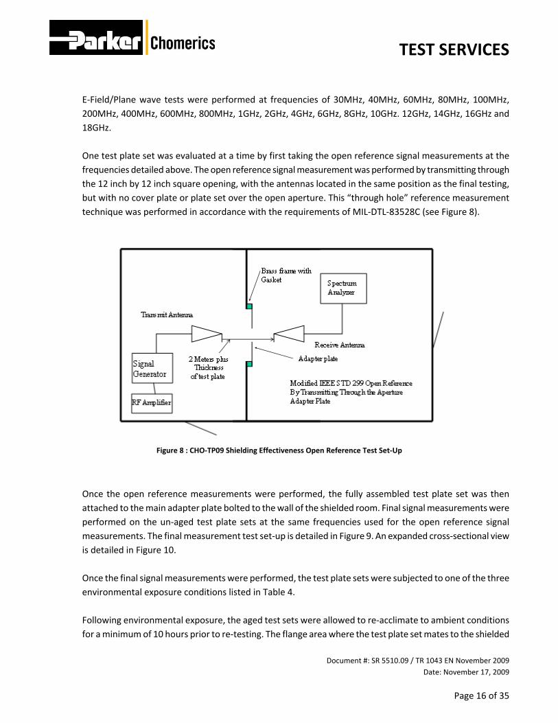
E‐Field/Plane wave tests were performed at frequencies of 30MHz, 40MHz, 60MHz, 80MHz, 100MHz, 200MHz, 400MHz, 600MHz, 800MHz, 1GHz, 2GHz, 4GHz, 6GHz, 8GHz, 10GHz. 12GHz, 14GHz, 16GHz and 18GHz. One test plate set was evaluated at a time by first taking the open reference signal measurements at the frequencies detailed above. The open reference signal measurement was performed by transmitting through the 12 inch by 12 inch square opening, with the antennas located in the same position as the final testing, but with no cover plate or plate set over the open aperture. This “through hole” reference measurement technique was performed in accordance with the requirements of MIL‐DTL‐83528C (see Figure 8).
Figure 8 : CHO‐TP09 Shielding Effectiveness Open Reference Test Set‐Up
Once the open reference measurements were performed, the fully assembled test plate set was then attached to the main adapter plate bolted to the wall of the shielded room. Final signal measurements were performed on the un‐aged test plate sets at the same frequencies used for the open reference signal measurements. The final measurement test set‐up is detailed in Figure 9. An expanded cross‐sectional view is detailed in Figure 10. Once the final signal measurements were performed, the test plate sets were subjected to one of the three environmental exposure conditions listed in Table 4. Following environmental exposure, the aged test sets were allowed to re‐acclimate to ambient conditions for a minimum of 10 hours prior to re‐testing. The flange area where the test plate set mates to the shielded

TEST SERVICES
Document #: SR 5510.09 / TR 1043 EN November 2009 Date: November 17, 2009
Page 17 of 35
enclosure was gently wiped with a coarse pad to help ensure the flange was clean and dry to optimize the electrical connection to the shielded enclosure. Open reference and final signal measurements were then repeated for each aged test plate set.
Figure 9 : CHO‐TP09 Shielding Effectiveness Final Measurement Test Set‐Up
Figure 10 : Expanded Cross Sectional View of CHO‐TP09 Test Plate Set‐Up

TEST SERVICES
Document #: SR 5510.09 / TR 1043 EN November 2009 Date: November 17, 2009
Page 18 of 35
5.3 Experimental Results Data Sheet 1 : Ni/Al CHO‐SEAL ‐ Initial Baseline SE
Date: Test No.: Test Spec.:
Type of Field Frequency
MHz Antenna
PolarizationOpen
ReferenceClosed
Shielding Effectiveness (dB)
Limits: Open Reference
E 30 H ‐37 ‐121 84 N/A Thru OpeningE 40 H ‐27 ‐111 84 N/A Thru OpeningE 60 H ‐10 ‐100 90 N/A Thru OpeningE 80 H ‐2 ‐93 91 N/A Thru OpeningE 100 H ‐8 ‐105 97 N/A Thru OpeningE 200 H 11 ‐91 102 N/A Thru OpeningE 400 C 21 ‐100 121 N/A Thru OpeningE 600 C 18 ‐103 121 N/A Thru OpeningE 800 C 13 ‐107 120 N/A Thru OpeningE 1,000 C 12 ‐107 119 N/A Thru OpeningP 2,000 V ‐17 ‐132 115 N/A Thru OpeningP 4,000 V 8 ‐106 114 N/A Thru OpeningP 6,000 V 7 ‐109 116 N/A Thru OpeningP 8,000 V ‐5 ‐124 119 N/A Thru OpeningP 10,000 V 3 ‐112 115 N/A Thru OpeningP 12,000 V ‐3 ‐115 112 N/A Thru OpeningP 14,000 V ‐2 ‐113 111 N/A Thru OpeningP 16,000 V ‐3 ‐108 105 N/A Thru OpeningP 18,000 V ‐23 ‐128 105 N/A Thru Opening
Comments:
1) Data averaged from four test samples2) Test data taken over four month period3) System noise floor is ‐135dBm
SHIELDING EFFECTIVENESS TEST DATA
Initial Baseline Data
Customer: Product Tested: Tested by: R&D Reference:
Parker Chomerics R&D 11/17/2009Ni/Al CHO‐SEAL 1Bill Couture TP‐09

TEST SERVICES
Document #: SR 5510.09 / TR 1043 EN November 2009 Date: November 17, 2009
Page 19 of 35
Data Sheet 2 : Ni/Al CHO‐SEAL ‐ SE After 2,000 Hours @ 125°C Dry Heat
Date: Test No.: Test Spec.:
Type of Field Frequency
MHz Antenna
PolarizationOpen
ReferenceClosed
Shielding Effectiveness (dB)
Limits: Open Reference
E 30 H ‐37 ‐121 84 N/A Thru OpeningE 40 H ‐27 ‐112 85 N/A Thru OpeningE 60 H ‐10 ‐101 91 N/A Thru OpeningE 80 H ‐2 ‐93 91 N/A Thru OpeningE 100 H ‐8 ‐106 98 N/A Thru OpeningE 200 H 11 ‐91 102 N/A Thru OpeningE 400 C 21 ‐98 119 N/A Thru OpeningE 600 C 18 ‐103 121 N/A Thru OpeningE 800 C 13 ‐106 119 N/A Thru OpeningE 1,000 C 12 ‐107 119 N/A Thru OpeningP 2,000 V ‐17 ‐131 114 N/A Thru OpeningP 4,000 V 8 ‐103 111 N/A Thru OpeningP 6,000 V 7 ‐104 111 N/A Thru OpeningP 8,000 V ‐5 ‐123 118 N/A Thru OpeningP 10,000 V 3 ‐113 116 N/A Thru OpeningP 12,000 V ‐3 ‐117 114 N/A Thru OpeningP 14,000 V ‐2 ‐114 112 N/A Thru OpeningP 16,000 V ‐3 ‐108 105 N/A Thru OpeningP 18,000 V ‐23 ‐128 105 N/A Thru Opening
Comments:
1) Data averaged from four test samples2) Test data taken over four month period3) System noise floor is ‐135dBm
Customer: Product Tested: Tested by: R&D Reference:
SHIELDING EFFECTIVENESS TEST DATA
After 2,000 Hours @ 125°C Dry Heat
Parker Chomerics R&D 11/17/2009Ni/Al CHO‐SEAL 2Bill Couture TP‐09

TEST SERVICES
Document #: SR 5510.09 / TR 1043 EN November 2009 Date: November 17, 2009
Page 20 of 35
Data Sheet 3 : Ni/Al CHO‐SEAL ‐ SE After 1,000 Hours @ 85°C & 85%RH
Date: Test No.: Test Spec.:
Type of Field Frequency
MHz Antenna
PolarizationOpen
ReferenceClosed
Shielding Effectiveness (dB)
Limits: Open Reference
E 30 H ‐37 ‐114 77 N/A Thru OpeningE 40 H ‐27 ‐106 79 N/A Thru OpeningE 60 H ‐10 ‐94 84 N/A Thru OpeningE 80 H ‐2 ‐87 85 N/A Thru OpeningE 100 H ‐8 ‐99 91 N/A Thru OpeningE 200 H 11 ‐91 102 N/A Thru OpeningE 400 C 21 ‐96 117 N/A Thru OpeningE 600 C 18 ‐95 113 N/A Thru OpeningE 800 C 13 ‐92 105 N/A Thru OpeningE 1,000 C 12 ‐96 108 N/A Thru OpeningP 2,000 V ‐17 ‐120 103 N/A Thru OpeningP 4,000 V 8 ‐101 109 N/A Thru OpeningP 6,000 V 7 ‐99 106 N/A Thru OpeningP 8,000 V ‐5 ‐107 102 N/A Thru OpeningP 10,000 V 3 ‐98 101 N/A Thru OpeningP 12,000 V ‐3 ‐105 102 N/A Thru OpeningP 14,000 V ‐2 ‐95 93 N/A Thru OpeningP 16,000 V ‐3 ‐94 91 N/A Thru OpeningP 18,000 V ‐23 ‐114 91 N/A Thru Opening
Comments:
1) Data averaged from four test samples2) Test data taken over four month period3) System noise floor is ‐135dBm
Customer: Product Tested: Tested by: R&D Reference:
SHIELDING EFFECTIVENESS TEST DATA
After 1,000 Hours @ 85°C & 85% RH
Parker Chomerics R&D 11/17/2009Ni/Al CHO‐SEAL 3Bill Couture TP‐09

TEST SERVICES
Document #: SR 5510.09 / TR 1043 EN November 2009 Date: November 17, 2009
Page 21 of 35
Data Sheet 4 : Ni/Al CHO‐SEAL ‐ SE After 500 Hrs Neutral (ASTM B117) Salt Fog
Date: Test No.: Test Spec.:
Type of Field Frequency
MHz Antenna
PolarizationOpen
ReferenceClosed
Shielding Effectiveness (dB)
Limits: Open Reference
E 30 H ‐37 ‐104 67 N/A Thru OpeningE 40 H ‐27 ‐94 67 N/A Thru OpeningE 60 H ‐10 ‐81 71 N/A Thru OpeningE 80 H ‐2 ‐77 75 N/A Thru OpeningE 100 H ‐8 ‐86 78 N/A Thru OpeningE 200 H 11 ‐76 87 N/A Thru OpeningE 400 C 21 ‐78 99 N/A Thru OpeningE 600 C 18 ‐76 94 N/A Thru OpeningE 800 C 13 ‐72 85 N/A Thru OpeningE 1,000 C 12 ‐74 86 N/A Thru OpeningP 2,000 V ‐17 ‐94 77 N/A Thru OpeningP 4,000 V 8 ‐80 88 N/A Thru OpeningP 6,000 V 7 ‐79 86 N/A Thru OpeningP 8,000 V ‐5 ‐86 81 N/A Thru OpeningP 10,000 V 3 ‐85 88 N/A Thru OpeningP 12,000 V ‐3 ‐85 82 N/A Thru OpeningP 14,000 V ‐2 ‐88 86 N/A Thru OpeningP 16,000 V ‐3 ‐94 91 N/A Thru OpeningP 18,000 V ‐23 ‐114 91 N/A Thru Opening
Comments:
1) Data averaged from four test samples2) Test data taken over four month period3) System noise floor is ‐135dBm
Customer: Product Tested: Tested by: R&D Reference:
SHIELDING EFFECTIVENESS TEST DATA
After 500 hrs Salt Fog
Parker Chomerics R&D 11/17/2009Ni/Al CHO‐SEAL 4Bill Couture TP‐09

TEST SERVICES
Document #: SR 5510.09 / TR 1043 EN November 2009 Date: November 17, 2009
Page 22 of 35
0
20
40
60
80
100
120
140
10 100 1,000 10,000 100,000
Attenuation (dB)
Frequency (MHz)
Typical Shielding Effectiveness Per CHO‐TP09Ni / Al Filled CHO‐SEAL
Initial / Dry Heat / Heat and Humidity / Salt Fog
Ni/Al Initial (Data Sheet # 1)
Ni/Al 2,000 hrs @ 125°C Dry Heat (Data Sheet # 2)
Ni/Al 1,000 hrs @ 85°C & 85% RH (Data Sheet # 3)
Ni/Al 500 hrs Salt Fog (Data Sheet # 4)0.177 inch high Solid D deflected 13%Al Flange Cr Coated per MIL‐C‐5541 Results typical for Hexa or Trivalent versions in Class 3
Figure 11 : Shielding Effectiveness: Ni/Al CHO‐SEAL ‐ Initial / Dry Heat / Humidity / Salt Fog

TEST SERVICES
Document #: SR 5510.09 / TR 1043 EN November 2009 Date: November 17, 2009
Page 23 of 35
Data Sheet 5 : Ag/Al CHO‐SEAL ‐ Initial Baseline SE
Date: Test No.: Test Spec.:
Type of Field Frequency
MHz Antenna
PolarizationOpen
ReferenceClosed
Shielding Effectiveness (dB)
Limits: Open Reference
E 30 H ‐37 ‐112 75 N/A Thru OpeningE 40 H ‐27 ‐105 78 N/A Thru OpeningE 60 H ‐10 ‐86 76 N/A Thru OpeningE 80 H ‐2 ‐82 80 N/A Thru OpeningE 100 H ‐8 ‐91 83 N/A Thru OpeningE 200 H 11 ‐80 91 N/A Thru OpeningE 400 C 21 ‐83 104 N/A Thru OpeningE 600 C 18 ‐81 99 N/A Thru OpeningE 800 C 13 ‐78 91 N/A Thru OpeningE 1,000 C 12 ‐80 92 N/A Thru OpeningP 2,000 V ‐17 ‐111 94 N/A Thru OpeningP 4,000 V 8 ‐90 98 N/A Thru OpeningP 6,000 V 7 ‐94 101 N/A Thru OpeningP 8,000 V ‐5 ‐109 104 N/A Thru OpeningP 10,000 V 3 ‐91 94 N/A Thru OpeningP 12,000 V ‐3 ‐97 94 N/A Thru OpeningP 14,000 V ‐2 ‐99 97 N/A Thru OpeningP 16,000 V ‐3 ‐102 99 N/A Thru OpeningP 18,000 V ‐23 ‐122 99 N/A Thru Opening
Comments:
1) Data averaged from four test samples2) Test data taken over four month period3) System noise floor is ‐135dBm
Customer: Product Tested: Tested by: R&D Reference:
SHIELDING EFFECTIVENESS TEST DATA
Initial Baseline Data
Parker Chomerics R&D 11/17/2009Ag/Al CHO‐SEAL 5Bill Couture TP‐09

TEST SERVICES
Document #: SR 5510.09 / TR 1043 EN November 2009 Date: November 17, 2009
Page 24 of 35
Data Sheet 6 : Ag/Al CHO‐SEAL ‐ SE After 2,000 Hours @ 125°C Dry Heat
Date: Test No.: Test Spec.:
Type of Field Frequency
MHz Antenna
PolarizationOpen
ReferenceClosed
Shielding Effectiveness (dB)
Limits: Open Reference
E 30 H ‐37 ‐102 65 N/A Thru OpeningE 40 H ‐27 ‐90 63 N/A Thru OpeningE 60 H ‐10 ‐74 64 N/A Thru OpeningE 80 H ‐2 ‐71 69 N/A Thru OpeningE 100 H ‐8 ‐76 68 N/A Thru OpeningE 200 H 11 ‐69 80 N/A Thru OpeningE 400 C 21 ‐71 92 N/A Thru OpeningE 600 C 18 ‐66 84 N/A Thru OpeningE 800 C 13 ‐68 81 N/A Thru OpeningE 1,000 C 12 ‐69 81 N/A Thru OpeningP 2,000 V ‐17 ‐103 86 N/A Thru OpeningP 4,000 V 8 ‐81 89 N/A Thru OpeningP 6,000 V 7 ‐89 96 N/A Thru OpeningP 8,000 V ‐5 ‐92 87 N/A Thru OpeningP 10,000 V 3 ‐84 87 N/A Thru OpeningP 12,000 V ‐3 ‐85 82 N/A Thru OpeningP 14,000 V ‐2 ‐86 84 N/A Thru OpeningP 16,000 V ‐3 ‐97 94 N/A Thru OpeningP 18,000 V ‐23 ‐117 94 N/A Thru Opening
Comments:
1) Data averaged from four test samples2) Test data taken over four month period3) System noise floor is ‐135dBm
Customer: Product Tested: Tested by: R&D Reference:
SHIELDING EFFECTIVENESS TEST DATA
After 2,000 Hours @ 125°C Dry Heat
Parker Chomerics R&D 11/17/2009Ag/Al CHO‐SEAL 6Bill Couture TP‐09

TEST SERVICES
Document #: SR 5510.09 / TR 1043 EN November 2009 Date: November 17, 2009
Page 25 of 35
Data Sheet 7 : Ag/Al CHO‐SEAL ‐ SE After 1,000 Hours @ 85°C & 85%RH
Date: Test No.: Test Spec.:
Type of Field Frequency
MHz Antenna
PolarizationOpen
ReferenceClosed
Shielding Effectiveness (dB)
Limits: Open Reference
E 30 H ‐37 ‐81 44 N/A Thru OpeningE 40 H ‐27 ‐72 45 N/A Thru OpeningE 60 H ‐10 ‐55 45 N/A Thru OpeningE 80 H ‐2 ‐51 49 N/A Thru OpeningE 100 H ‐8 ‐62 54 N/A Thru OpeningE 200 H 11 ‐53 64 N/A Thru OpeningE 400 C 21 ‐51 72 N/A Thru OpeningE 600 C 18 ‐55 73 N/A Thru OpeningE 800 C 13 ‐54 67 N/A Thru OpeningE 1,000 C 12 ‐55 67 N/A Thru OpeningP 2,000 V ‐17 ‐99 82 N/A Thru OpeningP 4,000 V 8 ‐79 87 N/A Thru OpeningP 6,000 V 7 ‐70 77 N/A Thru OpeningP 8,000 V ‐5 ‐74 69 N/A Thru OpeningP 10,000 V 3 ‐75 78 N/A Thru OpeningP 12,000 V ‐3 ‐78 75 N/A Thru OpeningP 14,000 V ‐2 ‐88 86 N/A Thru OpeningP 16,000 V ‐3 ‐83 80 N/A Thru OpeningP 18,000 V ‐23 ‐103 80 N/A Thru Opening
Comments:
1) Data averaged from four test samples2) Test data taken over four month period3) System noise floor is ‐135dBm
Customer: Product Tested: Tested by: R&D Reference:
SHIELDING EFFECTIVENESS TEST DATA
After 1,000 Hours @ 85°C & 85% RH
Parker Chomerics R&D 11/17/2009Ag/Al CHO‐SEAL 7Bill Couture TP‐09

TEST SERVICES
Document #: SR 5510.09 / TR 1043 EN November 2009 Date: November 17, 2009
Page 26 of 35
Data Sheet 8 : Ag/Al CHO‐SEAL ‐ SE After 500 Hrs Neutral (ASTM B117) Salt Fog
Date: Test No.: Test Spec.:
Type of Field Frequency
MHz Antenna
PolarizationOpen
ReferenceClosed
Shielding Effectiveness (dB)
Limits: Open Reference
E 30 H ‐37 ‐84 47 N/A Thru OpeningE 40 H ‐27 ‐71 44 N/A Thru OpeningE 60 H ‐10 ‐54 44 N/A Thru OpeningE 80 H ‐2 ‐47 45 N/A Thru OpeningE 100 H ‐8 ‐55 47 N/A Thru OpeningE 200 H 11 ‐49 60 N/A Thru OpeningE 400 C 21 ‐52 73 N/A Thru OpeningE 600 C 18 ‐57 75 N/A Thru OpeningE 800 C 13 ‐57 70 N/A Thru OpeningE 1,000 C 12 ‐56 68 N/A Thru OpeningP 2,000 V ‐17 ‐88 71 N/A Thru OpeningP 4,000 V 8 ‐79 87 N/A Thru OpeningP 6,000 V 7 ‐77 84 N/A Thru OpeningP 8,000 V ‐5 ‐84 79 N/A Thru OpeningP 10,000 V 3 ‐79 82 N/A Thru OpeningP 12,000 V ‐3 ‐70 67 N/A Thru OpeningP 14,000 V ‐2 ‐74 72 N/A Thru OpeningP 16,000 V ‐3 ‐86 83 N/A Thru OpeningP 18,000 V ‐23 ‐106 83 N/A Thru Opening
Comments:
1) Data averaged from four test samples2) Test data taken over four month period3) System noise floor is ‐135dBm
Customer: Product Tested: Tested by: R&D Reference:
SHIELDING EFFECTIVENESS TEST DATA
After 500 hrs Salt Fog
Parker Chomerics R&D 11/17/2009Ag/Al CHO‐SEAL 8Bill Couture TP‐09

TEST SERVICES
Document #: SR 5510.09 / TR 1043 EN November 2009 Date: November 17, 2009
Page 27 of 35
0
20
40
60
80
100
120
140
10 100 1,000 10,000 100,000
Attenuation (dB)
Frequency (MHz)
Typical Shielding Effectiveness Per CHO‐TP09Ag / Al Filled CHO‐SEAL
Initial / Dry Heat / Heat and Humidity / Salt Fog
Ag/Al Initial (Data Sheet # 5)
Ag/Al 2,000 hrs @ 125°C Dry Heat (Data Sheet # 6)
Ag/Al 1,000 hrs @ 85°C & 85% RH (Data Sheet # 7)
Ag/Al 500 hrs Salt Fog (Data Sheet # 8)
0.177 inch high Solid D deflected 13%Al Flange Cr Coated per MIL‐C‐5541 Results typical for Hexa or Tri valent versions in Class 3
Figure 12 : Shielding Effectiveness: Ag/Al CHO‐SEAL ‐ Initial / Dry Heat / Humidity / Salt Fog

TEST SERVICES
Document #: SR 5510.09 / TR 1043 EN November 2009 Date: November 17, 2009
Page 28 of 35
0
20
40
60
80
100
120
140
10 100 1,000 10,000 100,000
Attenuation (dB)
Frequency (MHz)
Typical Shielding Effectiveness Per CHO‐TP09Ni/Al versus Ag/Al Filled CHO‐SEAL
Initial Baseline
Ni/Al Initial (Data Sheet # 1)
Ag/Al Initial (Data Sheet # 5)0.177 inch high Solid D deflected 13%Al Flange Cr Coated per MIL‐C‐5541 Results typical for Hexa or Trivalent versions in Class 3
Figure 13 : Shielding Effectiveness Comparison: Ni/Al vs. Ag/Al ‐ Initial Baseline

TEST SERVICES
Document #: SR 5510.09 / TR 1043 EN November 2009 Date: November 17, 2009
Page 29 of 35
0
20
40
60
80
100
120
140
10 100 1,000 10,000 100,000
Attenuation (dB)
Frequency (MHz)
Typical Shielding Effectiveness Per CHO‐TP09Ni/Al versus Ag/Al Filled CHO‐SEALAged 2,000 Hours at 125°C Dry Heat
Ni/Al 2,000 hrs @ 125°C Dry Heat (Data Sheet # 2)
Ag/Al 2,000 hrs @ 125°C Dry Heat (Data Sheet # 6)0.177 inch high Solid D deflected 13%Al Flange Cr Coated per MIL‐C‐5541 Results typical for Hexa or Trivalent versions in Class 3
Figure 14 : Shielding Effectiveness Comparison: Ni/Al vs. Ag/Al ‐ 2,000 Hours @ 125°C Dry Heat

TEST SERVICES
Document #: SR 5510.09 / TR 1043 EN November 2009 Date: November 17, 2009
Page 30 of 35
0
20
40
60
80
100
120
140
10 100 1,000 10,000 100,000
Attenuation (dB)
Frequency (MHz)
Typical Shielding Effectiveness Per CHO‐TP09Ni/Al versus Ag/Al Filled CHO‐SEALAged 1,000 Hours at 85°C / 85%RH
Ni/Al 1,000 hrs @ 85°C & 85% RH (Data Sheet # 3)
Ag/Al 1,000 hrs @ 85°C & 85% RH (Data Sheet # 7)0.177 inch high Solid D deflected 13%Al Flange Cr Coated per MIL‐C‐5541 Results typical for Hexa or Trivalent versions in Class 3
Figure 15 : Shielding Effectiveness Comparison: Ni/Al vs. Ag/Al ‐ 1,000 Hours @ 85°C & 85% RH

TEST SERVICES
Document #: SR 5510.09 / TR 1043 EN November 2009 Date: November 17, 2009
Page 31 of 35
0
20
40
60
80
100
120
140
10 100 1,000 10,000 100,000
Attenuation (dB)
Frequency (MHz)
Typical Shielding Effectiveness Per CHO‐TP09Ni/Al versus Ag/Al Filled CHO‐SEAL
Aged 500 Hours at 35°C Neutral (ASTM B117) Salt Fog
Ni/Al 500 hrs Salt Fog (Data Sheet # 4)
Ag/Al 500 hrs Salt Fog (Data Sheet # 8)0.177 inch high Solid D deflected 13%Al Flange Cr Coated per MIL‐C‐5541 Results typical for Hexa or Trivalent versions in Class 3
Figure 16 : Shielding Effectiveness Comparison: Ni/Al vs. Ag/Al ‐ 500 Hours @ Salt Fog

TEST SERVICES
Document #: SR 5510.09 / TR 1043 EN November 2009 Date: November 17, 2009
Page 32 of 35
5.4 Conclusions
The test data included within this report illustrates that CHO‐SEAL Ni/Al filled materials are superior in shielding effectiveness before and after environmental exposure compared to the CHO‐SEAL Ag/Al filled equivalent. As noted in the report, two different types of chromate conversion coatings were evaluated against both molded and extruded forms of CHO‐SEAL 6502, a nickel‐plated aluminum filled silicone and CHO‐SEAL 6503, the Ni/Al filled fluorosilicone equivalent. These materials were similarly evaluated against CHO‐SHIELD 1298, a silver‐plated aluminum filled fluorosilicone gasket material. The evaluation demonstrated that within several dB, the shielding effectiveness was equivalent regardless of chromate flange treatment, elastomer binder or product form. Inclusion of the entire test package within this report was not practical, nor necessary to support this conclusion. The test data sheets and shielding effectiveness curves shown herein are a composite of results taken over several months of testing on a variety of gasket materials, flange treatments and environmental exposure conditions. Requests for specific test data shall be made through the Parker Chomerics Applications Lab or Test Services.

TEST SERVICES
Document #: SR 5510.09 / TR 1043 EN November 2009 Date: November 17, 2009
Page 33 of 35
6 Photographic Documentation CUSTOMER: PARKER CHOMERICS R&D DATE: 11/17/2009 MATERIAL: CHO‐SEAL NI/AL AND CHO‐SEAL AG/AL TEST NUMBER: ALL TESTED BY: WILLIAM COUTURE COUPLING DEVICE: BICONICAL ANTENNA OPERATING MODE: N/A TEST SPEC: CHO‐TP09
Photograph Description: Basic Thru‐Hole Open Reference Setup 20MHz to 200MHz
FORM CTS‐PHOTO

TEST SERVICES
Document #: SR 5510.09 / TR 1043 EN November 2009 Date: November 17, 2009
Page 34 of 35
CUSTOMER: PARKER CHOMERICS R&D DATE: 11/17/2009 MATERIAL: CHO‐SEAL NI/AL AND CHO‐SEAL AG/AL TEST NUMBER: ALL TESTED BY: WILLIAM COUTURE COUPLING DEVICE: LOG SPIRAL ANTENNA OPERATING MODE: N/A TEST SPEC: CHO‐TP09
Photograph Description: Basic Thru‐Hole Open Reference Setup 200MHz to 1GHz
FORM CTS‐PHOTO

TEST SERVICES
Document #: SR 5510.09 / TR 1043 EN November 2009 Date: November 17, 2009
Page 35 of 35
CUSTOMER: PARKER CHOMERICS R&D DATE: 11/17/2009 MATERIAL: CHO‐SEAL NI/AL AND CHO‐SEAL AG/AL TEST NUMBER: ALL TESTED BY: WILLIAM COUTURE COUPLING DEVICE: HORN ANTENNA OPERATING MODE: N/A TEST SPEC: CHO‐TP09
Photograph Description: Basic Thru‐Hole Open Reference Setup 1GHz to 18GHz
FORM CTS‐PHOTO