2010 mars sample return orbiter decadal survey - nap.edu g 08_mars-sample-return...table 3-4....
TRANSCRIPT

Planetary Science Decadal Survey
MSR Orbiter Mission (Including Mars Returned Sample Handling)
Science Champion: Phil Christensen ([email protected])
NASA HQ POC: Lisa May ([email protected])
March 2010
Mission Concept Study Mission Concept Study
National Aeronautics and Space Administration
www.nasa.gov
Planetary Science Decadal Survey
MSR Orbiter Mission (Including Mars Returned Sample Handling)
Science Champion: Phil Christensen ([email protected])
NASA HQ POC: Lisa May ([email protected])
March 2010

MSR Orbiter Mission i
Data Release, Distribution, and Cost Interpretation Statements This document is intended to support the SS2012 Planetary Science Decadal Survey.
The data contained in this document may not be modified in any way.
Cost estimates described or summarized in this document were generated as part of a preliminary concept study, are model-based, assume a JPL in-house build, and do not constitute a commitment on the part of JPL or Caltech. References to work months, work years, or FTEs generally combine multiple staff grades and experience levels.
Cost reserves for development and operations were included as prescribed by the NASA ground rules for the Planetary Science Decadal Survey. Unadjusted estimate totals and cost reserve allocations would be revised as needed in future more-detailed studies as appropriate for the specific cost-risks for a given mission concept.

MSR Orbiter Mission ii
Planetary Science Decadal Survey Mission Concept Study Final Report
Acknowledgments ........................................................................................................ iv
Executive Summary ...................................................................................................... v
Mission Concept ........................................................................................................................... v
Key Technologies and Risks ......................................................................................................... v
1. Scientific Objectives ............................................................................................ 1
Science Questions and Objectives ............................................................................................... 1
Science Traceability ...................................................................................................................... 1
2. High-Level Mission Concept ............................................................................... 2
Overview ....................................................................................................................................... 2
Concept Maturity Level ................................................................................................................. 2
Technology Maturity ...................................................................................................................... 3
Key Trades .................................................................................................................................... 3
3. Technical Overview .............................................................................................. 4
Instrument Payload Description .................................................................................................... 4
Flight System ................................................................................................................................ 4
Concept of Operations and Mission Design ................................................................................ 10
Planetary Protection .................................................................................................................... 13
Risk List ...................................................................................................................................... 13
4. Development Schedule and Schedule Constraints ......................................... 16
High-Level Mission Schedule ...................................................................................................... 16
Technology Development Plan ................................................................................................... 17
Development Schedule and Constraints ..................................................................................... 18
5. Mission Life-Cycle Cost ..................................................................................... 19
Costing Methodology and Basis of Estimate .............................................................................. 19
Cost Estimates ............................................................................................................................ 19
MSR Orbiter Mission iii
Figures Figure 3-1 Preliminary Orbiter Configuration ................................................................................................ 5
Figure 3-2. Rendezvous and Capture System Designs ................................................................................ 7
Figure 3-3. Earth Entry Vehicle Preliminary Design ..................................................................................... 8
Figure 3-4. Mars Returned Sample Handling Concept ............................................................................... 10
Figure 3-5. Generic Mission Timeline ......................................................................................................... 12
Figure 3-6. 5 x 5 Risk Matrix ....................................................................................................................... 14
Figure 4-1. Development Schedule for the Proposed Orbiter Mission and MRSH ..................................... 16
Tables Table 2-1. Concept Maturity Level Definitions .............................................................................................. 3
Table 3-1. Orbiter Bus Mass and Power Estimates ...................................................................................... 5
Table 3-2. Preliminary Orbiter Characteristics .............................................................................................. 6
Table 3-3. Earth Entry Vehicle Mass and Power Estimate ........................................................................... 9
Table 3-4. Mission Design Concept ............................................................................................................ 11
Table 3-5. Comparitive Mission Parameters ............................................................................................... 11
Table 3-6. Mission Operations and Ground Data Systems ........................................................................ 12
Table 3-7. Top Risks for the Proposed Orbiter Mission and MRSH ........................................................... 14
Table 3-8. Risk Level Definitions ................................................................................................................ 15
Table 4-1. Proposed Key Phase Duration .................................................................................................. 16
Table 5-1. Total Estimated Mission Cost Funding Profile ........................................................................... 20
Appendices
A. Acronyms
B. References
C. Orbiter Master Equipment List from Team X Study
D. Sample Receiving Facility Planning Article

MSR Orbiter Mission iv
Acknowledgments This report was authored by Richard Mattingly, Jet Propulsion Laboratory, California Institute of Technology.
This research was carried out at the Jet Propulsion Laboratory, California Institute of Technology, under a contract with the National Aeronautics and Space Administration.
© 2010. All rights reserved.
MSR Orbiter Mission v
Executive Summary The Mars Sample Return (MSR) concept is a campaign of three missions: a sample acquisition/caching rover mission, a lander mission to fetch the cache and deliver it to Mars orbit via a rocket, and an orbiter that would capture the orbiting sample (OS) container and deliver it to Earth via an Earth entry vehicle (EEV). A fourth component is the Mars Returned Sample Handling (MRSH) element that would include a sample receiving facility (SRF) and a curation facility. These elements are represented in three separate mission concept study reports:
Mars 2018 MAX-C Caching Rover [1]
MSR Lander Mission [2]
MSR Orbiter Mission (including MRSH)
The latter concept is the subject of this report.
The overall objective of the proposed MSR campaign would be to collect samples of Mars (mainly rock cores) and return them to Earth for in-depth analysis in terrestrial laboratories. The objective of the Orbiter Mission would be to rendezvous with and capture an OS container that would have been deposited into a 500 km circular orbit by the MSR Lander Mission and land the samples on Earth via an EEV. The MRSH project objective would be to contain the EEV, transport it to an SRF for quarantine, apply a test protocol to assess potential hazards of the samples, and curate the samples for further distribution. The Orbiter Mission and MRSH project must meet the planetary protection requirements of a restricted Earth-return mission.
While the MSR campaign might be an international endeavor, this report assumes that the Orbiter Mission would be performed by NASA and that the samples would be returned, contained, and assessed in the continental United States.
Mission Concept The orbiter would be launched on a medium-class vehicle on a trajectory that would reach Mars in ~9 months, and would aerobrake to a 500 km circular orbit over 6–9 months. Current plans have the orbiter arriving at Mars ~2 years before the MSR lander; it then could perform critical event coverage as well as telecom relay for the lander and its fetch rover. After ~6 months, the Mars ascent vehicle (MAV) would place the OS in a 500 km circular orbit comparable to the orbiter orbit. The orbiter would detect and track the OS, while maneuvering to rendezvous. The OS would be captured by the orbiter, sealed, and placed in an EEV. The orbiter would leave Mars on a non-impact trajectory to Earth, and shortly before arrival, target Earth, release the EEV, then divert away from Earth. The EEV would enter and hard land at a recovery site to be determined (baselined to be the Utah Test and Training Range [UTTR], decision pending the National Environmental Policy Act [NEPA] process and agreement with the U.S. Air Force).
The MRSH element would then be responsible for safe transport of the EEV to an SRF, where the hardware and samples would remain in quarantine until determined to be safe by applying a testing protocol. If safe, the samples would be released to a curation facility for safe keeping and distribution to scientists and laboratories worldwide. While they are not costed in this study, options for conducting science in the SRF are being considered in the event the samples are not deemed safe to release.
Key Technologies and Risks The MSR Orbiter Mission concept uses the heritage and experience from a decade of orbiters at Mars. Rendezvous and capture at Mars is new, but concerns are mitigated by the experience of the Defense Advanced Research Projects Agency (DARPA) Orbital Express mission, which performed detection and rendezvous in Earth orbit under very similar conditions, and demonstration of an MSR capture basket concept on a zero-g aircraft campaign. Early development and testing of the EEV concept has taken the design far enough to mitigate concerns. The biggest challenge ahead is meeting the planetary protection requirements for a restricted Earth-return mission (termed back planetary protection [BPP]). A

MSR Orbiter Mission vi
probabilistic risk assessment (PRA) has indicated where technology developments are needed, some of which are reflected in the EEV concept. While basic techniques have been demonstrated in labs, components for sealing, leak detection, and dust mitigation still need to be brought up to technology readiness level (TRL) 6. The biggest development risk to the project is demonstrating that it can meet the BPP requirements.

MSR Orbiter Mission 1
1. Scientific Objectives Science Questions and Objectives The Orbiter Mission is part of the Mars Sample Return (MSR) campaign concept, which would provide the transportation of a prepackaged and sealed cache of samples back to Earth. The proposed science objectives are described in the MAX-C and MSR lander mission concept studies [1, 2]. Two mission considerations relate to science integrity:
1. The sample cache should be kept below 20°C, except for a short period of time (one hour) after landing, where it could be allowed to rise to 50°C, with a goal of maintaining 20°C. This would be obtained passively both on the orbiter and the Earth entry vehicle (EEV). During free-flight, the orbiting sample (OS) container would always be around -50°C, so there would be no need to quickly capture it. Upon returning to Earth’s surface, the temperature rise would be the worst case due to heat soak-back from entry and the more significant ambient input of sitting in the sun. Reaching the EEV and putting it into a cooled vault within approximately one hour would mitigate the temperature rise and would also be desirable for planetary protection.
2. Upon landing, shock should be kept to within 2,500 g’s. The samples would be constrained inside sample tubes to maintain sample stratification. Drop tests of the EEV test models at the proposed (decision pending) landing site, Utah Training and Test Range (UTTR), have demonstrated that the EEV energy-absorbing impact materials can meet this need.
The Mars Returned Sample Handling (MRSH) element would have to ensure the same level of temperature control for the samples. Moreover, the samples would have to be kept isolated from terrestrial contaminants and each other. Standard methods of curation and clean handling common to semi-conductor, medical industries, and astromaterials curation/analysis would be applied.
Science Traceability The science traceability matrix is not included in this report because there is no science planned for the Orbiter Mission.

MSR Orbiter Mission 2
2. High-Level Mission Concept Overview The Orbiter Mission is one of three missions comprising the proposed MSR campaign. Samples would be collected and cached by the first mission, MAX-C, preliminarily planned for a 2018 launch. A sample cache (two canisters for redundancy) would be left on the surface of Mars for possible later retrieval. The orbiter would be launched nominally in 2022 on a medium-class vehicle reaching Mars in ~9 months. The orbiter would insert into a highly elliptical orbit and aerobrake down to a 500 km circular orbit over 6–9 months. The third mission of the proposed MSR campaign, the lander, would nominally be launched in 2024, which would be the next opportunity to get to Mars. The orbiter would provide critical event coverage of the lander entry/descent/landing (EDL), and provide telecom relay for the proposed lander and its fetch rover dispatched to retrieve the sample cache. Approximately 6 months after lander arrival, the OS container would be launched by a Mars ascent vehicle (MAV) and the OS would be released in a 500 km orbit comparable with the orbiter. This is all part of the Lander Mission concept. The orbiter would provide critical event coverage of the MAV ascent and OS release and capture.
Using an optical camera, the orbiter would detect and track the OS, while maneuvering to rendezvous. The OS would be captured via a basket, sealed into an outer container, and placed in an EEV. Nominally, within ~3 months, the orbiter would leave Mars on a non-impact trajectory to Earth, and shortly before arrival, would target Earth, release the EEV, and then divert away from Earth. The EEV would enter and hard land at a recovery site to be determined (baselined to be UTTR, decision pending the National Environmental Policy Act [NEPA] process and agreement with the U.S. Air Force). This return trajectory and EDL sequence is similar to the Genesis and Stardust missions, except it would not have a parachute.
The MRSH element would then be responsible for safe transport of the EEV to a sample receiving facility (SRF), where the hardware and samples would remain in quarantine until they are determined to be safe (either by their nature or sterilized). A testing protocol would be applied to the samples to determine if they are safe for release. This might take approximately one year and is considered part of the MRSH element. If the samples are determined to be non-hazardous to Earth’s biosphere, the samples would be released to a curation facility for safe keeping and distribution to the international science community. A nominal cost is included for such a facility, potentially part of the current NASA Johnson Space Center (JSC) curation facilities. While they are not costed in this study, options for conducting science in the SRF are being considered in the event the samples are not deemed safe to release.
The orbiter was designed and costed by JPL’s Team X, assuming an in-house build. Alternatively, the orbiter could be built by an industry partner, or provided by ESA as part of an ongoing international partnership on Mars missions. The EEV most likely would be provided by NASA Langley Research Center (LaRC), the developers of the EEV to this point. MRSH would be implemented by NASA with potential help from other agencies for safe transport of the EEV. A new SRF is planned, but augmentation to an existing bio-safety level-4 (BSL-4) lab would be considered. Curation nominally would fall under the auspices of the existing Astromaterials Curation Laboratory at the NASA JSC, and could be part of the SRF. Although, not considered in this report, ESA could provide support or parallel facilities for MRSH.
Concept Maturity Level Table 2-1 summarizes the NASA definitions for concept maturity levels (CMLs). The flight systems concept is at a maturity level of CML 4.
The orbiter concept has been through several iterative Team X studies, and is mostly based on Mars orbiters currently flying. The EEV was brought to a detailed conceptual design by NASA LaRC in 2002, and the design is still judged to be valid and appropriate for the mission.
The MRSH element is based on studies performed by three industrial teams in 2005, establishing and evaluating conceptual plans. This element is at CML 3.

MSR Orbiter Mission 3
Table 2-1. Concept Maturity Level Definitions Concept
Maturity Level Definition Attributes CML 6 Final Implementation
Concept Requirements trace and schedule to subsystem level, grassroots cost, V&V approach for key areas
CML 5 Initial Implementation Concept
Detailed science traceability, defined relationships and dependencies: partnering, heritage, technology, key risks and mitigations, system make/buy
CML 4 Preferred Design Point Point design to subsystem level mass, power, performance, cost, risk
CML 3 Trade Space Architectures and objectives trade space evaluated for cost, risk, performance
CML 2 Initial Feasibility Physics works, ballpark mass and cost CML 1 Cocktail Napkin Defined objectives and approaches, basic architecture
concept
Technology Maturity The Orbiter Mission would use the heritage and experience from a decade of orbiters at Mars. The orbiter bus, per se, would have no new technologies. Rendezvous and capture at Mars would be new, but concerns are mitigated by the experience of the DARPA Orbital Express mission, which performed detection, rendezvous, and capture in Earth orbit under very similar conditions, and demonstration of a MSR capture basket concept on a zero-g aircraft campaign. While the required rendezvous components have heritage from prior programs, integration as a system would still be required. The capture system would still need further development and integration with the rendezvous system would need to be demonstrated to reach technology readiness level (TRL) 6 by Preliminary Design Review (PDR).
Early development and testing of the EEV concept has taken the design far enough to mitigate concerns. The biggest challenge ahead is meeting the planetary protection requirements for a restricted Earth-return mission (termed BPP). A PRA has indicated where development is needed, some of which has been satisfied by the EEV concept. While basic techniques have been demonstrated in labs, components for sealing, leak detection, and dust mitigation still need to be brought up to TRL 6. In addition, the design of the EEV needs to be refreshed and the system developed to the point that it could be flight tested, if needed, by PDR.
Key Trades Many trade studies for MSR have been performed over the last decade. For the orbiter concept, main trades have included potential use of solar electric propulsion (which would not be mission enabling), a rendezvous location (500 km circular being a good match for the proposed MAV capability vs. deep-space or high-altitude), direct entry at Earth (vs. returning to the Space Station or Earth orbit, neither of which meets the reliability needed for planetary protection), and passive optical rendezvous sensing (simple, reliable and adequate vs. active systems).
Orbiter implementation approach details still have open trades, which would be resolved after selection of the implementer (a NASA center, industry, or the European Space Agency [ESA]). The largest looming trade is staging of the propulsion system, either after Mars Orbit Insertion (MOI), Trans-Earth Injection (TEI), or both. While these alternate staging designs have been analyzed (and result in lower launch mass), a single stage is baselined in this report as being the most conservative.
The main trades of MRSH implementation would involve the SRF and curation facility. The SRF might either be a new stand-alone facility or an augmentation to an existing BSL-4 laboratory (budget assumes a new facility). The curation facility might either be part of the SRF or a new lab built in conjunction to existing NASA JSC curation labs (assumed in the budget). Potential partnership with ESA might lead to their support to either, or even provision of parallel labs.
MSR Orbiter Mission 4
3. Technical Overview Instrument Payload Description It is assumed there are no science instruments proposed for MSR Orbiter.
Instrumentation for planetary protection (not science) sample hazard testing in the SRF is included in the cost provided by industry teams, as part of the facility.
Flight System The description is divided into two flight systems—the orbiter bus with a rendezvous/capture subsystem and the EEV.
Orbiter The series of Mars orbiters (Mars Global Surveyor [MGS], Odyssey [ODY], Mars Reconnaissance Orbiter [MRO]) over the last decade lay the foundation for the proposed MSR Orbiter, including bus subsystems, complex operations at Mars, aerobraking (needed to reduce fuel requirements), and telecomm relay for assets on the surface.
The primary function of the orbiter would be to detect, rendezvous, and capture the OS, transfer the OS to an EEV, then target and release the EEV to Earth for entry. This would all need to be performed in a manner consistent with the planetary protection of Earth (discussed in the Planetary Protection section).
Depending on whether there are adequate telecomm assets at Mars for critical event coverage and surface vehicle telecomm relay, the orbiter might need to provide this function, in which case it would have to be early in the mission sequence as baselined. The orbiter would have redundant Electra telecomm relay systems and an X-band Small Deep Space Transponder Earth link with a 2-axis gimbaled 1 m high-gain antenna. Electra is the standard programmable radio that has flown on MRO. It has a highly sensitive broadband-receiving mode originally designed for monitoring a potential ultra-high frequency (UHF) beacon on the OS, which might be included for backup.
Even with the benefit of aerobraking to reduce MOI propulsive requirements, fuel would comprise approximately two thirds of the orbiter’s mass because of the additional need to perform a TEI to return. A bi-propellant system would be utilized for efficiency, like MGS. Figure 3-1 shows the baseline orbiter concept developed by JPL’s Team X. While the baseline in this report assumes one EEV, the configuration shows accommodation of two. Table 3-1 provides a mass summary and Table 3-2 lists the proposed orbiter characteristics. The bulk of the configuration would be a large central hydrazine fuel tank with two outboard NTO oxidizer tanks. A reaction control system (RCS) for attitude control would use hydrazine only. Power would be provided by a single 4.3 m diameter Ultraflex solar array, and a second dummy (unpopulated) array would be added to provide additional cross-sectional area (more drag) to keep the aerobraking period within 6–9 months. Except for the payload (rendezvous hardware and EEV), all other subsystems would be standard heritage hardware, depending on the integrator (a NASA center, industry, or ESA). The specifics in this report assume JPL in-house implementation consistent with standard Team X study assumptions. The baseline design is redundant throughout.
MSR Orbiter Mission 5
Solar Panel 15m2
UHF
CamerasSample Capture And Transfer
Aerobrake Panel (no cells) 15m2
EEV
1m HGA
Star Scanners
4x 200lb Hi-Pat Thrusters
Prop Tanks
Pressurant Tanks
Figure 3-1 Preliminary Orbiter Configuration
Table 3-1. Orbiter Bus Mass and Power Estimates
Mass Average Power
CBE (kg) % Cont.
MEV (kg)
CBE (W) % Cont.
MEV (W)
Structures & mechanisms 260.9 30% 339.2 - - - Orbiter launch vehicle adapter 22.6 30% 29.3 - - - Thermal control 28.1 27% 35.6 67 43% 96 Propulsion (dry mass) 137.5 25% 171.9 69 43% 99 Attitude control 29.0 21% 35.1 66 43% 94 Command & data handling 20.4 30% 26.6 40 43% 57 Telecommunications 29.1 13% 32.9 145 43% 207 Power 98.8 30% 128.4 57 43% 81 Cabling 33.0 30% 42.9 - - - System contingency - - 101.1 - - - Total Orbiter Dry Bus Mass 659.4 43% 942.9 444 43% 634

MSR Orbiter Mission 6
Table 3-2. Preliminary Orbiter Characteristics Flight System Element Parameters (as appropriate) Value/ Summary, units
General Design life, months 5 years Structure Structures material (aluminum, exotic, composite, etc.) Primarily aluminum Number of articulated structures 1 HGA, 1 capture door,
1 solar array, 2 rendezvous sensor
Number of deployed structures 2 solar arrays Thermal Control Type of thermal control used Passive with heaters Propulsion Estimated delta-V budget, m/s 3,690 m/s Propulsion type(s) and associated propellant(s)/oxidizer(s) N2H4 + NTO Number of thrusters and tanks 4 x 890 N biprop main,
16 x 0.7 N mono RCS, 1 NTO tank, 2 N2H4 tanks
Specific impulse of each propulsion mode, seconds 325 s main, 210 s RCS Attitude Control Control method (3-axis, spinner, grav-gradient, etc.). 3-axis Control reference (solar, inertial, Earth-nadir, Earth-limb, etc.) Flight vector Attitude control capability, degrees 505 arcsec Attitude knowledge limit, degrees 252 arcsec Agility requirements (maneuvers, scanning, etc.) 6.2 arcsec/sec stability Articulation/#–axes (solar arrays, antennas, gimbals, etc.) HGA 2DOF, one solar
array 1DOF Sensor and actuator information (precision/errors, torque, momentum storage capabilities, etc.)
0.5 deg sun sensors, 6 arcsec star trackers,
0.005 deg/hr MIMU Command & Data Handling Flight element housekeeping data rate, kbps Low Data storage capacity, Mbits 4 GB Maximum storage record rate, kbps 8 Mbits/s Maximum storage playback rate, kbps 8 Mbits/s Power Type of array structure (rigid, flexible, body mounted, deployed, articulated) Deployed UltraFlex Array size, meters x meters 15 m2 Solar cell type (Si, GaAs, multi-junction GaAs, concentrators) GaAs Expected power generation at beginning of life (BOL) and end of life (EOL), watts
1257 W BOL, 1124 W EOL
On-orbit average power consumption, watts 634 W Battery type (NiCd, NiH, Li-ion) Li-ion Battery storage capacity, amp-hours 96 A-Hr

MSR Orbiter Mission 7
Rendezvous and capture of a free-orbiting OS would be performed by the orbiter after aerobraking is complete. An optical navigation (OpNav) camera, demonstrated on MRO would be used to find and track the OS, while a very-low duty cycle UHF beacon on-board the OS could be used as a backup aid if the location is grossly unknown. The camera was designed to detect the orbiting OS from a distance of as far as 10,000 km. After the orbiter closes in on the OS in a safe, non-colliding, co-elliptical orbit, the last tens of meters would have to be performed autonomously (Figure 3-2). The Draper Laboratory Inertial Stellar Compass (ISC) package flown on ST-6 is baselined as the pointing and wide angle (close proximity viewing) self-contained system with the OpNav camera added. An off-the-shelf gimbal would provide articulation of the tracking system. Two redundant systems are planned. Coupled RCS thrusters would provide fine control of the orbiter state vector for closure on the OS with millimeter/sec granularity. In 2007, DARPA’s Orbital Express demonstrated optical tracking and autonomous rendezvous and capture of a passive small satellite in Earth orbit with conditions representative of those that would be needed by MSR at Mars [3]. The process and algorithms confirmed those planned for MSR.
Capture would be accomplished via a capture basket as shown in Figure 3-2. The JPL capture basket design concept has been demonstrated on the NASA C-9 zero-g aircraft flight campaign with more than 100 zero-gravity parabolic runs [4]. After capture, the OS would be transferred to the EEV for return to Earth. In that process, the OS could be sealed in a brazed container, in a way that the transfer to the EEV would be Mars-contaminant free. The capture and transfer hardware would be ejected prior to leaving Mars, if analysis indicates that this would be necessary to break the chain of contact with Mars.
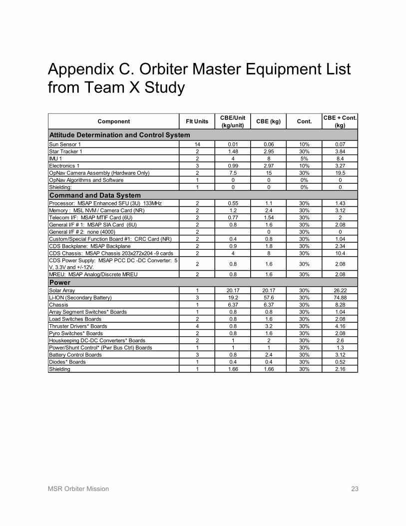
Appendix C provides the master equipment list (MEL) for the proposed orbiter.
EEV
Orbiting Sample (OS) container with battery operated UHF low-duty cycle beacon (as backup)
Capture Basket concept testing on NASA C-9 zero-g aircraft
OpNav camera used for tracking, flown on MRO integrated with ST-6 Draper ISC (Inertial Stellar Compass) systems for rendezvous Early orbiter concept with EEV.
OS is transferred to EEV upon capture.
Orbiter tracks down and captures OS in 500 km circular orbit
Figure 3-2. Rendezvous and Capture System Concept

MSR Orbiter Mission 8
Earth Entry and the Earth Entry Vehicle Preliminary Design The return to Earth would be via a biased non-Earth-impact trajectory. The orbiter would target toward Earth several days prior to EEV release, nominally entry-minus-4 hours, and then divert away from Earth following EEV release. The return and entry process is modeled after the Stardust and Genesis missions that successfully landed at the UTTR. However, steps would be taken to guarantee a higher degree of reliability (such as added redundancy and cross-checking trajectory planning by multiple teams). Unlike Genesis and Stardust, the MSR EEV would also be parachute-less and self-righting (tumble-free) during atmospheric entry, eliminating these failure modes. A preliminary LaRC design reached a high degree of maturity in 2000 and still holds up to scrutiny (see [5] for details). A full-scale (0.9 m diameter) developmental model was impact tested at UTTR, dropped from high-altitude, reaching terminal velocity (Figure 3-3). In addition, wind-tunnel testing and high-fidelity simulations have been performed that show that the vehicle would right itself into a stable orientation prior to the entry heat-pulse, even if released backwards or tumbling. The heat-shield material of choice for the EEV would be carbon phenolic, with very high heritage and reliability established by the Department of Defense (DOD). The technology program would refresh the design and finish development by PDR. The EEV design would be ready for flight testing by PDR if determined necessary; however, flight testing is currently considered optional.
The EEV would be completely passive, except for self-contained range beacons that would be initiated at entry. The structure would be carbon-carbon, supporting the carbon phenolic heat shield. Titanium would be considered as an alternate structure material. The impact shield would be an energy absorber made up of cells of carbon foam with resin-impregnated Kevlar and carbon walls. The OS would fit in the center of the EEV, inside a 5 mm-thick flexible rubberized Kevlar containment vessel that would be sealed in Mars orbit before return toward Earth. Mechanical latches would be used to secure the lid (top half) of the EEV, once the OS is inserted. Table 3-3 lists the mass breakdown of the EEV design (power estimates are not applicable for this passive design).
Containment Vessel
LaRC’s chuteless EEV Concept
EEV development model dropped tested at UTTR, reached terminal velocity
Preliminary EEV Design
Figure 3-3. Earth Entry Vehicle Preliminary Design

MSR Orbiter Mission 9
Table 3-3. Earth Entry Vehicle Mass and Power Estimate Mass Average Power CBE
(kg) % Cont. MEV (kg)
CBE (W) % Cont.
MEV (W)
Structures and mechanisms 16.5 43% 23.6 - - - Thermal control 0.4 43% 0.6 - - - Thermal protection system (TPS) 15.7 43% 22.5 - - - Range beacons 0.1 43% 0.2 - - - Sensors and cables 0.3 43% 0.4 - - - Total EEV Dry Mass 33.0 43% 47.2 - - -
Mars Returned Sample Handling Concept MRSH denotes the “ground segment” of the proposed MSR mission, i.e., the activities occurring after landing of the sample return capsule on Earth. The most recent National Research Council (NRC) study, Assessment of Planetary Protection Requirements for Mars Sample Return Missions [6], as well as previous studies referenced therein, included high-level recommendations for MRSH. Discussion of the ground segment of MSR often emphasizes the planetary protection aspects, which take the form of policy. However, the ground segment represents a broad multifaceted element of MSR, and would include landing site operations, Earth surface transportation, the SRF (one or more), and curation (e.g., the formal record-keeping, storage, protection, and distribution) of the samples over time (Figure 3-4).
After landing, MSR would require that the whole EEV be put in a quarantine vault with cooling (to maintain sample integrity) as soon as possible, and be securely transported to the SRF.
The SRF represents the facility and processes that would be needed to
• Handle the samples (and vehicle) in a manner as if they are potentially hazardous materials
• Keep the samples isolated from Earth-borne contaminants
• Apply a rigorous protocol to determine if there is any hazard in potentially releasing samples to other laboratories outside the facility
The NASA Planetary Protection Officer commissioned the development of a draft test protocol that would represent one “necessary and sufficient” approach to evaluate the safety of the samples while safeguarding the purity of the samples from terrestrial contamination. A Draft Test Protocol for Detecting Possible Biohazards in Martian Samples Returned to Earth was published in October 2002 [7]. In 2003, three architectural design teams independently examined the scope, approach, cost, and technology required for the SRF, using the Draft Test Protocol for requirements. The approaches varied from all-robotic handling of samples to more traditional glove box implementations. The studies indicated that the principles and techniques required are generally mature. Biosafety laboratories, the NASA Lunar Sample Facility, pharmaceutical laboratories, and electronic fabrication cleanrooms perform most of the required individual functions. However, there are some areas needing early development, such as ensuring sample preservation and bio-safety together, representing new challenges that were addressed by techniques like dual-walled containers (and gloves) with positive pressure clean inert gas in between the walls. This, as well as some further development in ultra-clean sample manipulation, safe and pure transport of samples, and sample sterilization techniques, are planned in the technology program.
Future studies would explore the possibility of implementing an SRF at or adjacent to an existing BSL-4 facility since containment at BSL 4 is consistent with MSR’s containment requirements. However, BSL facilities do not have and do not meet science contamination requirements that would be imposed on a sample returned from Mars. For that reason, MSR mission cost estimates assume the development of a new facility. In addition, if MSR becomes an international program, there likely would be interest in more than one SRF.

MSR Orbiter Mission 10
Landing of sample in Earth Entry Vehicle
(location TBD)
Sample Receiving Facility• Quarantine & isolate from
terrestrial contamination• Perform biohazard testing• Acquire safety certification
Location TBD
SRF
Sample Curation Facility• Protect and preserve• Distribute and control
Samples transferred only if release criteria are met
NASA CentersNational LabsUniversities
Sample Assessment in SRF• Extant life determination• Toxicity determination• Other science if samples do
not meet release criteria
Distributed Science • Extinct life detection• Geological interpretation• Materials characterization• Ground-truth for Mars
missions
Ground Recovery
Operations
Location TBDSCF
Figure 3-4. Mars Returned Sample Handling Concept If the samples are certified non-hazardous, they could be transferred to a curation facility (potentially at NASA-JSC in association with the established Astromaterials Curation Laboratory). Project costs assume nominal development of this laboratory. Curation functions would include long-term pristine sample storage, sample processing, and controlled distribution to outside investigators potentially around the world. As continues today with the Apollo lunar samples, the Martian samples would be amongst the most carefully studied materials in history, not only by biologists, but also by geologists, geochemists, and atmospheric scientists. While the estimated cost for a nominal facility is included in MRSH, the ongoing decades of curation and controlled distribution is outside the scope of this study.
A comprehensive overview of the SRF design studies, including cost and background, can be found in [8], attached as Appendix D.
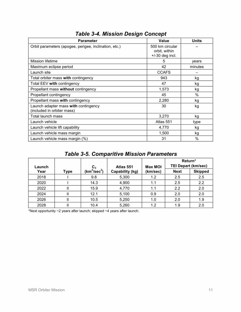
Concept of Operations and Mission Design The sequence of operations in the proposed Orbiter Mission has been discussed throughout this report. Table 3-4 provides the mission and system parameters for the mission preliminarily planned for 2022.
To be conservative, the use of the Atlas-551 has been used for costing; however, the mission would likely be able to use an Atlas with fewer strap-on solid rockets motors.
This proposed mission is preliminarily planned for launch in 2022. The parameters in Table 3-4 reflect that opportunity. Table 3-5 compares mission parameters with the 2022 performance enveloping the performance challenges for the rest of the decade. The skipped opportunity listed for TEI is for the baseline of sending the orbiter first and the lander in the second opportunity, and returning in roughly the third opportunity (see Figure 3-5).
The baseline mission sequence would send the orbiter in 2022 and the lander in 2024, with return in 2026. Return to Earth would take ~9 months for most opportunities, but returning in 2022 through 2026 would have the arrival of the EEV in Earth’s southern hemisphere, and would require a 6-month swingby to reach a northern hemisphere landing site such as UTTR.
MSR Orbiter Mission 11
Table 3-4. Mission Design Concept Parameter Value Units
Orbit parameters (apogee, perigee, inclination, etc.) 500 km circular orbit, within
+/-30 deg incl.
–
Mission lifetime 5 years Maximum eclipse period 42 minutes Launch site CCAFS – Total orbiter mass with contingency 943 kg Total EEV with contingency 47 kg Propellant mass without contingency 1,573 kg Propellant contingency 45 % Propellant mass with contingency 2,280 kg Launch adapter mass with contingency (included in orbiter mass)
30 kg
Total launch mass 3,270 kg Launch vehicle Atlas 551 type Launch vehicle lift capability 4,770 kg Launch vehicle mass margin 1,500 kg Launch vehicle mass margin (%) 31 %
Table 3-5. Comparitive Mission Parameters
Launch Year Type
C3 (km2/sec2)
Atlas 551 Capability (kg)
Max MOI (km/sec)
Return* TEI Depart (km/sec)
Next Skipped 2018 I 9.8 5,300 1.2 2.5 2.5 2020 I 14.3 4,900 1.1 2.5 2.2 2022 II 15.9 4,770 1.1 2.2 2.0 2024 II 12.1 5,100 0.9 2.0 2.0 2026 II 10.5 5,250 1.0 2.0 1.9 2028 II 10.4 5,260 1.2 1.9 2.0
*Next opportunity ~2 years after launch; skipped ~4 years after launch.

MSR Orbiter Mission 12
CY-1 CY-3 CY-4 CY-5
LANDER
ORBITER
OS Detect & RendEDL Coverage
MA
V L
au
nc
h
Rover Ops
Orbiter Launch
Lander Launch
Earth Landing
Mars Orbit Insertion (MOI)
Trans- Earth Injection (TEI)
Extended Surface Ops
Aerobraking
to 500km
CY-2
Figure 3-5. Generic Mission Timeline
For this proposed Orbiter Mission, launch is scheduled for 9/2022, arriving at Mars in 8/2023, leaving Mars in 8/2026, and landing on Earth in 12/2027 (which would include the 6-month swingby to be able to land in the northern hemisphere). The launch window is assumed to be the traditional 20 days for Mars missions.
Communications for the proposed Orbiter Mission would be through the Deep Space Network (DSN). Table 3-6 summarizes the need for coverage, consistent with previous Mars orbiters. Note that without science instruments, the data volume would be low, so X-Band would be adequate. The Decadal Survey guidelines indicate that Ka-Band should be used post 2018. It is believed that X-band might still be available; however, Ka-Band could be used, with a cost of $5M–$10M and insignificant impact on mass and volume.
Table 3-6. Mission Operations and Ground Data Systems
Downlink Information Nominal Phases Rendezvous Aerobraking Maneuvers
Number of contacts per week 7 Continuous 14–21 Continuous
Number of weeks for mission phase, weeks
Throughout 3 weeks 9 months 6 days each x 12
Downlink frequency band, GHz – 8.4 GHz X-Band X-Band X-Band X-Band
Telemetry data rate(s), kbps 10 kbps 10 kbps 10 kbps 10 kbps
Transmitting antenna type(s) and gain(s), DBi
1.0 m HGA 1.0 m HGA 1.0 m HGA 1.0 m HGA
Transmitter peak power, watts
Downlink receiving antenna gain, DBi 34 m DSN 34 m DSN 34 m DSN 34 m DSN
Transmitting power amplifier output, watts 17 watts 17 watts 17 watts 17 watts
Total daily data volume, (MB/day) 170 Mb 170 Mb 170 Mb 170 Mb
Uplink Information
Number of uplinks per day 1 per day Several Several Several
Uplink frequency band, GHz – 7.2 GHz X-Band X-Band X-Band X-Band
Telecommand data rate, kbps 2 kbps 2 kbps 2 kbps 2 kbps
Receiving antenna type(s) and gain(s), DBi
1.0 m HGA 1.0 m HGA 1.0 m HGA 1.0 m HGA

MSR Orbiter Mission 13
Planetary Protection The orbiter must meet the requirements for Category III (forward planetary protection). This level of requirements has been implemented in all past Mars orbiters, with procedures like trajectory biasing, analysis, and selected bake-out of subsystems, all included in the cost.
The main challenge for the proposed Orbiter Mission would be to meet the BPP requirements of Category V, restricted Earth return. Preventing contamination of Earth by potentially bio-hazardous Martian material would require highly reliable sample containment and ultra-safe entry and landing on Earth, as well as breaking-the-chain-of-contact with Mars in a way that would preclude return of Mars organisms outside of the sample containment. The current MSR architecture and plans reflect these implementation features, and the MSR technology program includes continued development of capabilities not yet fully demonstrated as outlined in the Technology Development Plan section. A PRA has been used to guide selection of techniques and will continue to be updated as trades and technology alternate paths are selected.
Breaking-the-chain-of-contact has several features to it, including ensuring that the samples would be sealed in a reliable container. Nominally, the OS would be sealed into a container that would be brazed shut at the orbiter. In addition, there cannot be any Mars organisms outside the sealed container that could return to Earth. This could be implemented by minimizing Mars dust transfer from the MAV by keeping it in a non-contaminated cocoon, shedding atmospheric dust during launch, and allowing time for the OS to be in free-space before contact with the orbiter. The equipment deck of all the capture and transfer hardware could be ejected prior to leaving Mars if analysis determines it necessary. The EEV would be in a biobarrier, which would also provide micrometeoroid protection. A belt-and-suspenders approach is planned, diverting the orbiter into a non-Earth impact trajectory and designing the EEV so that all external surfaces reach sterilization temperatures upon entry.
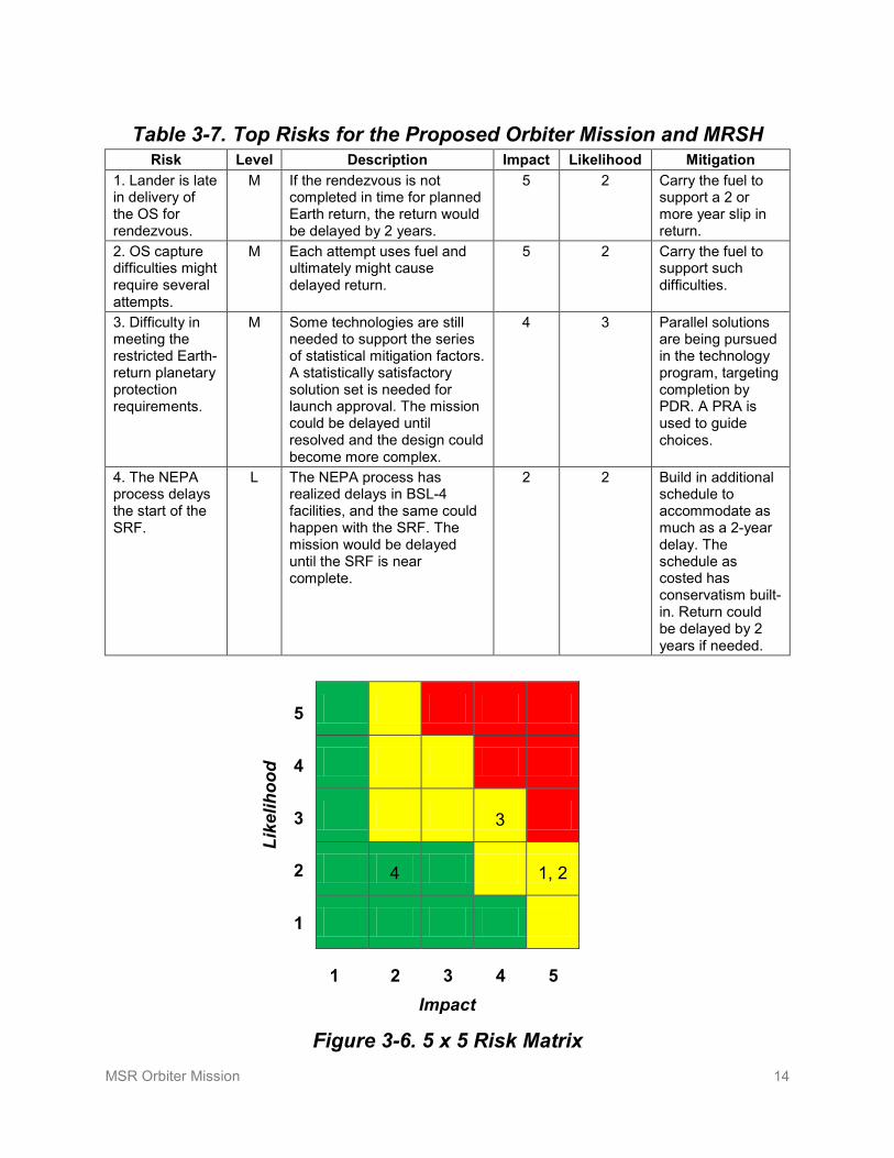
Risk List Table 3-7 lists the top mission and implementation risks for the proposed Orbiter Mission and MRSH. Figure 3-6 correlates the likelihood and impact on a 5x5 risk matrix (with risk level color coding of green = low, yellow = medium, and red = high). Table 3-8 is a key to risk assessment.
MSR Orbiter Mission 14
Table 3-7. Top Risks for the Proposed Orbiter Mission and MRSH Risk Level Description Impact Likelihood Mitigation
1. Lander is late in delivery of the OS for rendezvous.
M If the rendezvous is not completed in time for planned Earth return, the return would be delayed by 2 years.
5 2 Carry the fuel to support a 2 or more year slip in return.
2. OS capture difficulties might require several attempts.
M Each attempt uses fuel and ultimately might cause delayed return.
5 2 Carry the fuel to support such difficulties.
3. Difficulty in meeting the restricted Earth-return planetary protection requirements.
M Some technologies are still needed to support the series of statistical mitigation factors. A statistically satisfactory solution set is needed for launch approval. The mission could be delayed until resolved and the design could become more complex.
4 3 Parallel solutions are being pursued in the technology program, targeting completion by PDR. A PRA is used to guide choices.
4. The NEPA process delays the start of the SRF.
L The NEPA process has realized delays in BSL-4 facilities, and the same could happen with the SRF. The mission would be delayed until the SRF is near complete.
2 2 Build in additional schedule to accommodate as much as a 2-year delay. The schedule as costed has conservatism built-in. Return could be delayed by 2 years if needed.
3
4 1, 2
Figure 3-6. 5 x 5 Risk Matrix
Like
lihoo
d
1 2 3 4 5 Impact
5
4
3
2
1

MSR Orbiter Mission 15
Table 3-8. Risk Level Definitions
Levels Mission Risk Implementation Risk
Impact Likelihood of Occurrence Impact Likelihood of
Occurrence
5
Mission failure Very high, ~10%
Consequence or occurrence is not repairable without engineering (would require >100% of margin)
Very high, ~70%
4
Significant reduction in mission return (~10% of mission return still available)
High, ~5% All engineering resources will be consumed (100% of margin consumed)
High, ~50%
3
Moderate reduction in mission return (~50% of mission return still available)
Moderate, ~1% Significant consumption of engineering resources (~50% of margin consumed)
Moderate, ~30%
2
Small reduction in mission return (~90% of mission return still available)
Low, ~0.5% Small consumption of engineering resources (~10% of margin consumed)
Low, ~10%
1
Minimal (or no) impact to mission (~99% of mission return still available)
Very low, ~0.1%
Minimal consumption of engineering resources (~1% of margin consumed)
Very low, ~1%

MSR Orbiter Mission 16
4. Development Schedule and Schedule Constraints
High-Level Mission Schedule Figure 4-1 shows the development schedule for the proposed Orbiter Mission (planned for launch in 2022) and the proposed SRF, which is the core of MRSH. It also shows an early NEPA process (with Notice of Intent [NOI] milestones) necessary to ensure adequate time to support return of samples in 2027. Table 4-1 lists the duration of key phases of proposed Orbiter Mission development.
Figure 4-1. Development Schedule for the Proposed Orbiter Mission and MRSH
Table 4-1. Proposed Key Phase Duration Project Phase Duration (Months)
Phase A – Conceptual Design 17 months Phase B – Preliminary Design 10 months Phase C – Detailed Design 22 months Phase D – Integration & Test 18 months Phase E – Primary Mission Operations 63 months Phase F – Extended Mission Operations None Start of Phase B to PDR 8 months Start of Phase B to CDR 20 months Project total funded schedule reserve Built in to schedule (~1 month/year) Total development time Phase B–D 50 months

MSR Orbiter Mission 17
Technology Development Plan Three areas require technology development: 1) rendezvous and capture, 2) BPP, including the EEV, and 3) technologies for handling samples in the SRF.
All three areas will be developed over about a 4-year period leading to TRL 6 by PDR as indicated in the development schedule above. The cost for technology development is included and identified as a line item in the overall mission and MRSH costs listed in Table 5-1.
Rendezvous and Capture The following tasks are planned:
• Combine a version of the OpNav camera flying on MRO with a ST-6 Draper ISC package for a complete autonav system.
• Select and integrate autonav algorithms proven on Orbital Express, DS-1, and Deep Impact.
• Develop a simple light source for proximity operation during eclipse.
• Develop a UHF beacon and power source for the OS (bird collar and solar cell hardware)
• Perform further refinement, trades, and testing of the capture system.
• Integrate hardware in the loop testing.
Except for the UHF beacon, enough work has been done to lend confidence that the tasks would be successful. The beacon for the OS is optional, but would provide some measure of backup in locating the OS. It would not be enabling.
Back Planetary Protection BPP would require a complex and many-faceted approach and an end-to-end solution to meet the stringent restricted-Earth-return planetary protection requirements. .Systems engineering and PRA analysis would overlay these activities to provide the proper guidance and decision-making process that would lead to successfully development.
Specific tasks preliminarily planned (plan will be kept flexible) are:
• Develop sealing techniques for the OS. Explosive welding and brazing have been demonstrated at TRL 3–4. This work needs to continue and be down-selected within the first 2 years.
• Study and develop dust mitigation techniques. There are several techniques available, but analysis still needs to be performed to down-select.
• Develop a leak detection (preferably wireless) technique to ensure that the OS is not compromised. Preliminary proof of concept has demonstrated via a Small Business Innovation Research (SBIR) task in 2005.
• Select materials for the OS, CV, and EEV to ensure meteoroid protection (and landing protection) with high probability. Initial considerations are aluminum with high-density foam OS, rubberized-Kevlar “bag” CV, high density foams, and removable EEV meteoroid shields. In addition, detection of shield penetration could be used. Multiple solutions are available, but they need to be developed far enough in the first 1.5 years to be down-selected for further testing. Hyper-velocity testing of the Kevlar CV materials have been performed in the past but stopped prematurely due to loss of funding.
• Refresh the EEV design, test existing TPS, and put developmental models through a variety of testing by PDR.
MSR Orbiter Mission 18
Mars Returned Sample Handling The main challenge for MRSH would be sample cleanliness while ensuring containment. A few areas need more development—double-walled containment vessels, rapid transfer ports, and double-walled gloves. In addition, robotics for sample manipulation and common carriers need to be developed. While these areas are not new to industry, they need tailoring to meet MRSH purposes. In addition, sterilization techniques need to be further studied and developed.
Development Schedule and Constraints There is nothing unusual about the proposed Orbiter Mission that would indicate schedule issues at this point of planning. Care has been taken to adequately plan technologies and advanced development (i.e., with the EEV) to be completed prior to PDR.
Launch opportunities occur roughly every 26 months; thus, if the spacecraft was not ready for launch, a 2-year slip would occur.

MSR Orbiter Mission 19
5. Mission Life-Cycle Cost Costing Methodology and Basis of Estimate The proposed Orbiter Mission design and cost is provided by JPL’s Team X using their quasi-grassroots process. Combinations of grassroots, parametric analysis, and analogy models are used by each of the discipline chairs representing their implementing organizations. These models have been validated against actual costs of prior JPL missions.
The Team X study was performed in October 2009. Costs have been modified to meet the Decadal Survey guidelines of 50% reserves for development (Phases A–D) and 25% for operations (Phase E).
The EEV costs dates back to 2002, when NASA LaRC last completed a grassroots cost estimate based on their mature concept.
All cost have been inflated to fiscal year (FY) 2015 dollars as requested by the Decadal Survey.
Launch vehicle cost is as specified in the Decadal Survey ground rules for mission studies.
MRSH cost estimates have 50% reserves, and are based on results of industry studies (described in Appendix D).
Technology development costs are based on estimates from the potential implementing organizations at JPL and other NASA centers, and have 50% reserves.
Cost Estimates Table 5-1 summarizes the total mission costs for the proposed Orbiter Mission, and the cost estimate for MRSH through two years of operations for testing the sample before potential release.

MSR Orbiter Mission 20
Table 5-1. Total Estimated Mission Cost Funding Profile (FY Costs in Real Year Dollars, Totals in Real Year and 2015 Dollars)
FY 2016 2017 2018 2019 2020 2021 2022 2023 2024 2025 2026 2027 2028 2029 Total RY
Total FY15
ORBITER MISSION
Pre-Phase A 10 10 20 21
Technology Development 20 47 58 32 157 149
Development A–D
Mission PM/SE/MA 1 6 19 27 27 27 107 92
EEV 2 6 9 9 9 35 30
Orbiter 5 27 62 92 100 90 376 325
MSI&T 1 5 15 16 17 54 46 Ground Data System Dev 1 3 4 4 4 16 16
Mission Design 1 4 6 6 6 23 19
Total A–D w/o Reserves 6 38 99 153 162 153 611 531
A–D Reserves 3 19 50 77 81 77 307 265
Total A–D Cost 9 57 149 230 243 230 918 796
Launch Services 100 129 70 299 257
Phase E Costs 16 16 17 18 13 80 62
Phase E Reserves 4 4 4 5 3 20 15
Total Phase E 20 20 21 23 16 100 77
DSN 1 1 1 9 10 10 10 8 50 36
Education/Outreach 1 1 1 1 1 1 1 1 8 7
Total Mission Costs 30 66 115 181 332 374 302 30 31 32 34 25 1552 1343
MRSH
Technology Development 5 10 12 8 35 33
MRSH Dev & Operations 4 10 12 27 12 218 22 65 38 32 33 32 22 10 537 438
Total MRSH 9 20 24 35 12 218 22 65 38 32 33 32 22 10 572 471
Notes: MSI&T—Mission System Integration and Test and preparation for operations. Includes all costs to NASA including estimated DSN costs.

MSR Orbiter Mission 21
Appendix A. Acronyms BOL beginning of life
BPP back planetary protection
BSL bio-safety level
CBE current best estimate
CML concept maturity level
DARPA Defense Advanced Research Projects Agency
DOD Department of Defense
DOE Department of Energy
DSN Deep Space Network
EDL entry/descent/landing
EEV Earth entry vehicle
EOL end of life
ESA European Space Agency
FY fiscal year
HGA high gain antenna
ISC Inertial Stellar Compass
JSC Johnson Space Center
KSC Kennedy Space Center
LaRC Langley Research Center
MAV Mars ascent vehicle
MEL master equipment list
MEV maximum expected value
MOI Mars Orbit Insertion
MRSH Mars Returned Sample Handling
MSR Mars Sample Return
NEPA National Environmental Policy Act
OS orbiting sample
PDR Preliminary Design Review
PRA probabilistic risk assessment
RCS reaction control system
RY real year
SBIR Small Business Innovation Research
SEP solar electric propulsion
SRF sample receiving facility
TEI Trans-Earth Injection
TRL technology readiness level
UHF ultra-high frequency
UTTR Utah Test and Training Range

MSR Orbiter Mission 22
Appendix B. References [1] National Aeronautics and Space Administration. March 2010. Mission Concept Study: Planetary
Science Decadal Survey—Mars 2018 MAX-C Caching Rover.
[2] National Aeronautics and Space Administration. Mission Concept Study: Planetary Science Decadal Survey—MSR Lander Mission. In review.
[3] Friend, R. 15 April 2008. “Orbital Express Program Summary and Mission Overview,” Proc. SPIE 6958, 695803.
[4] Kornfeld, R., Parrish, J., and Sell, S. May–June 2007. “Mars Sample Return: Testing the Last Meter of Rendezvous and Sample Capture,” Journal of Spacecraft and Rockets 44(3).
[5] Dillman, R., Laub, B., Kellas, S., and Schoenenberger, M. “Development and Test Plans for the MSR EEV,” 2nd International Planetary Probe Workshop, August 2004.
[6] National Research Council. 2009. Assessment of Planetary Protection Requirements for Mars Sample Return Missions.
[7] Rummel, J.D. et al., eds. 2002. A Draft Test Protocol for Detecting Possible Biohazards in Martian Samples Returned to Earth, NASA/CP-2002-211842, National Aeronautics and Space Administration, Washington, DC.
[8] Beaty, D., et al. 2009. “Planning Considerations for a Mars Sample Receiving Facility: Summary and Interpretation of Three Design Studies,” Astrobiology 9(8): 745–758, 2009, Mary Ann Liebert, Inc., publishers, www.liebertpub.com/ast.
MSR Orbiter Mission 23
Appendix C. Orbiter Master Equipment List from Team X Study
Component Flt Units CBE/Unit (kg/unit) CBE (kg) Cont. CBE + Cont.
(kg)
Sun Sensor 1 14 0.01 0.06 10% 0.07Star Tracker 1 2 1.48 2.95 30% 3.84IMU 1 2 4 8 5% 8.4Electronics 1 3 0.99 2.97 10% 3.27OpNav Camera Assembly (Hardware Only) 2 7.5 15 30% 19.5OpNav Algorithms and Software 1 0 0 0% 0Shielding: 1 0 0 0% 0
Processor: MSAP Enhanced SFU (3U) 133MHz 2 0.55 1.1 30% 1.43Memory : MSL NVM / Camera Card (NR) 2 1.2 2.4 30% 3.12Telecom I/F: MSAP MTIF Card (6U) 2 0.77 1.54 30% 2General I/F # 1: MSAP SIA Card (6U) 2 0.8 1.6 30% 2.08General I/F # 2: none (4000) 2 0 30% 0Custom/Special Function Board #1: CRC Card (NR) 2 0.4 0.8 30% 1.04CDS Backplane: MSAP Backplane 2 0.9 1.8 30% 2.34CDS Chassis: MSAP Chassis 203x272x204 -9 cards 2 4 8 30% 10.4CDS Power Supply: MSAP PCC DC -DC Converter: 5 V, 3.3V and +/-12V. 2 0.8 1.6 30% 2.08
MREU: MSAP Analog/Discrete MREU 2 0.8 1.6 30% 2.08
Solar Array 1 20.17 20.17 30% 26.22Li-ION (Secondary Battery) 3 19.2 57.6 30% 74.88Chassis 1 6.37 6.37 30% 8.28Array Segment Switches* Boards 1 0.8 0.8 30% 1.04Load Switches Boards 2 0.8 1.6 30% 2.08Thruster Drivers* Boards 4 0.8 3.2 30% 4.16Pyro Switches* Boards 2 0.8 1.6 30% 2.08Houskeeping DC-DC Converters* Boards 2 1 2 30% 2.6Power/Shunt Control* (Pwr Bus Ctrl) Boards 1 1 1 30% 1.3Battery Control Boards 3 0.8 2.4 30% 3.12Diodes* Boards 1 0.4 0.4 30% 0.52Shielding 1 1.66 1.66 30% 2.16
Attitude Determination and Control System
Command and Data System
Power

MSR Orbiter Mission 24
Component Flt Units CBE/Unit (kg/unit) CBE (kg) Cont. CBE + Cont.
(kg)
Gas Service Valve 4 0.23 0.92 2% 0.94HP Latch Valve 6 0.35 2.1 2% 2.14Solenoid Valve 4 0.35 1.4 2% 1.43HP Transducer 2 0.27 0.54 2% 0.55Gas Filter 2 0.11 0.22 2% 0.22Temp. Sensor 4 0.01 0.04 2% 0.04Liq. Service Valve 2 0.28 0.56 2% 0.57Test Service Valve 2 0.23 0.46 2% 0.47LP Transducer 8 0.27 2.16 2% 2.2Liq. Filter 2 0.72 1.44 2% 1.47LP Latch Valve 8 0.35 2.8 2% 2.86Temp. Sensor 20 0.01 0.2 2% 0.2Lines, Fittings, Misc. 1 3.6 3.6 50% 5.4DM Monoprop Thrusters 2 16 0.17 2.72 10% 2.99Biprop Main Engine 4 8.65 34.58 20% 41.5Fuel Pressurant Tank 1 8.99 8.99 30% 11.68Ox Pressurant Tank 1 6.52 6.52 30% 8.48Fuel Tanks 2 18.94 37.88 30% 49.25Oxidizer Tanks 1 30.39 30.39 30% 39.51
Primary Structure 1 145.7 145.7 30% 189.41Secondary Structure 1 19.1 19.1 30% 24.83Solar Array Drive Assemblies 1 4.7 4.7 30% 6.11Solar Array Latch/Release + Booms 1 2.5 2.5 30% 3.25Antenna Gimbal Assemblies 1 6.7 6.7 30% 8.71Sample Capture and Transfer (Struc & Mech) 1 67 67 30% 87.1Aerobraking Panel 1 8.6 8.6 30% 11.18Balance Mass 1 6.59 6.59 30% 8.57Cabling Harness 1 32.97 32.97 30% 42.86Adapter, Spacecraft side 1 22.57 22.57 30% 29.34
X/X-HGA 1.0m diam Parabolic 1 1.8 1.8 20% 2.16X-LGA (8dB) Cassini 2 0.2 0.4 20% 0.48UHF-LGA MSL Helix 1 0.56 0.56 10% 0.62SDST X-up/X down 2 2.7 5.4 10% 5.94Electra 2 5.1 10.2 10% 11.22X-band SSPA, RF=15W* 2 1.5 3 10% 3.3X-band Diplexer, high isolation 2 0.8 1.6 10% 1.76Waveguide Transfer Switch (WGTS) 2 0.38 0.76 10% 0.84Coax Transfer Switch (CXS) 3 0.13 0.39 10% 0.43Hybrid Coupler 1 0.02 0.02 10% 0.02X-band Rotary Joint 2 0.25 0.5 10% 0.55Filter, low power 1 0.2 0.2 20% 0.24Coax Cable, flex (190) 8 0.16 1.31 25% 1.64WR-112 WG, rigid (Al) 6 0.43 2.58 25% 3.23Coax Cable, flex (120) 5 0.09 0.42 25% 0.53
Structures
Telecomm
Propulsion
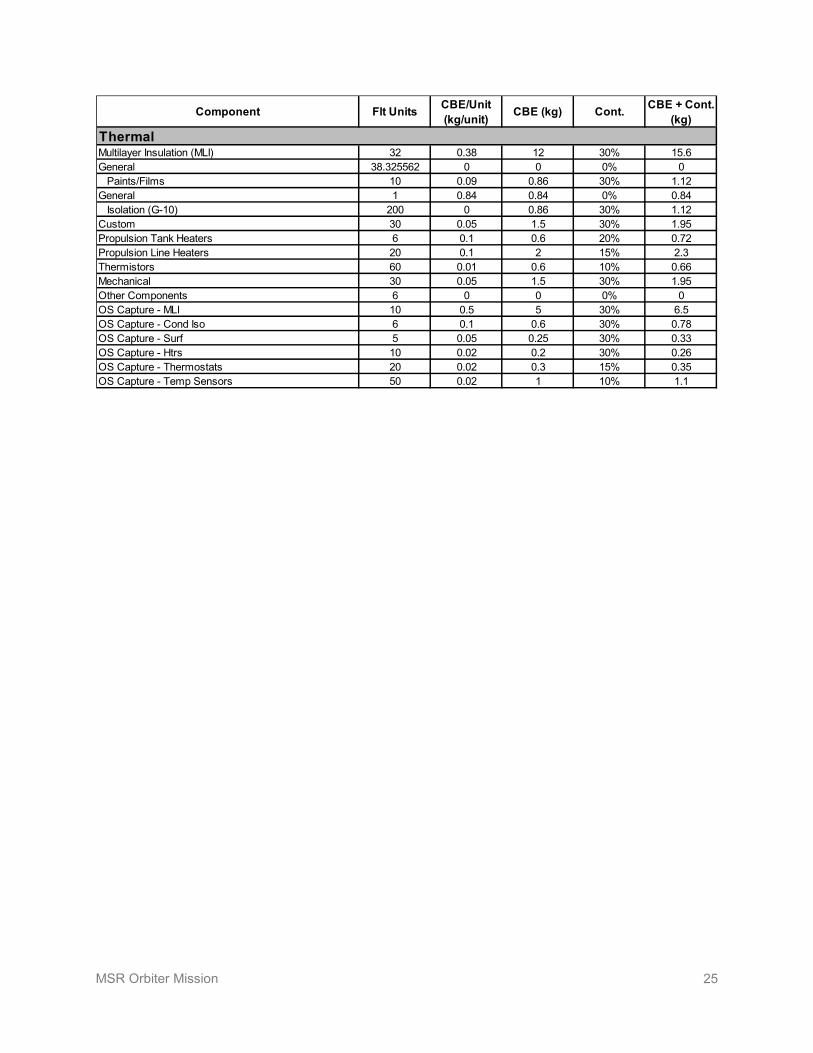
MSR Orbiter Mission 25
Component Flt Units CBE/Unit (kg/unit) CBE (kg) Cont. CBE + Cont.
(kg)
Multilayer Insulation (MLI) 32 0.38 12 30% 15.6General 38.325562 0 0 0% 0 Paints/Films 10 0.09 0.86 30% 1.12General 1 0.84 0.84 0% 0.84 Isolation (G-10) 200 0 0.86 30% 1.12Custom 30 0.05 1.5 30% 1.95Propulsion Tank Heaters 6 0.1 0.6 20% 0.72Propulsion Line Heaters 20 0.1 2 15% 2.3Thermistors 60 0.01 0.6 10% 0.66Mechanical 30 0.05 1.5 30% 1.95Other Components 6 0 0 0% 0OS Capture - MLI 10 0.5 5 30% 6.5OS Capture - Cond Iso 6 0.1 0.6 30% 0.78OS Capture - Surf 5 0.05 0.25 30% 0.33OS Capture - Htrs 10 0.02 0.2 30% 0.26OS Capture - Thermostats 20 0.02 0.3 15% 0.35OS Capture - Temp Sensors 50 0.02 1 10% 1.1
Thermal

MSR Orbiter Mission 26
Appendix D. Sample Receiving Facility Planning Article The following article “Planning Considerations for a Mars Sample Receiving Facility: Summary and Interpretation of Three Design Studies” provides a comprehensive overview of the SRF design studies, including cost and background.
Reprinted with permission from Beaty et al., “Planning Considerations for a Mars Sample Receiving Facility: Summary and Interpretation of Three Design Studies,” Astrobiology 9(8): 745–758, 2009, Mary Ann Liebert, Inc., publishers, www.liebertpub.com/ast.
Research Article
Planning Considerations for a Mars SampleReceiving Facility: Summary and Interpretation
of Three Design Studies
David W. Beaty,1 Carlton C. Allen,2 Deborah S. Bass,1 Karen L. Buxbaum,1 James K. Campbell,1,*
David J. Lindstrom,3 Sylvia L. Miller,1,* and Dimitri A. Papanastassiou4
Abstract
It has been widely understood for many years that an essential component of a Mars Sample Return mission is aSample Receiving Facility (SRF). The purpose of such a facility would be to take delivery of the flight hardwarethat lands on Earth, open the spacecraft and extract the sample container and samples, and conduct an agreed-upon test protocol, while ensuring strict containment and contamination control of the samples while in the SRF.Any samples that are found to be non-hazardous (or are rendered non-hazardous by sterilization) would then betransferred to long-term curation. Although the general concept of an SRF is relatively straightforward, there hasbeen considerable discussion about implementation planning.
The Mars Exploration Program carried out an analysis of the attributes of an SRF to establish its scope,including minimum size and functionality, budgetary requirements (capital cost, operating costs, cost profile),and development schedule. The approach was to arrange for three independent design studies, each led by anarchitectural design firm, and compare the results. While there were many design elements in common iden-tified by each study team, there were significant differences in the way human operators were to interact withthe systems. In aggregate, the design studies provided insight into the attributes of a future SRF and the complexfactors to consider for future programmatic planning. Key Words: Mars—Sample Receiving Facility (SRF)—Mars Sample Return (MSR)—Curation—Biosafety—Test protocol—Sample preservation—Containment—Cleanroom—NASA—Planetary protection. Astrobiology 9, 745–758.
1. Introduction
Arobotic mission to collect samples of Mars and trans-port them to Earth has been considered in one form or
another for more than three decades (e.g., NRC, 1978, 1990a,1990b, 1994, 1996, 2002, 2007; MEPAG ND-SAG, 2008, andreferences therein). Although different variants of this missionover the years have taken different names, we refer to themission described in this paper as Mars Sample Return, orMSR. In an engineering sense, MSR as a flight mission is oneof the most complex undertakings NASA and its Europeanpartners have ever considered—there are some fascinatingchallenges related to the flight system (see, e.g., Bar-Cohenet al., 2005; Gershman et al., 2005; Mattingly et al., 2005; Ste-phenson and Willenberg, 2006; iMARS, 2008; Moura et al.,2008; Backes et al., 2009). In addition to the complexities of the
flight system, the planning for management of the samplesonce they arrive on Earth is equally critical. Perhaps the mostimportant single element of the ‘‘ground system’’ is a facilityreferred to as the Sample Receiving Facility (SRF), whosepurpose would be to receive the returned spacecraft, extractthe sealed sample container, open it to access the samples, andthen carry out a set of tests under strict containment condi-tions to determine whether the samples are hazardous.
The SRF element of the overall mission is mandatory be-cause of international planetary protection agreements (see,e.g., Atlas, 2008; COSPAR, 2008). The NRC (1997) pointedout that, though the probability of extant martian life in sucha returned sample is very low, it is nonzero. Because of this, asample returned from Mars would be subject to the veryrigorous rules and practices in place to protect Earth from thepotential risk of extraterrestrial life. The interested reader can
1Mars Program Office, and 4Science Division, Jet Propulsion Laboratory, California Institute of Technology, Pasadena, California.2NASA Johnson Space Center, Houston, Texas.3NASA Headquarters, Washington, DC.*Retired, Mars Program Office, Jet Propulsion Laboratory, California Institute of Technology, Pasadena, California.
ASTROBIOLOGYVolume 9, Number 8, 2009ª Mary Ann Liebert, Inc.DOI: 10.1089=ast.2009.0339
745

refer to the specifics of these policies at COSPAR (2008) andMEPAG ND-SAG (2005, 2008). Although the purpose of thepolicy is clear, there has been considerable debate about thenature of the facility required to implement it.
The purpose of this paper is to summarize a set of studiesthat were undertaken in 2003 to help constrain the minimumfacility for policy compliance, with a specific goal of definingits probable basic attributes and estimating its cost. AlthoughMSR is not currently approved by any of the internationalspace agencies, this information will be needed prior toplanning the budget and timeline for the SRF should MSRproceed in the future.
1.A. History and context
The first in-depth discussion of facility planning for anMSR-related SRF was carried out in connection with planningfor the MSR 2003–2005 Project. The term ‘‘Mars ReceivingFacility’’ was introduced at the Mars Sample Handling,Distribution, and Analysis Workshop (D. McCleese and M.Drake, Chairs), which was held at Caltech in February 1999.This facility concept was renamed later that year, however,to the more generic ‘‘Sample Receiving Facility’’ (or SRF) byNASA’s newly formed Mars Returned Sample Handlingteam because of the possibility that such a facility might beused in the future for samples originating from planetaryobjects other than Mars.
Reports from studies and workshops during the decadeleading up to the 2003–2005 MSR effort established the contextfor SRF design and implementation. In 1995, NASA asked theNational Research Council (NRC) to conduct a study per-taining to sample return and address the key issues1 associ-ated with the potential risks to Earth of samples returned fromSolar System bodies, such as Mars. The NRC panel focusedprincipally on Mars and produced a report (NRC, 1997) thatbecame a cornerstone for much of the planetary protection–related work of the MSR 2003–2005 Project. In addition, theNASA Mars Sample Handling and Requirements Panel(MSHARP) made recommendations (Carr et al., 1999) re-garding what is required to certify returned samples as non-hazardous and the considerations associated with samplereceiving, curation, and distribution. MSHARP recommendedthat the samples be treated as hazardous until proven other-wise, consistent with the NRC (1997).
Because the earlier reports provided advice at a fairlygeneral level, the NRC followed up with a study of the cri-teria for release of samples from biocontainment in an SRF(NRC, 2002). Of relevance to the present study, the reportrecommended that only the most basic operations should beconducted inside the facility, and it should be designed to thesmallest and simplest possible scale consistent with its dual
roles as a biological containment and clean-room facility,with detailed protocols and procedures for handling andtesting martian samples. This report additionally argued thatit would take at least 7 years in advance of the anticipatedreturn of martian samples to plan and construct an SRF.
Beginning in 1997, NASA sponsored a series of workshops(e.g., DeVincenzi et al., 1999; Race and Rummel, 2000; Raceet al., 2001a, 2001b) to prepare a first draft of the test protocolthat would evaluate the safety of returned martian samples.The overall objective was ‘‘to produce a draft protocol bywhich returned martian sample materials could be assessedfor biological hazards and examined for evidence of life (ex-tant or extinct), while safeguarding the purity of the samplesfrom possible terrestrial contamination.’’ The resulting DraftTest Protocol (Rummel et al., 2002) was published with theexpectation that there would be continued revisions as moreinformation became available about Mars and analyticaltechniques improved. The Draft Test Protocol is described ingreater detail below, because it served as a source of designrequirements for the SRF studies summarized here.
NASA’s MSR 2003–2005 Project advanced as far as itsPreliminary Design Review before it was cancelled in 2000(O’Neil and Cazaux, 2000). NASA recognized, however, thatif an MSR project were restarted in the future, it must includerealistic planning parameters for the SRF, including cost,schedule, and size. Therefore, planning activity for the SRFcontinued through 2004, several years beyond the cancellationof the flight mission. A major aspect of this planning was a setof three independent competed industry studies that werecarried out in 2003–2004. These studies have formed the basisfor a much clearer understanding of the possible require-ments, design, cost, timeline, and operational considerationsfor an MSR-related SRF and are the focus of this paper.
2. Methods and Conceptual Requirements
No individual facilities currently exist that meet all therequirements of the SRF (which are described in a followingsection) (see also Atlas, 2008). Moreover, there are technicalreasons related to achievement of the necessary standards ofcleanliness, which led us to conclude that it was very un-likely to achieve an acceptable SRF by modifying an existingbuilding. Thus, for the purpose of this study, we focusedonly on the planning of a new facility. This would constitutea reference point to which possible alternative options re-lated to modification of existing facilities could be comparedin the future.
In response to a NASA-originated solicitation, seven let-ters of interest were received in May 2003. Through anevaluation board, three architectural design teams were se-lected to carry out separate $200 thousand, 6-month studies.Each team had industry experts who specialize in clean-room design, biohazard considerations, aseptic processing,robotics, and advanced instrumentation. The three teamswere led by Industrial Design and Construction (IDC) ofPortland, Oregon; Lord, Aeck, Sargent (LAS) of Atlanta,Georgia; Flad & Associates (FLAD) of Madison, Wisconsin.The three industry teams operated independently and de-livered their analyses in 2004 in the form of final reports to beused by NASA for future planning.
Each of the architectural design teams was asked to con-duct a design study and also provide a cost estimate for an
1The NRC (1997) addressed the following issues: (a) the potentialand probability for a living entity to be included in a sample re-turned from another Solar System body, in particular Mars; (b) thescientific investigations that should be conducted to reduce uncer-tainty in the above assessment; (c) the potential for large-scale effectson the environment resulting from the release of any returned entity;(d) the status of technological measures that could be taken on amission to prevent the unintended release of a returned sample intoEarth’s biosphere; and (e) the criteria for controlled distribution ofsample material, taking note of the anticipated regulatory frame-work.
746 BEATY ET AL.

SRF that operates at a containment level equivalent toBiosafety Level 4 (BSL-4). For the purpose of the analysis, itwas assumed that the SRF would receive samples fromMars collected by a mission launched in 2013, with thesamples returned to Earth at the end of 2016, by which timethe SRF would have been certified to receive samples. Theteams were asked to prepare designs that would meet re-quirements for (a) ensuring containment of potential non-terrestrial biological material in the sample, (b) preventingcontamination of the sample by terrestrial contaminants(biological and inorganic materials), and (c) permitting pre-liminary examination, hazard assessment, and life-detectionanalyses of the samples.
2.A. Draft test protocol
The design teams were told that the SRF concepts mustpermit implementation of the Draft Test Protocol (Rummelet al., 2002). This document lays out an approach for returnedsamples to be subsampled and subjected to ‘‘sufficient testingto evaluate them against the release criteria.’’ The Protocolitself has three main segments: physical=chemical proces-sing, life-detection testing, and biohazard testing. In theProtocol, these tests are defined, and flow charts are used tocomplement the text in describing the conceptual flowthrough the test process. There is emphasis throughout onapproaches to sample examination that are credible, thor-ough, and informative while maintaining a priority forsample preservation—both in quantity and quality. The de-velopers of the Protocol were careful to point out that thetests must be sufficient to answer the key questions con-cerning possible life and biohazard while preserving, to thegreatest extent possible, the quantity of sample available forfuture science. Therefore, the Draft Test Protocol ‘‘attempts acompromise between the desire to destructively analyze onlya small proportion of the returned sample by planetaryprotection testing, and the need to assure safety by testing allportions of all samples.’’ All the while, the sample portionspreserved for science must remain pure (uncontaminated)and unaltered to the greatest extent possible.
2.B. Facility scope
For the purpose of the industry studies, long-term, majorscientific research in the SRF was not to be considered—either the samples meet the release criteria and are allocatedto non-containment laboratories or additional facilities at theSRF must be created. The design teams were told that SRFconcepts under consideration should represent the minimumfacility to implement the Draft Test Protocol on representa-tive samples within 6–9 months of sample receipt. To complywith the Draft Test Protocol, the teams were to assume theneed for testing on live animals (although it was recognizedthat this need might eventually be eliminated). Further, theywere to address whether it would be preferable to includethis functionality in the SRF or make use of some secondaryfacility that meets the SRF containment requirements thoughnot necessarily the sample cleanliness requirements.
The design concepts for the SRF had to provide for thefollowing:
(1) Receiving and opening the spacecraft, removing thesamples;
(2) Sample splitting and packaging as required to providesubsamples for further testing as specified in the DraftTest Protocol;
(3) The capability to sterilize subsamples for analysisoutside of containment;
(4) The sterilization of any waste products from the SRFthat might have been exposed to martian samples;
(5) The capability to prepare and package martian sam-ples that have been certified non-hazardous for trans-fer to a Mars Sample Curation Facility and distributionfor further science investigations.
2.C. Containment and sample purity
The special considerations of biocontainment, coupledwith the limited amount of precious sample and the scientificrequirements for sample purity, were fundamental to theindustry concept studies. For the purposes of the studies,contamination of returned martian samples fell into threebroad categories, based on expected and proposed areas ofscientific investigations: biological, organic, and inorganic. Inpractice, an investigation in one of these areas might not beadversely affected by contamination in a different area.However, the first-order principle was that all three cate-gories must be considered together. A report by Neal (2000)on behalf of the NASA Curation and Analysis PlanningTeam for Extraterrestrial Materials (CAPTEM) addressesthese issues in some detail. CAPTEM’s recommendations,like those of the NRC (2002), recognized a major technicalobstacle to designing the SRF: the problem of combininghigh-level biological containment with clean-room condi-tions. For example, when considering design of the con-tainment facility for potentially hazardous samples, it isexpected that samples would be stored under negative airpressure with respect to the outside laboratory to maximizebiocontainment. By contrast, non-hazardous samples thatmust be kept pristine are typically stored under positive airpressure to minimize contamination. This illustrates the un-usual requirement for an SRF to maintain both sample con-tainment and cleanliness.
A significant part of the scientific purpose of MSR wouldbe to evaluate returned martian samples for evidence ofmartian prebiotic chemistry, martian life itself, or both. SinceEarth-sourced contaminants, particularly organic molecules,can give a false-positive signal, contamination control wouldbe an essential aspect of the mission. It would be essential tosterilize and clean all elements that the samples contact be-tween their native state on Mars and their analysis in in-struments on Earth. An implication for the SRF is that theinterior of the isolator cabinets, the trays, the sample con-tainers, the sample-contact tools, and the sample chambers ofthe organic detection instruments would need to be cleanedto the same standards as for the sample-contact surfaces ofthe flight system. The standards and protocols for achievingthis would have to be established, but this was not an as-sumption or SRF requirement for the study teams.
2.D. US site selection issues
If it is decided to proceed with selection of a location for anSRF, several issues would need to be addressed. First, one oftwo general selection processes would have to be chosen:
PLANNING A MARS SRF 747

either an internal down-select process or an external nomina-tion process. The former would entail that a national agency,such as NASA, progressively narrow down on a site that meetsits needs; the latter would involve a competition among can-didate sites proposed by advocates. Although there are ad-vantages and disadvantages to each approach, it is particularlyworth noting that the competitive process would take signifi-cantly more time, and this would need to be taken into accountin the planning and possibly costing. Second, any pass=failthreshold site criteria would need to be established. Thesemight include perimeter security, government land ownership,access to transportation and utilities, avoidance of legallyprotected areas, and so on. Third, a set of evaluation criteriawould need to be established to determine relative prioritiza-tion of candidate sites that pass the threshold criteria. In the US,it is required by the National Environmental Policy Act (NEPA)that the potential environmental impacts be considered early inthe decision-making process, but other additional criteriamight include fewest land use conflicts, user accessibility andconvenience, risk due to natural hazards, and cost (includingthe cost of mitigating natural hazards). Finally, partneringoptions (of many different types) might play a significant rolein improving the cost, efficiency, or management of the SRF.For example, placing the SRF adjacent to an existing BSL-4 labmight result in certain efficiencies, and this would clearly havesite selection implications.
2.E. Costing guidelines
To prepare a cost estimate, the teams were given the fol-lowing additional assumptions:
(a) The launch of the MSR mission was to occur in No-vember 2013, and the assumed arrival of the sampleback on Earth was July 2016.
(b) Cost estimates for the analytical capabilities, both ac-quisition and implementation, had to include multi-spectral imaging, microscopy, mass comparison,radiation counting, gas chromatography–mass spec-trometry, Raman spectroscopy, X-ray diffraction, X-raytomography, X-ray fluorescence, atomic force micros-copy, and scanning electron microscopy.
(c) No land-acquisition costs were included. The site forthe SRF is treated as a vacant lot in an urban area. Thatis, roads, power, water and sewer are accessible.
(d) All tasks associated with NASA personnel were to bebudgeted separately.
(e) All costs related to the external science communitywere to be budgeted separately.
3. Existing Facility Analogues for SRF Functionalities
As discussed above, there is no single facility in the worldthat would meet all the assumed requirements of the SRF.However, there are separate important facility engineeringanalogues for most of the aspects of the SRF, and in manyrespects the essence of the problem is in integrating thesedifferent aspects in a way that has never been done before.
3.A. Astromaterials Curation Laboratories, Houston, TX
An important model for the facilities issues associatedwith sample preservation is the Astromaterials Curation
Laboratories at NASA’s Johnson Space Center. This complexis organized into a set of curation laboratories within twointerconnected buildings. Thus, they share certain facilityinfrastructure (air, power, water), technical workforce,management, and perimeter security. The different samplecollections (lunar rocks and soil, meteorites, cosmic dust,comet dust, solar wind atoms) are curated under differentconditions, which are appropriate to the nature of the sam-ples and the nature of the scientific questions these samplesare being used to address. These labs are equipped to pro-cess, prepare, and distribute samples cleanly to science in-vestigators across the globe.
The curation facility that is most relevant to returnedmartian samples is the Lunar Sample Laboratory, where theApollo lunar samples are curated. These samples are storedin positive pressure, high-purity nitrogen gloveboxes withinclass 1,000 clean rooms. Concentrations of water vapor andoxygen in the gloveboxes are maintained at or below 50 ppmand 20 ppm, respectively. The only materials to come intocontact with the samples during processing are Teflon andprecision-cleaned stainless steel and aluminum. These mate-rials and procedures were developed to minimize inorganicand particulate contamination of the lunar rocks and soils.
3.B. Biosafety Level 4 laboratories
An alternative approach to evaluate requirements and keyparameters for SRF planning was to consider analogous as-pects of the planning, construction, and certification historiesof BSL-4 laboratories (CDC=NIH, 2007; U.S. Department ofHealth and Human Services, 2007). As of 2004, there were sixsuch labs or lab complexes in North America (CanadianScience Centre, Winnipeg, Canada; Centers for DiseaseControl and Prevention, Atlanta, Georgia; Georgia StateUniversity, Atlanta, Georgia; Southwest Research Institute,San Antonio, Texas; United States Army Medical ResearchInstitute for Infectious Diseases, Ft. Detrick, Frederick,Maryland; and the University of Texas Medical Branch,Galveston, Texas), several of which had either recently beenbuilt or had recently added new buildings. Experience withthese six facilities showed that the time from planning tocertification in 2004 averaged about 8 years, though therewas significant dispersion about this mean. However, BSL-4laboratories do not have a requirement to keep their samplesin pristine condition, so the relevance of the BSL-4 analogywas open to questions (Race and Hammond, 2008).
3.C. Lunar Receiving Laboratory (LRL)
An important precedent for SRF planning was the devel-opment of an analogous facility to support the return of lu-nar samples by the Apollo Program beginning in 1969. Whilein containment at the LRL, the samples were evaluated witha test protocol that had been developed in meetings at theBaylor College of Medicine in Houston; hence the name‘‘Baylor Protocol’’ (Allton et al., 1998). The LRL and theBaylor Protocol were used for the Apollo 11, 12, and 14missions, after which testing for biological hazards in thelunar samples was deemed unnecessary and was terminated.
There are several significant differences between the LRLand a future SRF. First, the amount of material to be returnedby a MSR mission is assumed to be about 0.5 kg (iMARS,2008; MEPAG ND-SAG, 2008), as compared to hundreds of
748 BEATY ET AL.
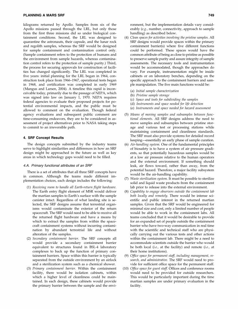
kilograms returned by Apollo. Samples from six of theApollo missions passed through the LRL, but only thosefrom the first three missions did so under biological con-tainment conditions. Second, the LRL was designed toquarantine the astronauts, their capsule, and the lunar rockand regolith samples, whereas the SRF would be designedfor sample containment and contamination control only.(Sample containment refers to the protection of humans andthe environment from sample hazards, whereas contamina-tion control refers to the protection of sample purity.) Third,the process for securing approvals for construction of facili-ties has changed significantly. The LRL was completed infive years: initial planning for the LRL began in 1964, con-struction took place from 1966–1967, operational tests beganin 1968, and certification was completed in early 1969(Mangus and Larsen, 2004). A timeline this rapid is incon-ceivable today, primarily due to the passage of NEPA, whichwas signed into law on January 1, 1970. NEPA requiresfederal agencies to evaluate their proposed projects for po-tential environmental impacts, and the public must beallowed to comment on the evaluation. Though federalagency evaluations and subsequent public comment aretime-consuming endeavors, they are to be considered in as-sessment of project alternatives prior to NASA taking stepsto commit to an irreversible path.
4. SRF Concept Results
The design concepts submitted by the industry teamsserve to highlight similarities and differences in how an SRFdesign might be approached in the future as well as keyareas in which technology gaps would need to be filled.
4.A. Primary functional attributes of an SRF
There is a set of attributes that all three SRF concepts havein common. Although the teams made different im-plementation choices, each design includes the following:
(1) Receiving room to handle all Earth-return flight hardware.The Earth entry flight element of MSR would deliverthe martian samples to Earth’s surface with the samplecanister intact. Regardless of what landing site is se-lected, the SRF designs assume that terrestrial organ-isms would contaminate the exterior of the returnspacecraft. The SRF would need to be able to receive allthe returned flight hardware and have a means bywhich to extract the samples from within the space-craft containment systems without incurring contami-nation by abundant terrestrial life and withoutalteration of the samples.
(2) Secondary containment barrier. The SRF concepts allwould provide a secondary containment barrierequivalent to structures found in BSL-4 laboratorycomplexes to back up the function of primary con-tainment barriers. Space within this barrier is typicallyseparated from the outside environment by an airlockand a sterilization system such as a chemical shower.
(3) Primary containment barrier. Within the containmentfacility, there would be isolation cabinets, withinwhich a higher level of cleanliness could be main-tained. In each design, these cabinets would providethe primary barrier between the sample and the envi-
ronment, but the implementation details vary consid-erably (e.g., number, connectivity, approach to samplehandling) as described below.
(4) Clean spaces for activities involving the pristine samples. AllSRF designs would provide spaces within the primarycontainment barrier(s) where five different functionscould be performed. These spaces would have thecommon attribute of being as close to pristine as possibleto preserve sample purity and assure integrity of sampleassessments. The necessary tools and instrumentationwould be accommodated, though the approaches dovary. For example, instrumentation might be insidecabinets or on laboratory benches, depending on thespecific approach to the containment barriers and sam-ple manipulation. The five main functions would be:
(a) Initial sample characterization(b) Pristine sample storage(c) Space and tools for subdividing the samples(d) Instruments and space needed for life detection(e) Instruments and space needed for hazard assessment
(5) Means of moving samples and subsamples between func-tional elements. All SRF designs address the need tomove samples and subsamples between pristine stor-age and various test or processing stations whilemaintaining containment and cleanliness standards.The SRF must also provide systems for detailed recordkeeping—essentially an early phase of sample curation.
(6) Air-handling system. One of the fundamental principlesof biosafety is to have a system of air pressure gradi-ents, so that potentially hazardous samples would beat a low air pressure relative to the human operatorsand the external environment. If something shouldleak, air flows toward, rather than away, from thepotential hazard. Therefore, a major facility subsystemwould be the air-handling capability.
(7) Waste sterilization system. It must be possible to sterilizesolid and liquid waste products from the containmentlab prior to release into the external environment.
(8) Capability to engage observers outside the containment labboth locally and remotely. There would be intense sci-entific and public interest in the returned martiansamples. Given that the SRF would be engineered forminimal size and cost, only a limited number of peoplewould be able to work in the containment labs. Allteams concluded that it would be desirable to providefor an expanded set of people outside the containmentbarrier who have two-way communication in real timewith the scientific and technical staff who are physi-cally carrying out the various tests and other actionswithin the containment lab. There might be a need toaccommodate scientists outside the barrier who wouldbe both local (i.e., at the facility) and remote (i.e., attheir home institutions).
(9) Office space for permanent staff, including management, re-search, and administrative. The SRF would need to pro-vide for sufficient office space for the permanent staff.
(10) Office space for guest staff. Offices and conference roomswould need to be provided for outside researchers.This would be particularly important during the timemartian samples are under primary evaluation in thefacility.
PLANNING A MARS SRF 749

(11) Laboratory and engineering support facilities. Severaltypes of facility support functions would need to beaddressed, including cleaning and sterilization ofequipment, instrumentation support and calibration,and provision of purified water and gases.
(12) Facility security system. When returned, the martiansamples would be entities of singularly high value.Physical security to protect against theft, vandalism,and terrorism would be required.
(13) Other. To ensure containment and contamination con-trol, the SRF would require operator safety systemssuch as fire protection, emergency oxygen supplies, anuninterruptable power supply, and other backup sys-tems. The SRF would need to be operated under con-trolled conditions, including humidity, temperature,and potentially inert gas. The facility would need thecapability to test and monitor all its essential safetysystems and their backups. The facility must be able tomaintain containment under a variety of off-nominalconditions, including power failure.
4.B. FLAD team concept
The FLAD team developed a preliminary concept of con-tainment and identified the aspects of the preliminary conceptthat would require additional research before the conceptcould be developed further. They proposed a design thatfeatures three types of containment laboratories, each withunique functions. These laboratories would be located aboveutility and waste-treatment spaces and below air-handlingspaces with roof exhausts. This design is similar to most BSL-4labs currently operating in the United States (Fig. 1).
Laboratory 1 would be a glovebox2 facility, designed formanual initial processing of the spacecraft and samples.
Laboratory 2 would also be a glovebox facility that woulduse robots to perform initial sampling, subdivision, andsample testing. Gloves would be used only for maintenanceand initial placement of equipment. Gloves would be sealedoff during normal operations. Laboratory 3 would be a tra-ditional BSL-4 suit facility, designed for biohazard and lifedetection, including small animal studies. All laboratorieswould be supplied with high efficiency particulate air(HEPA) filtered air, and each would have a separate com-bination of biological containment and air cleanliness ap-propriate to its operation.
The ‘‘gloveboxes’’ would be linked double-walled Class IIIBiological Safety Cabinets (BSCs), with reduced pressurebetween the walls (Fig. 2). This technology is designed tominimize contamination of both the laboratory and thesamples in the event of a leak. The double-walled version ofthese cabinets and their associated gloves are not currentlyavailable (they are concept only), and represent significantdesign and operating challenges. While the single-walledversions are an accepted alternative to suits for BSL-4 oper-ations, the double-wall technology would require detailedstudy to warrant such acceptance.
The FLAD SRF concept would include robots to performinitial sampling, subdivision, and sample testing. The currentgeneration of industrial robots, particularly those used in mi-croelectronics fabrication, has an impressive record of flexi-bility, reliability, and cleanliness. However, the capabilities ofspecific robots in the unique SRF environment must be thesubject of extensive development, testing, and verification.
4.C. LAS team concept
The LAS team concept is a fully robotic SRF, with theexception of the in vivo biohazard testing. All sample han-dling, testing, and storage would be carried out inside oneinterconnected, multi-branching train of Class III BSCs(Fig. 3). The various branches would lead to different clus-ters. In the central node of each cluster, a robotic arm wouldperform the operations on the samples with specially de-signed end effectors, tools, instruments, and equipment.These robotic arms might have 6 degrees of freedom if nee-ded for complex motions, or be a simpler type for movingsamples from one station to another.
FIG. 1. Sample Receiving Facility cross section(FLAD). Samples would be processed and tes-ted in three separate laboratories. These labo-ratories would be supported by extensive airfiltration and waste-handling equipment, lo-cated above and below the laboratories,respectively. Color images available online atwww.liebertonline.com=ast.
2Class III Biological Safety Cabinets are sometimes called ‘‘glo-veboxes.’’ In this device, the interior of the cabinet is maintainedunder negative pressure (relative to the room), with HEPA filtersattached to the supply and exhaust air systems. Class III BSCs can beconnected together so that different activities can be performed se-quentially on samples in containment. Autoclaves, incubators, dunktanks, sample-transfer ports, and animal caging may be connected tothe glovebox line.
750 BEATY ET AL.

A significant driver for the LAS team’s SRF concept is theconsideration that, based on past BSL-4 experience, mostbreaches in containment are related to human error of onetype or another and, in particular, issues associated with the
gloves. In addition to susceptibility to needle punctures andother kinds of material failure, there are risks to the samplesof imprecise manipulation of very small objects by double-gloved human hands. LAS proposed a design by which ro-botic manipulators would be employed, to the maximumextent possible, for direct contact with samples. Since mul-tiple activities would need to be performed on the samples,this would require multiple isolator boxes and multiple ro-botic manipulators. LAS made the case that this approachwould be the lowest-risk, both from the point of view ofsample contamination and containment assurance, though itwould clearly not be the lowest cost.
This concept would require a relatively small primarycontainment area that would use robotics to minimize hu-man exposure and contamination. Biohazard testing wouldbe carried out in a separate BSL-4 suit laboratory. Theselaboratories would be located above utility and waste-treatment spaces and below air-handling spaces.
The LAS team concept would use robots in most phases oflaboratory operations, including spacecraft dismantling, re-moval of samples from their containers, initial sample char-acterization and subdivision, subsample packaging andtransport, sample testing and analysis, and storage. Humanswould perform hands-on maintenance and repair via glo-veports. The capabilities of robots to perform all these tasksunder stringent cleanliness and biosafety requirementswould require extensive development, testing, and verifica-tion.
A unique feature of the LAS approach is the use of‘‘common carriers’’ to transport and contain subsamples. Theuse of such devices is standard in the electronics fabricationindustry, where conditions of extreme cleanliness are main-tained in these ‘‘mini-environments’’ without requiring suchstringent cleanliness in the entire laboratory.
The LAS team report also devotes considerable attentionto the subjects of decontamination and sterilization. The SRFmust have the capability to decontaminate and sterilize theentire laboratory, specific containment vessels, robots, andindividual components. Sterilization techniques are welldeveloped in industrial and research laboratories but would
FIG. 2. Double-walled BSC schematic (FLAD). Sampleswould be stored and tested under nitrogen gas in the innerchamber, which would be held at negative pressure withrespect to the surrounding room. Contamination from eitherthe sample or the room would be captured in the outerchamber, which would be held at even lower pressure. Colorimages available online at www.liebertonline.com=ast.
FIG. 3. Fully robotic SRF floor plan (LAS)concept. Samples would be manipulated byrobotic arms in an interconnected series ofBSCs. Individual samples would be containedand transported in extremely clean ‘‘commoncarriers.’’ Color images available online atwww.liebertonline.com=ast.
PLANNING A MARS SRF 751
need to be adapted to the unique requirements of the SRF.That is, decontamination techniques (i.e., complete removalof organic and biological materials and contaminants) are notwell developed, since, ordinarily, sterilization is deemedsufficient.
4.D. IDC team concept
The IDC team designed an SRF that would make minimaluse of robotics technology. Their design features separateclean-room laboratories for physical and chemical testing,life detection, and biohazard testing (Fig. 4). Sample han-dling, physical and chemical testing, and storage would beconducted in separate, controlled-atmosphere ‘‘isolator’’gloveboxes.3 The isolators would be maintained at negativepressure with respect to the laboratory, with HEPA filteredinteriors for a Class 10 clean environment to protect thesamples. The isolators would be located in BSL-3 level labrooms that would allow the staff to be dressed in lab gar-ments, rather than positive-pressure personnel suits.
The isolators would not be interconnected, so each cabinetmust be self-sufficient (i.e., with its own airlock, gas supplies,etc.). Samples would be moved between isolators by way of‘‘rapid transfer ports.’’ These containers would feature adouble-door transfer system that would permit docking andundocking from isolators while maintaining biocontainment.Rapid transfer ports were originally developed for the nu-clear industry but are now accepted for sample transport inhigh-level biosafety laboratories.
4.E. Comparison of sample processing approaches
In our comparison of results of the studies, we focus onthe key characteristics associated with the sample processingfunctions, with minor discussion of facility maintenance andsupport staffing costs. The sample processing functionscould be grouped into five steps, as outlined in Table 1, alongwith a summary of each team’s approach. Any credible ap-proach to each processing step must address both cleanlinessand primary containment.
Containment approach. One method of containmentcommon to the three industry studies is the use of Class IIIBSCs for primary containment in the initial sample proces-sing steps. These cabinets would provide the highest level of
FIG. 4. Minimal robotic SRF floor plan (IDC). Samples would be stored and manipulated in individual glovebox isolators.Material would be moved between isolators via rapid-transfer ports. Color images available online at www.liebertonline.com=ast.
3‘‘Isolators’’ are not necessarily ‘‘gloveboxes.’’ The term ‘‘isolator’’is generally used to describe a bacteriology incubation device thatmay have gloves attached.
752 BEATY ET AL.

protection of the external environment from the internalcontents. They are used in many industrial and biologicalresearch labs to provide the primary containment. They areof gas-tight construction but ventilated to provide criticalenvironmental control, with both incoming and outgoingHEPA filtration.
The three industry study concepts also use other criticalcontainment methods common in BSL-4 laboratories andfacilities. They include careful designs of the lab space sur-
rounding the BSCs, special waste treatment, air handling andutility systems, as well as safety and security provisions.
Cleanliness. All study concepts make use of many im-portant cleanliness methods. For example, all three conceptspropose the use of double-walled BSCs that, in addition tocontainment, would provide some protection for the sam-ples. Also, in the initial process of dismantling the Earth-return vehicle, all three concepts would clean and sterilize
Table 1. SRF Sample Processing Function and Team Approaches
Step Function FLAD approach LAS approach IDC approach
Summary approach to hardwareand sample flow
Three-lab design withmixture of roboticand operatormanipulation ofsamples
Robotic-assistedsample processingin containment vesselline plus BSL-4 in vivolab for biohazard test
Large clean lab withspecializedisolators; mainlyoperatormanipulation ofsamples
1 Receive all Earth-return flighthardware andperform initialdisassembly
Mobile containmentmodule mated to oradmitted throughairlock tocontainmentmodule (CM) in Lab1. Personnel in labgarments would useglove ports andmechanical assistsin CM.
Sealed mobilecontainment modulewould be moved intoCM using roboticmanipulation andmechanical assists.Truck dock roomprovided in design.
Upon arrival, EarthEntry Vehicleplaced underindustrial hood,cleaned bypersonnel usingglove ports andtools in BSL-3 attire,then moved intoisolator in clean lab.
2 Receive samplecanister andperform initialdisassembly andsample inspection;initiate subsamplingand physical testing
Sample canistertransitions to Lab 2with higher controlsto protect samples.Mainly roboticmanipulation inCMs. Samplestransferred incommon carriers.
Robotic manipulationin specializedcharacterizationclusters. Samplestransferred incommon carriers.
Manipulation ofsample canister andsamples bypersonnel in labgarments usingglove ports andtools in CM.Physical testing inClass 10 clean room.
3 Perform chemical andlife-detection testingon samples
Continued work inLab 2. Roboticmanipulation inCMs. Samplestransferred incommon carriers.
Robotic manipulationin specializedcharacterizationclusters. Samplestransferred incommon carriers.
Manipulation ofsamples bypersonnel in labgarments usingglove ports andtools in CM. Class10 clean room.
4 Perform biohazardtests on samples
Some continued workin Lab 2. Remaininglife-detection andbiohazard testing inLab 3 or alternatefacility. Personnel inBSL-4 class suitswork with animals,plants, cultures, etc.
Samples move throughairlock tobiocontainment area.Personnel in BSL-4class suits work withanimals, plants,cultures, etc. Usebiosafety cabinetsand gloveboxes.
Manipulation ofsamples bypersonnel in labgarments usingglove ports andtools in CM.
5 Store samples inpristineenvironments
To be worked. Tested samplesretained at eachcharacterizationcluster for interimstorage. Remainingsamples kept inpristine storage.
Repetitive storage andretrieval tasks usetelemanipulation inisolators formaximumprotection ofsamples.
CM, containment module.
PLANNING A MARS SRF 753

the outside of each spacecraft element and transfer thecleaned element(s) into the next pristine BSC.
Disparate sample sizes. All three concepts share someessential characteristics, such as their capability to deal withall forms of material likely to be contained in the returnedsample. For example, all three SRF concepts plan to use ap-propriate forms of containers and tools=end effectors for gas,fines (<1 mm), coarse material (>1 mm), and ‘‘large rocks.’’The designs presented in the three study concepts also sharethe capability to capture the martian atmospheric gases,separate dust from this sample, and package each for testingand storage. They also have in common the notional capa-bility to perform physical, chemical, life-detection, and bio-hazard testing on a portion of each solid sample.
The differences in the designs originate primarily fromdifferent ways to approach three issues:
(1) Approach to maintaining sample purity. The strategy ofMSR would include bringing samples that mightcontain little or no evidence of life into an environment(an Earth laboratory) where sources of life-relatedcontamination are essentially everywhere. Getting alaboratory ‘‘blank’’ down to as low a level as possiblewould likely take heroic efforts. Since human beingsare a major potential source of biological contamina-tion, it is important to carefully consider the proximityof humans to the martian samples.
(2) Approach to containment assurance. While the notion thatany returned martian samples must be kept isolated isnot unique, reduction of terrestrial contamination to anacceptable risk threshold could be established in anumber of different ways.
(3) The relationship of instrumentation to the containmentsystem. Would all the instruments required to carry outthe purpose of the SRF need to be placed inside theisolator cabinets (the primary containment system), orcould some of them be operated in an open laboratory?Some of the instruments that would be required by thetest protocol might include relatively sophisticateddevices, such as scanning electron microscopes or massspectrometers.
4.F. Building size, cost, and schedule
At the heart of the motivation to conduct the SRF conceptstudies was the need to gain a better understanding of pa-rameters relevant to program planning—facility scope orsize, cost, and timing. The reports that were delivered,combined with some interpretation to enable direct com-parison, provided insights in each key area.
(1) Building size. A key objective of this study was to es-timate the minimum building size that would be suf-ficient to carry out the SRF function. The overall facilitysize estimated by three independent groups rangedfrom about 35,000 to 60,000 square feet. This floorspace could be broken down as follows:
(a) 25,000–40,000 square feet of space related to thecontainment labs that constitute the facility core.This would include not just the contained labora-tory rooms (which are estimated to be about 5,000–
10,000 square feet, depending on the implementa-tion concept) but also the gowning area(s), decon-tamination showers, waste storage and treatment,interstitial space, clean sample storage, airshafts,and the perimeter corridor. The sample receivingrequirements imply a receiving dock connected toa decontamination laboratory, which would needto be part of the containment core of the laboratory(one of its functions would be to test the spacecraftseals)—its space needs are estimated to be about1,000 square feet for the decontamination lab andan additional 1–2 times that for the uncontainedreceiving dock and an associated support lab.
(b) 10,000–15,000 square feet of office, administrative,and logistical support space (including storage,security).
(c) *5,000 square feet of high-containment lab-support space (including testing shops).
(2) Cost. Each of the three design teams estimated the costand cost profile based on the SRF scenario that waspresented to them and their interpretation of how tobest implement it. At the end of the industry studies,the Mars Program study lead normalized the threedifferent team estimates to place them on as compa-rable a footing as possible, and a composite budgetprofile was prepared (Table 2). The annual budgets inthe composite are expressed in units of dollars for eachrespective fiscal year (so-called ‘‘real year’’ dollars),with an overall total of $121 million. The permanentstaff necessary to operate the SRF is estimated to beabout 20–30 persons, for an annual operational cost of$7 million. This estimate includes single-shift admin-istrative, facility support and maintenance, and core
Table 2. Estimated Cost to Design, Build,
and Operate an SRF
Assume MSR launches in 2013, samples arrive on Earth in 2016
Annual budget(millions,
real-year dollars) Life-cycle phase
FY05 0.2 Oversight of advancedtechnology development,site selection
FY06 0.6FY07 1 DesignFY08 2FY09 3FY10 10FY11 26 ConstructionFY12 23FY13 22 CommissioningFY14 7 Training, operational
readiness testingFY15 7FY16 7 Samples arrive, are active
within facilityFY17 7FY18 5Total 121
FY, fiscal year.
754 BEATY ET AL.

building operations staff. These figures do not includethe large number of personnel that would be requiredto carry out the work of the Test Protocol, such asguest scientists, planetary protection officials, andplanetary program managers during the years of ac-tive sample handling and study within the SRF. Ad-ditionally, we caution that this cost estimate also doesnot include the research and technology developmentefforts necessary to provide key functionality in theSRF. Although this cost profile and total cost is specificto the study scenario, it might be adjusted to alternatefuture scenarios by applying the appropriate inflationfactors. To make such a cost adjustment to alternativeor future scenarios, it is crucial to refer to the key un-derlying assumptions concerning schedule and costbasis that were presented earlier in Section 3E.
(3) Schedule. The three teams each analyzed the schedulethat would be needed to acquire permits, conductdesign, construct the facility, and commission the SRFthey envisioned. The estimated total schedule durationfrom the start of concept design and site selection ac-tivities to readiness to receive samples is approxima-tely 7 years. Note that this estimate does not includethe significant research and development effort re-quired to reach the ready-to-build stage. Additionally,this schedule is estimated to vary by 1 to 2 years,primarily depending on whether NASA used an in-ternal or external site selection process (an internal siteselection process would mean that only propertiesunder the jurisdiction of the Federal Government areconsidered, whereas external site selection wouldmean that private landowners, state governments, andinstitutions could also propose facility locations). Theschedule would have to be lengthened by approxi-mately 2 years should an external property purchasebe required. For comparison, Rummel et al. (2002) andAtlas (2008) estimated that this amount of work wouldtake 9 years and 10 years, respectively. An obviousdifference is that these industry study teams were ac-customed to designing and constructing buildings inan environment where things move more quickly thanmight be true of this unique SRF project.
4.G. Areas for further analysisand technology development
Analysis of the SRF design trade space has identifiedseveral major recognizable technology gaps [see also theplanning reported by Mattingly et al. (2005), which wasbased on the same SRF studies reported in this paper] andsome areas requiring further analysis.
Decontamination techniques. Methods for removing organic,inorganic, and particulate contamination from containers,BSCs, robotic manipulators, and hand tools coming intocontact with the samples or their environment.
Double-walled glovebox containment. Design, fabrication,testing, and certification of a biosafety cabinet with a doublewall enclosing a low-pressure space, designed to trap leak-age from the samples as well as contaminants from theoutside laboratory.
Robotics. Demonstrate operations of dexterous ultra-cleanrobots capable of sample transport and sample manipulation
(see also Mani et al., 2008). As pointed out by Bell and Allen(2005), a key issue is whether the robotics can be madecompatible with the cleanliness requirements.
Pristine sample preservation. Methods of preserving martianrock, soil, and atmosphere samples for long-term storage anddistribution to researchers in a wide variety of disciplines.
Scientific equipment required for proper sample analysis. Spe-cific instruments to conduct the testing required for assess-ment of possible life and biohazards in martian rock, soil,and atmosphere samples.
5. Discussion and Future Planning
Three independent industry studies produced comple-mentary high-level concepts for an SRF dedicated to an MSRmission. These industry study concepts represent a ‘‘snap-shot in time’’ relative to our understanding of the charac-teristics of martian samples, the nature of a sample returnmission, the requirements of planetary protection, and therole of international collaboration and regulations in themission. These detailed studies will need to be redone atsome point in the future in light of our updated knowledgeof Mars, an updated Test Protocol (note the emphasis on thisin Atlas, 2008), the possible internationalization of MSR (e.g.,iMARS, 2008; Mani et al., 2008), and our evolving budgetaryand political realities.
5.A. Some considerations affecting SRF size and cost
The cost presented above is based on a specific scenario,with a circumscribed set of assumptions and requirements.However, the size and cost of the SRF is sensitive to theseveral possible changes in the assumptions and require-ments, some of which might have significant effect on itscost.
Partnering options. The SRF scenario evaluated in thisstudy was assumed to be a single, new, stand-alone building.Locating this building as part of a campus of other buildingscould enable the sharing or avoidance of certain costs, suchas perimeter security, access to transportation and utilities,access to a trained technician pool, avoidance of legallyprotected areas, and so forth. Although the general potentialfor cost saving is obvious, this cannot be evaluated in detailwithout specific designs.
Making use of existing construction. A single, new,stand-alone building is the simplest (and perhaps the only)way to meet the expected cleanliness requirements. How-ever, it may be possible to configure the SRF as a newlyconstructed wing of an existing building, or perhaps even asa retrofit of an existing building.
Live animal testing. Because the present Draft Test Pro-tocol (Rummel et al 2002) calls for conventional whole-organism animal and plant in vivo testing, a significant partof the floor space of the containment laboratory core in thethree scenarios relates to animal holding and evaluationareas. Since the Draft Test Protocol was published in 2002and used as a key element of the baseline requirementsfor the 2004 industry study concepts, the fields of microbi-ology and biohazard detection have advanced markedly.The limits of detection and classification of microbial life in
PLANNING A MARS SRF 755

environmental samples have improved significantly, and theuse of animals in biohazard testing has been increasinglyreplaced by cellular and molecular analyses. If a future ver-sion of the test protocol eliminates this requirement in ac-cordance with state-of-the-art practices and refinements atthe time the final protocol is implemented, the SRF designwould potentially be simpler.
More than one SRF. The study teams each analyzed thedesign, construction, and operation of a single SRF. How-ever, in the future it might be possible or required that thereare two or more SRFs in different locations, possibly in dif-ferent countries. If there are multiple SRFs, they could con-ceivably either be designed with identical capabilities or,alternatively, with the capability to perform different, com-plementary tests. The possibility of a two-SRF scenario hasbeen discussed both within the 2003–2005 MSR Project andby iMARS (2008) as a potentially desirable, or perhaps evenpolitically necessary, attribute of an international MSR mis-sion. A specific variation on the single-SRF approach (al-luded to by Rummel et al 2002 in the Draft Test Protocol) isthe possibility that live animal testing could be done in asecondary facility that meets the biocontainment require-ments of the SRF, which would thus simplify the design andcost of the primary facility. A prerequisite for any two-SRFscenario would be a means by which to move unsterilizedsamples between facilities and the approval to do so.
SRF expandability. This study evaluated the minimumpossible SRF that would be required to execute the testprotocol. If the samples are determined to be non-hazardous(or are rendered non-hazardous by sterilization), they wouldbe made available for allocation to the world’s researchcommunity. However, if signs of life are detected in one ormore samples, it might become necessary for future study ofthe returned samples to take place in ongoing containment.The samples would then need to be evaluated with addi-tional methods beyond those used in the Draft Test Protocol.The SRF may need to be designed so that it could be ex-panded to accommodate additional laboratories; if thisfunctional requirement were accepted, it could have signifi-cant cost implications.
6. Conclusions
Based on the analysis and interpretation of the 2004 in-dustry study concepts, we suggest the following consider-ations for planning an SRF to meet the needs of a future MSRmission.
(1) Design. There is more than one possible design for astand-alone SRF that would meet the requirements ofMSR. Because the full set of requirements is not de-fined at this time, it is not possible to optimize thedesign. However, it is possible to understand the likelypossibilities enough to generate first-order budgeting=planning parameters.
(2) Size. A minimal stand-alone SRF is estimated to havean overall size of about 35,000–60,000 square feet, in-cluding 25,000–40,000 square feet of containment-related space that makes up the facility core (of which5,000–10,000 square feet are the high-containmentlaboratory rooms; the remainder would consist of
facility support systems including air handling, che-mical showers, waste cookers, etc.), up to 5,000 squarefeet of high-containment lab support space (test andrepair shops), and 10,000–15,000 square feet of office,administrative, and logistical support space (includingstorage and security).
(3) Schedule. The schedule needed to construct and com-mission an SRF is estimated to be 7–9 years. Most ofthis variance relates to whether NASA uses an internalor an external site selection process. Because of theschedule-constrained nature of an MSR (i.e., once thesamples have left Mars, spacecraft trajectories have adefined schedule that cannot be easily slipped), it isprudent to add additional schedule reserves, and agood planning number is 10 years.
(4) Capital cost. The cost of an SRF would depend upon thespecific design approach, as well as on the final testprotocol executed in the facility. However, for futureplanning a reasonable budget estimate is the escalatedequivalent of $120 million real-year dollars, using the2013 MSR scenario described in Table 2.
(5) Operating cost. During the years the martian sampleswould be evaluated in the facility, the annual buildingoperating budget would be estimated at $7 million,which includes a building operations staff of 20–30persons. This estimate does not include the largenumber of personnel that would be required to carryout the work of the Test Protocol.
(6) Advance technology development. Most of the technologyneeded to design and construct an SRF already existsin the biosafety, pharmaceutical, and sample curationcommunities. However, along with decontaminationtechniques, double-walled glovebox containment,dexterous ultra-clean robotics, pristine sample preser-vation, and scientific equipment required for propersample analysis, some aspects of the project will needto be planned at two specific points in the building lifecycle: (a) those that affect the facility design and willneed to be known before facility construction, (b) thosethat affect the instrumentation, the experiments, orboth, that will need to be known before the facility isequipped.
(7) Partnering opportunities. Although not fully analyzed inthe industry study concepts, it is likely that partneringopportunities might result in cost savings, operationalefficiency, or other benefits. Such opportunities couldbe evaluated against the reference planning parame-ters described above to determine whether this wouldbe a better way to meet the needs of an MSR than witha stand-alone SRF.
7. Acknowledgments
The authors wish to recognize the teams and dedicatedindividuals at Industrial Design and Construction (IDC) ofPortland, Oregon; Lord, Aeck, Sargent (LAS) of Atlanta,Georgia; and Flad & Associates (FLAD) of Madison, Wis-consin, for their diligence, interest, and hard work thatcomprises the core of this paper. We also want to acknowl-edge study participant and reviewer Jonathan Richmond,and members of the 1999–2002 Mars Returned SampleHandling team Lisa Fletcher, Mary Sue Bell, Judy Allton,
756 BEATY ET AL.
Stan Farkas, Geoff Briggs, Laurie Carrillo, Kimberly Cyr,Sandy Dawson, Janis Graham, Ragnhold Landheim, RoccoMancinelli, Ed Mickelson, and Nancy Robertson, whosework led up to the SRF design studies. Thanks also toMargaret Race, John Rummel, and Joe Parrish who all con-tributed to our understanding during the planning andperformance of the SRF design study effort; Jeff Schanz, whoprovided continued technical assistance after the delivery ofthe studies; and reviewer Richard Mattingly. The researchdescribed in this paper carried out at the Jet Propulsion La-boratory, California Institute of Technology, was done sounder a contract with the National Aeronautics and SpaceAdministration.
8. Author Disclosure Statement
No competing financial interests exist. The cost informa-tion contained in this document is of a budgetary andplanning nature and is intended for informational purposesonly. It does not constitute a commitment on the part of JPLand=or Caltech.
9. Abbreviations
BSC, Biosafety Cabinet or Biological Safety Cabinet; BSL,Biosafety Level; CAPTEM, Curation and Analysis PlanningTeam for Extraterrestrial Materials; FLAD, Flad & Associ-ates; HEPA, high efficiency particulate air; IDC, IndustrialDesign and Construction; LAS, Lord, Aeck, Sargent; LRL,Lunar Receiving Laboratory; MSHARP, Mars SampleHanding and Requirements Panel; MSR, Mars Sample Re-turn; NEPA, the National Environmental Policy Act; NRC,National Research Council; SRF, Sample Receiving Facility.
10. References
Allton, J.H., Bagby, J.R., and Stabekis, P.D. (1998) Lessonslearned during Apollo lunar sample quarantine and samplecuration. Adv. Space Res. 22:373–382.
Atlas, R. (2008) Mars Sample Return Receiving Facility.Presentation to the Planetary Science Subcommittee. Avail-able online at http:==www.lpi.usra.edu=pss=presentations=200803=04-Atlas-PPSonMSR.pdf.
Backes, P., Onstott, T., Bar-Cohen, Y., Badescu, M., Pratt, L.,Helmick, D., Sherrit, S., Johnson, A., and Bao, X. (2009) Pla-netary sample sealing for caching. In Proceedings of the 2009IEEE Aerospace Conference, Institute of Electrical and Electro-nics Engineers, Piscataway, NJ.
Bar-Cohen, Y., Wu, J., Bley, S., Olorunsola, A.K., Rivellini, T.P.,Wincentsen, J., and Gershman, R. (2005) Simultaneous sepa-ration, seaming and sealing using brazing (S3B) for samplecontainerization and planetary protection [Paper ##5762-43].In Proceeding of the Industrial and Commercial Applications of SmartStructures Technologies, SPIE Smart Structures and MaterialsSymposium, The International Society for Optical Engineer-ing, Bellingham, WA.
Bell, M.S. and Allen, C. (2005) Cleanroom robotics—appropriatetechnology for a sample receiving facility [abstract 1395].In 36th Lunar and Planetary Science Conference, Lunar and Plan-etary Institute, Houston. Available online at http:==www.lpi.usra.edu=meetings=lpsc2005=pdf=1395.pdf.
Carr, M.H., editor. (1999) Mars Sample Handling and RequirementsPanel (MSHARP) Final Report [NASA TM-1999-209145],NASA Jet Propulsion Lab, Pasadena, California.
CDC=NIH. (2007) Biosafety in Microbiological and BiomedicalLaboratories (BMBL), 5th ed., U.S. Department of Health andHuman Services Centers for Disease Control and Preventionand National Institutes of Health, Washington, DC. Availableonline at http:==www.cdc.gov=od=ohs=biosfty=bmbl5=bmbl5toc.htm.
COSPAR (2008) COSPAR Planetary Protection Policy, Committeeon Space Research of the International Council for Science,Paris. Available online at: http:==cosparhq.cnes.fr=Scistr=PPPolicy(20-July-08).pdf.
DeVincenzi, D.L., Bagby, J., Race, M., and Rummel, J.D., editors.(1999) Mars Sample Quarantine Protocol Workshop [NASA CP-1999-208772], NASA Ames Research Center, Moffett Field,California.
Gershman, R., Adams, M., Dillman, R., and Fragola, J. (2005)Planetary protection technology for Mars Sample Return [Paper#2.1607]. In Proceedings of the 2005 IEEE Aerospace Conference,Institute of Electrical and Electronics Engineers, Piscataway, NJ.
iMARS. (2008) Preliminary Planning for an International MarsSample Return Mission: Report of the International Mars Archi-tecture for the Return of Samples (iMARS) Working Group, In-ternational Mars Architecture for the Return of SamplesWorking Group. Available online at http:==mepag.jpl.nasa.gov=reports=iMARS_FinalReport.pdf.
Mangus, S. and Larsen, W. (2004) Lunar Receiving LaboratoryProject History [NASA=CR-2004-208-938], NASA, WashingtonDC. Available online at http:==ston.jsc.nasa.gov=collections=TRS=_techrep=CR-2004-208938.pdf.
Mani, P., Nelson, B., Pauli, U., Kray, R., Huntley, P., Ross, F.,Heuer, M., and Hofmann, B.A. (2008) Preliminary conceptfor a Mars Sample Receiving Facility [abstract # PPP2-0006-08]. In COSPAR 2008, Committee on Space Research of theInternational Council for Science, Paris. Available onlineat http:==www.cospar-assembly.org=abstractcd=COSPAR-08=abstracts=data=pdf=abstracts=PPP2-0006-08.pdf.
Mattingly, R., Hayati, S., and Udomkesmalee, G. (2005) Tech-nology development plans for the Mars Sample Return mis-sion [Paper #151]. In Proceedings of the 2005 IEEE AerospaceConference, Institute of Electrical and Electronics Engineers,Piscataway, NJ.
Moura, D., Jordan, F., Pradier, A., May, L., Santovincenzo, A.,Mattingly, R., Kerridge, S., Khan, M., Gardini, B., andMcCuistion, D. (2008) The road to an international architec-ture for Mars Sample Return: The iMARS Team view [IAC-08-A3.1.3]. In The 59th International Astronautical Congress,International Astronautical Federation, Paris.
MEPAG ND-SAG. (2008) Science priorities for Mars SampleReturn. Astrobiology 8:489–535. Available online at http:==mepag.jpl.nasa.gov=reports=index.html.
NRC. (1978) Strategy for the Exploration of the Inner Planets: 1977–1987, National Academy Press, Washington DC.
NRC. (1990a) Update to Strategy for Exploration of the Inner Planets,National Academy Press, Washington DC.
NRC. (1990b) International Cooperation for Mars Exploration andSample Return, National Academy Press, Washington DC.
NRC. (1994) An Integrated Strategy for the Planetary Sciences:1995–2010, National Academy Press, Washington DC.
NRC. (1996) Review of NASA’s Planned Mars Program, NationalAcademy Press, Washington DC.
NRC. (1997) Mars Sample Return Issues and Recommendations, TaskGroup on Issues in Sample Return, Space Studies Board, Com-mission on Physical Sciences, Mathematics, and Applications,National Research Council, National Academy Press,Washington DC.
PLANNING A MARS SRF 757

NRC. (2002) The Quarantine and Certification of Martian Samples,National Academy Press, Washington DC.
NRC. (2007) An Astrobiology Strategy for the Exploration of Mars,The National Academies Press, Washington DC.
Neal, C.R. (2000) Issues involved in a martian sample return:integrity preservation and the Curation and Analysis PlanningTeam for Extraterrestrial Materials (CAPTEM) position. J.Geophys. Res. 105:22487–22506.
O’Neil, W.J. and Cazaux, C. (2000) The Mars Sample Returnproject. Acta Astronaut. 47:453–465.
Race, M.S. and Hammond, E. (2008) An evaluation of the roleand effectiveness of institutional biosafety committees inproviding oversight and security at biocontainment labora-tories. Biosecurity and Bioterrorism: Biodefense Strategy, Practiceand Science 6:19–35.
Race, M.S. and Rummel, J.D., editors. (2000) Mars SampleHandling Protocol Workshop Series. Interim Report of the Work-shop Series: Workshop 1 Proceedings and Final Report [NASA=CP-2000-209624], NASA, Washington DC.
Race, M.S., Kovacs, G.T.A., Rummel, J.D., and Acevedo, S.E.,editors. (2001a) Mars Sample Handling Protocol Workshop Series.Interim Report of the Workshop Series: Workshop 2 Proceedings andFinal Report [NASA=CP 2001-210923], NASA, Washington DC.
Race, M.S., Nealson, K., Rummel, J.D., and Acevedo, S.E., edi-tors. (2001b) Mars Sample Handling Protocol Workshop Series.Interim Report of the Workshop Series: Workshop 3 Proceedings and
Final Report [NASA=CP-2001-211388], NASA, WashingtonDC.
Rummel, J.D., Race, M.S., DeVincenzi, D.L., Schad, P.J., Stabekis,P.D., Viso, M., and Acevedo, S.E., editors. (2002) A Draft TestProtocol for Detecting Possible Biohazards in Martian SamplesReturned to Earth [NASA=CP-20-02-211842], NASA Ames Re-search Center, Moffett Field, CA.
Stephenson, D.D. and Willenberg, H.J. (2006) Mars ascent ve-hicle key elements of a Mars Sample Return mission. In 2006IEEE Aerospace Conference, Institute of Electrical and Electro-nics Engineers, Piscataway, NJ.
U.S. Department of Health and Human Services (2007) Biosafetyin Microbiological and Biomedical Laboratories, 5th ed., US Gov-ernment Printing Office, Washington DC. Available onlie athttp:==www.cdc.gov=od=ohs=biosfty=bmbl5=bmbl5toc.htm.
Address correspondence to:Deborah S. Bass
Mars Program OfficeJet Propulsion Laboratory
California Institute of Technology4800 Oak Grove Drive
Pasadena, CA 91109-8099
E-mail: [email protected]
758 BEATY ET AL.