20100201218 - defense technical information center · frequency for adding water may be determined...
TRANSCRIPT

NEWPORT
DEPARTMENT OF THE NAVY NAVAL UNDERSEA WARFARE CENTER
DIVISION NEWPORT OFFICE OF COUNSEL
PHONE: 401 832-3653 FAX: 401 832-4432
DSN: 432-3653
Attorney Docket No. 99667 Date: 27 January 2010
The below identified patent application is available for licensing. Requests for information should be addressed to:
TECHNOLOGY PARTNERSHIP ENTERPRISE OFFICE NAVAL UNDERSEA WARFARE CENTER 117 6 HOWELL ST. CODE 07TP, BLDG. 990 NEWPORT, RI 02841
Serial Number 12/693,708
Filing Date 26 January 2010
Inventor Nathan Johnnie
Address any questions concerning this matter to the Office of Technology Transfer at (401) 832-1511.
DISTRIBUTION STATEMENT Approved for Public Release Distribution is unlimited
20100201218
Attorney Docket No. 99667
BATTERY ELECTROLYTE LEVEL DETECTOR APPARATUS
STATEMENT OF GOVERNMENT INTEREST
[0001] The invention described herein may be manufactured and
used by or for the Government of the United States of America for
governmental purposes without the payment of any royalties
thereon or therefore.
CROSS REFERENCE TO OTHER PATENT APPLICATIONS
[0002] None.
BACKGROUND OF THE INVENTION
Field of the Invention
[0003] The present invention relates generally to battery
electrolyte level testing and, more particularly, to an external
apparatus and methods to check battery electrolyte levels.
Description of the Prior Art
[0004] It is well known that a wide variety of machines,
vehicles, and the like, utilize batteries with electrolyte levels
that need to be periodically checked. In lead-acid batteries,
during normal operation, sulfuric acid is not lost from the
electrolyte of the battery. However, water is lost from the
electrolyte due to evaporation and electrolysis during
ventilation and charge operations.

[0005] The water needs to be replaced regularly to ensure that
the electrolyte remains at a proper level. The required
frequency for adding water may be determined by maintaining a
close watch of electrolyte levels. If the battery electrolyte
level is too low, the battery may be permanently damaged. When
necessary, and if practical, water should be added before a
charge operation, preferably before an equalizer. This procedure
allows the water to mix with the electrolyte during the charge.
[0006] Checking the water level on batteries is time-consuming
and potentially dangerous due to the need to open the battery
caps, and look into the cells to see the level. Sulfuric acid
fumes inhalation, spillage, explosions due to hydrogen
production, and skin contact with acid are real dangers faced by
sailors testing the water level on batteries.
[0007] The following United States patents describe various
prior art systems that may be related to the above and/or other
problems.
[0008] United States Patent No. 4,280,126, issued July 21,
1981, to White discloses an apparatus for locating the level of a
liquid in a closed metallic container having curvilinear walls
with a thickness of from 1/8 to 3/8 inch comprising a manually
portable transducer having a piezoelectric material for
transmitting and receiving sonic waves, and a sonic pulse
generator capable of exciting the piezoelectric material to emit
sonic signals into the container from a location adjacent the

outside wall of such container at a frequency within about 20% of
the natural resonate frequency of the container. The apparatus
further includes the electronic circuitry necessary for
determining that the reception of the sonic signals transmitted
into the container is in balance when the transducer is at a
location away from the interface of the fluids within the
container, and the electronic circuitry necessary for determining
the vertical location at which the reception of sonic signals
transmitted into the container is no longer balanced as the
transducer is manually moved toward the interface of the fluids.
[0009] United States Patent No. 5,017,909, issued to May 21,
1991, to Goekler discloses a non-intrusive fluid level detector
including a single point capacitive sensor mounted on the outside
surface of a receptacle such that capacitive principles can be
utilized to sense the level of a liquid contained within the
receptacle. The sensor assembly is disposed in a substantially
fixed position on the exterior wall of the receptacle wherein the
dielectric effect of the liquid changes the effective capacitance
of the sensing capacitor as the liquid rises and falls within the
receptacle. This change in effective capacitance is detected by
electronic circuitry included in the detector device. In one
embodiment, the fluid level detector is directly mounted to a
completely non-conductive receptacle. In another embodiment, the
fluid level detector is mounted to a non-conductive window which
is an integral part of a receptacle fabricated out of a
conductive material.
[0010] United States Patent No. 5,132,626, issued July 21,
1992, to Limuti et al, discloses nonintrusive sensors capable of
measuring various storage cell parameters such as voltage, state-
of-charge, electrolyte level, internal resistance, and
temperature are attached to a monitoring module which gathers and
processes signals representative of information concerning the
condition of electrolytic storage cells and transmits the
information to a central computer for further processing. In
response to commands issued by the central computer, appropriate
maintenance and/or repair operations can be initiated.
Alternatively, the system described can be used to automatically
perform such maintenance tasks as checking and adding electrolyte
levels, reducing the voltage in cells whose output voltage is too
high, and leveling the state-of-charge of each cell in an array
of electrolytic storage cells. The system can monitor other
functions of the electrolytic storage cells, including the
evolution of hydrogen gas and the accumulation of sediments in
individual electrolytic storage cells.
[0011] United States Patent No. 5,438,868, issued August 8,
1995, to Holden et al, discloses a noninvasive ultrasonic liquid
level indicator for indicating the level of a liquid in a
reservoir which comprises an ultrasonic transducer assembly,
structures for holding the transducer assembly in a dry coupled

attachment with the reservoir at selectable locations against an
exterior surface of the reservoir, and a monitor for revealing a
change in liquid height. The transducer assembly conveys signals
regarding changes in liquid height to a monitor which warns the
user in time to add more liquid or replace the reservoir before
the liquid supply "runs dry." The manners for holding the
assembly in place include, but are not limited to, a strap, a
clamp, or adhesive material, such as tape. These manners allow
the user to selectively place the transducer assembly along the
reservoir at the desired triggering point.
[0012] United States Patent No. 5,880,364, issued March 9,
1999, to Dam discloses a non-contact ultrasonic system for
measuring the volume of liquid in a container in which an
ultrasonic sensor is disposed opposite the top of the container.
A circuit provides pulses of ultrasonic energy for transmission
through the air to the air-liquid interface of liquid in the
container and for measuring the round trip transit time from the
sensor to the interface and back to the sensor. A computer is
programmed with dimensional data of the container internal volume
and computes the volume of liquid in the container based on the
dimensional data and the round trip transit time. The computed
volume data is stored. The system can measure the volume of a
plurality of containers using a plurality of sensors that are
operated in sequence or at the same time or single sensor in
which the plurality of sensors are moved relative to the single

sensor for the volume of each of the sensors to be sequentially
measured.
[0013] United States Patent No. 6,227,053, issued May 8, 2001,
to Purpura et al, discloses a sensor that emits a plurality of
ultrasonic bursts. A rack of containers is transported under the
sensor at a slew speed that allows the sensor to detect at least
first and second echoes from each of the bursts. Data points,
corresponding to each of the first and second echoes, are
generated and the data points are captured in a memory device.
The data points, generally reflecting the levels of the rack and
any containers, are processed to dynamically and non-invasively
(i.e., without physically contacting the liquid with a probe)
determine information about the container types, whether any
container is capped, and, if one or more containers are uncapped,
the liquid level in the uncapped containers. This profiling may
be used in a variety of devices and is particularly useful in a
sample handler in an automated analytical instrument, where the
ultrasonic sensor may be positioned above a rack transport
mechanism.
[0014] United States Patent No. 6,943,566, issued September
13, 2005, to Florin et al, discloses a sensor which is applied to
the wall of a container or is integrated into the wall. An
alternating voltage is applied to the sensor in order to measure
the level of the contents of the container, the capacitance or
the electrical field produced being a measure for the fill level.

[0015] United States Patent Publication No. 2002/0083766,
published July 4, 2002, for Hongerholt et al, discloses a built-
in test system for an ultrasonic liquid level sensor that
includes a transducer assembly having an ultrasonic transducer,
and a switch that will be actuated when the ultrasonic transducer
is in intimate contact with a surface of a tank in which level is
to be determined. Once the switch is actuated to indicate that
the ultrasonic transducer is properly coupled to the surface, a
test sequence is initiated to determine that the level of
ultrasonic transmissions are above a certain desired threshold
for a selected period of time, and after which the circuit looks
for echoes to determine the depth of the liquid in the tank.
Thereafter, the test sequence is repeated for each cycle of level
sensing.
[0016] United States Patent Publication No. 2001/0015099,
published August 23, 2001, for Blaine, discloses a disposable
sensor for non-invasively detecting and characterizing a
container's contents. By generating microwave frequency signals,
electromagnetic fields are produced by a sensor and penetrate a
container. The EM fields are analyzed in regards to how they are
perturbed by the container contents. Analysis of the perturbed
EM fields enables determination of content level, content purity,
content density, content temperature, container pressure, content
conductivity, and the like.

[0017] U.S. Patent Publication No. 2007/0261487, published
November 15, 2007, for Sintes et al, discloses a level sensor for
providing an indication of liquid level in a container
comprising: an ultrasonic transducer for emitting an ultrasonic
signal to the surface of the liquid and for detecting a return
signal, reflected from the surface, a controller that instructs
the transducer to emit ultrasonic signals and receives an
indication that a return signal has been detected, the controller
comprising a timer for measuring the time period between emission
of the ultrasonic signal and receipt of a return signal, the
determined time period providing an indication of the liquid
level, and a radio transmitter that receives an indication of the
liquid level and transmits a radio liquid level signal comprising
the level indication to a remote output unit.
[0018] Extract from Japanese Patent No. 2000-5636041,
discloses a supersonic sensor that is made to contact the outer
surface of battery case. An ultrasonic wave is transmitted
towards a battery case from an ultrasonic element of sensor. The
magnitude of ultrasonic wave reflected from an inner surface of
battery case is detected to judge liquid level inside battery
case.
[0019] Extract from Japanese Patent No. 2000-205931, discloses
a method to inspect the liquid level of a battery liquid by
setting the size of an inside surface reflected wave generated in

the first place on a boundary surface existing on an inside
surface of a battery case as an evaluation index.
[0020] The above cited prior art does not disclose a suitable
and transportable means to acoustically check battery electrolyte
levels with micrometer accuracy without opening the cell caps.
Consequently, those skilled in the art will appreciate the
present invention that addresses the above and other problems.
SUMMARY OF THE INVENTION
[0021] It is a general purpose and primary object of the
present invention to provide an improved apparatus and method for
checking the electrolyte level in a battery.
[0022] It is a further object of the present invention to
provide a safer and more efficient means for checking the
electrolyte level in a battery.
[0023] It is a still further object of the present invention
to provide a non-intrusive apparatus and method of checking the
electrolyte level to reduce the need to open the caps on the
battery.
[0024] Accordingly, the present invention provides an
apparatus for externally checking a level of electrolyte within a
battery. The apparatus may comprise elements such as a frame
which is engageable with the battery, and a first and second
micrometer carried by the frame. The first micrometer and second

micrometers may slide along the frame with respect to each other
to adjust to a size of the battery.
[0025] Other elements of the detector may comprise an acoustic
transmitter supported on a transmitter rod. The transmitter rod
may be slidably mounted with respect to the first micrometer so
that the first micrometer is operable to measure a position of
the slidable transmitter rod for placement of the acoustic
transmitter adjacent to a desired level of electrolyte within the
battery.
[0026] Similarly, an acoustic receiver is supported on a
receiver rod. The receiver rod is slidably mounted with respect
to the second micrometer so that the second micrometer is
operable to measure a position of the slidable receiver rod for
placement of the acoustic receiver adjacent the desired level of
an electrolyte within the battery.
[0027] Electronic receiver circuitry is operable to
distinguish between an acoustic signal that passes through air
indicating a low level of electrolyte within the battery and an
acoustic signal that passes through fluid indicating a
satisfactory level of electrolyte within the battery.
[0028] In one embodiment, the electronic receiver circuitry
may comprise a first band pass filter and a second band pass
filter operably connected to the acoustic receiver. The first
band pass filter is operable for passing an electrical signal
indicative of a satisfactory level of the electrolyte within the
10

battery. The second band pass filter is be operable for passing
an electrical signal indicative of a low level of electrolyte
within the battery.
[0029] The apparatus may further comprise an acoustic
transmitter director for directing acoustic transmitter energy.
The transmitter director may comprise a first transmitter socket
cup positioned adjacent to a second transmitter socket cup. The
apparatus may further comprise an acoustic receiver director for
the acoustic receiver. The acoustic receiver director may
comprise a first receiver socket cup positioned adjacent to a
second receiver socket cup.
[0030] The first transmitter socket cup may be larger in size
than the second transmitter socket cup and the first receiver
socket cup may be larger in size than the second receiver cup.
The second transmitter socket cup and the second receiver socket
cup may be positioned for contacting the battery.
[0031] The first micrometer and the second micrometer may be
pivotally mounted to the frame for stowage of the electrolyte
level detector in a compact position. The apparatus may further
comprise a handle connectable to the transmitter rod and the
receiver rod operable for simultaneous movement of the
transmitter rod and the receiver rod.
[0032] The invention also provides a method for making an
electrolyte level detector for externally checking a level of
electrolyte within a battery. The method may comprise steps such
11

as mounting a first micrometer on a frame, mounting a second
micrometer to the frame, and providing that at least one of the
first micrometer or the second micrometer is slidable along the
frame for adjusting to a size of the battery.
[0033] Other steps may comprise supporting an acoustic
transmitter on a transmitter rod, slidably mounting the
transmitter rod with respect to the first micrometer, and
providing that the first micrometer is operable to measure a
position of the slidable transmitter rod for placement of the
acoustic transmitter adjacent a desired level of electrolyte
within the battery.
[0034] The method may further comprise supporting an acoustic
receiver on a receiver rod, slidably mounting the receiver rod
with respect to the second micrometer, and providing that the
second micrometer is operable to measure a position of the
slidable receiver rod for placement of the acoustic receiver
adjacent the desired level of electrolyte within the battery.
[0035] Other steps may comprise providing an acoustic
transmitter director for the acoustic transmitter, which may
comprise a first transmitter socket cup positioned adjacent to a
second transmitter socket cup. The method may further comprise
providing an acoustic receiver director for the acoustic
receiver, which may comprise a first receiver socket cup
positioned adjacent to a second receiver socket cup.
12

[0036] The method may further comprise providing a first band-
pass filter and a second band-pass filter operably-connected to
the acoustic receiver wherein the first band-pass filter is
operable for passing an electrical signal indicative of a
satisfactory level of the electrolyte within the battery and the
second band pass filter is operable for passing an electrical
signal indicative of a low level of the electrolyte within the
battery.
[0037] The method may further comprise providing that the
acoustic transmitter director and the acoustic receiver director
are comprised of soft plastic material. Also, the method may
further comprise filling the first transmitter socket cup and the
first receiver socket cup with acoustic couplant.
[0038] The method may further comprise providing that the
first transmitter socket cup is larger in size than the second
transmitter socket cup and/or the first receiver socket cup is
larger in size than the second receiver cup. The method may
further comprise pivotally mounting the first micrometer and the
second micrometer to the frame for compact storage of the
electrolyte level detector.
[0039] The method may further comprise connecting a handle to
the transmitter rod and the receiver rod to provide for
simultaneous movement of the transmitter rod and the receiver
rod.
13

[0040] The present invention may be utilized to enhance
efficiency, accuracy, and safety of battery maintenance for many
machines, vessels, and vehicles including, for example, naval
submarines, surface ships, and other military, private, surface,
and/or submersible vessels. Accordingly, the present invention
has utility for a wide variety of military and civilian batteries
including but not limited to secondary batteries, wet cells,
water-based batteries, lead-acid batteries and rechargeable
batteries.
BRIEF DESCRIPTION OF THE DRAWINGS
[0041] A more complete understanding of the invention and many
of the attendant advantages thereto will be readily appreciated
as the same becomes better understood by reference to the
following detailed description when considered in conjunction
with the accompanying drawings, wherein like reference numerals
refer to like parts and wherein:
[0042] FIG. 1 is an elevational view, partially in dashed
lines, which shows a battery electrolyte level detector mounted
across a pilot cell of a battery in accordance with one
embodiment of the present invention;
[0043] FIG. 2 is an elevational view of the battery
electrolyte level detector of FIG. 1 wherein the battery is shown
in.a front view in accord with one possible embodiment of the
present invention;
14

[0044] FIG. 3 is an enlarged elevational view of acoustic
transmitter and receiver directivity control elements in
accordance with one embodiment of the present invention;
[0045] FIG. 4 is a flowchart for operation of a battery-
electrolyte level detector in accordance with one possible
embodiment of the present invention; and
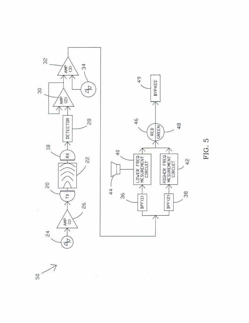
[0046] FIG. 5 is a functional block diagram for a battery
electrolyte level detector in accordance with the present
invention.
DETAILED DESCRIPTION OF THE INVENTION
[0047] Referring now to the drawings and, more particularly to
FIG. 1 and FIG. 2, there is shown an electrolyte level detector
10 mounted on across a cell 12 of a battery 14. The level
detector 10 can determine whether the battery 14 has lost water
due to evaporation and/or electrolysis by checking a battery
electrolyte level 16.
[0048] FIG. 5 depicts electronic functional elements 50 of the
level detector 10. These elements include an acoustic receiver
18 and a transmitter 20 which transmits an acoustic signal
through a medium 22, which may be either air or an electrolyte
within the battery 14. A wave generator 24 produces a signal to
be transmitted, which is amplified by an amplifier 26 and
transmitted by the transmitter 20 through the battery wall into
15

the medium 22. The receiver 18 receives the signal from the
medium 22 through the battery wall.
[0049] In this embodiment, a frequency differentiator section
is utilized to determine whether the sound waves traveled through
air or water. However, various circuits, known to those skilled
in the art, may be utilized to analyze frequencies, speed, and/or
wavelength to determine whether the signal traveled through air
or a fluid medium.
[0050] A detector 28 and an amplifier 30 produce an electrical
signal from sound waves and then amplify the detected signal. A
sinusoidal signal may be produced by a generator 34 and added to
the detected signal in an amplifier 32 to convert the signal to a
pulse width modulation signal. The pulse width modulation signal
is applied to two band pass filters 36 and 38, which block
unwanted signals and noise but pass either lower frequency
signals or higher frequency signals.
[0051] Lower frequency signals pass through the band pass
filter 36 and are detected at circuit 40. The circuit 40 drives
visual or auditory indicators that warn the operator that the
acoustic signal traveled through air, which is indicative of a
low level of electrolyte. The speed of sound in air is about 342
meters per second depending on ambient temperature. When the
circuit 40 recognizes that the signal passed through air, then
the circuit may activate an alarm such as piezoelectric speaker
44 and/or red LED 46.
16
[0052] Higher frequency signals are detected at a circuit 42
after passing through the band pass filter 38. The speed of
sound is water is approximately 1500 meters per second depending
on ambient temperature. The circuit 42 recognizes that the
waveform signal passes through water and may activate a green LED
48 or any other desired indicator to indicate that the
electrolyte level is acceptable. With that in mind, and
referring again to FIG. 1 and FIG. 2, the acoustic receiver 18
and the acoustic transmitter 20 are positioned on the sides of
the battery 14 at or just below the desired electrolyte level.
The acoustic receiver 18 and the acoustic transmitter 20 may be
adjusted to a precise level at the sides of the battery 14 by
utilizing micrometers 52 and 54. The micrometers 52 and 54 may be
constructed in various ways and may comprise commercially-
available micrometers.
[0053] Transmitter support rod 56 and receiver support rod 58
carry the transmitter 20 and the receiver 18, respectively. The
transmitter support rod 56 and the receiver support rod 58 are
slidable up and down to thereby position the transmitter 20 and
the receiver 18 at the desired height on the case of the battery
14 relevant to electrolyte level 16 within the battery 14. In
one embodiment, electronic micrometer readouts are utilized such
as electronic readout 60 (see FIG. 2) for the transmitter rod 56.
However, scales or the like may be inscribed on the transmitter
17
rod 56 and the receiver rod 58 for manual micrometer
measurements.
[0054] The micrometers 52 and 54 are preferably coated with
non-conductive material so as to avoid shock hazards. The
micrometers 52 and 54 are preferably slidably-mounted for
movement on pins 66 and 68 in slots 62 and 64 along rail members
76 to adjust to different size battery casings. Once the
micrometers are placed at the correct position in the slots 62
and 64; knobs or tightening means may be utilized with the pins
66 and 68 to threadably tighten or otherwise affix the
micrometers at the desired position. End retainers 98 and 100
may be utilized to secure the rail members 76. If desired,
bottom plate member 102 may be utilized to adapt to particular
battery shapes and/or provide additional support.
[0055] The micrometers 52 and 54 may also be pivotally mounted
on the pins 66 and 68, for stowing once an adjustment arm 70 is
removed. For example, once the adjustment arm 70 is removed,
and the electrolyte level detector 10 is removed from the battery
14, then the micrometers 52 and 54 may be mounted to pivot on the
pins 66 and 68 along the rail members 76 to a position parallel
with the rail members to provide a compact electrolyte level
detector in a stowed position.
[0056] The adjustment arm 70 may be utilized to simultaneously
move the transmitter support rod 56 and the receiver support rod

58 up and down. The user can check the micrometer readouts to
verify that both the transmitter 20 and the receiver 18 are at
the correct levels.
[0057] The desired electrolyte level for each battery type is
assumed to be known. In many batteries, it may only be necessary
to measure the electrolyte level at pilot cells, which may
typically be on the ends of the battery. The adjustment arm 70
may be removable for stowing the electrolyte level detector 10.
In this case, rod holders 72 and 74 may be designed to snap-fit
onto the adjustment arm 70 for stowage after the micrometers 52
and 54 are pivoted to the stowed position, as discussed above.
[0058] Grip 78 may be utilized to carry the electrolyte level
detector. The batteries for electronic circuit operation may be
mounted in the grip 78 and the electronics housed in cylinder 80.
The grip 78 may be removable. The LEDs 46 and 48 (shown in FIG.
5) and/or the piezoelectric speaker 44 may also be mounted in the
grip 78 or the cylinder 80.
[0059] FIG. 3 depicts an enlarged view of a preferred
transmitter 20 and receiver 18. In this embodiment, suitable
piezoelectric elements may be positioned along the transmitter
support rod 56 and the receiver support rod 58 at positions 84
and 86 in which the piezoelectric elements produce and/or receive
acoustic energy.
19

[0060] In this embodiment, relatively larger socket cups 90
and 92 adjacently connected to relatively smaller socket cups 94
and 96, respectively, comprise soft plastic material to thereby
form acoustic directors. The acoustic directors direct or
concentrate the acoustic energy over a relatively small point of
contact with the battery 14 for a more precise determination of
the location of the electrolyte level. The soft plastic material
tends to deaden transmission except through the larger and
smaller socket cups. Harder material may be positioned at the
contact region between the larger and smaller socket cups to
enhance acoustic transmission therebetween. Thus, acoustic
energy over the larger area of the relatively larger transmitter
socket cup 90 is transferred to a smaller region in the
relatively smaller socket cup 94.
[0061] Acoustic couplant such as jelly or other acoustically
conductive material 88 may be positioned in the relatively larger
socket cups 90 and 92. The relatively smaller socket cups 94 and
96 may be filled with jelly or other acoustically conductive
material including water for contact with the battery wall at the
time of testing. Various types of acoustic couplant materials
are commercially-available for this purpose. This acoustic
couplant jelly-like material may be added prior to measurement
and/or may be contained within a membrane.
[0062] The socket cups 90 and 92 have an additional function
in that they act as pin-point directors of acoustic energy to
20

more precisely determine the level of the electrolyte. All or
most of the acoustic energy is transmitted and received through
the socket cups 94 and 96. The socket cups 94 and 96 are
preferably less than one-quarter inch in diameter and may be less
than one-eighth of an inch in diameter. Thus, the level of the
electrolyte is determinable within less than one-quarter inch or
less than one-eighth inch.
[0063] FIG. 4 shows steps that may be utilized during
operation. As indicated at step 102, the battery 14 may be
cleared off or wiped down or cleaned on the outer surfaces for
testing. At step 104, the micrometers 52 and 54 are placed in a
vertical position and spaced apart in the slots 62 and 64 to fit
onto the battery 14. Knobs, such as the knobs 66 and 68 are
tightened, to secure the micrometers 52 and 54 in the desired
position in the slots 62 and 64 along the rails 76.
[0064] At step 106, an adjustment arm 70 may be utilized to
simultaneously move the transmitter support rod 56 and the
receiver support rod 58 up and down so that the transmitter 20
and receiver 18 are level with each other according to the
micrometers. At 108 and step 110, the operator insures that
electrolyte level detector 10 is inserted over the battery 14 at
the correct position for checking the electrolyte level of a
selected cell.
21

[0065] At steps 112 and 114, the arm 70 is utilized to adjust
the transmitter 20 and the receiver 18 up and down to the pre-
assigned position.
[0066] At step 116, if the green LED lights up, then the
battery check is completed as indicated at step 118. If desired,
the electrolyte level detector 10 can then be set to the stowed
position as indicated at step 121 by pivoting the micrometers to
a position which is level with rails 76 (See FIG. 2).
[0067] If the green light does not come on, then steps 120 and
122 are used to verify that the transmitter and receiver are
activated, such as by checking the on-off switch. If the red
light comes on at 124, then water is added at step 126. If the
red light is not on, then the procedure is repeated - as
indicated at step 128. If the red light comes on, as indicated
at 130, then water is added to the battery as indicated at step
126. If the green light comes on as per 134, then the test is
ended as indicated at 132. If at this time, neither the red
light nor the green light is on, then there may possibly be a
malfunction as indicated at step 136. This reguires checking on
procedures, acoustic coupling, the circuitry In FIG. 1 (a bypass
switch 49 is provided to ensure that any electrical eguipment
such as batteries or the LED 46 and 48 are operating properly),
and the like. Steps of adding electrolyte may be repeated as
necessary until the green light comes on. Because the battery
22
level can be quickly checked without opening the battery in many
cases, the present invention provides a safer and faster way of
checking electrolyte levels.
[0068] It will be understood that the electrolyte level
detector 10 can be modified in various ways. For example, in one
possible embodiment, the number of acoustic sensors may be
increased, such as by utilizing a wiring harness. The circuitry
for the acoustic sensors may be connected to a central computer
processor to analyze and monitor multiple batteries
simultaneously. Thus, monitoring can be either accomplished
remotely instead of through physical contacts.
[0069] In one possible example, if nine (9) batteries need to
be monitored, a three-by-three switchboard matrix with a wiring
harness connecting each electrolyte level detector could be
assembled. A two-way circuit, which allows each detector to be
selected via the switch matrix, would result in a red or green
light indication for each battery. If the color is red, water,
is needed, and if it is green, then no action is required.
[0070] In another embodiment, a single transducer positioned
on one side of the battery could perform the same task as the
receiver and transmitter discussed hereinbefore, but with a less
accuracy. In such a design, a return signal would be a
reverberation. To produce reverberation, an insulated metal
plate might be positioned opposite the transducer on the other
23

side of the battery. The frequency speed concept leads to the
same results, but as mentioned, the accuracy is degraded.
[0071] Many additional changes in the details, components,
steps, and organization of the system, herein described and
illustrated to explain the nature of the invention, may be made
by those skilled in the art within the principle and scope of the
invention. It is therefore understood that within the scope of
the appended claims, the invention may be practiced otherwise
than as specifically described.
24

Attorney Docket No. 99667
BATTERY ELECTROLYTE LEVEL DETECTOR APPARATUS
ABSTRACT OF THE DISCLOSURE
An electrolyte detector is provided that includes two
micrometers which slide relative to each other along a frame to
adjust the electrolyte detector to a size of the battery. A
transmitter rod and a receiver rod support an acoustic
transmitter and an acoustic receiver, respectively, and are
slidably mounted with respect to the micrometers. The
micrometers measure the position of the transmitter and receiver
for placement on the side of the battery at a desired level of
electrolyte. A transmitter director and receiver director
concentrates the transmission and receipt of acoustic energy to
locate the electrolyte level. An electronic circuit analyzes the
received signal to determine whether the signal is transmitted
through air or through an electrolyte.

o h—I

CN
6

CO
d (—1

OS w 2 H o w O
O
o E-
55 o a.
§ o H E- W oo CO
6 i—i
r OJ CD
4
2 o H
§g2 O > Q O 2 2
« a
7 o
cr^ ^ <A
(/) <L £L >- m
CO
d i—i
o in