2011 doe hydrogen program merit review · 2011-05-18 · 2011 doe hydrogen program merit review...
TRANSCRIPT

2011 DOE Hydrogen ProgramMerit Review
Development of a CentrifugalHydrogen Pipeline Gas Compressor
Mr. Francis Di Bella, P.E. and Dr. Colin OsborneConcepts NREC (CN)
May 10, 2010
Project ID#: PD017
This presentation does not contain any proprietary, confidential, or otherwise restricted information
2
Project Overview
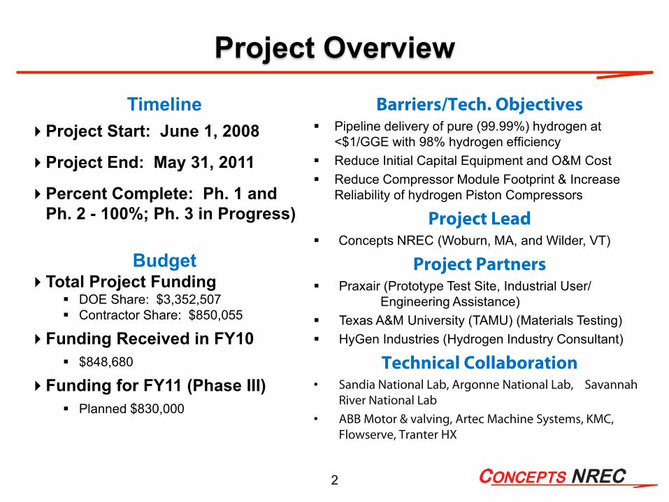
TimelineProject Start: June 1, 2008
Project End: May 31, 2011
Percent Complete: Ph. 1 and Ph. 2 - 100%; Ph. 3 in Progress)
BudgetTotal Project Funding
DOE Share: $3,352,507 Contractor Share: $850,055
Funding Received in FY10 $848,680
Funding for FY11 (Phase III) Planned $830,000
Barriers/Tech. Objectives Pipeline delivery of pure (99.99%) hydrogen at
<$1/GGE with 98% hydrogen efficiency Reduce Initial Capital Equipment and O&M Cost Reduce Compressor Module Footprint & Increase
Reliability of hydrogen Piston Compressors
Project Lead Concepts NREC (Woburn, MA, and Wilder, VT)
Project Partners Praxair (Prototype Test Site, Industrial User/
Engineering Assistance) Texas A&M University (TAMU) (Materials Testing) HyGen Industries (Hydrogen Industry Consultant)
Technical Collaboration• Sandia National Lab, Argonne National Lab, Savannah
River National Lab• ABB Motor & valving, Artec Machine Systems, KMC,
Flowserve, Tranter HX
3
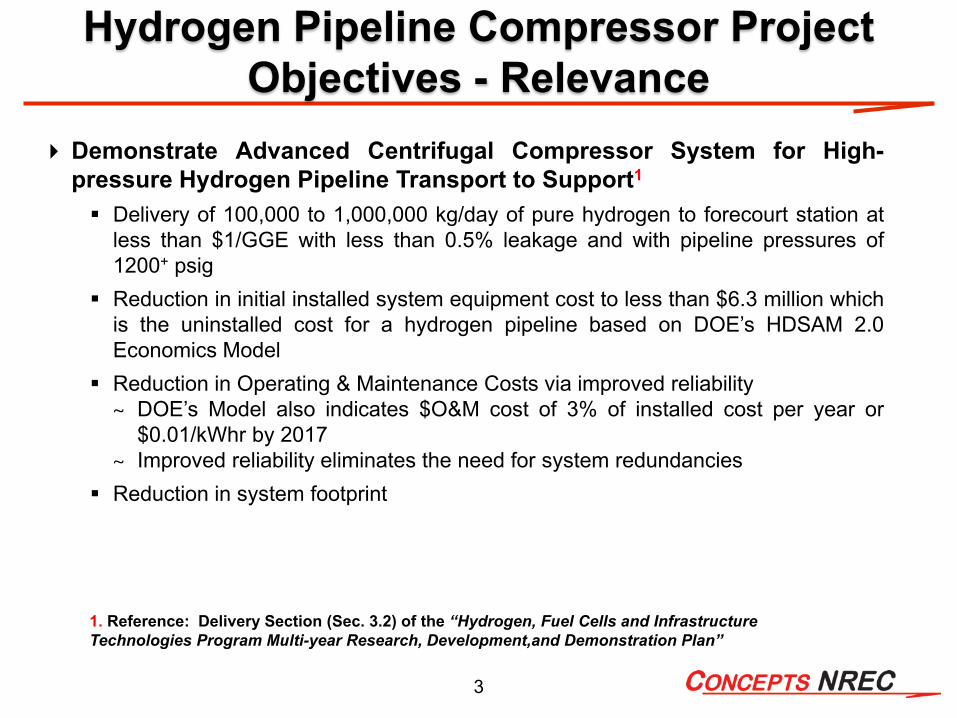
Demonstrate Advanced Centrifugal Compressor System for High-pressure Hydrogen Pipeline Transport to Support1
Delivery of 100,000 to 1,000,000 kg/day of pure hydrogen to forecourt station atless than $1/GGE with less than 0.5% leakage and with pipeline pressures of1200+ psig
Reduction in initial installed system equipment cost to less than $6.3 million whichis the uninstalled cost for a hydrogen pipeline based on DOE’s HDSAM 2.0Economics Model
Reduction in Operating & Maintenance Costs via improved reliability~ DOE’s Model also indicates $O&M cost of 3% of installed cost per year or
$0.01/kWhr by 2017~ Improved reliability eliminates the need for system redundancies
Reduction in system footprint
1. Reference: Delivery Section (Sec. 3.2) of the “Hydrogen, Fuel Cells and Infrastructure Technologies Program Multi-year Research, Development,and Demonstration Plan”
Hydrogen Pipeline Compressor Project Objectives - Relevance
4
Three-phase Program Approach
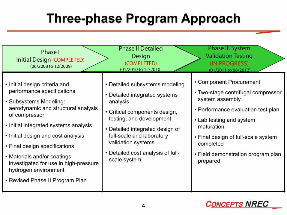
• Initial design criteria and performance specifications
• Subsystems Modeling: aerodynamic and structural analysis of compressor
• Initial integrated systems analysis
• Initial design and cost analysis
• Final design specifications
• Materials and/or coatings investigated for use in high-pressure hydrogen environment
• Revised Phase II Program Plan
• Detailed subsystems modeling
• Detailed integrated systems analysis
• Critical components design, testing, and development
• Detailed integrated design of full-scale and laboratory validation systems
• Detailed cost analysis of full-scale system
• Component Procurement
• Two-stage centrifugal compressor system assembly
• Performance evaluation test plan
• Lab testing and system maturation
• Final design of full-scale system completed
• Field demonstration program plan prepared
Phase I Initial Design (COMPLETED)
(06/2008 to 12/2009)
Phase II Detailed Design
(COMPLETED)(01/2010 to 12/2010)
Phase III SystemValidation Testing
(IN PROGRESS)(01/2011 to 08/2012)
5
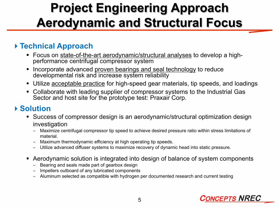
Technical Approach Focus on state-of-the-art aerodynamic/structural analyses to develop a high-
performance centrifugal compressor system Incorporate advanced proven bearings and seal technology to reduce
developmental risk and increase system reliability Utilize acceptable practice for high-speed gear materials, tip speeds, and loadings Collaborate with leading supplier of compressor systems to the Industrial Gas
Sector and host site for the prototype test: Praxair Corp.
Solution Success of compressor design is an aerodynamic/structural optimization design
investigation~ Maximize centrifugal compressor tip speed to achieve desired pressure ratio within stress limitations of
material.~ Maximum thermodynamic efficiency at high operating tip speeds.~ Utilize advanced diffuser systems to maximize recovery of dynamic head into static pressure.
Aerodynamic solution is integrated into design of balance of system components~ Bearing and seals made part of gearbox design~ Impellers outboard of any lubricated components~ Aluminum selected as compatible with hydrogen per documented research and current testing
Project Engineering Approach Aerodynamic and Structural Focus

6
Design Options for Alternative Operating Conditions
0
500
1000
1500
2000
2500
3000
3500
2 3 4 5 6 7 8PRESSURE RATIO
TIP
SPEE
D, F
T/SE
C
Industrial Machines
High Strength Alloys
Advanced Composites
No. Compressor Stages4
6
8
10121416
●Baseline Design PointDesired Pres. Range
Project Engineering Approach Operational Design Envelope
7
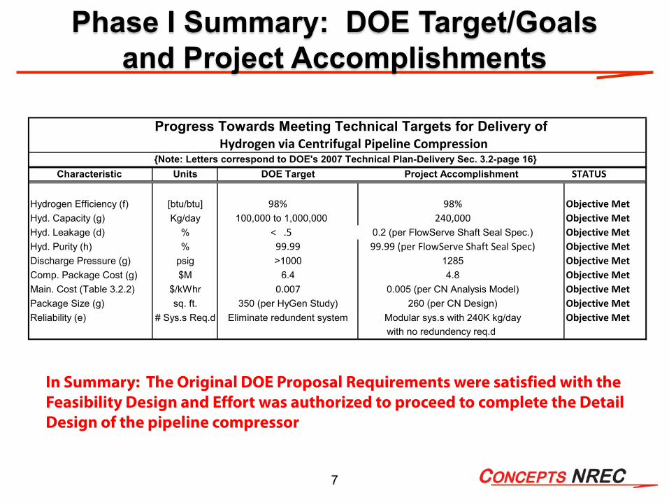
Phase I Summary: DOE Target/Goals and Project Accomplishments
Progress Towards Meeting Technical Targets for Delivery ofHydrogen via Centrifugal Pipeline Compression
{Note: Letters correspond to DOE's 2007 Technical Plan-Delivery Sec. 3.2-page 16}Units STATUS
Hydrogen Efficiency (f) [btu/btu] 98% 98% Objective MetHyd. Capacity (g) Kg/day 100,000 to 1,000,000 240,000 Objective MetHyd. Leakage (d) % < .5 0.2 (per FlowServe Shaft Seal Spec.) Objective MetHyd. Purity (h) % 99.99 (per FlowServe Shaft Seal Spec) Objective MetDischarge Pressure (g) psig 1285 Objective MetComp. Package Cost (g) $M 4.8 Objective MetMain. Cost (Table 3.2.2) $/kWhr 0.005 (per CN Analysis Model) Objective MetPackage Size (g) sq. ft. 260 (per CN Design) Objective MetReliability (e) # Sys.s Req.d Modular sys.s with 240K kg/day Objective Met
with no redundency req.d
350 (per HyGen Study)Eliminate redundent system
Characteristic DOE Target Project Accomplishment
99.99>1000
6.40.007
In Summary: The Original DOE Proposal Requirements were satisfied with the Feasibility Design and Effort was authorized to proceed to complete the Detail Design of the pipeline compressor
8
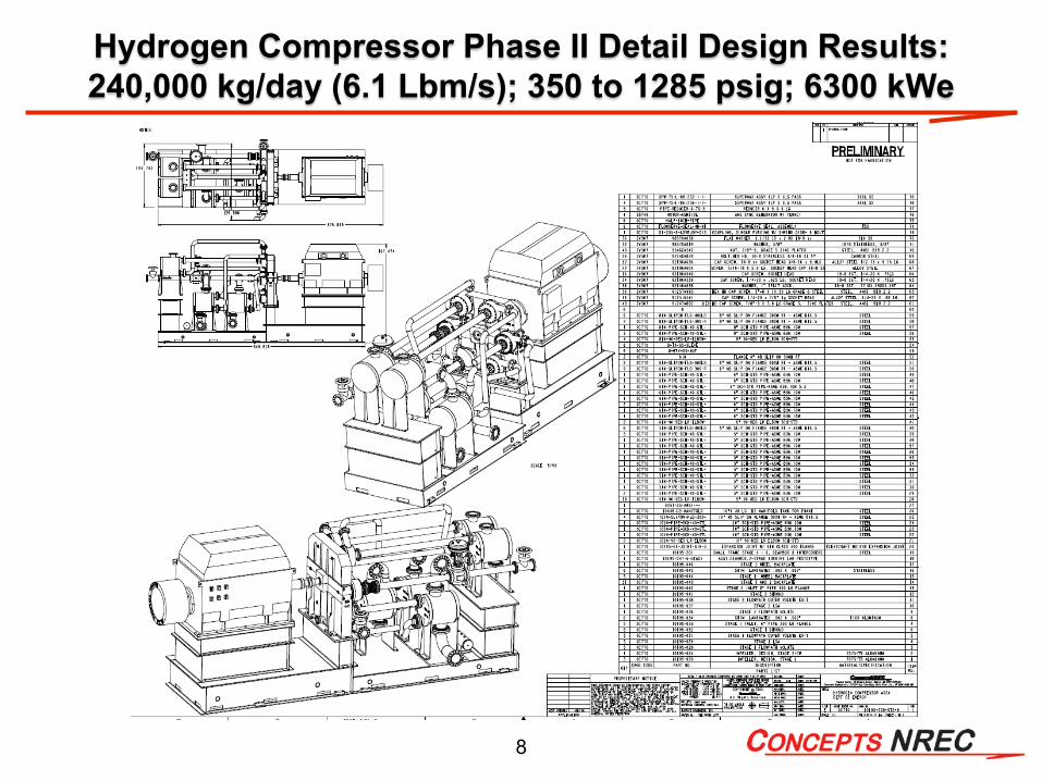
Hydrogen Compressor Phase II Detail Design Results: 240,000 kg/day (6.1 Lbm/s); 350 to 1285 psig; 6300 kWe

9
Phase II – Detailed Engineering Design for Six-stage Full-scale System and a Two-stage Laboratory Prototype
PHASE II OBJECTIVES:COMPLETED - Critical component
developed and/or specified for near-term availability (rotor, shaft seal, bearings, gearing, safety systems)COMPLETED - Detailed design and cost
analysis of a complete pipeline compressor systemCOMPLETED - A two-stage Laboratory
Prototype Compressor System to verify mechanical integrity of major components at full power per stageCOMPLETED - Go/No-Go decision regarding
proceeding into Phase III: Fabrication of Complete Two-stage Hydrogen Compressor for Laboratory Testing
10
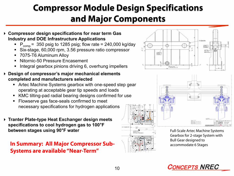
Compressor Module Design Specifications and Major Components
Compressor design specifications for near term Gas Industry and DOE Infrastructure Applications Pcomp.= 350 psig to 1285 psig; flow rate = 240,000 kg/day Six-stage, 60,000 rpm, 3.56 pressure ratio compressor 7075-T6 Aluminum Alloy Nitornic-50 Pressure Encasement Integral gearbox pinions driving 6, overhung impellers
Design of compressor’s major mechanical elements completed and manufacturers selected Artec Machine Systems gearbox with one-speed step gear
operating at acceptable gear tip speeds and loads KMC tilting-pad radial bearing designs confirmed for use Flowserve gas face-seals confirmed to meet
necessary specifications for hydrogen applications
Tranter Plate-type Heat Exchanger design meets specifications to cool hydrogen gas to 100°F between stages using 90°F water Full-Scale Artec Machine Systems
Gearbox for 2-stage System with Bull Gear designed to accommodate 6 StagesIn Summary: All Major Compressor Sub-
Systems are available “Near-Term”

11
Overlay of First and Sixth Stages for Size Comparison
Overhung Rotor-Drive Shaft Integrated with Shaft Seal, Bearing, and Pinion
Detailed Engineering Design for All Six Compressor Rotors Completed and First Stage Machined for Validation Spin Test
12
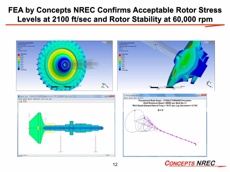
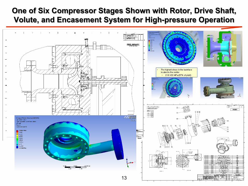
FEA by Concepts NREC Confirms Acceptable Rotor Stress Levels at 2100 ft/sec and Rotor Stability at 60,000 rpm
13
One of Six Compressor Stages Shown with Rotor, Drive Shaft, Volute, and Encasement System for High-pressure Operation

14
Major Focus of Phase II was Design of a Two-stage Laboratory Prototype for Testing in Phase III
15
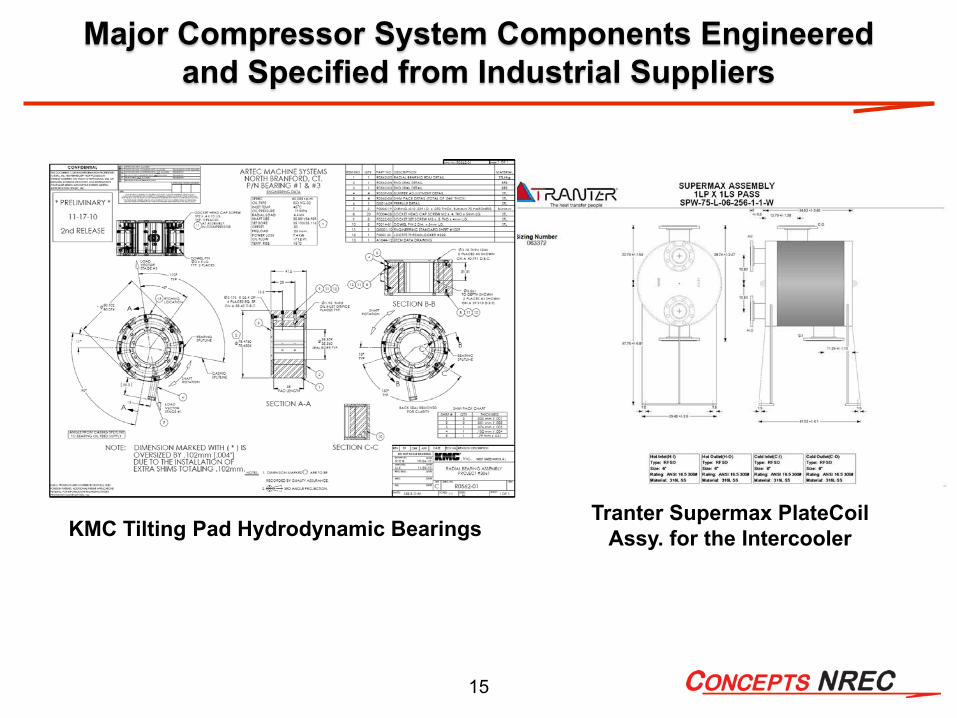
Major Compressor System Components Engineeredand Specified from Industrial Suppliers
Tranter Supermax PlateCoil Assy. for the IntercoolerKMC Tilting Pad Hydrodynamic Bearings

16
Major Compressor System Component High Speed Gas Shaft Seal
Flowserve Gas Shaft Seal is proven technology for use with hydrogen and provides acceptable performance and minimal leakage
60,000 rpm< 0.1% leakage
17
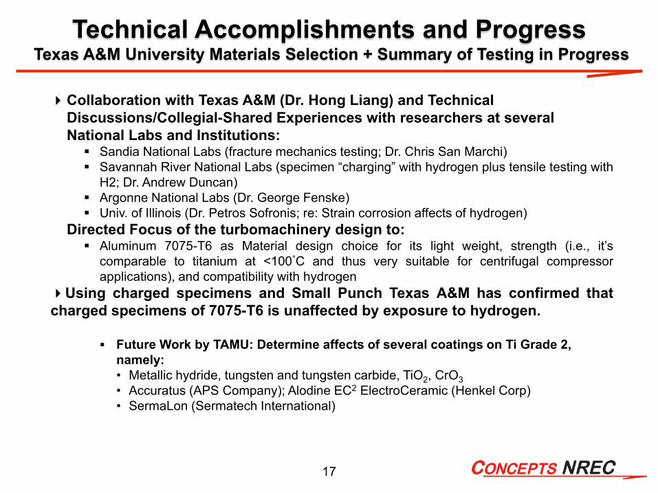
Technical Accomplishments and ProgressTexas A&M University Materials Selection + Summary of Testing in Progress
Collaboration with Texas A&M (Dr. Hong Liang) and Technical Discussions/Collegial-Shared Experiences with researchers at several National Labs and Institutions: Sandia National Labs (fracture mechanics testing; Dr. Chris San Marchi) Savannah River National Labs (specimen “charging” with hydrogen plus tensile testing with
H2; Dr. Andrew Duncan) Argonne National Labs (Dr. George Fenske) Univ. of Illinois (Dr. Petros Sofronis; re: Strain corrosion affects of hydrogen)
Directed Focus of the turbomachinery design to: Aluminum 7075-T6 as Material design choice for its light weight, strength (i.e., it’s
comparable to titanium at <100°C and thus very suitable for centrifugal compressorapplications), and compatibility with hydrogen
Using charged specimens and Small Punch Texas A&M has confirmed thatcharged specimens of 7075-T6 is unaffected by exposure to hydrogen.
Future Work by TAMU: Determine affects of several coatings on Ti Grade 2, namely:• Metallic hydride, tungsten and tungsten carbide, TiO2, CrO3• Accuratus (APS Company); Alodine EC2 ElectroCeramic (Henkel Corp)• SermaLon (Sermatech International)

18
Phase II Accomplishments within Schedule and Available Budget
Completed design of two-stage, full-load laboratory prototype
Completed development of computer performance & cost model
Completed FMEA analysis and analytical methodology to compare reliability and O&M costs of centrifugal and reciprocating compressors
Completed algorithm for anti-surge valve sizing for emergency shutdown and system venting strategy at start-up and shutdown
Comparative assessment of effects of hydrogen on aluminum and titanium specimens by Texas A&M University

19
Phase III System Validation Testing (Jan. 2011 to Sept. 2012) Continue materials testing at Texas A&M University with
hydrogen to determine affects of coatings that can be used with titanium
Component procurement for the two-stage functional hydrogen compressor system
Assembly of the two-stage centrifugal compressor system Coordinating integration of compressor prototype in a Praxair
hydrogen test facility Conduct aerodynamic testing and assessment of mechanical
integrity of the compressor system
Future Phase III Project Work
20
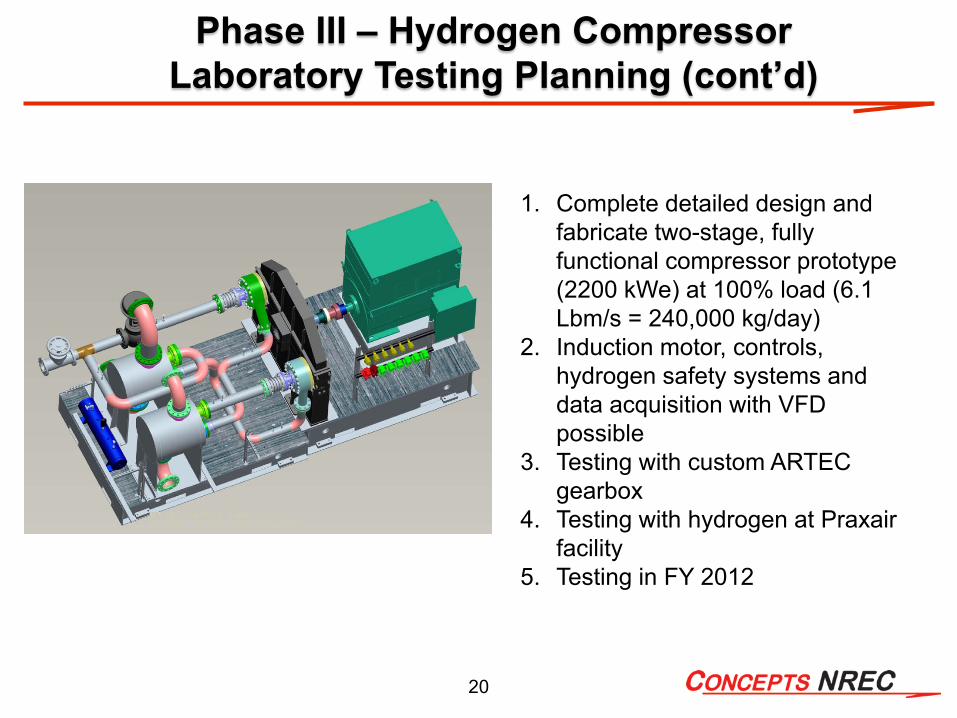
1. Complete detailed design and fabricate two-stage, fully functional compressor prototype (2200 kWe) at 100% load (6.1 Lbm/s = 240,000 kg/day)
2. Induction motor, controls, hydrogen safety systems and data acquisition with VFD possible
3. Testing with custom ARTEC gearbox
4. Testing with hydrogen at Praxair facility
5. Testing in FY 2012
Phase III – Hydrogen Compressor Laboratory Testing Planning (cont’d)
21
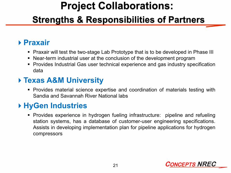
Project Collaborations:Strengths & Responsibilities of Partners
Praxair Praxair will test the two-stage Lab Prototype that is to be developed in Phase III Near-term industrial user at the conclusion of the development program Provides Industrial Gas user technical experience and gas industry specification
data
Texas A&M University Provides material science expertise and coordination of materials testing with
Sandia and Savannah River National labs
HyGen Industries Provides experience in hydrogen fueling infrastructure: pipeline and refueling
station systems, has a database of customer-user engineering specifications.Assists in developing implementation plan for pipeline applications for hydrogencompressors

22
Project SummaryRelevance: An advanced pipeline compressor system has been designed that meets DOE’s
performance goals for: High reliability with 350 to 1200+ psig compression of 240,000 kg/day at 98% hydrogen efficiency footprint 1/4 to 1/3 the size of existing industrial systems at projected cost of less than 80% of DOE’s
target
Approach: Utilize state-of-the-art and acceptable engineering practices to reduce developmentalrisk and provide a near-term solution for the design of a viable hydrogen pipeline compressor: aerodynamic/structural analyses for acceptable material (7075-T6 & Nitronic®-50) stresses in
hydrogen Industrially proven bearings, seal technology, gearing, heat exchangers, and lube system
Tech. Accomplishments & Progress: Aerodynamic analysis and design of a cost-effective, six-stage centrifugal compressor and a two-stage full-power lab prototype have been completed. Thetwo-stage laboratory prototype will be tested at Praxair’s facility.
Technology Transfer/Collaboration: The collaborative team consists of Praxair, an industrialtechnical experienced user and host of lab prototype test; a materials researcher, Texas A&M; ahydrogen refueling industry consultant, HyGen; and the coordinated technical support of severalNational Labs.
Proposed Future Research: Complete materials coating testing of specimens with TAMU; actualrotor forensics after high-speed testing; start the procurement of major components for thelaboratory testing of a two-stage prototype compressor-gearbox in Phase III; prepare Test Plan forlab test.
23
Additional Supportive Data
The following slides are included here to provide additional support during the question and answer period for the salient summary that has been offered during the formal presentation describing the extensive work that has been performed during the last 10 months.
25
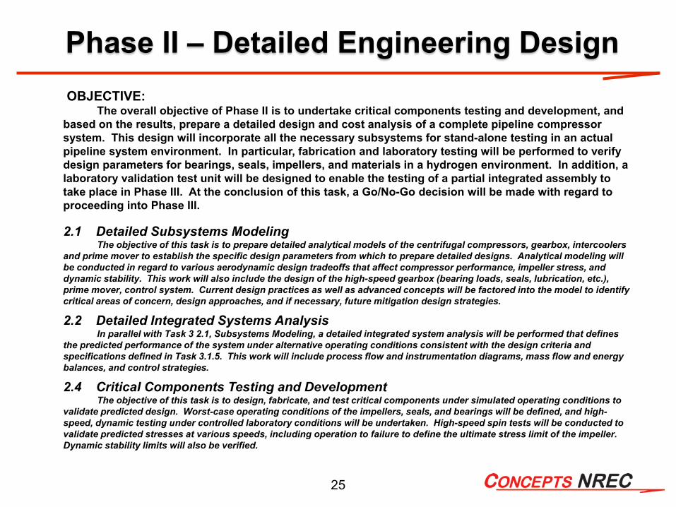
Phase II – Detailed Engineering DesignOBJECTIVE:
The overall objective of Phase II is to undertake critical components testing and development, and based on the results, prepare a detailed design and cost analysis of a complete pipeline compressor system. This design will incorporate all the necessary subsystems for stand-alone testing in an actual pipeline system environment. In particular, fabrication and laboratory testing will be performed to verify design parameters for bearings, seals, impellers, and materials in a hydrogen environment. In addition, a laboratory validation test unit will be designed to enable the testing of a partial integrated assembly to take place in Phase III. At the conclusion of this task, a Go/No-Go decision will be made with regard to proceeding into Phase III.
2.1 Detailed Subsystems ModelingThe objective of this task is to prepare detailed analytical models of the centrifugal compressors, gearbox, intercoolers
and prime mover to establish the specific design parameters from which to prepare detailed designs. Analytical modeling willbe conducted in regard to various aerodynamic design tradeoffs that affect compressor performance, impeller stress, and dynamic stability. This work will also include the design of the high-speed gearbox (bearing loads, seals, lubrication, etc.), prime mover, control system. Current design practices as well as advanced concepts will be factored into the model to identify critical areas of concern, design approaches, and if necessary, future mitigation design strategies.
2.2 Detailed Integrated Systems Analysis In parallel with Task 3 2.1, Subsystems Modeling, a detailed integrated system analysis will be performed that defines
the predicted performance of the system under alternative operating conditions consistent with the design criteria and specifications defined in Task 3.1.5. This work will include process flow and instrumentation diagrams, mass flow and energybalances, and control strategies.
2.4 Critical Components Testing and DevelopmentThe objective of this task is to design, fabricate, and test critical components under simulated operating conditions to
validate predicted design. Worst-case operating conditions of the impellers, seals, and bearings will be defined, and high-speed, dynamic testing under controlled laboratory conditions will be undertaken. High-speed spin tests will be conducted to validate predicted stresses at various speeds, including operation to failure to define the ultimate stress limit of the impeller. Dynamic stability limits will also be verified.
26
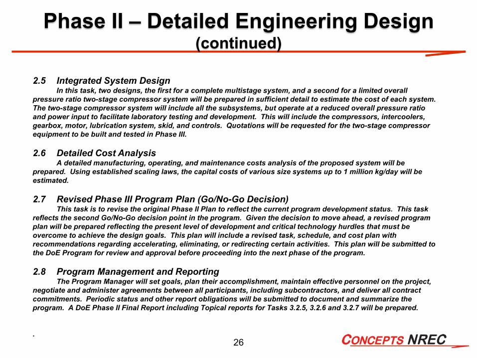
2.5 Integrated System DesignIn this task, two designs, the first for a complete multistage system, and a second for a limited overall
pressure ratio two-stage compressor system will be prepared in sufficient detail to estimate the cost of each system. The two-stage compressor system will include all the subsystems, but operate at a reduced overall pressure ratio and power input to facilitate laboratory testing and development. This will include the compressors, intercoolers, gearbox, motor, lubrication system, skid, and controls. Quotations will be requested for the two-stage compressor equipment to be built and tested in Phase III.
2.6 Detailed Cost AnalysisA detailed manufacturing, operating, and maintenance costs analysis of the proposed system will be
prepared. Using established scaling laws, the capital costs of various size systems up to 1 million kg/day will be estimated.
2.7 Revised Phase III Program Plan (Go/No-Go Decision)This task is to revise the original Phase II Plan to reflect the current program development status. This task
reflects the second Go/No-Go decision point in the program. Given the decision to move ahead, a revised program plan will be prepared reflecting the present level of development and critical technology hurdles that must be overcome to achieve the design goals. This plan will include a revised task, schedule, and cost plan with recommendations regarding accelerating, eliminating, or redirecting certain activities. This plan will be submitted to the DoE Program for review and approval before proceeding into the next phase of the program.
2.8 Program Management and ReportingThe Program Manager will set goals, plan their accomplishment, maintain effective personnel on the project,
negotiate and administer agreements between all participants, including subcontractors, and deliver all contract commitments. Periodic status and other report obligations will be submitted to document and summarize the program. A DoE Phase II Final Report including Topical reports for Tasks 3.2.5, 3.2.6 and 3.2.7 will be prepared.
.
Phase II – Detailed Engineering Design (continued)
27
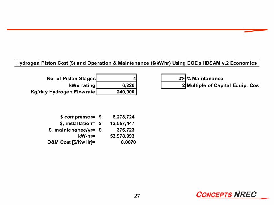
No. of Piston Stages 4 3% % MaintenancekWe rating 6,226 2 Multiple of Capital Equip. Cost
Kg/day Hydrogen Flowrate 240,000
$ compressor= 6,278,724$ $, installation= 12,557,447$
$, maintenance/yr= 376,723$ kW-hr= 53,978,993
O&M Cost [$/KwHr]= 0.0070
Hydrogen Piston Cost ($) and Operation & Maintenance ($/kWhr) Using DOE's HDSAM v.2 Economics

28
FMEA Document Has Been Prepared for Compressor
Subsystems ShownProject: DOE Hydrogen Compressor - Detail System: ARP
1 Motor Subsystem1.1 Motor Shaft1.2 Motor Bearings1.3 Motor Windings1.4 Motor Cooling2 Gearbox Subsystem
2.1 Low Speed (Input) Stage2.1.1 Input Coupling2.1.2 Input Shaft 2.1.3 Input Shaft Bearings2.1.4 Input Shaft Seal2.1.5 Input Gear2.2 Intermediate Speed Stage
2.2.1 Int. Gear (in)2.2.2 Int. Shaft2.2.3 Int. Bearings2.2.4 Int. Gear (out)2.3 High Speed (Output) Stage (2X)
2.3.1 High Speed Gears2.3.2 High Speed Shaft2.3.4 High Speed Bearings2.3.5 Thrust Bearing2.3.6 High Speed Shaft Seals2.4 Lubrication Subsystem
2.4.1 Lubricant2.4.2 Pump2.4.3 Filter2.4.4 Lubrication Jets
ID# Sub-Assembly / Component
FMEA Working Component List 3 Compressor Stages Subsystems3.1 Stage #1
3.1.1 Stage #1 Shaft3.1.2 Stage #1 Impeller3.1.3 Stage #1 Impeller Attachment3.1.4 Stage #1 Shaft Seal3.1.5 Stage #1 Housing3.2 Stage #23.3 Stage #33.4 Stage #43.5 Stage #53.6 Stage #6
4 Piping and Intercooling Subsystem
4.1 Piping4.1.1 Flanges / Seals4.1.2 Pipe4.2 Intercoolers
4.2.1 Flange / Seal, Working Fluid4.2.2 Flange / Seal, Coolant4.2.3 Internal Piping 4.2.4 Coolant
5 Hydrogen Containment Subsystem
5.1 Containment Housing5.2 HP Re-Introduction System5.3 LP Ventilation System6 System Skid7 Controls and Instrumentation

29
FMEA Document Risk Ranking Used with
Compressor Subsystems Shown
Failure Mode Identification and Risk Ranking
Project title:Author:Date:
Risk Matrix:Risk Level
LowMedium
High
No. Name
Indicative Annual Failure Rate
(up to)1 Very Low 1.0E-042 Low 1.0E-033 Medium 1.0E-024 High 1.0E-015 Very high 1.0E+00
Function Safety Environment Operation Assets
1
Minimal effect, easily repairable or redundant system
Negligible injury, effect on health
Negligible pollution or no effect on environment
Negligible effect on production (hours)
Negligible
2
Loss of redundant function, reduced capacity
Minor injuries, health effects
Minor pollution / slight effect on environment
Some small loss of production, less than a month
Significant, but repairable
3
Loss of parts of main function, with significant repairs required
Significant injuries and/or health effects
Limited levels of pollution, manageable / moderate effect on environment
Production loss of 1 month. Light intervention required to replace equipment
Localised damage, repairable on site
4
Shutdown of system A fatality, moderate injuries
Moderate pollution, with some clean-up costs / Serious effect on environment
Significant loss of production of 1 to 3 months
Loss of main function, major repair needed by removal of part of device
5
Complete failure Several fatalities, serious injuries
Major pollution event, with significant clean-up costs / disastrous effects on the environment
Total loss of production for more than 3 months
Loss of device
Prob. 1 2 3 4 55 Low Med High High High4 Low Low Med High High3 Low Low Med Med High2 Low Low Low Low Med1 Low Low Low Low Low
Detection Classes:
Detection Rating Description
5 Remote / Uncertainty
4 Remote
3 Low
2 Moderately High
1Very High/Almost Certain
Consequence
Consequence Classes:
Risk Categories
tolerable, no action requiredmitigation and improvement required to reduce risk to lownot acceptable: mitigation and improvement required to reduce risk to low
Event unlikely to occurNegligible event frequencyDescription
Design Controls will almost certainly detect a potential cause/mechanism and subsequent failure mode
Low to Moderate chance the Design Control will detect a potential cause/mechanism and subsequent failure modeModerately High to High chance the Design Control will detect a potential cause/mechanism and subsequent failure mode
DefinitionRemote chance Design Control will detect, or Design Control will not and/or cannot detect a potential cause/mechanism and subsequent failure mode; or there is no Design Control Remote chance the Design Control will detect a potential cause/mechanism and subsequent failure mode
10195 DOE Hydrogen Compressor - Preliminary DesignARP
Description of consequences (impact on)
Probability Classes:
Class
One or several events expected to occur each yearOne or several events expected to occur during the lifetimeEvent rarely expected to occur
Description

30
Example of Methodology for Comparing the Relative Maintenance Cost of a Piston and Centrifugal Hydrogen Compressor
31
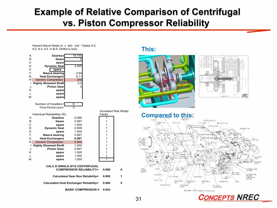
Example of Relative Comparison of Centrifugalvs. Piston Compressor Reliability
This:
Compared to this:
Hazard failure Rates (λ x e6): (ref.: Tables 9.2,9.3, 9.4, 9.5 in B.S. Dhillon's text)
A Gearbox 18.755B Gears 5C spareD Dynamic Seal 3.295E spareF Sleeve bearing 4.94G Heat Exchangers 6.11H Generic Compressor 200I Highly Stressed Shaft 0.2J Pinion Gear 5K spareL spareM spare
Number of Impellers= 6Time Period (yrs)= 3
Increased Risk MultiplIndividual Reliabilities (R): Factor
A Gearbox 0.990 1B Gears 0.997 1C spare 1.000 1D Dynamic Seal 0.998 1E spare 1.000 1F Sleeve bearing 0.997 1G Heat Exchangers 0.997 1H Generic Compressor 0.900 1I Highly Stressed Shaft 1.000 1J Pinion Gear 0.997 1K spare 1.000 1L spare 1.000 1M spare 1.000 1
CALC.D SINGLE-STG CENTRIFUGALCOMPRESSOR RELIABILITY= 0.990 6
Calculated Gear Box Reliability= 0.985 1
Calculated Heat Exchanger Reliability= 0.984 5
BASIC COMPRESSOR W 0.943
32
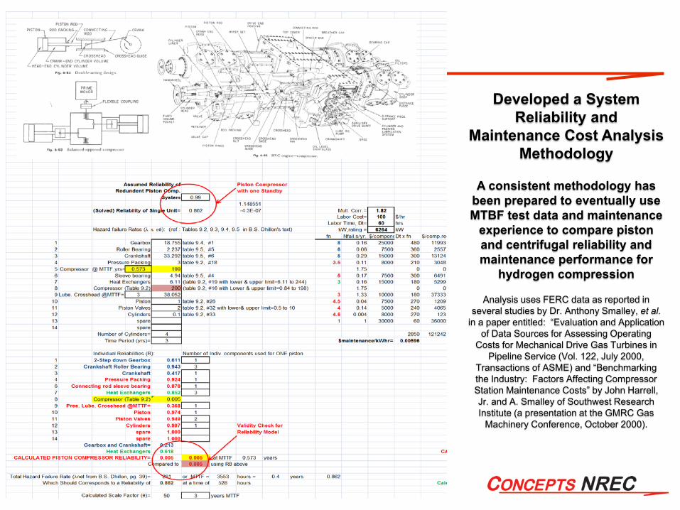
Developed a System Reliability and
Maintenance Cost Analysis Methodology
A consistent methodology has been prepared to eventually use MTBF test data and maintenance
experience to compare piston and centrifugal reliability and maintenance performance for
hydrogen compression
Analysis uses FERC data as reported in several studies by Dr. Anthony Smalley, et al.
in a paper entitled: “Evaluation and Application of Data Sources for Assessing Operating
Costs for Mechanical Drive Gas Turbines in Pipeline Service (Vol. 122, July 2000,
Transactions of ASME) and “Benchmarking the Industry: Factors Affecting Compressor Station Maintenance Costs” by John Harrell, Jr. and A. Smalley of Southwest Research Institute (a presentation at the GMRC Gas
Machinery Conference, October 2000).

33
Anti-Surge Control Model Algorithm for Emergency Shutdown
Enables the sizing of Anti-surge Control Valve and Downstream Piping
Pressure ratio & flow rate path of compressor as it almost exceeds surge control with valve Cv=42

34
General Piping and Instrumentation Flow Diagram for Hydrogen Compressor System

35
Design Experience Associating Material Properties with Tip Speed of 2200 ft/s with Aluminum Alloy - 2
Literature Survey (Rocketdyne Lab Tests for NASA) and reviews with materials researchers at national labs and private consultants indicate Aluminum Alloy shows no effect from hydrogen …. AND aluminum is an excellent structural material for high-speed impellers based on specific strength (ultimate strength/density)

36
Project Objectives – Relevance to DOE Hydrogen Economy Planning
DOE-stated Technical Barriers and Objectives to Establishing Hydrogen as Viable Alt. Fuel as expressed in the Delivery (Section 3.2) of the “Hydrogen, Fuel Cells and Infrastructure Technologies Program Multi-year Research, Development and Demonstration Plan”Develop and demonstrate an advanced centrifugal compressor system for
high-pressure hydrogen pipeline transport to support DOE’s strategic hydrogen economy infrastructure plan
Deliver 100,000 to 1,000,000 kg/day of 99.99% hydrogen gas from generation site(s) to forecourt stations
Compress from 350 psig to 1,000 psig or greaterReduce initial installed system equipment cost to less than $9M (Compressor
Package of $5.4M) for 200,000 kg/day system by FY 2017Reduce package footprint and improve packaging design Achieve transport delivery costs below $1/GGEReduce maintenance cost to below 3% of Total Capital Investment by FY 2017 Increase system reliability and thus avoid purchasing redundant systemsMaintain hydrogen efficiency (as defined by DOE) to 98% or greaterReduce H2 Leakage to less than 0.5% by FY 2017

37
Mechanical Detail of Compressor Stage All Stages Have the Same Mechanical Design
38
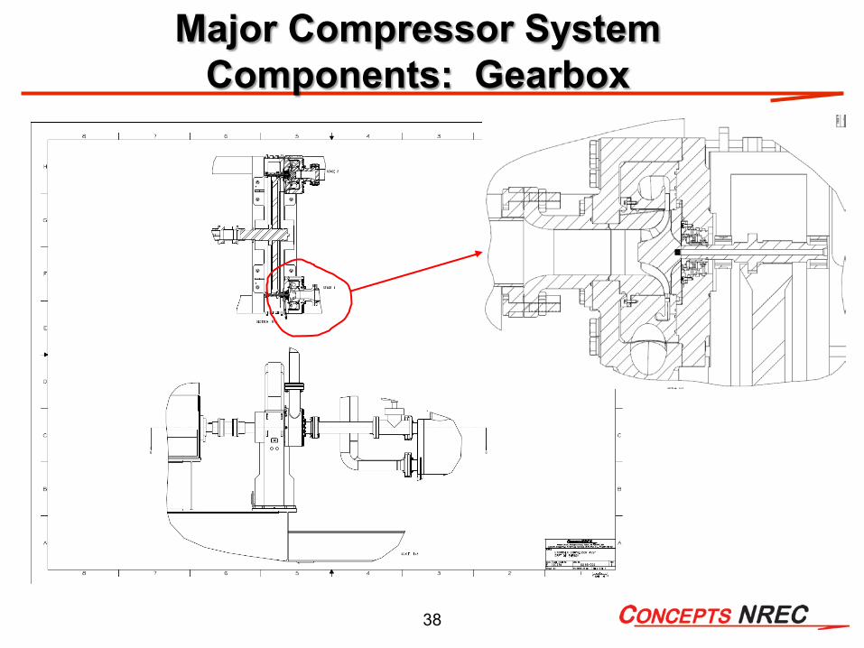
Major Compressor System Components: Gearbox
39
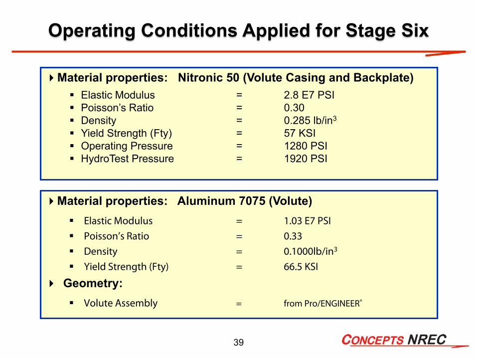
Operating Conditions Applied for Stage Six
Material properties: Nitronic 50 (Volute Casing and Backplate) Elastic Modulus = 2.8 E7 PSI Poisson’s Ratio = 0.30 Density = 0.285 lb/in3
Yield Strength (Fty) = 57 KSI Operating Pressure = 1280 PSI HydroTest Pressure = 1920 PSI
Material properties: Aluminum 7075 (Volute) Elastic Modulus = 1.03 E7 PSI Poisson’s Ratio = 0.33 Density = 0.1000lb/in3
Yield Strength (Fty) = 66.5 KSI
Geometry: Volute Assembly = from Pro/ENGINEER®
40
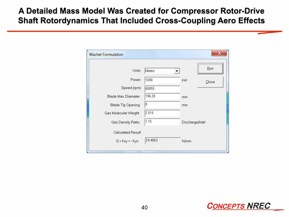
A Detailed Mass Model Was Created for Compressor Rotor-Drive Shaft Rotordynamics That Included Cross-Coupling Aero Effects

41
Specially machined fixture for small hole punch testing of metal specimens for project
tests at speeds of 0.0021 mm/s
The following figures have been reproduced from the three technical papers that have used the technique to test materials.
Sources:
1. Klevtsov, I., “Using Small Punch Test for Determination of Tensile Properties of Steel,” 6th International DAAAM Baltic Conference, April 2008.
2. Song, S. H. et al.,” Small Punch Test Evaluation of Neutron-Irradiation-Induced Embrittlement of a Cr-Mo Low-Alloy Steel,” ELSEVIER, 53: 35-41, 2004.
3. Lee, J., et al., “Application of Small Punch Test to Evaluate Sigma-Phase Embrittlement of Pressure Vessel Cladding Material,” Journal of Nuclear Science and Technology, 40( 9): 664-671, 2003.
Small Punch Test Apparatus by TAMUto Determine Effects of Hydrogen Exposure

42
0 0.1 0.2 0.3 0.4 0.5 0.6 0.70
200
400
600
800
1000Ti Grade 5 Gas Charged
Extension [mm]
Forc
e [N
]
Embrittled12 hrs exposed600 hrs exposedNormal
Actual Test Result with Ti Grade 5 showing degradation of strength in hydrogen over time
0 0.1 0.2 0.3 0.4 0.5 0.6 0.70
100
200
300
400
500
600
700
800
900
Extension [mm]
Forc
e [N
]
UnchargedCharged
3003-H14 aluminum
Ti-6Al-4V
Home-made H charge system, soaking samples in a H2 containing reservoir.
Force vs. Extension curve showing how the mechanical strength of theTi-6Al-4V specimens changes over time
at room temp. after charging BUT Aluminum specimens are not affected
Summary Details of Small Punch Test by TAMU
43
0 0.2 0.4 0.6 0.8 10
100
200
300
400
500
600Al 7075 Gas Charged
Extension [mm]
Forc
e [N
]
E1E2E3E4E5E6E7E8E9E10E11E12Normal
0 0.2 0.4 0.60
100
200
300
400
500
Extension [mm]
For
ce [N
]
AverageDeviationAverage Normal
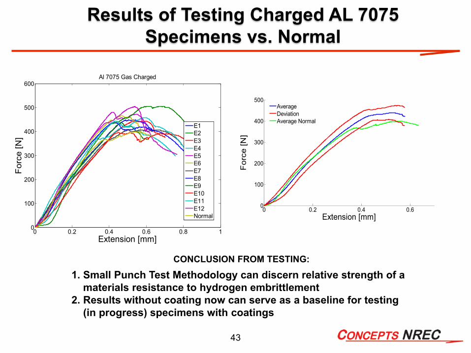
CONCLUSION FROM TESTING:
1. Small Punch Test Methodology can discern relative strength of a materials resistance to hydrogen embrittlement
2. Results without coating now can serve as a baseline for testing (in progress) specimens with coatings
Results of Testing Charged AL 7075 Specimens vs. Normal