2011 social media emergency management camp
TRANSCRIPT
1
Lasers from Islamabad
The LHC at CERN
and
Lahore
What Binds them Together
Shaukat Hameed Khan
13 May, 2010
Celebrating 50 Years of the Laser
1

2
The Laser is 50 on 16th May 2010.
• Will discuss:• A small Pakistani contribution to the design of the
system which makes up the massive detectors in the Large Hadron Collidor at CERN in Geneva.
• Context of mankind’s greater quest over the centuries for precision, whether these relate to his position on earth or in space, or timekeeping.
• Role of Qaim Mohammad of Lahore
• Will present the principal features of the laser programme in Pakistan.
2

3
Tribute to the Laser Pioneers
• The Laser should have been ‘discovered’ / built in the 1930s. All the theoretical constructs were in place.
– Einstein …. Spontaneous and Stimulated emissions– Quantisation of Blackbody Radiation– Gaseous discharges, crystallography, optics, etc
• Recognition? Professor vs Post-Doc
– Townes & Schawlow: Maser’s optical equivalent at Bell Labs. • Primary interest: Continuous laser for spectroscopic studies –
not pulsed - could not use ruby as the lasing medium.
– Maiman’s breakthrough, 1960 : Pulses of coherent light from a small ruby rod illuminated by a flash lamp.
– Initially a cinema projector lamp
3

4
SOURCES OF LIGHT
NaturalLight
Cd M2
ManmadeLight
Lasers
Normal Vision
SunHor. Zen.Night
SkyDark Clear Sky
Sky
10-6 10 -2 10 +2 10+6 10+10
1Km 1 m 1 µm 1 AO 1 X-ray Unit
1014 1010 106 102 10-2 10-6 10-10
Wavelength: IR 7000 Ao 4000 Ao UV
(Microns)
The EM Spectrum
4

5
SNo
Source Power(Watts)
EmittingArea
(cm 2 )
EmittingSolidAngle
Ω
BW/cm2/
Ω
1 Sun 4*10 26 2.5*1023 4 Π ~ 130
2 MercuryArc Lamp
104 ~ 1.0 4 Π ~ 800
3 Laser Diode Pointer
10- 3 ~ 0.1 10 - 6 ~ 10 4
4 Nd : Yag( LRF )
1* 10 6 ~ 0.1 10 - 6 10 13
5 Nd : Glass( Fusion)
2*10 13-15 4*103 5*10 – 8 10 25
Brightness: Power / unit area / solid angle / unit λ
5

6
Basically Three Types
DiagnostcTool
MetrologyAnalysisNDTFusionSensor/Probe
Change Agent Carrier
Material Working
Cut, Drill Weld
Surgery
Photochemistry
Communications
Controls/Guidance
Military Applications• Laser
Rangefinders• PGM’s• Weapon• Secure Comm
Laser Applications

77
Some ApplicationsIndustry:o Welding of auto chassis, hermetic sealing of ICso Microdrilling, Cutting, Ablationo Photolithographyo Rapid Prototyping, Stereolithography (photo - polymers)
Medicineo Optical Coherence Tomography (laser ultrasound, under the tissue).o Photo dynamic therapy
Astronomy / Astrophysicso Giant Interferometers ( LIGO) - gravitational waves - precision < proton sizeo ‘Guide’ stars –Induced Fl., Na, 93Km - Adaptive optics of ground telescopes
Research: endless applicationso Optical tweezers – hold & manipulate μscopic particles – bacteria o Laser cooled atoms – Optical molasses – Atomic clockso Slow light o Quantum Computingo Fusion / Simulation of Nuclear Weapons
Communication, Entertainment ……….Defence……..

88
Lasik, Moulding of the cornea
Guide star, 30 m telescope. 10x of Hubble
fsec photo-graphy
OCT of fingertip 1974 1982 1990 1998
2006
Argus
Shiva, 1X beam
Nova (single beam)
T3, Univ. of Rochester
10 TW Nova
LLNL, 100 TW, Nd laser
LLNL 1.25 Petawatt Nd laser
CEA Limeil
Rutherford Vulcan CPA
Long Pulse Technology
Early Lasers
Chirped pulse Amplifucation
NIF single beam
1,000
100
10
1
Peak
Las
er P
ower
, TW
NovaNIF
107
105
103
102
101
Joul
es
1970 1980 1990 2000 2010 Year
DPSSL

9
Can we measure this slowing down ?
LASER RANGE FINDERS & LONG BASE INTERFEROMETRY ( lunar and satellite ranging); + GPS. ( < 0.01 msec )
9
The Longest Day Last in the last 100 Years:: During 1912.The shortest day : August 2, 2001, > by 1 msec<
(Geophysicist Dr. Richard Gross.JPL)
LASER RANGING: Airborne lidar system
finds hidden fault lines
AA 3Laser Altimeter,
Accurate estimate of the position of the center of the moon:
Of paramount importance in mapping out the position and orbit and specially for studying the moon’s liquid core and testing ideas about gravity
April 22, Murphy et al UCSD/NASA ; laser pulses, the 3.5 m telescope at the Apache Point Observatory in New Mexico, found the Lunokhod 1 reflector and pinpointed its distance from earth to within 10 mm
10
10
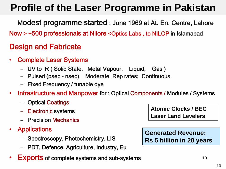
Profile of the Laser Programme in PakistanModest programme started : June 1969 at At. En. Centre, Lahore
Now > ~500 professionals at Nilore <Optics Labs , to NILOP in Islamabad
Design and Fabricate• Complete Laser Systems
– UV to IR ( Solid State, Metal Vapour, Liquid, Gas )– Pulsed (psec - nsec), Moderate Rep rates; Continuous– Fixed Frequency / tunable dye
• Infrastructure and Manpower for : Optical Components / Modules / Systems– Optical Coatings– Electronic systems– Precision Mechanics
• Applications– Spectroscopy, Photochemistry, LIS– PDT, Defence, Agriculture, Industry, Eu
• Exports of complete systems and sub-systems
Atomic Clocks / BECLaser Land Levelers
Generated Revenue:Rs 5 billion in 20 years

11
Some Tributes / Some Names# Year Laser Group/ Optics Labs Others1 1969 Dr S.H. Khan, Dr. Aijaz karim
QAU1975 – 1980Dr. M. S. Razmi, Dr. G. Murtaza
1980-1990Dr. M.S. Zubairi, Dr. M. Aslam Baig
2008Dr. Khurshid Hasnain
2 1970 - 78
Dr. Nisar Ahmad; Dr Sh. ShahdinDr Qaisar Sultana;
Dr. Aslam Khan Dr. Ehsan Khawaja;
1975-85
Dr. Khalid RashidDr. Iqbal SiddiquiDr. Sarfaraz BhattiDr. Javed AkhtarDr. Badar SulemanDr. Masroor Ikram
Mr. Amjad ParvezMr. M. IqbalMr. Maqbool Ch.Mr. Afzal ChaudhryMr Shahid ButtMr Imtiaz Ahmad
3 1985-2010
Dr. M.S. FarooqiDr. M. NawazDr. A. FarooqDr. M ArshadDr. Ramiz ul IslamDr. M AtifDr. ShamraizFirdousDr M. Saleem
Dr. Ghazanfar HussainDr. M AslamDr Mushtaq AhmedDr. Zulfiqar AliDr. Abid AliDr. Jahanzeb ShahDr. Khalid MehmoodDr. Iqtidar Shakoor
Comsats IIT, Islamabad2006-
3 PhDs, led by Dr. Aslam Khan

12
Down Memory Lane
12
Nathiagali, 1976, with Prof Kastler
Islamabad, 2006; with C.H. Townes

13
Some Current Laser Research
1. Atomic and Molecular Spectroscopy2. Building a Cesium Atomic Beam Clock at NILOP
A. Global Accuracy ~ 10-12; Short Term Stability ~ 10-10. B. MOTs (Total Electron Impact XSection on Cs)C. BEC … Free Expanding Cloud of Cold atoms as an Atomic
Standard: Ramsey Fringe Contrast . Initial stages3. PDT4. GaN. MBE with In-situ ellipsometeric Studies; RHEED (Reflection
High Energy Electron Diffraction)5. Laser Assisted Ablation/Deposition, Diamond like films6. LIDAR7. Nano Magnetic Films by Laser Ablation
13

14
Epitaxial Growth Laboratory• MBE with In-situ ellipsometer; Reflection High Energy Electron Diffraction
Lithography Laboratory
• Spin Rinse dryer; Oxygen Plasma Stripper, Spin Coater, Mask Aligner
• Developer Station; Inspection Microscope; Surface Profiler
• Acid Wet Bench; ICP/RIE System
• E-beam System; Dicing Saw, Probe Station; Wire Bonder
Lapping and Polishing Laboratory
• Interferometer, Microscope, Diamond Cutting Machine
PVD Laboratory RF/DC Sputtering; Thermal/Electron beam evaporation; PLD
Characterization Laboratories Ellipsometer; Spectrophotometer; FTIR; Scan. Probe /Tunnel. μscope; Photo/Electroluminescence/Raman spectroscopy
Simulation and Designing Laboratories LaserMod software
14

1515
Comparative study of Group II-B elements
42930 42960 42990 43020 43050 43080
100
200
300
400
500
+
+
18d3 D
1
24s3 S
117
d3 D1
16d3 D
1
21s3 S
1
25s3 S
1
25d3 D
2
Ioni
zaio
n en
ergy
(arb
.uni
ts)
Laser energy cm-1
19d3 D
2
27s3 S
1
+173 S
1
72225 72250 72275 72300 72325 72350 72375
200
300
400
500
600
700
800
900
23d1 D 2
27d3D2
23d3D2
481nm
27s3 S 1
Ioni
zatio
n Si
gnal
(arb
.uni
ts)
Term Energy cm-1
23s3 S 1
480nm
21d3D221
d1 D 2
6s6p3P1
6s2 1S0
λ1= 253.7nm
84184.1 cm-1
λscan=247-223 nm
41580 41610 41640 41670 41700
200
300
400
500
600
700
800
900
23d1 D 2
21d1 D 2
23s3 S 1
27s3 S 1
21d3 D 2
23d3 D 2
Ioniza
tion S
ignal(
arb.un
its)
Laser Energy cm-1
27d3 D 2
Published in Eur. Phys. J. D 53, 147 (2009).

1616
PLD
Dye LaserYAG for CERN
TEA CO2 Laser
Some Infrastructure
Optical Fabrication
Tea N2 Laser

17
1.
Laser Range Finder, AR 3
2.
Tank Range Finder; Models TR 2, TR 3
3.
Tank Driver’s Night Sights, DNS 3
AA 3Laser Altimeter,
4. 5. 6.
Hand-held Thermal Camera
8.7. 9.
Defence Products
ARS 134Airborne Radio
Tank Gunner Thermal camera
Replacement, LRF, T-80 UDTI Test Bench
EU 9.7 m contract

18
LDR 3 Laser Designator
Day / Night Surveillance System
INU Calibration JigHUD Combiners
Conventional Systems for Defence
Laser Land Leveler
• 30% less water• Higher yields• Prevents
waterlogging & salinity
10. 12.
13.
11.
14.

19 19
Optics Labs and CERN: A Chance Encounter , 1989
• A CERN team was visiting PINSTECH in Sep. 1989. • Looking for partners : design and fabricate parts and modules for
the massive CMS Detector (LHC) at CERN• Spare time, unscheduled visit to Optics Labs next door.....
Only dedicated / integrated Laser Lab in Pakistan:
Clear expertise : optics, lasers, electronics precision mechanics Excellent infrastructure:
Optics Lab and its precursor – the Laser Group at Pinstech involved in research , teaching, and production for over 36 years.
A natural partner for CERN.

20 20
Includes 40 laser based Position Monitoring Modules
From Optics Labs, Pakistan.
2007: The Loaded Tracker Unit being Placed inside CMS.
Laser Research in Pakistan and CERN

2121
FOUR MAJOR CONTRIBUTIONS of PAEC* to CERN:
Transporter ~ 13 T
CMS Magnet Feet, ~ 28 T
1. Magnet Feet for CMS (Fabrication only)
2. Resistive Plate Chambers ( Assembe / Test)
3. Assembly and Test of Carbon Frames and RODS for TOBs
4. Laser Based Position Monitoring System for Tracker of CMS (design, fabrication, installation)
5. Part of Int. Data Processing - GRID
2222
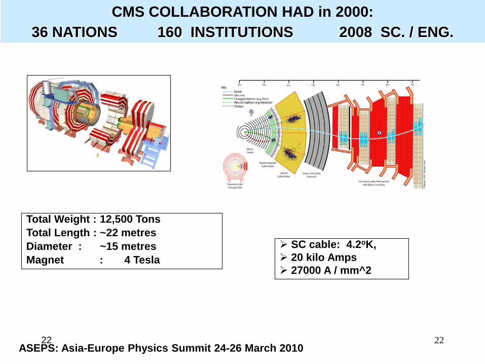
CMS COLLABORATION HAD in 2000: 36 NATIONS 160 INSTITUTIONS 2008 SC. / ENG.
Total Weight : 12,500 TonsTotal Length : ~22 metresDiameter : ~15 metresMagnet : 4 Tesla
SC cable: 4.2oK, 20 kilo Amps 27000 A / mm^2
ASEPS: Asia-Europe Physics Summit 24-26 March 2010

2323
Main Purpose of CMS: p-p detector > Study physics underlying breakdown in the electroweak symmetry:Several possibilities: Higgs mechanism favoured in the context of Supersymmetry. BUT, Need to cleanly detect “signatures”
… photons, muons, electrons jets … over large energy range and large luminosities
CMS is Optimised for search of : Higgs Boson ; CP violations; Top Quark Studies; Onset of Quark Gluon Plasma Formation
Luminosities ≥ 1034 cm-2 s-1; Magnet 4 T, crystal e.m. calorimeter, powerful inner tracker
Leads to precisions of < 1% at 100 GeV
The CMS Challenge

2424
Depends as much on Intrinsic Detector Capability Stability of the Structure ( Design… Materials …
Stiffness / Stability )
Expected Movements Of The Assembled Structure ? Very Very Heavy /Large StructureWill Move and Distort Due to:
Gravity, Magnetic field, Temperature Gradients, Differential Expansions ( e.g, Si, Steel, Al , CF, quartz) ,
Even Affected by the Water Level In Lake Geneva
Shifts /distortions up to 20 mm !
Optics Labs Focussed on the CMS TrackerTracker Performance: Heart of The CMS
2525
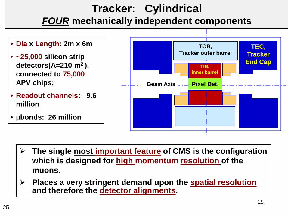
• Dia x Length: 2m x 6m
• ~25,000 silicon strip detectors(A=210 m2 ), connected to 75,000APV chips;
• Readout channels: 9.6 million
• µbonds: 26 million
Tracker: Cylindrical FOUR mechanically independent components
The single most important feature of CMS is the configuration which is designed for high momentum resolution of the muons.
Places a very stringent demand upon the spatial resolutionand therefore the detector alignments.
TEC, Tracker End Cap
Beam Axis Pixel Det.
TIB, inner barrel
TOB, Tracker outer barrel

26
X1,y1
Need to know where the detectors are w.r.t each other
X2,y2
Muon Momentum related to bending in transverse plane
Rad. of curvature ρ(m) = pt GeV/c / 0.3 BT. ρ ~d2/8s‘s’: muon trajectory sagita after travelling distance ‘d’
Error in s > error in muon measurement.
δs/s = δp/p α σs (mm) pt (TeV) / d2 (m2) B (T)26
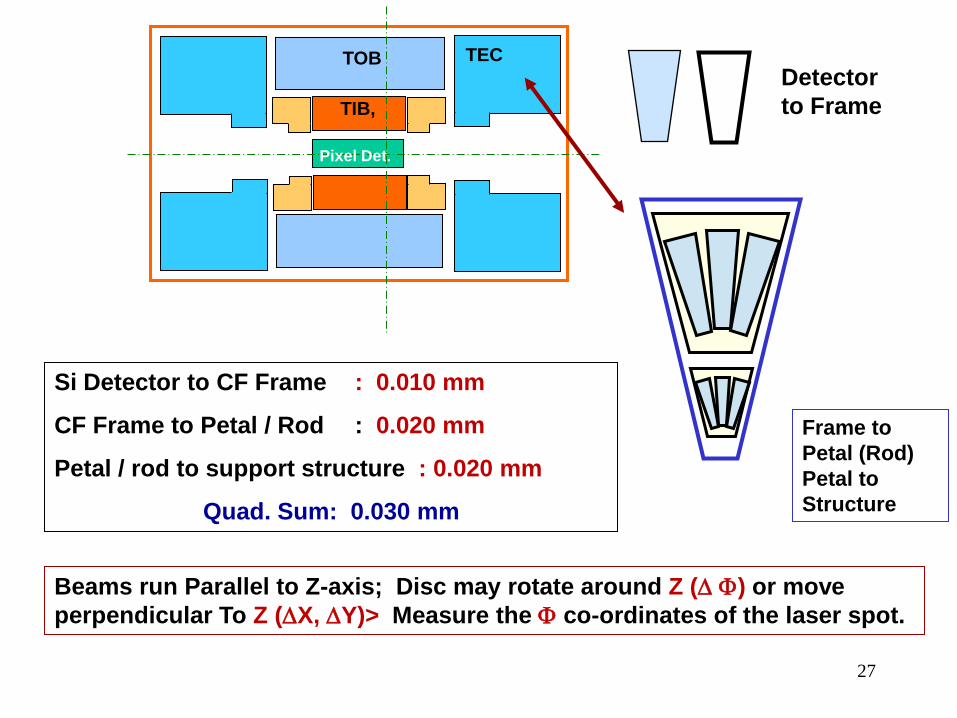
27
TIB,
TECTOB
Pixel Det.
Frame to Petal (Rod) Petal to Structure
Si Detector to CF Frame : 0.010 mm
CF Frame to Petal / Rod : 0.020 mm
Petal / rod to support structure : 0.020 mm
Quad. Sum: 0.030 mm
Detector to Frame
Beams run Parallel to Z-axis; Disc may rotate around Z (∆ Φ) or move perpendicular To Z (∆X, ∆Y)> Measure the Φ co-ordinates of the laser spot.

28
TRACKER: Required Precision
X
Y
X
Y
Z
Vertical Position
R ( µm)
R - φ( µm)
Z ( µm)
200 mm 100 15 500
700 mm 300 15 500
1200 mm 600 50 2000
Max. distortion @ R=1200 mm: - 0.314 mm at top
28

2929
Key Features of the Position Monitoring SystemThe laser pulse produces photo-electrons in the silicon detector
Also transmitted to other detectors if correct λ.
The same electronic systemreads out the signal from the high energy particles as well as the laser beam.
Only a few tens of fCof charge to be produced to avoid saturation
λ=1064 nm
Response curve, Si
Transmission Curve of Si
T~30%~0.2A/W

3030
Laser passes through successive detectors:
Read the signal / laser position (c.o.g.) from each detector
One shot gives many relative positions of many detectors at the same instant
Repeat sequence
Read the Laser Centre of Gravity (COG)
Diffraction from Detector strips
Less coherent diode laser
Laser COG Profile

3131
250
200
150
100
50
0
269.6 269.8 270.0 270.2 270.4
Some Data
The C.O.G. Resolution :
0.2 µm in X ; 0.3 µm in Y

3232
Searching for Laser Beam Paths

33
Ray 2
Ray 3Ray 4 /6/ 8
Ray 1
Si, 2-D Mini-disc
Periscope

34
1
2
8
8
8
Lasers&
Trigger
Splitters
Optical Switch
Ray 2
Ray 3
Ray 4
Patch PanelConn.
Tracker Connections
Control Room
Collimator
Laser
Switch
Trigger

35
10 Years of Collaboration with CERN Main Contribution of Optics Labs : 1. Position Monitoring System of Detectors in the Tracker, + work on
Link with End Caps / Muon Chambers:• Design, Fabrication,Testing, Assembly & Integration• Testing of Components for Radiation Damage• Fabricated / Tested Prototypes for Performance• Convergence between various proposals and sub-systems
from Ger., Hung., Spain, Port. and Pakistan• Have Supplied and Integrated 40 Modules
2. Fabrication of TOB Frames3. Assembly of the Tracker Outer Barrel RODs (TOB RODs) which are a
self-contained assembly• Design of Test Jigs /Processes for Individual Modules and
RODs
4. Installation, Validation, and Testing at CERN
5. Miscellaneous: Hard Gold Plating of Al Conductors35

36
13 Diff. Glasses
3 Diff Optical cements
HR / AR / Metallic Coatings
Transmission recovery
Radiation Damage Studies::
n fluence > 4 x 10¹⁴ /cm 2
γ : 10 Mega Rad
Major App. : Space Optics
36
AR coatings for Si > 10 layersIncreased From 29%-39%

37 37
o Transmission of Silicon Sensors : Max. number to be crossed Depends on : R and T of Silicon; and the signal-range of the readout electronics.
Designed Anti-reflection coatings on some discarded Si samples from CERN, to achieve max transmission
o Laser Wavelength: Optimised for Max Signal… 1064 nm
o Light Distribution System: Optical elements such as beam splitters, prisms and fibres …. Polarisation dependent
Proved its stability and linearity.
Built a full scale one-quarter mock-up of one laser channel
Quick Summary
Cut-out View

3838
Only Rad-Hard materials usable. n fluence: 4x10¹⁴ ; γ : 10 MegaRad
Used the 10 MeV Pinstech Reactor
13 Diff. Glasses; 3 Diff. Opt.Cements; Coatings: HR / AR /Metallic
[ Some glasses / coatings /cements had not been studied previously ]
Tests of adhesion and abrasion of coatings.
Recovery of glass Transmission?
Drew up the Specs. Of Optical Components Designed, Fabricated & Tested Prototypes Produced the Final Modules
Choice /Optimisation of Optical Components.
Stability Studies: Large-scale distribution system for laser light.
Stability Study of Carbon Fibre structures to possibly realize a stable reference structure/wheel, its ( temperature variations, radiation, change of humidity,etc.) >>> (Done in Portugal)
39
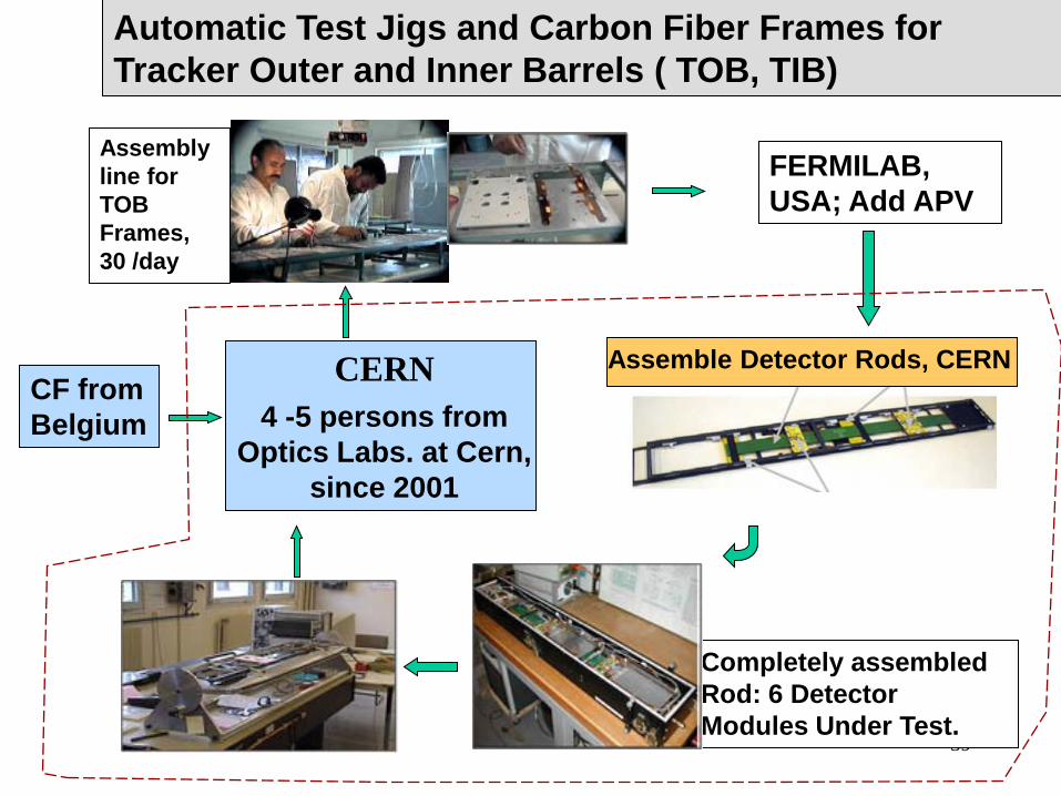
Automatic Test Jigs and Carbon Fiber Frames for Tracker Outer and Inner Barrels ( TOB, TIB)
FERMILAB, USA; Add APV
CERN4 -5 persons from
Optics Labs. at Cern, since 2001
Assembly line for TOB Frames, 30 /day
Completely assembled Rod: 6 Detector Modules Under Test.
CF from Belgium
Assemble Detector Rods, CERN

40
Collaborating Partners• S. H. Khan, B. Suleman, S.M.J. Akhtar, A. Parvez,
M. Ashraf, Farooq Ahmad, Liaquat Ali, Imtiaz Ahmad, Irshad Ahmad, Abid Ali -- (Opt. Labs - PK)
• R. Ribeiro, R. Alemany, H. Voss, K. Hopfner,S. Silva (Pedro Reis), C. Martinez, --- (CERN)
• B. Wittmer, A. Ostaptchouk, S. Schael --- (Aachen,- Ger)
• M. Vaz, J. D. Rodrigues, J. S. Gomes, T. Marques, A. Nicolau -- (FEUP & INEGI - PT)
• P. Rato, H. Gomes, P. Stallinga, M. Abreu -- (Univ. Faro & LIP PT)
40

41
o Theorise o Observe o Measure
Man’s Greatest Enterprise:
Will Talk About: Precision of Measurement Distances, Positions and Time
plus some digressions
Always worried about AbsolutesWants answers to WHY, WHERE and WHEN
All the good things in life have to do with finding answers.. ….. some bad things also
… . and think again
41

42
What is the scale of the Solar System? Universe?
What is the value of the Astronomical Unit, AU
We know that the Sun-Earth Distance ~ 150 million Km > 1 AU ; Immense figure in everyday scales
The Classical Issue: Our Place in the Universe
The Solar Parallax
and Pythagorus
42

43
Angle between thecentres of the Moon andthe Sun when the Moon'sshadow is at the half waypoint: < 87° >.
Sun ~ 20 times furtheraway than the Moon
RELATIVE DISTANCES FOR THE MOON AND THE SUN
Aristarchus of Samos (c.310 - 230 BC)
More Measurements ::: Angle ; Sun more Distant, and Larger
Accepted to Brahe (1546 - 1601)
Kepler (1571- 1630) : < 1‘, observing Mars, instead of moon
Ratio ES / EM … ~ 229 (based on an angle of 89.75° ).
Modern Value ~ 390 (angle of 89.853o)
Precision Increase: 2.75o in 2000 y, 0.103o in next 300 y !43

44
Apart from Theory, needed two more items;• Instrument: Galileo Telescope (1610) , Chronometer• Observors: • Method: Transit of Planets across the Sun
The Abs. Value of the A.U. ::: Planetary Transits
44
Edmund Halley, 1656 – 1742 to carefully observe the transit of Venus in 1761 and 1769
International ‘frenzy’ : 1761 and 1769 to observe the transits
>> Mason & Dixon ( U.S.A.), Wales ( Canada), Chappe ( Siberia) Pingre ( Madagascar), de Gentil (India)
Capt. Cook, 1769

45
Correct Measurements of the Solar Parallax
Kepler's laws : the relative distances of the planets from the Sun (in AU)
1769: absolute dimensions of the Solar System ( avg. of some dozens of observations !
Needed: A transit of Venus + two observers at different latitudes on Earth + telescopes + accurate timekeeping
45
Solar parallax : between 8.55" and 8.88".
Modern accepted value = 8.794148”CERN June 8, 2004

46
Astrolabe, Brass, 1634/5, Made by Qa’im Muhammad, Lahore, (Lewis Evans Collection, USA)
Depicts 50 stars + a gazetteer of longitudes &latitudes of 120 locations
Scales of Sines, Cosines & Cotangent (latter for determining prayer times … a scale for finding the direction to Mecca (the qibla)
The back includes a table of the planets, ...... and unusual solar calendar
Lahore School Of Astrolabe Makers Was Famous in the 16/17th Centuries
Moving About: Knowing Where You Are
46
47
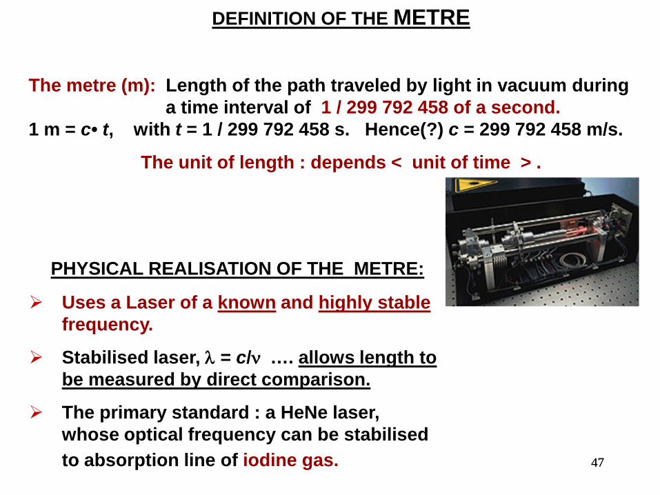
DEFINITION OF THE METRE
The metre (m): Length of the path traveled by light in vacuum during a time interval of 1 / 299 792 458 of a second.
1 m = c• t, with t = 1 / 299 792 458 s. Hence(?) c = 299 792 458 m/s.
The unit of length : depends < unit of time > .
PHYSICAL REALISATION OF THE METRE:
Uses a Laser of a known and highly stablefrequency.
Stabilised laser, λ = c/ν …. allows length to be measured by direct comparison.
The primary standard : a HeNe laser, whose optical frequency can be stabilised to absorption line of iodine gas. 47

48
Day One complete rotation time of the earth> is not a good measure of the unit of time.
a. "mean solar day" lengthened over the centuries; b. periodical (seasonal) and non-periodical variations.
Time Keeping
48
World’s timekeeping system no longer has an astronomical basis
1967 -- The 13th General Conference on Weights and Measures defined the second on the basis of vibrations of the cesium atom;
The second : duration of 9 192 631 770 periods of the radiation corresponding to the transition between the two hyperfine levels of the ground state of the caesium-133 atom.

49
NIST- F1 Cesium Fountain Atomic Clock
Primary Time and Frequency Standard:
Developed at the NIST Labs (Boulder, Colorado).
Part of the international group of atomic clocks that define Coordinated Universal Time (UTC), the official world time.
Because NIST-F1 is among the most accurate clocks in the world, it makes UTC more accurate than ever before.
How Does it Work ?? 49

50
Laser Cooled Clocks
IMPROVEMENT IN CLOCK UNCERTAINTY
NIST-F1:; 1.7 in 1015, 1 sec in 20 X106 Years; (3 X better than NIST 7 )
NIST- F2 ~ 10 x more precise than NIST-F1
NIST-F2
50

51
Atom Irradiated by a resonant photon (exact frequency)
Atom absorbs this photon; its momentum changed.
Atom is excited (typically few ns), then returns to the ground state, emitting a photon. Step repeated
Absorbed photons come from the same direction
Emission can take place in any direction in space with equal probability. On average, therefore, the momentum change over a number of emission events is equal to zero
v1, λ1 v2, λ2 …… λ = λ1+ λ2 + λ3 + λ4 ……Laser
Atomic beam
51
Laser Cooling (Nobel Prize for Physics in 1997).

52
Momentum change over a number of absorption events is not zero >> there is a net momentum transfer from light to the atom
For each absorption/emission cycle the speed of the Cs atom reduces by around 3.5 mm/s.
Apply to all three dimensions,
At the point of intersection of a number of laser beams, possible,, to cool a cloud of cesium atoms to a few µK.
v1, λ1 v2, λ2 …… λ = λ1+ λ2 + λ3 + λ4
LaserAtomic beam
52

53
Fountain Clock: Uses a fountain-like movement of atoms to measure frequency and time interval.
Cesium atoms introduced into the clock's vacuum chamber.
Six IR laser beams directed at right angles to each other >>slow down the atoms, bunch them, and cool them to temperatures near absolute zero ( ~ µ K degrees )
Two vertical lasers gently toss the ‘ball’ upward (the "fountain" action), and then all of the lasers are turned off. This little push is just enough to lIft the ball about a meter high through a microwave-filled cavity. Under the influence of gravity, the ball then falls back down through the microwave cavity. 53

5454
Video Animation of Cs Fountain Atomic Clock
http://www.colorado.edu/physics/2000/bec/images/evap2.gif
NIST Web site

55
NEW CONCEPT : FEMTOSECOND LASERS
Modelocked Femtosecond Laser:
Large gain – bandwidth product :::: used to create a set of equidistant laser frequencies.
The mode separation is given by the free spectral range of the cavity or more precisely by the pulse repetition rate.
Optical frequency comb can be used like a ruler to measure large optical frequency differences. The Modes are Distributed in frequency space within 3 parts in 1017
Mode spacing equals the pulse repetition rate within 6 x10-16
Frequency comb
55

56
A photonic crystal fiber creates additional modes via four wave mixing.The resulting frequency comb is wide enough to measure the frequency difference between a laser at f = 282 THz ( 1064 nm ) and its own second harmonic 2f ( 532 nm ).
We get the laser frequency itself: 2f - f = f.
Knowing f : know frequencies of all the modes in the comb
HENCE can be used for optical frequency measurements.
56