2011 volkswagen touareg - vw · pdf filethe 2011 touareg comes with bi-xenon headlamps that...
TRANSCRIPT

1
Volkswagen-Certified Collision Repair Facility Training
The 2011 Touareg

Volkswagen of America, Inc. ©2011 Volkswagen of America, Inc. All rights reserved. All information contained in this manual is based on the latest information available at the time of printing and is subject to the copyright and other intellectual property rights of Volkswagen of America, Inc., its affiliated companies and its licensors. All rights are reserved to make changes at any time without notice. No part of this document may be reproduced, stored in a retrieval system, or transmitted in any form or by any means, electronic, mechanical, photocopying, recording or otherwise, nor may these materials be modified or reposted to other sites without the prior expressed written permission of the publisher. All requests for permission to copy and redistribute information should be referred to Volkswagen of America, Inc. Always check Technical Bulletins and the latest electronic repair information for information that may supersede any information included in this booklet. Trademarks: All brand names and product names used in this manual are trade names, service marks, trademarks, or registered trademarks; and are the property of their respective owner. Warnings & Cautions: Volkswagen of America, Inc. provides the following repair information as a benefit to VW-Certified Collision Repair Facilities. This information is meant to supplement but not replace the repair information available from Volkswagen ElsaWeb and Erwin. VW-Certified Collision Repair Facilities should refer to ElsaWeb and Erwin for the most up-to-date and complete repair information for this vehicle.

3
Welcome Welcome to the 2011 Volkswagen Touareg information training program. This program provides an overview of the 2011 Touareg, including new features compared to the previous model, and specific body repair information that is relevant to the collision repair of this vehicle. It is important to note that while portions of the repair manual are referenced, this is not a reference source that should be used to conduct the collision repairs. All specific recommendations, such as step-by-step procedures, specific structural measurements, and sectioning locations are to be obtained from the online electronic service information such as ElsaWeb or Erwin. Topics that will be discussed in this program include: • An overview of the 2011 Volkswagen Touareg • New technologies for the Touareg • Outer body structure design • An overview of the Touareg Hybrid and related safety considerations • Restraint systems • Inspection and replacement items following restraint system deployment • The panoramic sliding sunroof • Body structure composition • Factory joining processes • Corrosion protection and foam identification • Tool recommendations • Measuring and straightening recommendations • Structural part replacement – complete and partial
4
Table Of Contents Warnings and Cautions ...............................................................................................3 Welcome ...................................................................................................................4 2011 Volkswagen Touareg Overview ...........................................................................6 New Technology Overview ..........................................................................................9 Outer Body Structure Design ...................................................................................... 11 Panoramic Sliding Sunroof ....................................................................................... 16 Interior Trim ............................................................................................................. 16 Hybrid Overview ....................................................................................................... 17 Restraint System Overview ......................................................................................... 20 Body Structure Composition ....................................................................................... 23 Factory Joining and Soundproofing Processes .............................................................. 25 Tool Recommendations ............................................................................................. 28 Measuring and Straightening Recommendations .......................................................... 30 Structural Part Replacement ....................................................................................... 31 Sectioning Recommendations .................................................................................... 37
5
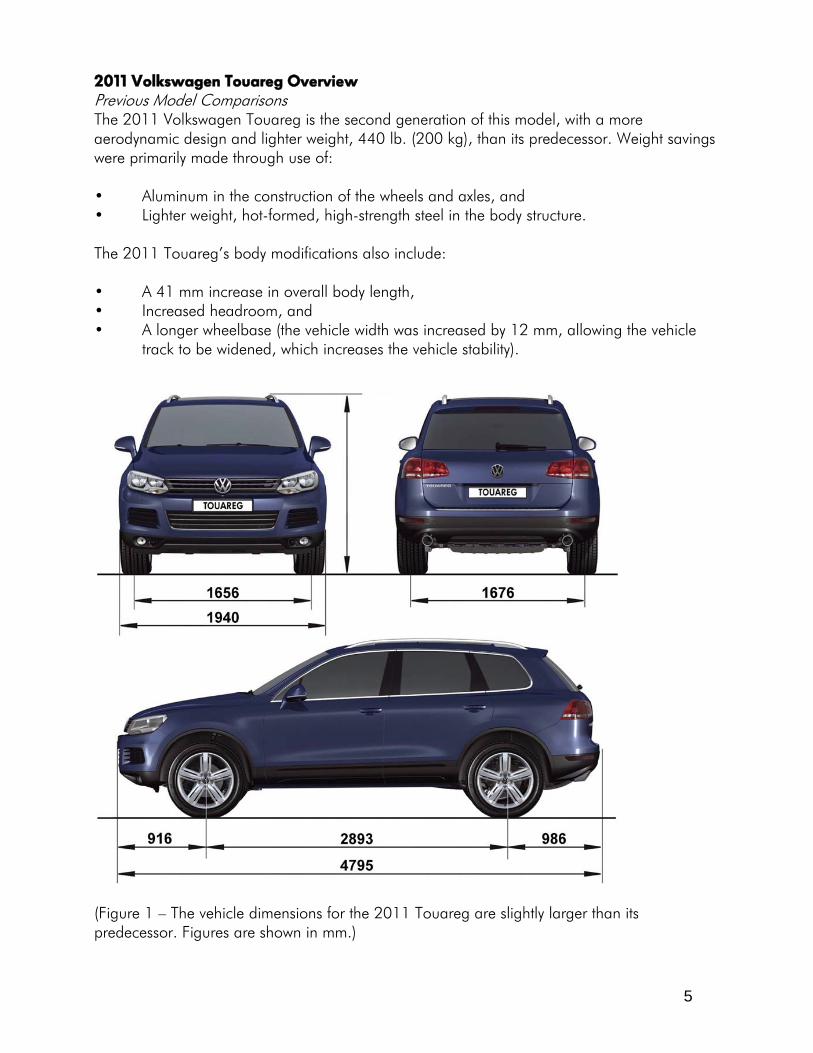
2011 Volkswagen Touareg Overview Previous Model Comparisons The 2011 Volkswagen Touareg is the second generation of this model, with a more aerodynamic design and lighter weight, 440 lb. (200 kg), than its predecessor. Weight savings were primarily made through use of: • Aluminum in the construction of the wheels and axles, and • Lighter weight, hot-formed, high-strength steel in the body structure. The 2011 Touareg’s body modifications also include: • A 41 mm increase in overall body length, • Increased headroom, and • A longer wheelbase (the vehicle width was increased by 12 mm, allowing the vehicle
track to be widened, which increases the vehicle stability).
(Figure 1 – The vehicle dimensions for the 2011 Touareg are slightly larger than its predecessor. Figures are shown in mm.)

6
VW Touareg Option Packages There are three engine options that are available for the 2011 Touareg. The first is a gasoline powered, 3.6 L, 16-valve, DOHC turbocharged engine with intercooler. This engine has 280 horsepower and provides 265 foot pounds of torque.
(Figure 2 – The 2011 Touareg is equipped with a 3.6L, DOHC engine.) There is also a diesel option. This 6-cylinder engine, the 3.0 TDI®, has a 24-valve, DOHC with common rail injection system. It produces 225 horsepower and provides 406 foot pounds of torque. The final engine option is a hybrid propulsion system. This configuration is called a parallel hybrid, with one electric motor mounted between a 6-cylinder, supercharged engine. The engine, a 3.0 L, 245 kW V6 TSI engine, has 333 horsepower and provides 325 foot pounds of torque.

7
With the new engine designs, it is important to note that the Touareg no longer is equipped with a dipstick for determining oil levels. Instead, a “realistic oil gauge” is used to provide any oil level warnings. This oil gauge is provided on the center console display. The display indicates when the oil is: • Dangerously low (B) • Low enough where more could be added (C) • Overfilled (D) • Adequate (A)
(Figure 3 – The 2011 Touareg no longer contains a dipstick, but uses a digital display to provide engine oil levels.)

8
New Technology Overview The 2011 Touareg has been equipped with new technology packages, much of which is standard. Bi-Xenon Headlamps The 2011 Touareg comes with bi-xenon headlamps that use a high-quality exterior lens with no tooled edges. This requires a special construction process where the lens is injection molded. It is the first time this type of technology is being used by Volkswagen. Additionally, for the first time, xenon headlamps are equipped with a mercury-free gas discharge light. This is in part to meet with the new European regulation requiring vehicle construction to be free of mercury and other poisonous metals. When removing or replacing the headlamp assembly, note that the front bumper cover must be removed.
(Figure 4 – The 2011 Touareg is equipped with Bi-Xenon headlamps.) Adaptive Front Lighting System (AFS) The dynamic light assist is designed to swivel the bi-xenon headlamp up to 15 degrees in the direction the vehicle is turning. The purpose of this feature is to assist the driver by directing the light around corners to increase visibility. If service must be performed on the AFS, such as lamp replacement, power to the headlamp must be switched off and the headlamp removed. Tire Pressure Monitoring System The tire pressure monitoring system is standard and has a transmitter in all four wheelhousings and a sensor on all four wheels.
9
Additional Technologies Additional technology features that have been added to the 2011 Volkswagen Touareg include: • Rearview camera • Rollover sensor system • Immobilizer theft-deterrent system • Intelligent crash response system (ICRS) • Anti-slip regulation (ASR) • Electronic brake-pressure distribution (EBD) • Hill descent assist • Electronic stabilization program (ESP) • Blinker control stalk with lane change feature

10
Outer Body Structure Design Fenders The fenders on the 2011 Touareg are made from steel that is .65 mm thick. This is a departure from the previous model where the fenders were made from plastic. It is important to note that during fender removal, the upper fender bolt may be hidden by windshield adhesive. If this is the case, the windshield must be removed to remove the fender. The fenders are secured on the sides with retaining plates, specifically used for pedestrian protection. On diesel vehicles, the auxiliary heater must first be removed before the fender can be removed. Also, parts of the tire pressure monitoring system are on the fender, so do not cut any wires to remove the fender. The fender on the right side has the windshield washer fluid reservoir fitted beneath it.
(Figure 5 – The fender removal process may require removal of the windshield if the upper bolt cannot be accessed.)

11
Bumpers The front bumper covers are made from PP/EPDM and may be repaired if damaged using plastic repair techniques outlined in the service information. Height adjusters are used to position the bumper cover during installation and the bumper cover is essentially set on the height adjusters before the bumper is secured.
(Figure 6 – The bumper height adjuster is used to position the bumper during installation.) A new feature for pedestrian safety is the addition of an impact crossmember tube. This tube is mounted to the bumper reinforcement with two bolts. This tube has been added in addition to the existing pedestrian safety foam that is also mounted to the bumper reinforcement.
(Figure 7 – The impact crossmember tube is used for pedestrian safety.)

12
Rear Bumper To remove the rear bumper cover, it is necessary to remove the tail lamps first. There are two upper screws behind the tail lamps that must be removed to remove the bumper cover. Additional screws are located on the underside and adjacent to the wheel arch cover.
(Figure 8 – Rear bumper cover removal requires the taillamps be removed first.)

13
When a new rear bumper cover is ordered, it is shipped without the holes for installing the parking assist sensors. Therefore, holes must be drilled by the repair facility. Volkswagen provides a kit (VAS 6614/1/2/3) and procedure that is designed to create smooth hole cutouts for the parking sensors. The kit contains a die that is the diameter of the parking assist sensor. This die is used with a socket wrench. As the head of the die is tightened with the wrench, the die cuts through the bumper cover creating the proper sized hole for the sensor. Specific hole locations are shipped with markings in the bumpers.
(Figure 9 – Volkswagen provides a die kit, part numbers VAS 6614/1, 6614/2, 6614/3, for creating rear bumper sensor holes.) Doors The exterior trim near the door moveable glass is friction fit onto the door assembly. The chrome part has a tight fit, and if the chrome is bent, it must be replaced. The rear door trim uses clips, while the front door trim is attached using screws. Rear doors may be equipped with antennas for keyless entry. The other keyless entry antenna is positioned under the dash. Door Glass Removal And Installation Removing the door glass on the rear door requires: • Removing the door trim, • Removing the cap, • Lowering the door glass until the bolt that attaches the glass to the regulator is
accessible through a bolt hole, • Loosening the bolt that connects the window regulator to the glass, • Loosening the clamping bracket, • Removing the door trim adjacent to the window frame, and • Removing the glass upward and at an angle.

14
To install the door glass, reverse the procedure and perform a function test after the door trim is installed. Make sure all bolts are torqued as recommended in the service information. Tailgate The tailgate is single piece steel construction. Considerations for working on parts of the tailgate include making sure to remove the interior trim from the tailgate when replacing the high-mount tail lamp. There are clips on the backside of the lamp assembly that must be disengaged before removing the lamp from the tailgate. The tailgate also has sensor strips attached to each side that provide an audible alarm to indicate if anything is being pinched between the tailgate and the vehicle, and stops the closing motion.
(Figure 10 – The sensor strips on the tailgate opening prevent pinching.)

15
Fuel Filler Door Module When removing the fuel filler door, it is destructive to the door. When removing the fuel filler door module, it is necessary to punch through at all four points so the latches underneath can be released.
(Figure 11 – The fuel filler door must be replaced if removed.) Panoramic Sliding Sunroof The panoramic sliding roof, made from 5 mm thick safety glass, has the same structural design as the VW Tiguan. On the sliding roof, the forward glass slides back, or tilts, and the rear glass panel does not open. The sliding sunroof module is equipped with a roller blind that is operated from front to back. When the sunroof is opened, the roller blind will retract. Drain hoses for the sliding sunroof are routed to the A- and B-pillars. Interior Trim There have been some minor modifications to the trim attachment methods. The trim for the 2011 Touareg no longer uses bolts for attachment, rather the trim is attached with clips to the vehicle structure. Additionally, the B-pillar vents have been discontinued, so these are no longer seen on the trim.
16
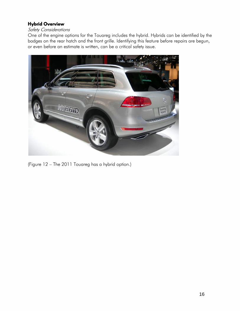
Hybrid Overview Safety Considerations One of the engine options for the Touareg includes the hybrid. Hybrids can be identified by the badges on the rear hatch and the front grille. Identifying this feature before repairs are begun, or even before an estimate is written, can be a critical safety issue.
(Figure 12 – The 2011 Touareg has a hybrid option.)

17
The Touareg hybrid system is capable of producing 288 volts of electricity, which is enough to cause serious injury or death to a technician who is unfamiliar with the high-voltage cables in the vehicle.
(Figure 13 – This shows the high voltage wiring route on the vehicle underbody.) To identify high voltage cables, they are color-coded orange, making them easily identifiable when the hood or battery storage area is opened. Parts connected to the high voltage system include: • Power electronics that convert high voltage into low voltage • The high voltage battery • The electric motor • The A/C compressor • The electric box that contains the control unit for controlling the high voltage battery
and the maintenance connector

18
Common safety considerations include: • Never touch energized high voltage cables or parts or use them to support tools. • Do not work near high voltage parts with sharp-edged tools or sources of heat, such as
welders. • Do not severely bend or kink high voltage lines. Volkswagen recommends that a technician who is trained on hybrid systems be responsible for disabling the high voltage system. This person will also be responsible for attaching signage stating that the vehicle has been de-energized.
(Figure 14 - This shows the battery disconnect, high-voltage wiring, and battery located in the rear of the vehicle.)

19
Restraint System Overview Airbags The passenger cabin is equipped with a maximum of six airbags. These include: • Seat-mounted side airbags for the driver and passenger • Side curtain airbags, front and rear • Driver and passenger airbags (the driver airbag module is a single-stage design, while
the passenger airbag module is two stage; to remove the passenger airbag module, note that the glovebox must first be removed).
(Figure 15 – Curtain airbags and side impact airbags are standard.)

20
The Touareg is equipped with four impact sensors. There are two located in the front end of the vehicle, and one on each side. The side sensors are pressure sensors located in the front doors. Using pressure sensors in the doors can have up to 30% faster response time than conventional acceleration-based, side-impact sensors. The sensors do not rely on an airtight seal in the door cavity, as there are air openings in several places in a door shell. The sensors respond to a quick collapsing of the door shell, indicating a side collision.
(Figure 16 – Door mounted pressure sensors are used for side impact deployment.)
(Figure 17 – The 2011 Touareg is equipped with six airbags.)

21
Seat Belt Pre-Tensioners Pre-tensioners are equipped on the driver and passenger seat belts that are designed to remove slack in the belt prior to a collision. A new seat belt pre-tensioner, similar to Audi TT, is spring activated. There is also a pyrotechnic pre-tensioner that is used with airbag deployment.
(Figure 18 – The seat belt pre-tensioner is standard and deploys with the airbags.) Inspection/Replacement Items Following Restraint System Deployment After airbag deployment, the following parts MUST be replaced: • All deployed airbag modules • Supports and the bracket of the front passenger airbag unit in the case of a deployed
front passenger airbag • Return ring with slip ring, in the case of a deployed driver airbag • All seat belts with deployed seat belt tensioners Visually inspect all airbag system related parts and replace any faulty parts. If there is a collision without an airbag deployment, verify that the airbag lamp is not lit and check seat belts for any defects.

22
Body Structure Composition The body of the 2011 Volkswagen has been completely redesigned to increase body stiffness and decrease vehicle weight. To accomplish this, ultra-high-strength, hot-formed steel is used in the construction of the following parts: • Upper A-pillar • Parts of the roof side member • Inner B-pillar • Bench seat crossmember • Roof crossmember (in vehicles without panoramic sliding roof) Strength of these parts is 1,350–1,600 MPa.
(Figure 19 – UHSS is used in the side structure and vehicle crossmembers.)
23
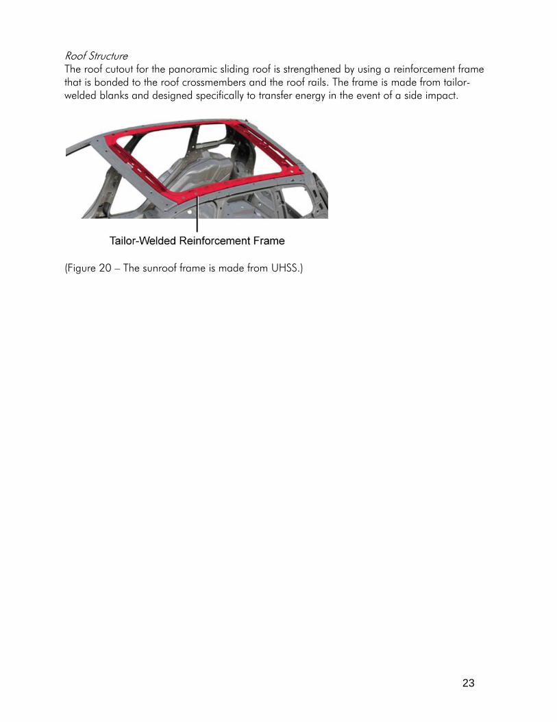
Roof Structure The roof cutout for the panoramic sliding roof is strengthened by using a reinforcement frame that is bonded to the roof crossmembers and the roof rails. The frame is made from tailor-welded blanks and designed specifically to transfer energy in the event of a side impact.
(Figure 20 – The sunroof frame is made from UHSS.)

24
Factory Joining and Soundproofing Processes The factory joining processes include the use of: • laser welds • Spot welds • Adhesives • GMA (MIG) welds • Brazing Laser Welds The roof and some body parts are attached using laser welds. With laser welds, the upper plate is melted through and the lower plate is partially melted, forming a weld without any filler materials. This process cannot be duplicated in the collision repair facility. Therefore, Volkswagen recommends replacing laser welds with spot welds. Foam Identification Areas of factory foam installation include the bottom of the B-pillar, bottom of the A-pillar, mid-way up the A-pillar near the bottom of the windshield opening, the dogleg area, C-pillar and sail panel in the quarter glass area. Soundproofing The points at which foams are fitted to the vehicle during production are marked on the part. In case of repair, a mold from a metal plate, which can be ordered as a spare part, must be prepared in accordance with the repair guideline from ElsaWeb. This substitute soundproofing material will be installed with butyl sealing compound before welding. There is soundproofing foam on the fenders. It is wedged between the upper rail and the fender. Additional soundproofing foam can be found at the C-pillar that fits between the wheelhouse and outer section. During repair, the foam is reinstalled using the procedures outlined in ElsaWeb.

25
Corrosion Protection The areas marked yellow are preserved with wax as an anti-corrosion measure. These areas must be restored following any collision repair work. Use the recommended product and application equipment as outlined in ElsaWeb.
(Figure 21 – This shows anti-corrosion compound application locations.)

26
The points at which underbody protection is applied during production are marked. The color key specifies the different material thicknesses. In case of repair, rework must be carried out according to the specifications in the repair guideline from ElsaWeb.
(Figure 22 – Here are the undercoating location categorized by material thickness.)

27
Tool Recommendations Spot Welders Volkswagen has five spot welders that are part of their recommended tool list. The Volkswagen part numbers for these include: • VAS 6530: Techna Inverter Welder • VAS 6535: Elektron Inverter Welder • VAS 6545: Weidlander + Schill Inverter Welder
(Figure 23 – This is one of the Volkswagen recommended spot welders.) The spot welders are equipped with computer programs designed to provide the proper power to the welding tips to weld varying types of high strength and ultra-high-strength steels. They are also equipped with varying arm configurations to aid in the spot welding process on hard-to-reach areas.

28
Caution: • Before welding (either spot welding or GMA (MIG)), the battery must be completely
disconnected on both battery posts. Additionally, the battery should be removed if welding operations are near the battery.
• Before disconnection, make sure the radio code is available. • Connect the ground connection of the welder directly to the part being welded. Make
sure that no electrically insulated parts are between the ground connection and the welding point.
• Follow all safety recommendations outlined in the electronic service information. Laser Weld Removal Volkswagen has a laser weld bit and tool (VAS6913) that can be set to the proper depth to make sure laser welds have been removed without cutting into the panel beneath. Gap Gauges Gap gauges (part # 3371) are available from Volkswagen and are used to determine proper windshield, hood, fender, hatch, and A-pillar gaps, to name a few. There are slight gap tolerances that are provided in the ElsaWeb service information.
(Figure 24 – These gap gauges are provided by Volkswagen.)
29
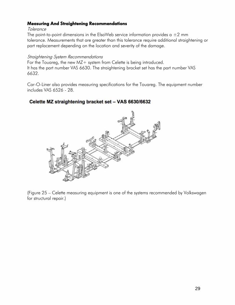
Measuring And Straightening Recommendations Tolerance The point-to-point dimensions in the ElsaWeb service information provides a ±2 mm tolerance. Measurements that are greater than this tolerance require additional straightening or part replacement depending on the location and severity of the damage. Straightening System Recommendations For the Touareg, the new MZ+ system from Celette is being introduced. It has the part number VAS 6630. The straightening bracket set has the part number VAS 6632. Car-O-Liner also provides measuring specifications for the Touareg. The equipment number includes VAS 6526 - 28.
(Figure 25 – Celette measuring equipment is one of the systems recommended by Volkswagen for structural repair.)

30
Structural Part Replacement The 2011 Touareg offers multiple part sectioning options. Many of the sectioning procedures for specific parts have multiple sectioning locations that can be used. Refer to ElsaWeb for exact cutting locations. Below is a summarized list of what parts can be sectioned on the 2011 Volkswagen Touareg. Part Identification Sectioning Procedure
Available Complete Replacement Only
Upper Rail X Lower Rail X Outer A-Pillar X A-Pillar Reinforcement X Outer B-Pillar X Inner B-Pillar X Inner B-Pillar Reinforcement X Outer Rocker Panel X Inner Rocker Panel X Rear Rail X Rear Body Panel X Quarter Panel X Bumper Brackets The bumper brackets are welded to the front lower rail with GMA (MIG) welds. The replacement brackets are available separate from the front lower rail. The replacement piece is welded in place using a continuous weld seam at locations specified in ElsaWeb.

31
Lower Rail The front lower rail is a tailor-welded blank assembly that, when completely replaced, requires cutting an access window through the floor pan to reach the fillet welds beneath. The access hole dimensions include: • a = 115 mm • b = 30 mm • c = 10 mm • d = 80 mm Once access is gained, the fillet welds can be ground down to remove the front rail assembly.
(Figure 26 – To remove the front lower rail, this access hole must be made in the floor to remove the GMA (MIG) welds.) In addition to the access hole, complete replacement of the front rail requires that the upper rail section be removed and that the strut tower mount is loose at the connection point to the lower rail. Front Lower Rail Installation Plug weld holes for front lower rail installation have an 8 mm diameter. These are used to replace the removed spot welds. Distance between plug weld holes should be similar to the distance used between the spot welds on the damaged part. It may be helpful to use the damaged part as a reference. After the lower rail has been installed, the plate on the floor pan must be welded back in place. When installing the floor pan plate, the repair must be welded so that it is watertight.
32
Roof During vehicle assembly, the roof is attached to the roof rails using laser brazing. Structural adhesive is used to attach the front and rear of the roof to the front and rear crossmembers, in addition to attaching the roof to the roof bows. When removing the roof panel, Volkswagen recommends rough-cutting the roof panel, maintaining a distance of 15 mm from the roof rail. This ensures that the roof rail does not get damaged during the removal process. Also, the adhesive bonds should be loosened from inside the vehicle. Before removing the roof panel, separate the bonded joints that attach the roof panel to the roof bows. To remove the remaining parts of the roof, use a Lamellar disc to separate the remaining roof metal from the roof rail. Roof Panel Replacement The replacement roof is bonded and spot welded to the vehicle structure. Volkswagen provides specific product recommendations for the type of adhesive. The part number for the adhesive is D 180 KD3 A2. Replacing the roof panel requires: • Sanding all the edges of the roof panel that will match up with the roof rail. The area
should be sanded to bare metal (this is recommended to ensure proper adhesion of the adhesive to the substrate),
• Sanding the areas on the water drain to bare metal (this is done for the MIG brazing process to ensure proper adhesion),
• Positioning the suction cups on the outer side of the roof panel to lift the panel into place (the suction cups can be purchased and have a part number of V.A.G. 1344.
• Test-fitting the roof on the vehicle, making sure that the roof fits correctly and checking gaps with the windshield and adjacent panels),
• Measuring to specific points on the roof, mark these points, and install tensioning straps at each of these points (these straps are used to prevent the roof from lifting or sliding after the roof has been installed), and
• Making sure there is the proper roof alignment to the roof rails (all dimensions can be found in the roof replacement section in the ElsaWeb).
Once the roof has been test fit, the replacement roof can be prepped and installed. Procedures for prepping and installing the roof include: • Applying corrosion protection to bare metal areas outside the bonding area, • Cleaning the bonding areas with wax and grease remover, • Preparing the adhesive cartridges and tips (VW has a specific part number for the
adhesive dispensing gun – V.A.G. 1761/1. Use the bead height and width dimension outlined in ElsaWeb),
• Applying 1K assembly adhesive around the roof pillars (product number D190 MKD A3—1),
• Applying 1K assembly adhesive to the inner side of the roof, parallel to the left and right roof flange,

33
• Applying 2K body adhesive to the area that was MIG brazed at the factory (product number D 180 KD3 A2; This bead is directly adjacent to the 1K bead of adhesive that is already applied),
• Applying 2K body adhesive on the rear roof crossmember near the adhesive applied at the factory, and
• Applying 2K body adhesive to the roof flanges that go along the roof rails.
(Figure 27 – The 2K adhesive is applied adjacent to the 1K adhesive bead.)
(Figure 28 – Adhesive is applied to the roof panel flange.)
34
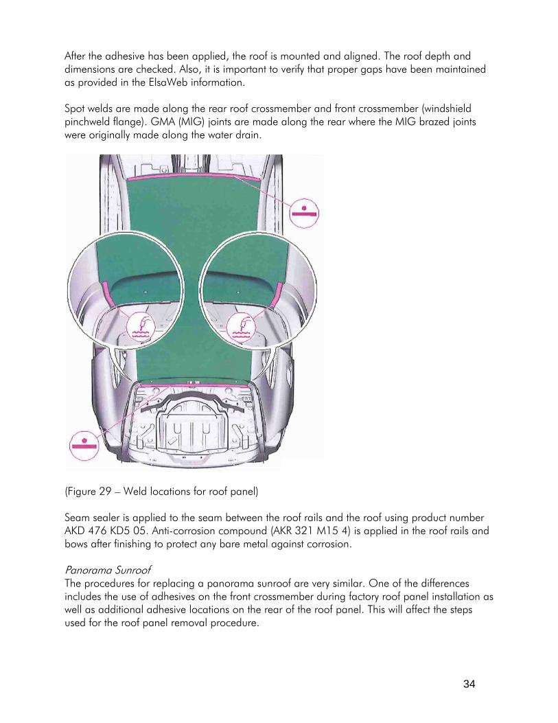
After the adhesive has been applied, the roof is mounted and aligned. The roof depth and dimensions are checked. Also, it is important to verify that proper gaps have been maintained as provided in the ElsaWeb information. Spot welds are made along the rear roof crossmember and front crossmember (windshield pinchweld flange). GMA (MIG) joints are made along the rear where the MIG brazed joints were originally made along the water drain.
(Figure 29 – Weld locations for roof panel) Seam sealer is applied to the seam between the roof rails and the roof using product number AKD 476 KD5 05. Anti-corrosion compound (AKR 321 M15 4) is applied in the roof rails and bows after finishing to protect any bare metal against corrosion. Panorama Sunroof The procedures for replacing a panorama sunroof are very similar. One of the differences includes the use of adhesives on the front crossmember during factory roof panel installation as well as additional adhesive locations on the rear of the roof panel. This will affect the steps used for the roof panel removal procedure.

35
Inner B-Pillar Replacement The inner B-pillar has an additional reinforcement installed behind the outer reinforcement. There are no sectioning procedures for the inner B-pillar or the additional reinforcement. If there is damage requiring replacement, both the inner B-pillar and the reinforcement must be completely replaced. Note that the B-pillar reinforcement is attached to the structure using laser welds along the seams. When ordered, the replacement part comes with four different parts – a backing plate, inner reinforcement, outer reinforcement, and outer skin.
(Figure 30 – The inner B-pillar reinforcement is made from UHSS and cannot be sectioned.)
(Figure 31 – The laser welds are used to attach the inner B-pillar to the vehicle structure.)

36
Sectioning Recommendations Upper Rails The upper rail offers a sectioning location. The sectioning joint is offset by 170 mm. The rear cut location is located beneath the hood buffer mount, requiring one side of the buffer to be removed before cutting. The hood buffer is riveted at the factory but reinstalled using GMA (MIG) plug welds. Replacement parts are welded in place using GMA (MIG) fillet welds. Lower Rails (Short And Long Section Joints) The front lower rail can be sectioned in two areas. The first joint is behind the strut tower, about 40 mm ahead of the firewall. The second measuring point on the outside of the front rail is about 90 mm from a circular dimensional reference point.
(Figure 32 – For front lower rail removal, the highlighted welds must be removed.)
(Figure 33 – This is the sectioning location for the outer portion of the front lower rail.)
37
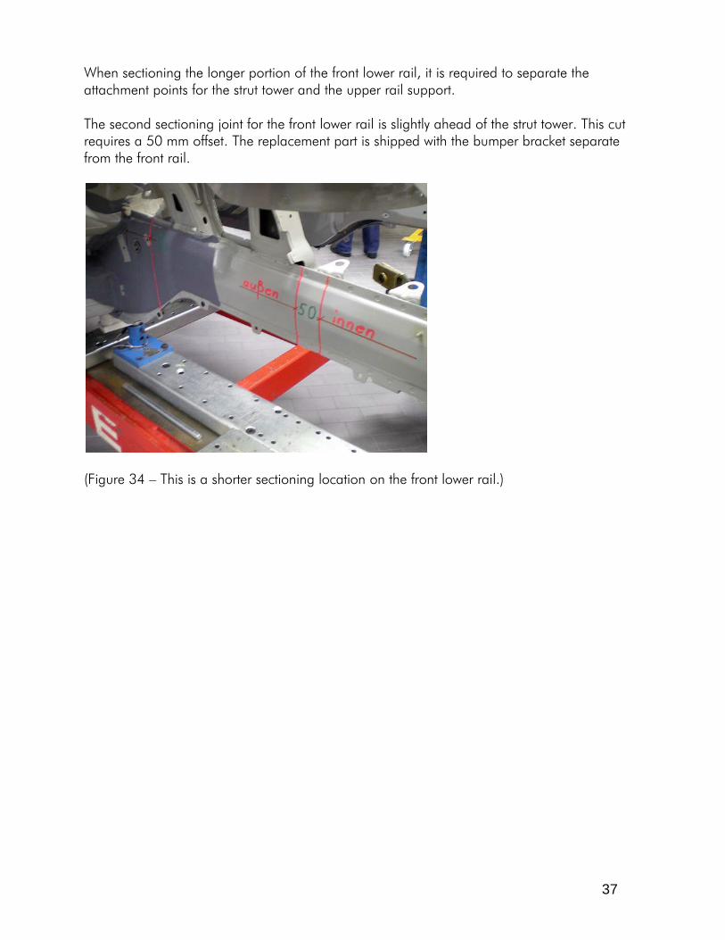
When sectioning the longer portion of the front lower rail, it is required to separate the attachment points for the strut tower and the upper rail support. The second sectioning joint for the front lower rail is slightly ahead of the strut tower. This cut requires a 50 mm offset. The replacement part is shipped with the bumper bracket separate from the front rail.
(Figure 34 – This is a shorter sectioning location on the front lower rail.)

38
A-Pillar The A-pillar can be sectioned with the cut location about 150 mm from the top of the windshield pinchweld flange and 475 mm from the leading edge of the rocker panel.
(Figure 35 – The A-pillar provides multiple sectioning locations.)
39
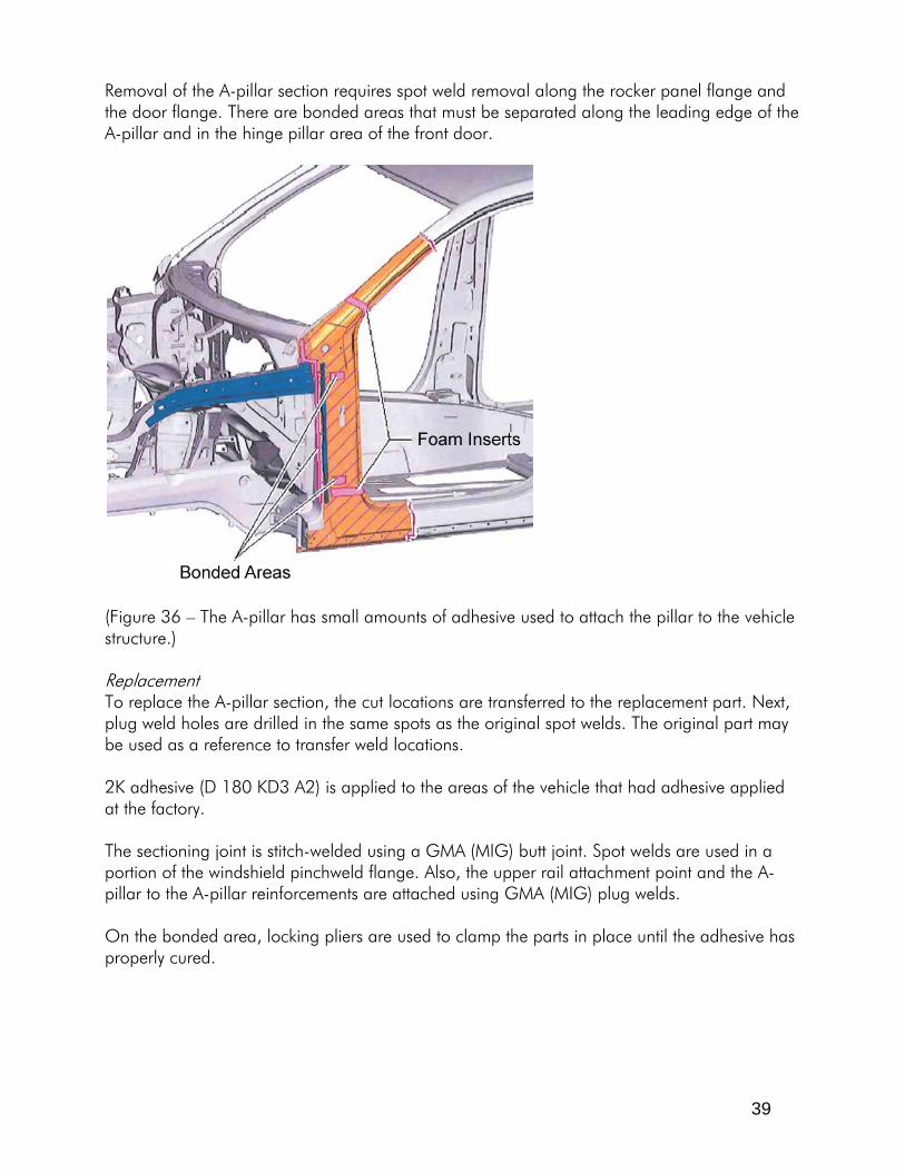
Removal of the A-pillar section requires spot weld removal along the rocker panel flange and the door flange. There are bonded areas that must be separated along the leading edge of the A-pillar and in the hinge pillar area of the front door.
(Figure 36 – The A-pillar has small amounts of adhesive used to attach the pillar to the vehicle structure.) Replacement To replace the A-pillar section, the cut locations are transferred to the replacement part. Next, plug weld holes are drilled in the same spots as the original spot welds. The original part may be used as a reference to transfer weld locations. 2K adhesive (D 180 KD3 A2) is applied to the areas of the vehicle that had adhesive applied at the factory. The sectioning joint is stitch-welded using a GMA (MIG) butt joint. Spot welds are used in a portion of the windshield pinchweld flange. Also, the upper rail attachment point and the A-pillar to the A-pillar reinforcements are attached using GMA (MIG) plug welds. On the bonded area, locking pliers are used to clamp the parts in place until the adhesive has properly cured.

40
Inner A-pillar To remove the inner A-pillar, the connection point to the upper front rail must first be separated from the hinge pillar. Next, the inner A-pillar is separated by drilling out the welds from the inside of the vehicle.
(Figure 37 – This highlights the weld locations that must be removed to separate the inner A-pillar from the vehicle structure.) A-Pillar Reinforcement Installation Installation of the replacement A-pillar reinforcement includes: • Drilling 8 mm plug weld holes in the flanges of the replacement reinforcement, • Test-fitting the new reinforcement to make sure it aligns with adjacent parts, • Applying adhesive to the flanges of the vehicle, in the same location as the original
adhesive, • Attaching the replacement reinforcement, and • Welding in place.

41
B-Pillars – Outer Spot welds are used on the outer B-pillar flanges for attachment to the inner structure. Adhesive is also used to attach the outer pillar to the inner structure. There are two sectioning locations on the outer B-pillar and three cut locations on the outer rocker panel.
(Figure 38 – The sectioning locations for the outer B-pillar are shown here.) Outer B-Pillar Removal Sectioning the outer B-pillar requires: • Making the desired cuts based on the damage and the recommended sectioning
locations provided on ElsaWeb, • Separating the panel flanges by drilling out the spot welds, • Separating the bonded areas, and • Removing any residual material from the remaining flanges. Outer B-Pillar Installation Installing the replacement outer B-pillar includes: • Transferring the cut locations to the replacement outer B-pillar, • Applying two layers of sealing cord (product #AKD 497 010 04 R10) in the area of the
molded foam piece, • Test-fitting the replacement part, • Applying the adhesive to the same areas that were bonded during factory assembly, • Applying the adhesive to the panel flanges (Use the two-part adhesive, product #D 180
KD3 A2. Only one 4 mm bead should be used), • Installing the replacement part, making sure to wipe any residual adhesive out of the
hinge mount holes and striker pin holes, • Using spot welds to attach the B-pillar in place, and • Using a GMA (MIG) butt joint on the sectioning joints.

42
Rocker Panel – Outer The outer rocker panel has cut locations at the A-pillar, B-pillar, and dogleg area. The specific cut lines are provided in ElsaWeb.
(Figure 39 – These are the sectioning locations for the outer rocker panel.) Rocker Panel Outer – Removal Removing the rocker panel section includes: • Making the cuts at the recommended cut locations, • Removing the spot welds, • Removing any residual adhesive, grinding the bonding surfaces down to the bare metal,
and • Applying any corrosion protection that may have been removed during the panel
removal process. Rocker Panel Outer – Installation To install the outer rocker panel section requires: • Transferring the sectioning locations to the replacement part, • Drilling 8 mm plug weld holes along the leading edge of the rocker panel (on the A-
pillar flange), • Installing the molded foam inserts, • Test-fitting the replacement panel, • Removing the panel and apply the two part adhesive along the rocker panel flange, • Using GMA (MIG) butt joints on the sectioning locations, and • Using spot welds along the panel flanges.

43
Inner Rocker Panel Section – Center Section - Removal When sectioning the inner rocker panel center section, there are multiple sectioning locations to choose based on the extent of damage. The inner rocker can be sectioned anywhere between the sectioning locations shown in the illustration below. Procedures for sectioning the inner rocker panel reinforcement include: • Removing the outer B-pillar and B-pillar reinforcement, • Choosing the sectioning joints in the front door sill based on the extent of damage
(follow specific cut locations outlined in ElsaWeb), • Removing the damaged inner rocker panel reinforcement. Laser welds will need to be
removed, • Separating the joint connecting the reinforcement to the bar pieces inside the
reinforcement, and • Removing any residual material from the remaining flanges and structure.
(Figure 40 – These are the inner rocker panel sectioning locations.)

44
Installing the replacement reinforcement includes: • Transferring the cut lines to the replacement rocker panel reinforcement and cutting to
proper fit, • Removing 200 mm of the leftover replacement part and 140 mm of the leftover
replacement part for backing plates, • Drilling 8, 8 mm plug weld holes into the replacement reinforcement, • Separating the flanges of the cut areas of the reinforcement (blue areas), • Installing the molded foam part that replaces the factory-installed foam, • Using spot welds to attach the reinforcement in place, • Using a GMA (MIG) butt joint at the sectioning location, • Welding the original joint on the reinforcement and on the inside of the sill panel with a
straight-line spot weld seam, and • Using GMA (MIG) plug welds to attach the bar pieces to the reinforcement.
(Figure 41 – These are the inner rocker panel backing plates for the sectioning joints (in blue).)

45
Rear Rail The rear rail also offers sectioning possibilities. When sectioning the rear rail, the cut must be made either 50 mm in front of or behind the laser weld seam. The laser-welded seam is NOT to be used as a cut line for sectioning.
(Figure 42 – This is the rear rail sectioning location.)

46
Conclusion Congratulations! You have completed the Volkswagen Touareg Collision Repair Information training program. Thank you for taking the time to complete this course. You should now be able to: • Provide an overview of the Volkswagen Touareg. • List the option packages that are available. • Provide an overview of the various types of body construction materials. • Provide an overview of the factory joining processes. • List spot welder recommendations. • List roof panel replacement procedures. • List various part replacement recommendations. • List sectioning recommendations for primary structural parts.