20110901 argonne national labs dibble berkeley dibble-presentation… ·...
TRANSCRIPT

Please Bring Your “Out of the Box” Ideas to the High Pressure Combus<on Workshop
High Pressure Combus<on Workshop At Argonne Na<onal Laboratories
Aug 2011
Robert W. Dibble UC Berkeley
Funded by DoE and KAUST

Buy This Book !

Out of the Box The W number
3 Benjamin Wolk – UC Berkeley
All chemical reac<ons should get a permanent number that is Decimal. As new reac<ons are discovered, they can be assigned Numbers close to other reac<ons. Thus CO + OH => CO2 + H could be W 2.3 hypothe<cal new reac<on CO + OOH => CO2 + OH could be W 2.3101 for example W for Westbrook, Warnatz, Wolfrum, Woolbridge, Wolker And Joe Micheals and Jim Miller (because “M” is “W” upside down

Out of the Box
4 Benjamin Wolk – UC Berkeley
1….Rudy Marcus visits Berkeley (Marcus is the “M” in RRKM ) He Lectures on 1…H2O(18) in ocean is different than H2O(18) in air And 2…… CO + OH = CO2 + O “strange reac<on” He was so excited about 1, that he never got to 2

Rate 2 governs at low temps; Rates 1 and 3 govern at high temperatures
Ea (kJ/mol) A0 (cc/mol-‐s) b
1 2 3 46
7
8
9
10
11
12
1000 K/T [-]
log(
k /c
m3 •
mol
-1 •
s-1
)
CO + OH = CO2 + H
Rate 1Rate 2Rate 3Sum
Rate 1 Rate 2 Rate 3

Buy This Book !
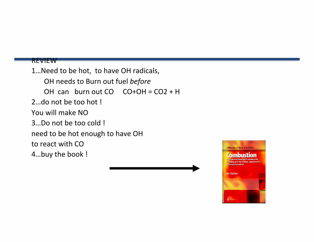
REVIEW 1…Need to be hot, to have OH radicals, OH needs to Burn out fuel before OH can burn out CO CO+OH = CO2 + H 2…do not be too hot ! You will make NO 3…Do not be too cold ! need to be hot enough to have OH to react with CO 4…buy the book !

Out of the Box
8 Benjamin Wolk – UC Berkeley
1….Downsizing is leading to turbocharging, Thus higher pressures, thus more demand on Spark electronics and electrodes. Advanced Sparking systems are being explored “1kg reduc+on of engine mass, 2kg reduc+on in vehicle mass “

Out of the Box (about 1970)
9 Benjamin Wolk – UC Berkeley
Rolls-‐Royce Diesel | Rolls-‐Royce.Edmunds.com www.rolls-‐royce.edmunds.com Rolls-‐Royce Research, Reviews & Latest Prices! Free Info. ► Search Results The Wankel Rotary Engine: A History books.google.comJohn B. Hege -‐ 2006 -‐ 174 pages -‐ Google eBook -‐ Preview The work done by several companies to overcome these problems is described in detail, as are the economic and poli<cal troubles that nearly killed the rotary in the 1970s, and the prospects for future rotary-‐powered vehicles. More edi<ons Add to My Library▼ Popular Science -‐ Feb 1971 -‐ Page 80 books.google.comVol. 198, No. 2 -‐ 162 pages -‐ Magazine -‐ Full view A Diesel Wankel from Rolls-‐Royce By DAVID SCOTT / PS European Editot LJp to now, all Wankel engines— NSU, Mazda, Cur<ss-‐Wright, Mercedes-‐Benz—have been preny much alike. They run on gasoline, are fired by spark plugs, ...
Add to My Library▼ The rotor can take much more pressure, say 400 bar “Wankel boos<ng Wankel”

HCCI is not new !
Lohmann HCCI engine, ca 1952 (> 1949) no<ce: no spark plug carbureted, 70$
ALL: find one (or earlier, bulb engines ca 1900. Also, there are web sites; old farm machines


Out of the Box
12 Benjamin Wolk – UC Berkeley
The Argon Engine at Argonne Labs Argon, mono atomic, with gamma=1.67 No vibra<onal or rota<onal degrees of freedom Conver<ng Chemical energy to vibra<onal energy Is wasteful, thus, nitrogen in engines is not op<mal

The Argon Engine Project
H2-‐O2-‐Ar Internal Combus<on Engine: the Mechanical Equivalent of a Fuel Cell
“We believe we can build the cleanest and most efficient
engine in history (~50% and zero emissions) by optimizing the working medium (argon instead of nitrogen)”
Professors Dibble and Chen Collabora<on with Dr. Aceves at LLNL
UC Berkeley
April 1, 2008

Low temperature combus;on requires high dilu;on levels -‐ A challenge at high load
Prof. Bengt Johansson Div. of Combus<on Engines, Dept. of Energy Sciences

Energy flow in an IC engine
FuelMEP
QhrMEP
IMEPgross
lMEPnet
BMEP
QemisMEP
QlossMEP
QhtMEP
QexhMEP
PMEP
FMEP
Combustion efficiency
Thermodynamic efficiency
Gas exchange efficiency
Mechanical efficiency
Net Indicated efficiency
Brake efficiency
Gross Indicated efficiency
FuelMEP
QhrMEP
IMEPgross
lMEPnet
BMEP
QemisMEP
QlossMEP
QhtMEP
QexhMEP
PMEP
FMEP
Combustion efficiency
Thermodynamic efficiency
Gas exchange efficiency
Mechanical efficiency
Net Indicated efficiency
Brake efficiency
Gross Indicated efficiency
ηηηηη MechanicaleGasExchangmicThermodynaCombustionBrake***=
15 Slide from Prof. Bengt Johansson

Today’s engines have efficiency (30-40%)
due to the thermodynamics of air-fuel mixtures (specific heat ratio cp/cv = γ <
1.4 for air, 1.67 for Argon)
00.10.20.30.40.50.60.70.80.91
1 3 5 7 9 11 13 15 17 19compression ratio, CR
idea
l eng
ine
effi
cien
cy
1
11 −−= γCRefficiencyengine
g =1.3
g =1.4
gasoline engines
diesel
g = cp/cv, specific heat ratio
CR
Effic
ienc
y

0
0.1
0.2
0.3
0.4
0.5
0.6
0.7
0.8
0.9
1
1 3 5 7 9 11 13 15 17 19
compression ratio, CR
idea
l eng
ine
effi
cien
cy
We believe we can build the cleanest and most efficient
engine in history (~60% and zero emissions)
by optimizing the working medium (argon instead of nitrogen)
1
11 −−= γCRefficiencyengine
g =1.67
g =1.3
g =1.4
gasoline engines
diesel
H2-O2-Ar engines
g = cp/cv, specific heat ratio
Effic
ienc
y
CR

H2-‐O2-‐Ar Internal Combus<on Engine System:
The Mechanical Equivalent of a Fuel Cell Salvador M. Aceves (LLNL) Robert Dibble (UC Berkeley)
Next Steps Stopped by Knock, Thus Convert to Diesel Mode Inhale Argon plus 10% hydrogen Inject liquid : H2O2 or N2O or ?

Limits of MicroWave Assisted Combus<on (mWASP) in Constant Volume Combus<on Chamber
High Pressure Combus<on Workshop At Argonne Na<onal Laboratories
Aug 2011
B. Wolk, A DeFilippo, JY Chen, R Dibble (UC Berkeley) A Nishiyama, Y Ikeda (Imagineering Inc.)
Funded by DoE and KAUST

Limits of MicroWave Assisted Combus<on (mWASP) in Constant Volume Combus<on Chamber
High Pressure Combus<on Workshop At Argonne Na<onal Laboratories
Aug 2011
B. Wolk, A DeFilippo, JY Chen, R Dibble (UC Berkeley) A Nishiyama, Y Ikeda (Imagineering Inc.)
Funded by DoE and KAUST

Research Into Spark Plugs is Electrifying Topic !
21
• SwRI's DCO™ Igni+on System tapped for R&D 100 Award • For immediate release • Download this image • San Antonio — June 22, 2011 — A novel igni<on system for gasoline engines that
creates a con<nuous spark of variable energy and dura<on has received a 2011 R&D 100 Award. R&D Magazine selected Southwest Research Ins<tute's Dual Coil Offset (DCO™) Igni<on System as one of the 100 most significant technological achievements of the past year.
• The DCO Igni<on System is a con<nuous igni<on system that uses two automo<ve-‐style igni<on coils connected by a diode to create a con<nuous spark of variable dura<on in high-‐dilu<on engines. It has been shown to be more successful than other spark igni<on systems in ini<a<ng combus<on and allowing the engine to operate at high dilu<on rates. A high-‐dilu<on engine uses excess air or high levels of exhaust gas recircula<on (EGR) to cool combus<on temperatures, leading to cleaner emissions and less fuel consump<on. It also lessens the poten<al for engine knock, which can lead to severe engine damage.

Electrically Controlled Combus<on Op<miza<on System (ECCOS)
Combus<on Characteris<cs and Engine Performance

Lean Misfire Limit Comparison at 690 kPa BMEP

ECCOS Corona Discharge at Various Air Pressures
0 Bar, 200mj 6.9 Bar, 1600mj
13.8 Bar, 1800mj 20.7 Bar, 1700mj

Electrically Controlled Combus<on Op<miza<on System (ECCOS)
about 2009 Bought out by Borg Warner “Anticipating need for sparks at higher pressures, lean burn, higher EGR”
Combus<on Characteris<cs and Engine Performance
Historical notes: Isupport from California Energy Commission

Out of the Box
26 Benjamin Wolk – UC Berkeley
1….Laser Spark Plug at Argonne Labs

MTZ: June 2006 p476 ar;cle by Spicher et al. from Karlsruhe

28
Concept of new plasma genera<on technique
> Plasma absorb the light > It is difficult to make stable cold pressure plasma in atmospheric, high pressure
Discharge of spark igni<on absorb the microwave Plasma is made by spark igni<on before, microwave is used by pumping energy
†Y. Ikeda, et. Al., 44th AIAA Aerospace Sciences Mee<ng and Exhibit, 9-‐12January 2006, Reno, Nevada, AIAA Paper No.2006-‐965, 2006.
Rela<on between incident energy and transmined energy of laser induced plasma †
Laser
MW
plasma source (spark discharge)
plasma
Small plasma source (spark) + Pumping (MW)

29
Spark discharge Microwave enhanced plasma
Spark plug for automobile Microwave enhanced plasma
0
10
20
30
40
50
60
100 200 300 400 500 600 700 800 900 1000
Wavelength, nm
Intensity
, a.u.
0
1000
2000
3000
4000
5000
6000
100 200 300 400 500 600 700 800 900 1000
Wavelength, nm
Intensity
, a.u.
OH*
OH*

30
Development of antenna in spark plug Prototype of spark plug having a microwave antenna
Spark discharge (0.1MPa) MW enhanced plasma (0.1MPa) MW enhanced plasma (1.0MPa)
> In order to generate and sustain plasma in engine cylinder without changing exi<ng engine system, a microwave antenna was built into a spark plug.
> Antenna was made by tungsten wire having diameter of 1mm.
> Plasma was successfully generated elevated pressure condi<on of 1.0 MPa with the prototype spark plug.

31
Effect of microwave igni<on -‐ Reduc<on of cyclic varia<ons -‐
16 18 20 22 24 26 A/F
0
5
10
COVI
MEP, %
Engine speed A/F MW
qig
deg.BTDC Pmax
kPa IMEP kPa
Cpi %
2000rpm 20 Off 48 (MBT) 1506 270.7 9.49
2000rpm 20 On 56 (MBT) 2098 277.2 1.24

OK, several examples of novel sparks: Now:
Internal Combus<on Engine Opera<on with a microWave Assisted Spark Plug
DeFilippo, Chen, and Dibble University of California – Berkeley
Nishiyama and Ikeda Imagineering, Kobe, Japan
Spring 2011mee<ng of DoE AEC at Sandia Livermore CA
32

A microwave-‐assisted spark plug was tested on a CFR single-‐cylinder engine
33

The microwave spark plug fires a regular spark and emits microwaves
Spark control signal
MW control signal
Spark
MW out
6µsec
20µsec
Pulse shape of fixed duty type power supply
Over lap for output delay time
Magnetron from Microwave Oven
Power Supply
Coaxial Converter
34
Magne
tron
Pow
er [kW]
2.7
0

Lean combus<on improves efficiency
35

Microwave enhancement extends lean Limit
36

At lean condi<ons, microwaves reduces misfire and “par<al-‐burn”
37
Spark 66° BTDC

At stable condi<ons, combus<on is unaffected by microwave enhancement
38
Spark 36° BTDC

“Flame development <me” is <me from spark to 10% of cumula<ve heat release
39
10 % of total
Spark
c
°CA10% Heat Release
c
flame development >me

Our mWASP is less effec<ve at pressures higher than ̴4.5 bar, why?
40

Paschen Curve (1889)
41 ( Torr – cm )
( Volts )
Plasma Growth Region

High-‐energy electrons ionize molecules and cause chemical reac<ons
Dissocia>on
O Oe
e
O O
e e
O O
e
OO
e
Ioniza>on
O O
O O
O OO O
O O
…but electrons lose energy through elas>c
collisions
e
42
e
Included ions: CH4+, O2+, O+, N2+, NO+, O2-‐, CHO+, CO3-‐, etc.

Widely used Race Car Igni<on System
43

The MSD igni<on system did not outperform the standard spark plug
44
Conclusion: Conven<onal spark plugs, with Mul<ple Spark Discharge “ MSD “ Does not improve Igni<on

Next steps:
• Inves<gate pressure effects – Boosted pressure in CFR – Combus<on Bomb
• Expand numerical modeling capabili<es – Complete chemical mechanism – 3-‐D igni<on simula<on
• Upgrade microwave generator by factor of 10
45

Experiment Condi<ons and Metrics
• 1.6 L internal volume • Premixed methane-‐air • Flame Development Time (FDT) – Time from spark to 10% of total heat release
• Flame Rise Time (FRT) – Time from 10% to 90% of total heat release
46

Timing Diagram for Spark Event and MW Emission
47
Pulsed opera<on: 4 μs ON, 12 μs OFF
2.5 ms 0.25 ms
2.45 GHz magnetron 500 W average power 2.6 kW peak power
(~30 mJ)
(0.5 – 3.75 ms)

“Flame development <me” is <me from spark to 10% of cumula<ve heat release
48
10 % of total
Spark
c
°CA10% Heat Release
c
flame development >me

MW Decreases Flame Development Time (0-‐10%) for all Equivalence Ra<os (1 bar)
49 0.7 0.8 0.9 1 1.1 1.2 1.3 1.4
0
10
20
30
40
50
60
70
80
90
100
Equivalence Ratio
Flam
e De
velo
pmen
t Tim
e [m
s]
Spark IgnitedMW Assisted (2.5 ms)
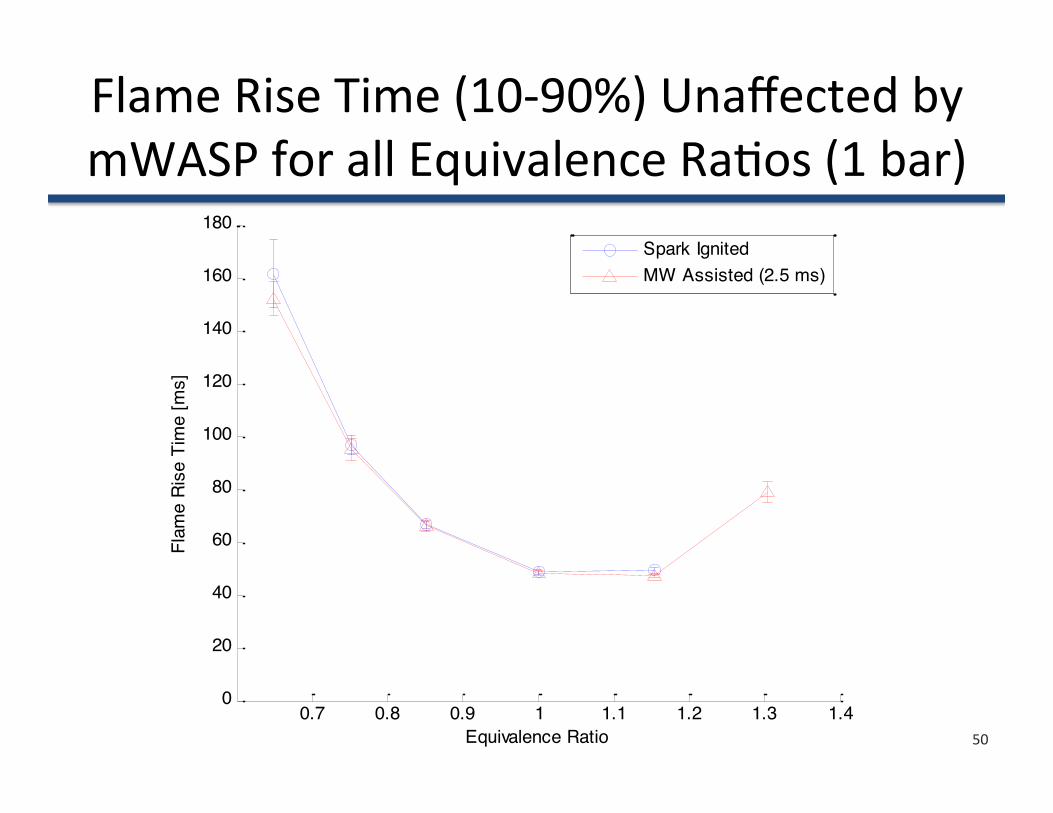
Flame Rise Time (10-‐90%) Unaffected by mWASP for all Equivalence Ra<os (1 bar)
50 0.7 0.8 0.9 1 1.1 1.2 1.3 1.4
0
20
40
60
80
100
120
140
160
180
Equivalence Ratio
Flam
e Ri
se T
ime
[ms]
Spark IgnitedMW Assisted (2.5 ms)

0.5 1 1.5 2 2.5 3 3.5 4 4.5 5 5.50
10
20
30
40
50
60
70
80
90
Initial Pressure [bar]
Flam
e De
velo
pmen
t Tim
e [m
s]
Spark IgnitedMW Assisted (2.5 ms)
mWASP Enhancement of FDT (0-‐10%) diminishes with Pressure
51
φ = 0.75
φ = 1.0
4 bar limit !

Boosted HCCI for High Power Output Using Ion Sensing for Ringing Detec>on
Robert Dibble Samveg Saxena
University of California
at Berkeley
Argonne Na+onal Laboratory
August 29, 2011

Argonne National Laboratory – August 29, 2011 Bob Dibble, Sam Saxena - Berkeley 53
Transporta+on in the 1800s
Most vehicles had 1 HP Exhaust emissions
1000X higher than today’s vehicles
New jobs to deal with “exhaust”
Lot’s of noise, and a foul odor
Growing horse-‐fuel takes up 1/3 of available cropland
Source: www.histografica.com

Argonne National Laboratory – August 29, 2011 Bob Dibble, Sam Saxena - Berkeley 54
The Limits Constraining HCCI Power Output
0
1
2
3
4
5
6
7
8
0 5 10 15
Gross IMEP
(Bar)
Combustion Timing, CA50 (deg. ATDC)
Phi=0.25 Phi=0.30
Phi=0.35 Phi=0.40
Phi=0.45 Phi=0.50
0.50
0.45
0.40
0.35
0.300.25
Ringing Limited Zone
Low Intake
T &
Misfire Limited Zone
Peak Pressure limited zone
Higher Intake Pressure
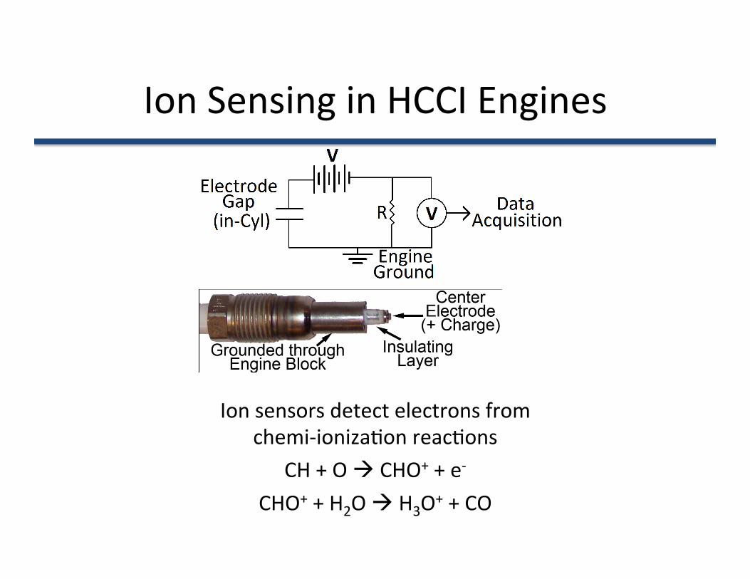
Ion Sensing in HCCI Engines
Ion sensors detect electrons from chemi-‐ioniza<on reac<ons
CH + O CHO+ + e-‐
CHO+ + H2O H3O+ + CO

Ion sensing vs. Pressure sensing Require a sensor for detec<ng
combus<on <ming
Pressure Sensing • Global measurement
• Expensive
Ion Sensing • Local measurement • Inexpensive

Ion Sensing ineffec<ve at low ϕ, but useful for ringing
• Ion sensors can effec<vely detect combus<on <ming in HCCI for control
• Ineffec<ve at low equivalence ra<o, where there is a low concentra<on of ionized species
– Saxena, et al. Increasing signal-‐to-‐noise ra<o of sparkplug ion sensors…, 33rd Interna<onal Combus<on Symposium
• Ringing occurs at higher equivalence ra<os -‐ Ion signal useful for detec<ng ringing
– Saxena, et al. Characteriza<on of HCCI ringing behavior using ion sensors, accepted for 2011 SAE Powertrains, Fuels, Lubricants Mee<ng -‐ SAE 2011-‐01-‐1777

Please Bring Your “Out of the Box” Ideas to the High Pressure Combus<on Workshop
High Pressure Combus<on Workshop At Argonne Na<onal Laboratories
Aug 2011
Robert W. Dibble UC Berkeley
Funded by DoE and KAUST

Buy This Book !

REVIEW 1…Need to be hot, to have OH radicals, OH needs to Burn out fuel before OH can burn out CO CO+OH = CO2 + H 2…do not be too hot ! You will make NO 3…Do not be too cold ! need to be hot enough to have OH to react with CO 4…buy the book !

0
10
20
30
40
50
60
70
80
-‐10 0 10 20 30 40
Pressure (B
ar)
Crank Angle Degree (CAD ATDC)
PressureIon
Ringing
Require effec<ve sensing to avoid ringing damage to an engine
Ringing – pressure waves coinciding with excessive heat release rates
Can damage an engine over <me – ECU must measure ringing intensity
Most acous<c wave energy near 5 to 6 kHz (dampened by cylinder block/lining, thus require in-‐cylinder sensor)
Pressure pulsa<ons can be order of magnitude larger than knocking

Argonne National Laboratory – August 29, 2011 Bob Dibble, Sam Saxena - Berkeley 62
Ringing Intensity vs. Ion Ringing Intensity
2
max
max
Ion
Ion RI
in
atm
P dP dtIon
α⎛ ⎞⋅ ⋅⎜ ⎟⎝ ⎠≈
2
maxmax
max
1RI2
dPdt RTP
βγ
γ
⎛ ⎞⎜ ⎟⎝ ⎠≈
Ringing Intensity
Ion Ringing Intensity
J.A. Eng SAE 2002-‐01-‐2859
Requires expensive in-‐cylinder P sensing
S. Saxena SAE 2011-‐01-‐1777
No in-‐cylinder P required

Argonne National Laboratory – August 29, 2011 Bob Dibble, Sam Saxena - Berkeley 63
Power output increases with higher Pin, max at intermediate CA50
ϕ=0.45, 1800 RPM Overall Trends:
IMEP increases with higher Pin
IMEP is highest at intermediate CA50s
0
1
2
3
4
5
6
7
8
0 5 10 15
Gross IMEP
(Bar)
Combustion Timing, CA50 (deg. ATDC)
Pin=1.0 Pin=1.2
Pin=1.4 Pin=1.6
Pin=1.8 Pin=2.0
2.0
1.81.6
1.41.2
1.0

Argonne National Laboratory – August 29, 2011 Bob Dibble, Sam Saxena - Berkeley 64
Ringing becomes a more significant constraint at higher Pin ϕ=0.45, 1800 RPM
Overall Trends:
Ringing decreases with lower Pin
Ringing decreases with delayed CA50
0
5
10
15
20
25
0 5 10 15
Ringing In
tensity
(MW/m
2 )
Combustion Timing, CA50 (deg. ATDC)
Pin=1.0 Pin=1.2
Pin=1.4 Pin=1.6
Pin=1.8 Pin=2.0
2.01.8
1.6
1.4
1.2
1.0 Ringing Limit

Out of the Box
65 Benjamin Wolk – UC Berkeley