2011_four pid controllers%2c torque distribution
TRANSCRIPT
8/17/2019 2011_Four PID Controllers%2c Torque Distribution
http://slidepdf.com/reader/full/2011four-pid-controllers2c-torque-distribution 1/4
Electronic Differential Speed Steering Control
for Four In-wheel Motors Independent Drive Vehicle*
Li Zhai, Shouquan Dong
School of Mechanical and Vehicular Engineering
Beijing Institute of Technology
Beijing 100081, China
* This work is partially supported by NSF Grant #50975027 and BIT Research Foundation #CX01008.
Abstract - Study all-wheel steering control strategy of electronic
differential speed for four in-wheel motors independent drive
vehicle. According to kinematics of steering, a dynamics model of
three degrees-of-freedom steering is established, and a control
system of electronic differential speed for four in-wheel motors
independent drive is proposed. A comprehensive control strategy
of speed and torque based on Neural Networks PID electronic
differential is proposed to calculate object speed of four wheels.
Four PID controllers are used to achieve torque distribution on
four in-wheel motors, to realize electronic differential speed
steering. The simulation results with different reference steering
angle and velocity indicate that the strategy can improve the
steering maneuvering and stability of vehicle in a low speed.
Index Terms - In-wheel motor, Independent drive, All wheel
steering, Electronic differential.
Gearbox, retarder, differential and steering mechanism are
canceled from the four in-wheel motors independent drive
vehicle. So it has flexible layout and efficient transmission
system. Using four in-wheel motors independently to drive
four driving wheels, while electronic differential speed
controls the speed and torque of the four driving wheels, then
steering of the vehicle is achieved. The strategy of electronic
differential speed control is a technological difficulty of
vehicle steering. Most researches on electronic differential
speed control are combined with the Ackerman model of
steering kinematics, and coordinate the control for speed or
torque of the four in-wheel motors[1]. If speed control alone is
used in steering, the degree of freedom of the vehicle would
decrease and the maneuvering would become worse[2]; If
torque control alone is used in steering, the stability would
become worse[3]. In order to raise vehicle maneuvering in low
speed and stability in high speed, in this paper, based on the
Ackerman model of steering kinematics and the three DOF
model of kinematics, and combined with driving motors’
controlling characteristic. Research on the electronic
differential speed steering control strategy for four in-wheel
motors independent drive vehicle is performed to verify
rationality of this method by simulation.
I. ANALYSIS OF ELECTRONIC DIFFERENTIAL SPEED
STEERING
A. Analysis of steering Kinematics
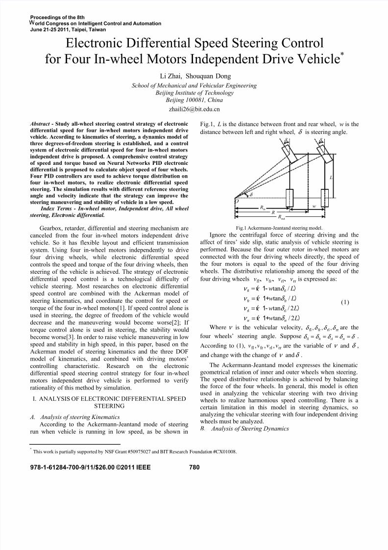
According to the Ackermann-Jeantand mode of steering
run when vehicle is running in low speed, as be shown in
Fig.1, L is the distance between front and rear wheel, w is the
distance between left and right wheel, δ is steering angle.
δ δ
w
L
O
δ
in R
out R
R
Fig.1 Ackermann-Jeantand steering model.
Ignore the centrifugal force of steering driving and the
affect of tires’ side slip, static analysis of vehicle steering is
performed. Because the four outer rotor in-wheel motors are
connected with the four driving wheels directly, the speed of
the four motors is equal to the speed of the four driving
wheels. The distributive relationship among the speed of the
four driving wheels rr rlfr fl vvvv 、、、 is expressed as:
fl fl
fr fr
rl rl
rr rr
tan /tan /
tan / 2
tan / 2
w Lw L
w L
w L
ν ν δ ν ν δ
ν ν δ
ν ν δ
==
=
=
( 1- )( 1+ )
( 1- )
( 1+ )
(1)
Where ν is the vehicular velocity, rr rlfr fl ,,, δ δ δ δ are the
four wheels’ steering angle. Supposefl fr rl rr δ δ δ δ δ = = = = .
According to (1), rr rlfr fl ,,, vvvv are the variable of ν and δ ,
and change with the change of ν andδ .
The Ackermann-Jeantand model expresses the kinematicgeometrical relation of inner and outer wheels when steering.The speed distributive relationship is achieved by balancing
the force of the four wheels. In general, this model is oftenused in analyzing the vehicular steering with two drivingwheels to realize harmonious speed controlling. There is acertain limitation in this model in steering dynamics, soanalyzing the vehicular steering with four independent drivingwheels must be analyzed.
B. Analysis of Steering Dynamics
Proceedings of the 8th
orld Congress on Intelligent Control and Automation
June 21-25 2011, Taipei, Taiwan
978-1-61284-700-9/11/$26.00 ©2011 IEEE 780
8/17/2019 2011_Four PID Controllers%2c Torque Distribution
http://slidepdf.com/reader/full/2011four-pid-controllers2c-torque-distribution 2/4
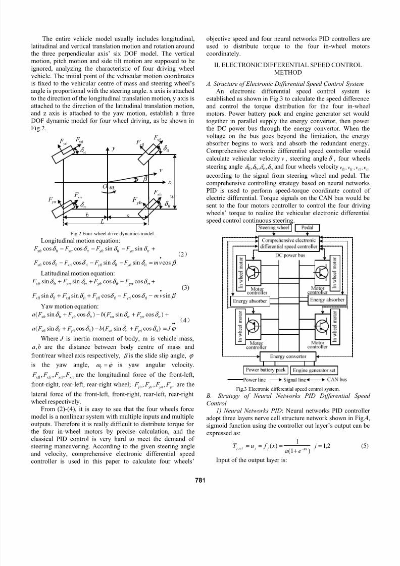
The entire vehicle model usually includes longitudinal,
latitudinal and vertical translation motion and rotation aroundthe three perpendicular axis’ six DOF model. The verticalmotion, pitch motion and side tilt motion are supposed to be
ignored, analyzing the characteristic of four driving wheel
vehicle. The initial point of the vehicular motion coordinatesis fixed to the vehicular centre of mass and steering wheel’s
angle is proportional with the steering angle. x axis is attached
to the direction of the longitudinal translation motion, y axis isattached to the direction of the latitudinal translation motion,and z axis is attached to the yaw motion, establish a three
DOF dynamic model for four wheel driving, as be shown in
Fig.2.
flδ
fr δ
rlδ
rr δ
xfl F yfl F xrl F
yrl F
xfr F xrr
F yrr F
β
v
Or ω
ab L
w
x
y
yfr F
Fig.2 Four-wheel drive dynamics model.
Longitudinal motion equation:
xfr fr xrr rr yfr fr yrr rr
xfl fl xrl rl yfl fl yrl rl
cos cos sin sin
cos cos sin sin cos
F F F F
F F F F mv
δ δ δ δ
δ δ δ δ β •
− − − +
− − − =
(2)
Latitudinal motion equation:
xfr fr xrr rr yfr fr yrr rr
xfl fl xrl rl yfl fl yrl rl
sin sin cos cos
sin sin cos cos sin
F F F F
F F F F mv
δ δ δ δ
δ δ δ δ β
•
+ + − +
+ + − =
(3)
Yaw motion equation:
xfr fr yfr fr xrr rr yrr rr
xfl fl yfl fl xrl rl yrl rl
( sin cos ) ( sin cos )
( sin cos ) ( sin cos )
a F F b F F
a F F b F F J
δ δ δ δ
δ δ δ δ ϕ ••
+ − + +
+ − + =
(4)
Where J is inertia moment of body, m is vehicle mass,
,a b are the distance between body centre of mass and
front/rear wheel axis respectively, β is the slide slip angle, ϕ
is the yaw angle, ϕ ω =r is yaw angular velocity.
xfl xfr xrl xrr , , , F F F F are the longitudinal force of the front-left,
front-right, rear-left, rear-right wheel;yfl yfr yrl yrr
, , , F F F F are the
lateral force of the front-left, front-right, rear-left, rear-rightwheel respectively.From (2)-(4), it is easy to see that the four wheels force
model is a nonlinear system with multiple inputs and multiple
outputs. Therefore it is really difficult to distribute torque forthe four in-wheel motors by precise calculation, and the
classical PID control is very hard to meet the demand ofsteering maneuvering. According to the given steering angle
and velocity, comprehensive electronic differential speed
controller is used in this paper to calculate four wheels’
objective speed and four neural networks PID controllers are
used to distribute torque to the four in-wheel motorscoordinately.
II. ELECTRONIC DIFFERENTIAL SPEED CONTROL
METHOD
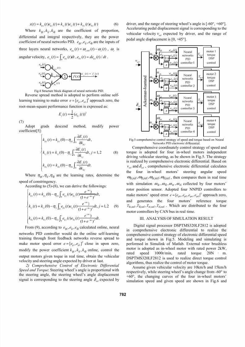
A. Structure of Electronic Differential Speed Control System
An electronic differential speed control system is
established as shown in Fig.3 to calculate the speed differenceand control the torque distribution for the four in-wheel
motors. Power battery pack and engine generator set would
together in parallel supply the energy convertor, then power
the DC power bus through the energy convertor. When the
voltage on the bus goes beyond the limitation, the energy
absorber begins to work and absorb the redundant energy.
Comprehensive electronic differential speed controller would
calculate vehicular velocity v , steering angle δ , four wheels
steering angle rr rlfr fl ,,, δ δ δ δ and four wheels velocityrr rlfr fl ,,, vvvv
according to the signal from steering wheel and pedal. The
comprehensive controlling strategy based on neural networks
PID is used to perform speed-torque coordinate control of
electric differential. Torque signals on the CAN bus would besent to the four motors controller to control the four driving
wheels’ torque to realize the vehicular electronic differential
speed control continuous steering.
Fig.3 Electronic differential speed control system.
B. Strategy of Neural Networks PID Differential SpeedControl
1) Neural Networks PID: Neural networks PID controller
adopt three layers nerve cell structure network shown in Fig.4,
sigmoid function using the controller out layer’s output can be
expressed as:
,ref ax
1( )
(1 ) j j j
T u f xa e−
= = =+
2,1= j (5)
Input of the output layer is:
781
8/17/2019 2011_Four PID Controllers%2c Torque Distribution
http://slidepdf.com/reader/full/2011four-pid-controllers2c-torque-distribution 3/4
p p i i d d( ) ( ) ( ) ( ) ( ) ( ) ( ) j j j j j j x t k t e t k t e t k t e t = + + (6)
Where j j j k k k di p ,, are the coefficient of proportion,
differential and integral respectively, they are the power
coefficient of neural networks PID. j j j eee di p ,, are the inputs of
three layers neural networks, p ,ref ( ) ( ) ( ) j j je t t t ω ω = − , jω is
angular velocity,i p
0( ) ( )
t
j je t e t dt = ∫ ,
d p( ) ( ) /
j je t de t dt = .
p( )
j t k
i( )
j t k
d( )
j t k
∑ )( x f ( ) ( )
j ju t f x=)(
p t e
j
)( p
t e j
)( p t e j
Fig.4 Structure block diagram of neural networks PID.
Reverse spread method is adopted to perform online self-
learning training to make errorT
p1 p2[ , ]e e e= approach zero, the
root-mean-square performance function is expressed as:
2
p
1( ) ( ( ))
2 j j E t e t =
(7)Adopt grads descend method, modify power
coefficient[5]:
p p p0
p
i i i0
i
d d d0
d
( )( ) (0) ,
( )( ) (0) , 1,2
( )( ) (0) .
t j
j j j
j
t j
j j j
j
t j
j j j
j
E t k t k dt
k
E t k t k dt j
k
E t k t k dt
k
η
η
η
⎧ ∂= −⎪
∂⎪⎪ ∂⎪
= − =⎨∂⎪
⎪ ∂⎪ = −⎪ ∂⎩
∫
∫
∫
(8)
Where j j j di p ,, η η η are the learning rates, determine the
speed of constringency.According to (5)-(8), we can derive the followings:
ax
p p p p p ax 20
ax
i i i p i ax 20
ax
d d d p d ax 20
)( ) (0) ( ) ( ) ,
(1 )
)( ) (0) ( ) ( ) , 1,2
(1 )
)( ) (0) ( ) ( ) .
(1 )
t
j j j j j
t
j j j j j
t
j j j j j
ek t k e t e t dt
e
ek t k e t e t dt j
e
ek t k e t e t dt
e
η
η
η
−
−
−
−
−
−
⎧= −⎪
+⎪⎪⎪
= − =⎨+⎪
⎪= −⎪
+⎪⎩
∫
∫
∫
(9)
From (9), according to j j j eee di p ,, calculated online, neural
networks PID controller would do the online self-learning
training through front feedback networks reverse spread to
make motor speed error T p1 p2[ , ]e e e= close in upon zero,
modify the power coefficient j j j k k k di p ,, online, control the
output motors given toque in real time, obtain the vehicular
velocity and steering angle expected by driver at last.
2) Comprehensive Control of Electronic DifferentialSpeed and Torque: Steering wheel’s angle is proportional with
the steering angle, the steering wheel’s angle displacement
signal is corresponding to the steering angleref
δ expected by
driver, and the range of steering wheel’s angle is [-60°, +60°].
Accelerating pedal displacement signal is corresponding to the
vehicular velocityref
v expected by driver, and the range of
pedal angle displacement is [0, +45°].
1/ s
s
1/ s
s
1/ s
s
1/ s
s
ref v
ref δ
ref fl,ω rflω
ref fr,ω rfr
ref rl,ω
rrlω
ref rr,
rrr ω
fle
fr e
rle
rr e
)( pfl t e
)(ifl t e
)(dfl
t e
)( pfr t e
)(ifr t e
)(dfr t e
)( prl t e
)(irl t e
)(drl t e
)( prr
t e
)(irr
t e
)(drr t e
ref fl,T
ref fr,T
ref rl,T
ref rr,T
Fig.5 comprehensive control strategy of speed and torque based on Neural
Networks PID electronic differential.
Comprehensive coordinately control strategy of speed and
torque is adopted for four in-wheel motors independent
driving vehicular steering, as be shown in Fig.5. The strategy
is realized by comprehensive electronic differential. Based on
ref v and ref δ , comprehensive electronic differential calculates
the four in-wheel motors’ steering angular speed
ref ,rlref ,rr ref ,flref ,fr ,,, ω ω ω ω , then compares them in real time
with simulation rlrr flfr ,,, ω ω ω ω collected by four motors’
rotor position sensor. Adopted four NNPID controllers to
make motors’ speed error T pfr pfl prr prl[ , , , ]=e e e e e approach zero,
and generates the four motors’ reference torque
ref ,rlref ,rr ref ,flref ,fr ,,, T T T T . Which are distributed to the four
motor controllers by CAN bus in real time.
III. ANALYSIS OF SIMULATION RESULT
Digital signal processor DSPTMS320LF2812 is adopted
in comprehensive electronic differential to realize thecomprehensive control strategy of electronic differential speed
and torque shown in Fig.5. Modeling and simulating is
performed in Simulink of Matlab. External rotor brushlessmotor is adopted as in-wheel motor with rated power 2kW,
rated speed 1000r/min, rated torque 20N · m.
DSPTMS320LF2812 is used to realize direct torque controlalgorithms, thus realize the control of motor torque.
Assume given vehicular velocity are 10km/h and 15km/h
respectively, while steering wheel’s angle change from -60° to
+60°, the changing curves of the four in-wheel motors’simulation speed and given speed are shown in Fig.6 and
782

8/17/2019 2011_Four PID Controllers%2c Torque Distribution
http://slidepdf.com/reader/full/2011four-pid-controllers2c-torque-distribution 4/4
Fig.7, Curves of speed difference between front wheels and
between rear wheels are shown in Fig.8 and Fig.9. It can bedrawn from Fig.6 and Fig.7 that there is obvious speed
difference between left and right wheels, the speed of the two
rear wheels is lower than the speed of the two front wheels,the changing rule of the four wheels speed and the theoreticalanalysis are consistent. From Fig.8 and Fig.9, it can be drawn
that accompany with the increase of vehicle speed and
direction angle, speed difference become bigger and speeddifference between two rear wheels is smaller than it betweentwo front wheels. In addition, there is a certain error between
the motors’ simulation speed and given speed, the error is
quite big at the beginning of start-up, it become smallgradually after regulated by NNPID comprehensive control
strategy, and the output of speed is relatively stable.
(a) front right wheel
(b) front left wheelFig.6 Curves of speed difference between right and left front-wheel with
different speed and steering angle.
(a) rear right wheel
(b) rear left wheelFig.7 Curves of speed difference between right and left rear-wheel with
different speed and steering angle.
Fig.8 Curves of speed difference between right and left front-wheel withdifferent speed and steering angle.
Fig.9 Curves of speed difference between right and left rear-wheel withdifferent speed and steering angle.
IV. CONCLUSION
The three DOF steering dynamics model of the four in-wheel motors independent driving vehicle is a nonlinear
system with multiple inputs and multiple outputs. The
comprehensive control strategy which based on neural
networks PID control electronic differential speed speed-torque is adopted to distribute torque to the four in-wheel
motors coordinately. The results of simulation indicate that the
control strategy is feasible and reasonable.
Motor’s control properties can affect vehicular steering
properties directly, therefore the four in-wheel motorsindependent driving vehicle should adopt motors and motor
controllers with high control properties. Electronic differential
speed control strategy should combine with motor controlstrategy to make optimization and perfection in order to meet
the requirement of vehicular steering properties.
R EFERENCES
[1] GE Yinghui and NI Guangzheng, “Novel electric differential controlscheme for electric vehicles,” J . Journal of Zhejiang University(Engineering Science), vol. 39(12), pp. 1973-1978, 2005. (in Chinese)
[2] Jin Liqiang, Wang Qingnian and ZHOU Xuehu, “Control strategy andsimulation for electronic differential of vehicle with motorized wheels,”
J . Journal of Jilin University (Engineering and Technology Edition),
vol.18, pp. 1-6, 2008. (in Chinese)
[3] ZHOU Yong, LI Shengjin and TIAN Haibo, “Control method ofelectronic differential of EV with four in-wheel motors,” J . Electric
Machines and Control , vol. 11(5), pp.467-471, 2007. (in Chinese)[4] US Chong, E Namgoong and SK Sul, “Torque steering control of 4-
wheel drive electric vehicle,” J . Power Electronics in Transportation, pp.159-164, 1996.
[5] Thanh T.D.C and Ahn K.K , “ Nonlinear PID control to improve thecontrol performance of axes pneumatic artificial muscle manipulator
using neural network,” J . Mechatronics, vol.16, pp.577-587, 2006.
-60 -40 -20 0 20 40 60 -150
-100
-50
0
50
10
15
δ(°)
v=15km/h
v=10km/h
Reference△n
Simulation△n
-60 -40 -20 0 20 40 60 -300
-200
-100
0
100
200
300
400
δ(°)
Reference△n
Simulation△n
v=15km/h
v=10km/h
-60 -40 -20 0 20 40 60-50
0
50
100
150
200
250
δ(°)
s p e e d r l ( r / m i n )
v=15km/
v=10km/h
Reference speed
Simulation speed
-60 -40 -20 0 20 40 60 -50
0
50
100
150
200
250
300
δ(°)
S p e e d r r ( r
/ m i n )
Reference speed
Simulation speed
v=15km/
v=10km/h
-60 -40 -20 0 20 40 60 -50
0
50
100
150
200
250
300
δ(°)
Reference speed
Simulation speed
v=15km/h
v=10km/h
-60 -40 -20 0 20 40 60
-50
0
50
100
150
200
250
δ(°)
s p e e d f r ( r / m i n )
Reference speed
Simulation speedv=15km/h
v=10km/h
S p e e d f l ( r / m i n )
s p e e d △ n ( r / m i n )
s p e e d △ n ( r / m i n )
783