telesafe pid controllers - dashboard - schneider electric...
TRANSCRIPT

TelePACE PID ControllersReference Manual
CONTROLMICROSYSTEMSSCADA products... for the distance
28 Steacie Drive Telephone: 613-591-1943Kanata, Ontario Facsimile: 613-591-1022K2K 2A9 Technical Support: 888-226-6876Canada 888-2CONTROL

TelePACE PID Controller Reference Manual©1994 - 1999 Control Microsystems.All rights reserved.
Printed in Canada.
TrademarksSmartWIRE is a registered trademark of Control Microsystems.
SCADAPack is a registered trademark of Control Microsystems.
TeleSAFE is a registered trademark of Control Microsystems.
All other product names are copyright and registered trademarks or trade names of theirrespective owners.

Table of Contents i
Table of Contents
OVERVIEW...................................................................................................................1
INTRODUCTION TO PID CONTROL..........................................................................2
Proportional Control .................................................................................................2On/Off Control ......................................................................................................4
Proportional-Integral Control .....................................................................................4Proportional-Integral-Derivative Control ....................................................................6Cascade Control........................................................................................................8
Jacketed Vessel Control .........................................................................................8Ball Mill Control ....................................................................................................8
Ratio/Bias Control .....................................................................................................9Time Proportioned Outputs.......................................................................................9Square Root Linearization .......................................................................................11
Square Root Normalization..................................................................................11
INTRODUCTION TO CONTROL BLOCKS ................................................................12
Control Block Characteristics...................................................................................12Background Operation ........................................................................................12Independent Sample Times..................................................................................13Application Program Access ................................................................................13Anti-Integral Windup ...........................................................................................13Output Limiting ...................................................................................................13Square Root Extraction.........................................................................................13External Execution Inhibit ....................................................................................13Automatic Alarm Scanning ..................................................................................13Deadband............................................................................................................13
ACCESSING CONTROL BLOCKS ...............................................................................14
C Language Functions .............................................................................................14Setting Individual Bits ..........................................................................................15Clearing Individual Bits........................................................................................15
Ladder Logic Functions ...........................................................................................15
CONTROL BLOCK VARIABLES ..................................................................................17
Variable Descriptions ..............................................................................................18Alarm Output Address - AO.................................................................................18Cascaded Setpoint Source - CA............................................................................18Control Register - CR ...........................................................................................18Deadband - DB....................................................................................................18Decrease Output - DO.........................................................................................19Error - ER .............................................................................................................19Full Scale Output - FS ..........................................................................................20

Table of Contents ii
Gain - GA............................................................................................................20High Alarm Level - HI..........................................................................................20Input Bias - IB ......................................................................................................20Inhibit Execution Input - IH..................................................................................21Integrated Error - IN .............................................................................................21Increase Output - IO............................................................................................22Input Source - IP ..................................................................................................22Low Alarm Level - LO..........................................................................................23Output Bias - OB .................................................................................................23Output Quantity - OP ..........................................................................................24Process Value - PV...............................................................................................24Rate Time - RA.....................................................................................................24Reset Time - RE....................................................................................................24Setpoint - SP ........................................................................................................24Status Register - SR...............................................................................................25Zero Scale Output - ZE ........................................................................................25
CONTROL BLOCK INPUT CONCEPTS ......................................................................26
Constant Block Inputs..............................................................................................26Process Simulation...............................................................................................26Signal Conditioning .............................................................................................26
Analog Block Inputs ................................................................................................27Input Channel Block Inputs..................................................................................27Output Channel Block Inputs...............................................................................27
Block Output Block Inputs ......................................................................................27Stream Blending Control......................................................................................27Output Tracking ..................................................................................................27
CONTROL BLOCK OUTPUT CONCEPTS ..................................................................28
Block Output Types.................................................................................................28Analog Outputs ...................................................................................................28Time Proportioned Outputs .................................................................................28Dummy Analog Outputs......................................................................................30
Output Limiting.......................................................................................................30Zero Scale Output Limit.......................................................................................31Full Scale Output Limit ........................................................................................31Analog Block Output Limits.................................................................................31Time Proportioned Output Limits ........................................................................31Dummy Analog Output Limits .............................................................................32Internal Block Output Limits ................................................................................32
CONTROL BLOCK SETPOINT CONCEPTS ................................................................33
Constant Setpoints...................................................................................................33Cascaded Setpoints .................................................................................................33Remote Block Setpoints...........................................................................................33Ramping Setpoints...................................................................................................34
CONTROL REGISTER .................................................................................................35
Block Alarms...........................................................................................................36

Table of Contents iii
Absolute Level Alarm...........................................................................................36Deviation Alarm ..................................................................................................36Rate Of Change Alarm.........................................................................................37
Manual Mode..........................................................................................................37Setpoint Tracking ....................................................................................................37I/O Specification .....................................................................................................37
Controllers with Firmware v. 1.23 or Newer ........................................................38Controllers with Firmware v. 1.22 or Older .........................................................38
STATUS REGISTER .....................................................................................................39
Alarm Acknowledge Bit...........................................................................................39
CONTROL BLOCK EXECUTION ................................................................................41
Non-bumpless Engagement .....................................................................................41Bumpless Engagement.............................................................................................41
C Language Procedure.........................................................................................42Ladder Logic Procedure .......................................................................................42
Minimum Execution Periods....................................................................................42
CONFIGURING CONTROL BLOCKS.........................................................................44
Register Assignment ................................................................................................44Configuring PID Controllers ....................................................................................44
Analog Output.....................................................................................................44Time Proportioned Output...................................................................................47
Configuring Ratio/Bias Controllers...........................................................................50Configuring Cascade Controllers .............................................................................51
Configuring the Primary Controller ......................................................................52Configuring the Secondary Controller ..................................................................52
Configuring Automatic Alarms ................................................................................53Disabling Automatic Alarms ................................................................................54
CONFIGURATION EXAMPLES...................................................................................56
Alarms: High Alarm.................................................................................................57Alarms: High and Low Alarms.................................................................................58PID Control: Analog Output ....................................................................................58PID Control: Analog Output and Alarms .................................................................60PID Control: Single Acting Time Proportioned Output.............................................61PID Control: Dual Acting Time Proportioned Output ..............................................62PID Control: Cascade Controllers ............................................................................63PID Control: Square Root Linearization for Flow Control.........................................66Output Tracking ......................................................................................................67Ratio Control...........................................................................................................68Batch Control ..........................................................................................................69

Table of Contents iv
TUNING PID CONTROL BLOCKS.............................................................................71
Closed Loop Tuning: The Ziegler-Nichol Method ....................................................71Open Loop Tuning: The Cohen-Coon Method.........................................................72Fine Tuning.............................................................................................................73Selecting the Execution Period ................................................................................74
PID or Ratio/Bias Controllers ...............................................................................74Time Proportioned Output Controllers.................................................................74
ADVANCED CONTROL .............................................................................................75
The Digital Computer and Discrete Control.............................................................75Programming Algorithms.........................................................................................75
APPENDIX A: TRANSFER FUNCTION........................................................................78

Overview 1
Overview
The PID (Proportional, Integral, Derivative) control algorithm has been used forfeedback control systems since the turn of the century. Traditionally,pneumatic controllers were used to perform this algorithm. Though easy to use,they are limited as to the additional functions that can be performed.
Electronic PID controllers expanded the versatility of the feedback system byincorporating additional functions into the PID algorithm. The low costmicrocomputer expanded the potential for feedback control immensely, withalgorithms limited only by the imagination of the programmer.
SCADAPack and TeleSAFE controllers employ a firmware PID algorithm thatfeatures the ease of use of the pneumatic controller, with the full control powerof a computerized system. The controllers can service completely the controlrequirements of many industrial and bench scale applications. The PID controlblocks are not limited to the PID control algorithm. They also provide ratiocontrol, ratio/bias control, alarm scanning and square root functions. Controlblocks may be interconnected to exchange setpoints, output limits, and otherparameters.
PID control blocks operate independent of application programs. A elaboratecontrol program need not be written to use the control blocks. A simpleprogram to set up the control blocks is all that is required.
The main objectives of this manual are presenting how PID and ratiocontrollers are utilized in SCADAPack and TeleSAFE controllers, and guidingthe user in their application. It is assumed that the reader already has anunderstanding of control theory. However, the rudiments of the PID algorithmare discussed to refresh the memories of experts and to introduce the conceptsfor those who are unfamiliar with the PID algorithm. Several rudimentarycontrol schemes are discussed as well. Two techniques for tuning the PIDcontrollers are presented. For experienced users, a section on implementingadvanced control algorithms is included.
We have endeavored, as much as is possible, to present a clear, concise guideto the control blocks in controller. Everyone, including those familiar withother Control Microsystems products, should read this manual at least once, asconcepts unique to the control blocks in the controller are discussed. Newusers are encouraged to read the manual twice, so that the more difficultconcepts become clearer. A thorough study of the manual will enable you toextract the full potential of your controller.

Introduction to PID Control 2
Introduction to PID Control
An automatic control system regulates a process by manipulating a controlelement through the feedback of a controlled output. The common householdthermostat is an example of feedback control. The room temperature iscompared to the temperature setting and a decision is made to turn the furnaceon or off. The room temperature is known as the process value and thetemperature setting is known as the setpoint. The furnace, in this case, is thecontrol element.
A block diagram of a typical feedback control loop is shown in Figure 1. Thesetpoint is fed into a comparator for comparison to the process value. For thehousehold thermostat, the process value is the temperature of the house. Thecontrol algorithm makes the decision and generates the control output. Theprocess is affected by the control output, resulting in a change in the processvalue. Ultimately, the process output will change sufficiently that the processvalue will approach the setpoint value.
ControlAlgorithm Process
processvalue
processvalue
outputerrorsetpoint
optional
+
–
Figure 1: Typical Feedback Control Loop
Process control in the chemical processing industry has been used since theturn of the century, but efforts to understand feedback control were notextensive until the 1920's. The laying of the Trans-Atlantic communicationscable necessitated the development of predictable and reliable transmissioncontrol. The foundations of modern control theory were set in this era.
The product of the original research in transmission control is the Proportional-Integral-Derivative (PID) controller that is now used extensively for industrialfeedback control. In this chapter, the theory of the PID controller is explained.Rather than treating PID as a single entity, P, PI and PID controllers arediscussed to illustrate the effect of each element. The development of the PIDalgorithm is explained step by step to provide a general understanding for thereader.
Proportional ControlThe proportional controller produces an output that is proportional to thedifference between the setpoint and the process value. This difference iscommonly referred to as the error. The greater the error, the greater the outputof the controller. The equation for the output from a proportional controller isgiven as:
m K e ms= × + Equation 1
where: m is the controller outputK is the gain

Introduction to PID Control 3
e is the error1 = setpoint – process valuems is a constant
The error term is calculated as the difference of the setpoint and the processvalue. Thus, these two values must be measured in the same units.
K is the controller's proportional gain. It is the adjustable parameter in thecontroller that enables it to be tuned. By adjusting the gain, the magnitude ofthe control output can be changed for a given error. The parameter ms is equalto the steady state output required to produce an error of zero. When the erroris zero, it can be seen from equation 1 that the controller output is necessarilyequal to ms. Thus, the steady-state error in a process controlled by aproportional controller is equal to zero if there are no changes in the process.
A problem arises with proportional control when a disturbance is introduced tothe process. Disturbances result in a steady-state error (ess) as shown in Figure2. The best way to explain the effect of a disturbance is through the followingexample.
ess
timet1
setpoint
processvalue
timet1
ms
output
ProcessValueResponse
ControllerOutputResponse
Figure 2: Proportion Controller Response
Example:A proportional controller is used to control the temperature of a house. Theconstant ms has been chosen so that the house temperature is 21°C. With thisvalue of ms there is no error. Unfortunately, a window is left open on a winterday. The value of ms is insufficient to keep the temperature at 21°C resulting inan error. Since it is a proportional controller, the presence of an error causesthe output of the controller to increase by the amount K×e, but this increase isinsufficient to raise the temperature of the house to the setpoint of 21°C. Thus,a steady-state error results.
Figure 2 shows the process value and the response of a P controller to adisturbance introduced at time t1. At t1, the process value is equal to thesetpoint and the controller output is ms. The disturbance causes the process
1 See the Error section on page 19 for a full description of how the error is calculated in the PIDalgorithm on the controller.

Introduction to PID Control 4
value to fall below the setpoint. The resulting time varying error, causes thecontroller output to increase. This causes the error to decrease, but a steady-state error (ess) must persist in order to maintain the increased output of thecontroller.
Thus proportional controllers are very sensitive to disturbances, and givensufficient time and disturbances, a steady-state error will result.
On/Off ControlA special case of the proportional controller is the On/Off controller(sometimes called a bang-bang controller). As the name implies, there are onlytwo states of the output of an on/off controller – on or off. There are no in-between states. The typical household thermostat is an example of this type ofcontroller.
The equation for the on/off controller is:
m K e K= × = ∞, Equation 2
where: m is the controller outputK is the gain = ∞e is the error = setpoint – process value
This equation is similar to that of the proportional controller. The differencesare that the gain is fixed at infinity, and the constant ms is removed (since theterm K×e is so large, the term ms is essentially zero). Therefore, for any negativeerror (i.e. process value greater than setpoint) an infinitely negative outputresults; for any positive error, an infinitely positive output results.
In the case of the household thermostat, when the room is cold, the thermostatturns on the furnace and when it is warm, it turns off the furnace.
Proportional-Integral ControlA proportional controller produces a steady-state error when a disturbance isintroduced. This error can be eliminated by adding integral action to the Pcontroller. This is known as proportional-integral (PI) control.
The equation for the output of a PI controller is:
m K eKT
e dt ms= × + +� Equation 3
where: m is the controller outputK is the gaine is the error = setpoint – process valueT is the reset timems is a constant
e dt� is the integration of all previous errors
The second term in the equation is known as the integral term. The other termsof the equation are unchanged from the P controller equation.
The parameter T is an adjustable quantity that determines the amount ofintegral action in the output of the controller. The parameters K and T allow

Introduction to PID Control 5
the PI controller to be tuned. It can be seen upon inspection of equation 3 thatthe PI controller becomes a P controller as T approaches a positive infinitequantity (T cannot be negative since it measures a time quantity). As Tapproaches infinity, the integration term in the equation approaches zero.
The effect of adding integral action is to remove steady-state error. When anerror exists, it is summed (integrated) with all the previous errors, therebyincreasing or decreasing the output of the PI controller (depending uponwhether the error is positive or negative). Thus, as the error accumulates in theintegral term, the output changes so as to eliminate the error. A P controllerwill have a constant output when a steady-state error exists, therebyperpetuating the error. A PI controller reduces the steady-state error to zero,through the action of the integral term, as shown in Figure 3.
Example:The temperature regulation of the house in the previous example can beimproved by using a PI controller. If the window is opened on a cold day, apositive error results between the room temperature and the setpoint (i.e. theroom is cold). The error accumulates in the integration term and as this termgets larger the output of the controller increases. As a result of the increase inthe controller output, the room temperature increases until the setpoint isreached.
When the setpoint is reached, the error and all the subsequent errors are zeroand the integration term becomes a constant. PI control has eliminated thesteady-state error that results when a disturbance is encountered by a Pcontroller.
timet1
setpoint
processvalue
timet1
ms
output
ProcessValueResponse
ControllerOutputResponse
Figure 3: Proportional-Integral Controller Response
As a further illustration, assume that the window is now closed. Since a sourceof heat loss has been eliminated, the temperature rises above the 21°C setpointproducing negative errors. Summing these negative errors into the integral termdecreases the output of the controller. The temperature then falls until thesetpoint is reached, at which point the error and all subsequent errors are zero.When this occurs, the integral term ceases to decrease and becomes constant.

Introduction to PID Control 6
The output of the controller is constant and the room temperature remains atthe setpoint. Steady-state error has been avoided.
Figure 3 is representative of the typical response of the process and the PIcontroller to a disturbance. The steady-state error in Figure 2 is notcharacteristic of the process response when regulated by a PI controller.
A novel (though not theoretically correct) way of viewing integral action is thatit emulates the resetting of the setpoint. To see what is meant by this, considerthat the occupant of the house in the previous example has found that theroom temperature is below the desired level. The occupant is a P controllerand regulates the temperature. Rather than checking for an open window, theoccupant raises the thermostat setting every five minutes until the temperatureis 21°C. The five minute period is the setpoint reset time, hence the naming ofthe parameter T in equation 3. It is important to understand that in a PIcontroller the setpoint is not altered. The integral term takes this "setpointresetting" into account.
Proportional-Integral-Derivative ControlThe response of PI controller tends to be oscillatory. The process valuecontinuously rises above and falls below the setpoint. This is the result of theintegral action over-compensating for the error. The amplitude of theoscillations can be decreased by decreasing the proportional gain, K, or bydecreasing the amount of integral action by increasing T. This results in a muchslower response of the controller (i.e. a longer time to reach the setpoint once adisturbance has been introduced). The addition of derivative control to the PIcontroller improves the response of the controller when the gain and/or theintegral action is decreased to eliminate the oscillatory response.
The equation for the PID controller is:
m K eKT
e dt K Rdpdt
ms= × + + × × +� Equation 4
where: m is the controller outputK is the gaine is the error = setpoint – process valueT is the reset timeR is the rate gainp is the process valuems is a constant
e dt� is the integration of all previous errors
dpdt
is the rate of change of the process value
The third term in the equation is known as the derivative term, as it takes intoconsideration the rate of change of the process value. The other terms areunchanged from the PI controller.
The parameter R is the rate gain. The PID controller can be tuned to give anadequate response for any process, by adjusting the rate gain, along with theproportional gain and reset time. The derivative gain is adjusted to vary the

Introduction to PID Control 7
magnitude of the output change for a given change in the process value. R ismeasured in time units; usually seconds.
Derivative (or anticipatory) action detects a change in the process value2 andproduces an output based upon the change. If the process value suddenlyincreases, the derivative action responds to decrease the output of thecontroller so as to decrease the process value. Derivative action anticipates apermanent increase or decrease in the process value, therefore improving theresponse of the controller by rapidly applying an opposing output.
Figure 4 illustrates the response of a PID controller to a disturbance introducedat time t1. The response is quicker and less oscillatory than that of a PIcontroller. The peak in the controller response, known as the derivative peak,is caused by the sudden change in the process value.
Readers who have previously studied process control theory may havedetected that the derivative term in equation 4 has been subtracted from theequation for the PI controller rather than added, as is stated in many processcontrol textbooks. It also uses the rate of change of the process value ratherthan the rate of change of the error. Textbooks often state that these two ratesare equivalent, but this is not necessarily true.
To illustrate this point consider a process at steady-state. If the setpoint ischanged there is an instantaneous and infinite rate of change in the error; butthe rate of change of the process value is zero. Simply stated:
timet1
setpoint
processvalue
timet1
ms
output
ProcessValueResponse
ControllerOutputResponse
Figure 4: Proportional-Integral-Derivative Response
dedt
dpdt
≠ Equation 5
during a setpoint change. As a result, the output of equation 4 is less sensitiveto setpoint changes than the equation suggested by many textbooks. Also,equation 4 is much more sensitive to disturbances in the process, whereas theequation suggested in many textbooks can make the process unstable.
2 Note that this is not necessarily the same as a change in the error.

Introduction to PID Control 8
The Z-transform of equation 4 has been derived in Appendix A. A stabilityanalysis on the PID controllers of SCADAPack and TeleSAFE controllers mustbe performed using this transfer function, rather than the ones cited in mosttextbooks.
Cascade ControlCascade controllers are often used when two control loops are interrelated.One of the two loops is usually fast acting, and the other slow acting with along dead time. Usually, the slow acting controller is the primary controllerand the fast acting controller is the secondary controller. Two examples ofcontrol situations applicable to cascade control are given below.
Jacketed Vessel ControlJacketed vessels (Figure 5) are often used to control the temperature ofproducts. If the jacket volume is large relative to the tank volume, it may bevery easy to overheat or overcool the jacket contents with the result that thetemperature of the tank contents will cycle about the setpoint. Using onecontroller to maintain the jacket temperature with the setpoint of the controllerdetermined by a second product temperature controller is an effective methodto achieve accurate, high speed control.
controlvalve
PrimaryController
SecondaryController
steam
temperaturesetpoint
output
setpoint
outputprocessvalue
processvalue
temperature
to condensorand boiler
heater jacket
vessel
Figure 5: Cascade Control of Jacketed Vessel
Ball Mill ControlBall mills (Figure 6) operate best at specific ore loading levels. The loadinglevel can be measured by the current required to rotate the mill. The motorcurrent is the main controlling parameter and provides the input to the primarycontroller.
Weight belts with motor speed controls are often used to control the rate atwhich material is fed to the ball mill. The fast acting weigh belt signal forms theinput to the secondary controller. The setpoint in the secondary controller isderived from the output of the primary ball mill motor current controller.

Introduction to PID Control 9
motor
ball millfeed belt
belt motor
outputsetpoint setpoint
processvalueoutput
processvalue
SecondaryController
PrimaryController
beltspeedsensor
motor currentsensor
Figure 6: Cascade Control of a Ball Mill
Ratio/Bias ControlA ratio/bias controller sets the controller output equal to the input multipliedby a constant, plus an optional output bias. Ratio controllers are used where ananalog output must track an analog input or output signal.
Ratio/bias controllers can also be used to provide remote setpoint inputs forPID controllers. Refer to Remote Block Setpoints in the Control Block SetpointConcepts section for a description of this capability.
The equation for the ratio/bias controller is:
m K p Bo= × + Equation 5
where: m is the controller outputK is the ratio gainp is the process valueBo is the output bias
This equation is similar to that of the proportional controller. The difference isthat it is the process value rather than the error (setpoint - process value) whichis multiplied by the gain. The proportional controller will behave as a ratiocontroller if a negative gain and a setpoint of zero is used. However, forsimplicity, the ratio controller has been incorporated as a separate entity inTelePACE PID control blocks.
Ratio/bias controllers are typically used to track the output of anothercontroller. To illustrate this, consider the fuel flow rate to a furnace that iscontrolled by a PID controller. As more fuel is added, more air (in directproportion) is required for combustion. A ratio controller whose input is theoutput of the fuel flow controller will add the required air in direct proportion.
Time Proportioned OutputsThere are two possible types of output from a PID or ratio/bias controller: ananalog signal and a time proportioned digital output (sometimes called a pulseduration output). An analog output sends the controller output quantity to ananalog output module to generate an analog signal. A time proportionedoutput sends the controller output quantity indirectly to a digital output.

Introduction to PID Control 10
Simply stated, for a time proportioned output, the output of a PID controller isused to proportion a fixed time period into an "on-time" and an "off-time".During the on-time, a digital output is turned on; during the off-time the outputis turned off.
The length of the on-time is proportional to the magnitude of the controlleroutput, while the off-time is the difference between the fixed time period andthe on-time. Consequently, the time proportioned output is a train of pulses ofvarying widths where the pulse width corresponds directly to the controlleroutput.
In this way, the output simulates an analog output. Figure 7 compares a timeproportioned pulse train to an equivalent analog output. The width of the pulseis proportional to the height of the analog output at the start of each timeperiod T.
The control elements that are best suited to time proportioned outputs aredevices that can withstand frequent cycling between the on and off states. Suchdevices include solenoid valves controlling continuous flows, forward/reversemotor screws, high power electric heaters (where SCR controllers might bevery expensive), and diaphragm valves with open/close control solenoids.Although it is possible to use electric motors with this type of output, excessivewear, caused by the frequent start-ups, may result.
There are operational limitations involved in using time proportioned control.Since a timer is used to set the on-time, the resolution of the pulse output islimited by the minimum time interval of the timer. The resolution can beimproved by increasing the length of the fixed time interval that is beingpartitioned. The paradox here is that by increasing the fixed time period, thefrequency of execution of the control algorithm is decreased, which can resultin unstable response in extreme cases.
time4T3T2TT
time
AnalogOutput
TimeProportionedOutput
8T7T6T5T
4T3T2T
0%
100%
0%
100%
50%
T 8T7T6T5T
0.0T 0.8T0.50.0T0.1T0.5T0.9T0.8T 1.0T
Figure 7: Analog and Time Proportioned Outputs
ExampleConsider that the temperature of a liquid in a vessel is regulated by a PIDcontroller with a time proportioned output directed to a solenoid valve thatadmits steam to a jacket surrounding the vessel. The timer used to set the

Introduction to PID Control 11
output on-time has a resolution of 0.1 second. The fixed time period is 10seconds.
To illustrate the determination of the on-time consider that the PID controllerhas calculated an output of 30. The timer is thus loaded with 30 tenths of asecond and since a non-zero on-time is required, the digital output to thesolenoid valve is turned on.
After the timer has timed-out (after 3 seconds), the digital output is turned offfor the remainder of the time period, that is 7 seconds. Once this period haspassed, the control algorithm executes again and the cycle repeats.
Square Root LinearizationPID controllers and ratio/bias controllers assume that the process value islinear. Some methods of measurement product non-linear signals. The outputof the measurement device does not vary in a linear fashion with respect to thequantity being measured.
Consider the control of the flow rate of a liquid. The input to the controller is aheight reading from a manometer (or more commonly a differential pressurecell) installed on the piping. It can be shown that the flow rate is proportionalto the square root of the height of the manometer. The equation is:
f K p C= + Equation 6
where: f is the flow rateK is the gainp is the process value (reading from manometer)C is a constant adjusting for pump head, NPSH and pipe friction
To use the manometer reading as a process value it must be linearized, bytaking the square root, before the calculations of the PID controller or theratio/bias controller can be performed. TelePACE PID controller blocks providea square root extraction function for this purpose. If it is necessary to specifythe constant C, the control blocks provide an input bias for this purpose.
An inherent problem with this linearization is that the precision of the processvalue is no longer linear over the range of the process value. The larger theprocess value, the more precise the result of the linearization.
Square Root NormalizationThe normal input range of the process value in TelePACE PID control blocks is–32767 to 32767 I/O counts. If square root extraction is performed on thisrange, a maximum value for the process value of 181 results. Since thiseffectively reduces the resolution (though not the precision) of the input,TelePACE PID control blocks normalize the square root value, by multiplying itby 128. Thus the square root of 32767 (181) becomes 23170.
The control blocks retain the sign of the value when a square root is extracted,and calculate the root on the magnitude of the value. This allows square rootextraction on inputs whose values may be negative.

Introduction to Control Blocks 12
Introduction to Control Blocks
TelePACE PID control blocks are capable of providing the following functions,or combinations of functions:
• P, PI, PID or PD control
• multi-loop cascade control
• on/off control
• ratio control
• ratio/bias control
• square root extraction
• alarm detection with annunciation
A control block may be configured to perform any of the above operations.Some configurations permit multiple functions within a block. For instance,only one block is required for a PID controller with square root extraction andalarm level detection on the process value. Other combinations are possible.
Blocks may be interconnected to combine their functions in a larger controlscheme. For instance, multi-stream blending control can use one PID controllerto control total stream flow with any number of slave ratio controllers tocontrol the flow contributed by each stream. The same system could use otherblocks to detect alarm levels on either controller outputs or stream flows; or toturn stream pumps on or off.
An important aspect of the control blocks is that they operate in thebackground, independent of application programs. However, applicationprograms have full access to all block parameters and tuning parameters at anytime. This permits advanced control concepts such as dynamic tuning.Programs written in C or Ladder Logic can supervise control loops to optimizetheir operation. In fact, application programs can even reconfigure the blocksduring operation. For example, controllers can be set up to operate asproportional-only controllers when the error is large, and then be reconfigureto PI controllers when the error becomes smaller. This interaction between theprogram and the control blocks provides a very high degree of flexibility.
Control Block Characteristics The sections below describe the main features of the TelePACE PID controlblocks.
Background Operation Control blocks operate in real time, separate from application programs. Thisensures that time critical operations receive priority. Blocks can be set up tooperate on individual time intervals. High speed control loops can be servicedmore frequently than slower loops so as to distribute processor power where itis required. Control blocks will operate even when programs are being edited

Introduction to Control Blocks 13
Independent Sample Times Control blocks may be individually configured for ten executions per second toas few as one execution every 6553.5 seconds. Longer sample times consumefewer processor cycles, leaving more time available to application programs.
Application Program Access Application programs may read all control block tuning parameters andinternal variables, even when the controllers are executing. Likewise, aprogram may store tuning parameters and internal variables into thecontrollers. This feature permits dynamic tuning of controllers duringoperation.
Anti-Integral Windup Anti-integral windup prevents integral summation (reset operation) if theoutcome of such summation would be to set the controller output above orbelow the defined output limits.
Output Limiting Output limits may be programmed for each controller to prevent the controllerfrom generating an output that is above or below desired limits.
Square Root Extraction Controllers may be configured to calculate the square root of the process valueand/or the error. The sign (polarity) of the process value and/or error isretained. Square roots are useful when the process value is derived fromorifice-plate flow meters or other devices which exhibit a square relationship.
External Execution Inhibit Each controller may use a digital input from the I/O system to preventexecution of the controller. The controller will halt execution as long as theinput remains on.
Automatic Alarm Scanning A feature included in the control blocks (which is not related to the controlalgorithm) allows analog input channels to be monitored for levels above orbelow alarm limits, with a digital output turning on if an alarm condition exists.The digital address that turns on may be an interrupt input which will cause animmediate interrupt under alarm conditions.
Deadband A programmable deadband allows the PID controller algorithm to do a partialexecution without changing the output if the absolute value of the error is lessthan or equal to the deadband. This partial execution is much faster than a fullexecution. It also prevents excess cycling of control elements, thereby reducingwear.

Accessing Control Blocks 14
Accessing Control Blocks
Each control block contains of a group of registers which define, tune andprovide information about the block. Application programs access the controlblock through these registers. Additional functions control the execution of theblocks.
The following sections describe the access functions available in the C andLadder Logic languages.
C Language Functions There are four library functions for accessing control blocks. Refer to theTelePACE C Tools manual for a complete description.
Function Description set_pid set a block variable to a specified value get_pid return the value of a block variable auto_pid set a block to execute automatically at the
specified rate clear_pid set all block variables to zero
The following C program shows a typical method of configuring a controlblock. #include <ctools.h> #define FLOW_CONTROLLER 0 #define FLOW_CONTROL_PERIOD 10 void configureFlowController( void ) { /* Clear control block variables */ clear_pid(FLOW_CONTROLLER); /* Configure block characteristics */ set_pid(CR, FLOW_CONTROLLER, PID_ANALOG_OP | PID_ANALOG_IP | PID_SP_NORMAL | PID_PID | PID_NO_ALARM | PID_NO_ER_SQR | PID_PV_SQR | PID_MODBUS_IO ); set_pid(IP, FLOW_CONTROLLER, 30008); set_pid(IO, FLOW_CONTROLLER, 40014); set_pid(FS, FLOW_CONTROLLER, 32767); set_pid(ZE, FLOW_CONTROLLER, 0); /* Configure tuning parameters */ set_pid(GA, FLOW_CONTROLlER, 340); set_pid(RE, FLOW_CONTROLLER, 470); set_pid(RA, FLOW_CONTROLLER, 0); set_pid(SP, FLOW_CONTROLLER, 2000); /* Execute block automatically */ auto_pid(FLOW_CONTROLLER, FLOW_CONTROL_PERIOD); }

Accessing Control Blocks 15
Setting Individual Bits Sometimes it is desirable to turn on a bit or bits in the control or status registerswithout affecting any other bits. The OR operator is used to do this, as shownbelow. int i; i = get_pid( CR, x ) | 0x08; /* set bit 3 */ set_pid( CR, x, i ); /* save new value */
Clearing Individual Bits Sometimes it is desirable to turn off a bit or bits in the control or status registerswithout affecting any other bits. The AND operator is used to do this, as shownbelow. The value used with the AND operator has all bits on, except the onesthat are to be cleared. int i; i = get_pid( CR, x ) & 0xF8; /* clear bits 0,1,2 */ set_pid( CR, x, i ); /* save new value */
Ladder Logic Functions A ladder logic program accesses all control block variables through the I/Odatabase. Refer to the I/O database documentation in the TelePACE LadderLogic Editor manual for register addresses.
The PUT and PUTU functions are suitable for writing to the block variables.Both functions can write one value to a group of registers; this is useful forclearing a block prior to configuration.
The PID function controls execution of a block. The PID block starts executionon the rising edge on the input to the PID function and stops execution on thefalling edge of the input to the PID function.
The following ladder logic program shows a typical method of configuring acontrol block. Note that the first PUTU function clears all variables in theblock. The subsequent functions initialize the parameters.
The pid 0 setup and pid 0 enable contacts come from control logic elsewherein the program. The setup contact is normally triggered by a one shot coil onthe first execution of the program. The enable contact turns on when the PIDcontroller is required.

Accessing Control Blocks 16

Control Block Variables 17
Control Block Variables
Control block variables are used to define and to tune the control blocks. Eachblock contains a set of variables. The following list shows the valid variablenames, the range of valid values, and a brief description. A completedescription of the variables follows.
Variable Range Description AO 3 alarm output address CA 3 cascade setpoint source block number CR 3 block control register DB 3 deadband DO 3 decrease output address ER 1 PID error FS 1 full scale output (high limit) GA 2 gain HI 1 high alarm level IB 1 block input bias IH 3 inhibit execution input address IN 2 integrated error total IO 3 increase output address IP 1 or 3 block input source LO 1 low alarm level OB 1 block output bias OP 1 block output quantity PV 1 process value RA 1 rate time (in 0.1 second increments) RE 1 reset time (in 0.1 second increments) SP 1 controller setpoint SR 1 block status register ZE 1 zero scale output (low limit)
Range 1 is an integer in the range –32768 to 32767.
Range 2 is a fixed point integer with two fixed decimal places. The range is –32768 (=–327.68) to 32767 (=327.67).
Range 3 is an integer in the range 0 to 65535.
The range does not indicate that any number that falls within it is suitable forthe function of a controller. It only indicates the maximum and minimumvalues that can be used without generating an error and the accuracy of therepresentation.
For maximum execution speed, the control block algorithms operate onunscaled numeric quantities rather than engineering unit quantities. When adatum such as a setpoint is stored in a block, it must be stored in units that areacceptable to the algorithms. This usually means conversion from engineeringunits to 16 bit signed integer.

Control Block Variables 18
Variable Descriptions A description of the function and use of each block variable is given in thissection. Not all variables are used with all configurations of a control block.The applicable block types are listed for each variable. The variables are listedin alphabetic order.
Alarm Output Address - AO Used with: alarms
The block alarm output address is a user defined variable which specifies thealarm output address. When a high or low alarm is detected, the digital outputaddress specified in AO will be turned on if the block control register enablesthe alarms. For more information, see the Status Register section describing thealarm acknowledge bit of SR.
Method One If the I/O Specification bit in the control register is set to 1, AO may contain theaddress of any valid Modbus coil register. (e.g. 00014).
Method Two If the I/O Specification bit in the control register is cleared to 0, AO mustcontain an absolute address which is calculated as: channel * 8 + bit.Therefore to use channel 5, bit 3 as the alarm output, AO would be defined as5 * 8 + 3 = 43. The absolute address method is only valid if the DefaultRegister Assignment Table is downloaded to the controller, or if the controlleris a TeleSAFE Micro16 with firmware version 1.22 or older.
Cascaded Setpoint Source - CA Used with: P, PI, PD, PID
The cascaded setpoint source block is a user defined variable in the controlblock that defines the source of cascaded setpoints for secondary cascadedcontrollers. It contains the block number whose output OP, will provide thesetpoint for the PID controller. The output from the block specified in CAbecomes the setpoint of the secondary cascaded controller.
The block cascade setpoint is only used by the control block when the blockcontrol register is configured as a P, PI, PID controller with setpoint from blockCA.
Control Register - CR Used with: all
The block control register determines the function of the block. Refer to theControl Register section for a complete discussion.
Deadband - DB Used with: P, PI, PD, PID

Control Block Variables 19
The block deadband is a user defined variable in the control block that is usedby the PID algorithm to determine if the process requires control outputs. If theabsolute value of the block error is less than the block deadband, then theblock skips execution of the control algorithm. This permits faster executionwhen the error is within a certain acceptable range or deadband.
To make the block perform a complete execution even on the smallestmeasurable error the block deadband should be set equal to 0.
To minimize background overhead, PID type blocks should use a reasonablevalue of deadband. Blocks execute up to five times faster if the error is withinthe deadband.
Decrease Output - DO Used with: P, PI, PD, PID, ratio, ratio/bias blocks with time proportioned
outputs
The block decrease output address is a user defined variable in the controlblock that is used to define a pulse duration or motorized pulse durationoutput. When the block output, OP is negative, the digital output at DO isturned on for a length of time (in tenths of a second) equaling the absolutevalue of the block output. If the block output is positive, the digital output atDO is turned off.
Method One If the I/O Specification bit in the control register is set to 1, DO may containthe address of any valid Modbus coil register. (e.g.
Method Two If the I/O Specification bit in the control register is cleared to 0, DO mustcontain an absolute address which is calculated as: channel * 8 + bit. Forexample, bit 7 of channel 13 will equal 13 * 8 + 7 = 111. The absoluteaddress method is only valid if the Default Register Assignment Table isdownloaded to the controller, or if the controller is a TeleSAFE Micro16 withfirmware version 1.22 or older.
Error - ER Used with: P, PI, PD, PID
The block error is a variable generated by the control block that contains theprocess error from the most recent calculation. The initial calculation is
ER = SP – PV
If the absolute value of the error is less than the deadband, no furthercalculation is done and the output of the block does not change.
If the absolute value of the error is equal to or greater than the deadband, thenthe error is calculated using the formulae below.
ER = SP – PV + DB if the PV is greater than setpoint
ER = SP – PV – DB if the PV is less than the setpoint

Control Block Variables 20
This calculation ensures there is no large jump in the error, and acorresponding process disturbance when the process comes out of thedeadband.
Full Scale Output - FS Used with: P, PI, PD, PID, ratio, ratio/bias
The block full scale output is a user defined variable in the control block usedin limiting the maximum block output. If the control block calculates a blockoutput quantity that is greater than the value stored in FS, the block outputquantity OP is set equal to the value stored in FS.
The units of the block full scale output vary depending whether the controlblock is time proportioned or analog output. For time proportioned outputs,the units are tenths of seconds and the value is usually set equal to or less thanthe block execution time. For analog outputs, the integer is stored in I/O units(-32767 to 32767). The block full scale output should always be greater thanthe block zero scale output.
Gain - GA Used with: P, PI, PD, PID, ratio, ratio/bias
Gain is a user defined variable in the control block. It is the proportional gain ifthe block control register is configured as a P, PI, PD, or PID controller. It is theratio if the block control register is configured as a ratio or ratio/bias controller.
The value stored in the gain is a 2 decimal place fixed point integer. Sincethere is no actual decimal point, the value stored in the gain is 100 times theactual gain. For example a gain of 1.50 is stored as 150.
A positive value of gain configures a forward-acting PID controller and anegative value of gain configures a reverse acting controller.
High Alarm Level - HI Used with: alarms
The block high alarm level is a user defined variable in the control block thatindicates at what value the high alarm is triggered. If the block process valuePV exceeds or equals the value stored in HI then the digital output specified inAO is turned on.
The block high alarm level is normally specified in the units of the processvalue PV. The alarm will only be announced if the block control register isconfigured for alarms active.
If neither a low alarm nor a high alarm exists, the output specified in AO willbe turned off.
Input Bias - IB Used with: P, PI, PD, PID, alarms, ratio, ratio/bias
The block input bias is a user defined variable in the control block that is usedby either the PID or the ratio/bias algorithm to cancel true-zero offset in theinput signal to the control block. The value stored in IB is subtracted from the

Control Block Variables 21
block input before any of the block algorithms execute. The quantity stored inPV already has the input bias subtracted.
The block input bias is usually expressed in the units of the process value PV.
Block input bias can be useful in calibrating input signal sources by storing theactual instrument reading into the input bias under conditions of known truezero process signals.
Inhibit Execution Input - IH Used with: all
The block inhibit execution input address is a user defined variable in thecontrol block which specifies a digital input bit. It is used to disable or enablethe automatic execution of a control block depending upon whether a controlbit is on or off. A value of zero stored in IH disables this function.
The block will be prevented from executing whenever the bit whose address isstored in IH is on. When the bit turns off, execution will resume, but theresumption will not be bumpless. If the block input changes during the periodexecution is inhibited, the change will immediately appear at the block outputon resumption of execution.
Method One If the I/O Specification bit in the control register is set to 1, IH may contain theaddress of any valid Modbus status register (e.g. 10023).
Method Two If the I/O Specification bit in the control register is cleared to 0, IH mustcontain an absolute address (i.e. channel * 8 + bit). Channel 0, bit 0 cannot beused as a valid absolute address for IH. The absolute address method is onlyvalid if the Default Register Assignment Table is downloaded to the controller,or if the controller is a TeleSAFE Micro16 with firmware version 1.22 or older.
Integrated Error - IN Used with: PI, PID
The block integrated error is a variable generated by the control block if it isconfigured as a PI or PID controller. The value stored in the integrated error isa 2 decimal place fixed point integer. Since there is no actual decimal point,the value stored is 100 times the actual error. For example an integrated errorof 71.02 would be stored as 7102.
Changes to IN will not occur under the following conditions:
• Block output tries to exceed FS
• Block output tries to drop below ZE
• Block reset time is equal to zero
• Block inhibit execution input is ON
• The block integral is greater than 32767

Control Block Variables 22
• The block integral is less than –32768.
The first two conditions are known as integral anti-windup. The integrated errorin a control block can be set to zero by storing 0 in the IN register.
Increase Output - IO Used with: P, PI, PD, PID, ratio, ratio/bias blocks with analog or time
proportioned outputs
The block increase output address is a user defined variable in the controlblock that is used to define a block output point as follows:
Method One If the I/O Specification bit in the control register is set to 1.
Output Type Function of IO analog IO contains a valid Modbus holding register. timeproportioned
IO contains a valid Modbus coil register.When the block output, OP is positive, thedigital output at IO is turned on for a lengthof time (in tenths of a second) equaling theblock output. If the block output is negative,the digital output at IO is turned off.
Method Two If the I/O Specification bit in the control register is cleared to 0. This addressmethod is only valid if the Default Register Assignment Table is downloaded tothe controller, or if the controller is a TeleSAFE Micro16 with firmware version1.22 or older. This is included to provide backward compatibility for oldercontroller.
Output Type Function of IO analog IO contains the analog channel number. timeproportioned
IO contains an absolute digital addresscalculated as channel * 8 + bit.
Input Source - IP Used with: all
The block input source is a user defined variable in the control block that isused by the control block to determine the source of the process value. Theprocess value for the control block is taken from the source specified in IP.
The value in IP is dependent upon the configuration of the block input in thecontrol register (see the Control Register section).
Method One If the I/O Specification bit in the control register is set to 1.
Block Input Function of IP

Control Block Variables 23
none IP contains the process value. This is useful inrunning simulations.
analog IP contains the Modbus input or holdingregister from which the process value isexpected. This is the most often usedconfiguration of a PID controller's processvalue.
block output IP contains the control block number fromwhose output the process value is taken.
Method Two If the I/O Specification bit in the control register is cleared to 0. This addressmethod is only valid if the Default Register Assignment Table is downloaded tothe controller, or if the controller is a TeleSAFE Micro16 with firmware version1.22 or older. This is included to provide backward compatibility for oldercontroller.
Block Input Function of IP none IP contains the process value. This is useful in
running simulations. analog IP contains the analog channel from which the
process value is expected. This is the mostoften used configuration of a PID controller'sprocess value.
block output IP contains the control block number fromwhose output the process value is taken.
Low Alarm Level - LO Used with: auto alarms
The block low alarm level is a user defined variable in the control block thatindicates at what value the low alarm is triggered. If the block process value PVis less than or equal to the value stored in LO then the digital output specifiedin AO is turned on.
The block high alarm level is normally specified in the units of the processvalue PV. The alarm will only be announced if the block control register isconfigured for alarms active.
If neither a low alarm nor a high alarm exists, the output specified in AO willbe turned off.
Output Bias - OB Used with: P, PI, PD, PID, ratio, ratio/bias
The block output bias is a user defined variable in the control block that is usedby either the PID or the ratio/bias algorithm in calculating the output quantity.The output bias is added to the output of the control algorithm and can be usedto shift the output up or down the scale.
Output bias is useful with 4-20 mA outputs. With an analog output modulethat generates 0-20 mA, an output bias of 6553 will ensure a 4 mA outputwhen the algorithm output equals 0. With an analog output module thatgenerates 4-20 mA, an output bias of 0 should be used.

Control Block Variables 24
Output Quantity - OP Used with: P, PI, PD, PID, ratio, ratio/bias
The block output quantity is a variable generated by the control block thatcontains the algorithm output after the addition of output bias. It is a full rangeinteger (–32768 to 32767) but is limited by the quantities stored in the zeroscale ZE and the full scale FS.
Process Value - PV Used with: all
The block process value is a variable generated by the control block thatcontains the block input (process value) which existed at the most recentexecution of the algorithm. The block input can come from an analog channel,another block's output, or a constant generated by a program, as defined by theblock control register and IP.
Rate Time - RA Used with: PD, PID
The block rate time is a user defined variable in the control block that controlsthe rate gain (or magnitude of derivative action) in a PD or PID controller. Thepossible range of values is 0 to 32767. The PID algorithm assumes that the ratetime is stored in units of tenths of a second.
If RA = 0, no rate (or derivative) action will be used in the block. Maximumrate action occurs when RA = 32767. Minimum rate action occurs when RA= 1. To make a controller P or PI type, RA should equal 0.
Reset Time - RE Used with: PI, PID
The block reset time is a user defined variable in the control block that controlsthe reset gain (or magnitude of integral action) in a PI or PID controller. Thepossible range of values is 0 to 32767. The PID algorithm assumes that thereset time stored in RE is in units of tenths of a second.
If RE = 0, no reset (or integral) action will be used in the block. Maximumreset action occurs when RE = 1. Minimum reset action occurs when RE =32767. For P or PD controllers, RE should equal 0.
Setpoint - SP Used with: P, PI, PD, PID
The block setpoint is a user defined variable in the control block that is used tocalculate the error in the PID algorithm. It is a dimension-less 16-bit signedinteger (–32767 to 32767).
If the block has a cascaded setpoint, then SP is not user definable, but will bedefined by the block and will equal the value of the cascaded setpoint. SPalways contains the setpoint which is used by the block algorithm, regardlesswhether it is user defined or cascaded.

Control Block Variables 25
Status Register - SR Used with: all
The block status register reports the status of conditions affecting the block.Refer to the Status Register section for a complete discussion.
Zero Scale Output - ZE Used with: P, PI, PD, PID, ratio, ratio/bias
The block zero scale output is a user defined variable in the control block usedin limiting the minimum block output quantity. If the control block calculates ablock output quantity that is less than the value stored in ZE, the block outputquantity OP is set equal to the value stored in ZE.
The units of the block zero scale output vary depending whether the controlblock is time proportioned or analog output. For time proportioned outputs,the units are tenths of seconds and the value is usually set equal to the negativeblock execution time (i.e. time x –1). For analog outputs, the value is stored inI/O counts. The block zero scale output should always be less than the blockfull scale output.

Control Block Input Concepts 26
Control Block Input Concepts
All control blocks require an input. This input can be an output of anothercontrol block, an analog signal from a process sensor, or a constant. The blockvariable IP specifies the input source, according to the type of input defined bythe block control register (see the Control Register section).
• If the input is a constant, the constant is directly stored in IP.
• If the input is an analog signal, the address of the Modbus input register isstored in IP.
• If the input is taken from the output of another control block, the blocknumber is stored in IP.
Input limits for constants and analog signals –32767 to 32767. A block inputderived from the output of another block is limited by the output range limitsZE and FS of the block supplying the output.
Constant Block InputsA constant block input is generated by a application program. Constant blockinputs are defined by setting bits 2 and 3 of the block control register to zero.The input value is specified by storing the value in the IP register.
Process simulation and special input signal conditioning are the usualapplications for constant inputs.
Process SimulationA model of a process can be derived and programmed. The model supplies allblock inputs to the control blocks by declaring IP = model output. Inputs tothe model are derived from control block outputs, OP.
Signal ConditioningInput signal conditioning is often used where the instrumentation signal sourcehas a non-linear relationship, other than a square root relationship, to the realprocess value. It can also be used to average several analog input readings, orto provide filtering of the raw process value in noisy environments.
ExampleThe process value for block 8 is to be obtained from the average of the threeanalog inputs at registers 30001, 30002 and 30003. This application might beuseful in the temperature control of a large vessel, where multiple temperatureprobes are used.
In a C application program the following statement is used.
set_pid( IP, 8,(dbase(30001)+dbase(30002)+dbase(30003))/3);

Control Block Input Concepts 27
Analog Block InputsAn analog block input is read from an analog I/O channel. The block variableIP holds the Modbus address of the analog channel. The channel may be eitheran input channel or an output channel. To enable analog channel block inputs,bit 2 of the control register CR should be 0 while bit 3 should be 1. The analogchannel will be read each time the block algorithm executes.
Input Channel Block InputsBlock inputs from analog inputs are most commonly used with feedbackcontrol. The process signal is obtained from an instrument such as atemperature transmitter whose output is connected to an analog input module.
Another common application for analog block inputs is in the generation ofremote setpoints. In this application a ratio/bias block reads the analog inputchannel where the remote setpoint is connected. The ratio block output isusually configured as an internal output where it can be cascaded into thesetpoint of the other controller.
Output Channel Block InputsBlock inputs from analog outputs are most commonly used with ratio/biasblocks. For example, a fuel/air ratio control system could use a PID controllerto regulate the fuel flow with a 4-20 mA control valve. A ratio controller canget its input from the PID controller analog output. The ratio block outputcould drive air control dampers (open loop), or could provide the cascadedsetpoint for a PID controller on the air control system (closed loop).
Block Output Block InputsBlock output block inputs is a confusing name for a simple concept. A controlblock can receive it's input directly from the output of another block. This isused most commonly with ratio/bias controllers. Applications include blendingcontrol, and output tracking.
Stream Blending ControlIn a typical multiple stream blending control system, one PID controllermonitors the total stream flow. The output of this controller can be read by anynumber of ratio/bias blocks to obtain the flow setpoint for each of theindividual streams. The example Batch Control on page 69 describes theconfiguration of a complex multiple stream blending control system.
Output TrackingIn a previous example we described a fuel/air control system wherein the airflow setpoint is derived from the fuel flow analog output. Another way ofobtaining the same function is to have the air controller read the output of thefuel controller directly; not the fuel control analog output. This configuration issomewhat faster since blocks can get their inputs faster from block outputs thanfrom analog channels.

Control Block Output Concepts 28
Control Block Output Concepts
At the conclusion of execution, the control block algorithm generates anumeric quantity that is stored in the block variable OP. This quantity is theblock output. The block output can be directed to one of several destinations,depending upon the requirements of the control algorithm. Limits may also beapplied to the output value.
Block Output TypesA control block always store it's output in the block variable OP. This valuemay be accessed by an application program, or by a control block for acascaded setpoint. The output can also be directed to analog outputs, timeproportioned outputs or dummy analog outputs.
Analog OutputsThe output of the controller is sent to an analog output channel. This output iscommonly used with 4-20 mA control valves and 0-10V recorders.
Time Proportioned OutputsA block output may be used to control a on/off control elements with a timeproportioned output (also known as a pulse duration output). The value of OPdetermines the length of time a digital output will be turned on. The output isturned off for the remainder of the execution period.
Two types of time proportioned outputs are available; pulse duration andmotor pulse duration. Pulse duration outputs are used with elements such assolenoid values, motors and electric heaters that must be cycled to maintain asetpoint. Motor pulse duration outputs are used with motors that must be shutoff when a setpoint is reached, such as a positioning motor. The differences inoperation are explained below.
A control block with time proportioned outputs operates identically to ananalog output or cascade output controller up until the point where the outputhas been calculated. At this point, the algorithm performs one of four actions:
1. If the control block type is motor pulse duration and the error is within thedeadband, both the DO and IO outputs are turned off. The control blocktimer is set to zero.
2. If the output is zero, both the DO and IO outputs are turned off. The controlblock timer is set to zero.
3. If the output is negative, the DO output is turned on, the IO output is turnedoff, and the absolute value of the controller output quantity is will beloaded into a timer. When the timer reaches zero, the DO output is turnedoff.
4. If the output is positive, the IO output is turned on, the DO output is turnedoff, and the absolute value of the controller output quantity is will be

Control Block Output Concepts 29
loaded into a timer. When the timer reaches zero, the IO output is turnedoff.
The output on-time period is equal to the controller output quantity and ismeasured in tenths of a second.
Choosing the Execution PeriodSeveral factors influence the choice of the execution period of a control blockwith a time proportioned output. There must exist a good compromisebetween execution period, controller gain and controller output.
• Control blocks will update the outputs and reload the timer only after eachexecution of the controller.
• If the output quantity is larger than the execution time, the output willremain on constantly.
• The longer the execution period, the greater the resolution of the output.For instance, if the controller executes once every ten seconds, with aninterval time of one tenth of a second, it will yield a resolution of one partin one hundred (1%).
• If the execution period is too long relative to the process response time, theprocess value may under/over shoot.
The choice of an execution period depends on the process under control. Thefollowing procedure will aid you in determining the period.
1. Declare high and low output limits equal to the execution period. This willprevent the output from turning on for a time period greater than the loopupdate time. For instance, with an execution time of ten seconds set the fullscale output FS to 100, and the zero scale output ZE equal to –100.
2. Experiment with the process to determine at what process value the outputsshould begin cycling on/off. For example in a heating system, it may bedetermined that from the time the heat is turned off, the processtemperature will increase three more degrees over a period of severalminutes. This would indicate that the heat should start cycling when theprocess value is somewhat greater than three degrees below the setpoint.Assume that six degrees will be adequate.
3. Convert the process units into I/O units. For example consider a 4-20 mAinput with a 0-100 degree calibration. Each degree will equal 262.136counts in I/O quantities. Six degrees will yield 1573 counts.
4. Determine the maximum loop update time taking into considerationprocess response time and desired output resolution. Assume in ourexample that a ten second execution update time is adequate.
5. Calculate the PID gain to yield an output time period equal to the loopupdate period at the error at which the output should begin cycling. In ourexample, the gain should equal approximately 100 tenths of a secondupdate divided by 1573 counts for 0.06. Calculating the gain thus ensuresthat the output will begin cycling at the determined temperature. The gaincan then be adjusted to yield the best performance.
6. When determining the gain estimate, err on the low side. This will result inthe output cycling too early. Gains on time proportioned output controllerswill usually have low values.

Control Block Output Concepts 30
7. Do not use an output bias. Bias should be declared equal to zero.
8. Keep the execution period as long as possible for maximum outputresolution.
Single Acting ControlA time proportioned output controller activates either the DO or the IO outputdepending on the controller output polarity. If the output limits as determinedby ZE and FS are appropriately programmed, either output can be preventedfrom turning on.
The controller can be configured for single acting control in either direction.Referring to our previous example of heating control, the loop can beconfigured to cool only, or heat only. To define a controller in which only theIO output will turn on, the output limit ZE should be programmed at zero.Preventing the output from going negative ensures that the DO output willnever turn on.
Dual Acting Control With 2 ControllersSometimes, dual acting control elements exhibit significantly different responsecharacteristics. A dual acting controller can be optimized for each controlelement by using two, single acting time proportioned output controllers whichare individually tuned. The controllers will be tuned in the normal fashion butthe following points should be noted:
• Both blocks should have the same setpoint so that they do not activate thecontrol elements in opposition.
• Both blocks should use a deadband to minimize the probability of outputopposition due to different reset action.
• Both blocks should use the other's output as an inhibit execution input. Thiswill prevent the block from executing (and maybe turning on its output) ifthe other block's output is on.
Dummy Analog Outputs A dummy analog output is a Modbus holding register which has not beenassigned to an output module. Such a register is also called a general purposeholding register. The output of the block is stored in the holding register whereit can be accessed by other blocks or application programs. Dummy analogoutputs are configured in exactly the same fashion as true analog outputs.
Output Limiting The range of the block output is defined by the full and zero scale outputlimits. The limits allow the user to restrict the range of analog outputs, cascadesetpoints, and the maximum and minimum on-time of time proportionedoutputs. This is useful when the full range of operation of control devices couldresult in damage to the process or excess product being produced.

Control Block Output Concepts 31
Zero Scale Output Limit The zero scale (or minimum) output limit is determined by the quantity whichis stored in the block variable ZE. The block output is allowed to go as low asthe quantity stored in ZE, but no lower. A negative quantity is permitted insome circumstances as explained below. The zero scale limit should always beless than the full scale limit, or indeterminate operation will result.
Full Scale Output Limit The full scale (or maximum) output limit is determined by the quantity which isstored in the block variable FS. The block output is allowed to rise up to andequal the value stored in FS, but not to exceed it. The full scale limit shouldalways be greater than the zero scale limit value, or indeterminate operationwill result.
Analog Block Output Limits Analog output limits prevent the output signal from exceeding pre-definedlimits. This is particularly useful with 4-20 mA analog outputs. The I/O systemis capable of generating 0-20 mA outputs. By setting the zero scale limit to6553, the output is prevented from dropping below 4 mA. The quantity 6553is obtained by scaling the 0 to 32767 I/O count output to mA:
ZEmAmA
= × =420
32767 6553
The analog output system uses 16-bit signed numbers; thus the analog outputrange is 0 to 32767. The I/O system only permits positive polarity analogoutputs. If ZE is less than 0 the output will be clamped at 0. If FS is greater than32767, the output will be clamped to 32767.
Time Proportioned Output Limits The block output value determines two factors for time proportioned outputs:which of the increase or decrease outputs is turned on; and the time period forwhich it is turned on. If the block output is negative, the decrease output, DO,will turn on and the increase output, IO, will turn off. If the block output ispositive, the increase output, IO, will turn on and the decrease output, DO,will turn off. If the output is zero, both outputs will be turned off. Dual outputssuch as this are usually referred to as double acting.
The output limits can be used to prevent one of the outputs from turning on,thereby providing the controller with a single acting output. If ZE is set to zero,output DO cannot turn on as the block output will never be negative.
The output limits can also be used to limit the on-time of an output. The on-time is equal to the block output value. ZE and FS set the maximum value ofthis time period, for decrease outputs and increase outputs respectively. Theblock output limits should be set equal to the execution period of the block ifno limiting is desired.
See the Time Proportioned Outputs section above for more information.

Control Block Output Concepts 32
Dummy Analog Output Limits Dummy analog channel block outputs behave identically to standard analogoutputs. Since the I/O system does not permit bipolar analog outputs, the blockoutput is restricted to the range 0 to 32767. Setting the zero scale limit to anegative quantity will have no effect; the minimum output will be clamped atzero.
Internal Block Output Limits An internal block output may be bipolar. The zero scale limit may therefore beset to a negative value.

Control Block Setpoint Concepts 33
Control Block Setpoint Concepts
The block setpoint is the desired value of the process value. The source of thesetpoint, SP can be a constant or the output of another control block (cascadedsetpoint). Setpoints can also be obtained from a remote source through ananalog input or ramped by an application program.
Constant Setpoints A constant setpoint is generally set by an operator, although it can begenerated by an application program. It is stored in the SP register by anapplication program, or through the I/O database. A constant setpoint isconfigured by clearing bit 4 of the block control register (CR).
C application programs store the setpoint with the set_pid function or bywriting to the I/O database with the setdbase function.
Ladder logic programs store the setpoint with a PUT, PUTU, or other registertransfer function.
A host computer stores a setpoint by writing to the appropriate register in theI/O database. Refer to the C or ladder logic user manual for details on the I/Odatabase.
Cascaded Setpoints A cascaded setpoint comes from the output of another control block. Thesource is set by storing the block number of the primary block in the CAregister. A constant setpoint is configured by clearing bit 4 of the block controlregister (CR) in the secondary (destination) control block.
Example: Control block 1 is used as the primary controller and control block 2 is used asthe secondary controller in a cascade configuration. The value stored in CA ofblock 2 is 1 and bit 4 of this control register must be set. Once both controlblocks are in operation the setpoint of block 2 will be equal to the output ofblock 1.
Remote Block Setpoints Remote setpoint controllers derive their setpoint from an external device ratherthan direct programming or cascade control. For instance, a potentiometer maybe the best method of allowing an operator to change the setpoint. Or, a highspeed hardware controller may pass it's output into the setpoint of a TelePACEPID control block. The latter is an example of cascade control where theprimary controller is external hardware and the secondary control is providedby the controller.
Remote setpoints are best implemented using the following technique:
• Define a ratio/bias controller to read the analog input.

Control Block Setpoint Concepts 34
• Cascade the output of the ratio/bias controller into the setpoint of a secondcontrol block.
• Both controllers must have the same execution period (see the ControlBlock Execution section).
The advantages of using a ratio/bias controller are many. The setpoint updatesautomatically, without intervention by an application program. All featuresprovided by ratio/bias controllers can be applied to remote setpoints. Theseinclude: square root extraction, output limiting, alarm detection, remotesetpoint bias, and non-direct ratios (other than 1:1).
Example:PID controller 11 is to obtain its setpoint from analog input register 30008. Theanalog input is a 4-20 mA signal. Block 5 will be used as the ratio controller.
1. Configure control block 11 with appropriate parameters for gain, reset time,deadband, output bias, etc.
2. Set the CA register of block 11 to 5.
3. Set bit 4 of the control register of block 11 to select a cascaded setpoint.
4. Configure control block 5 as a ratio/bias controller with internal output withthe following parameters:
Parameter Register Value Commentsgain GA 1 1:1 ratiooutput bias OB 0 not requiredzero scaleoutput
ZE 6553 ensure output is > 4mA
full scaleoutput
FS 32767 full 20 mA outputallowed
input source IP 30008 analog input registercontrolregister
CR 8+64+16384=16456
analog inputratio/biasModbus I/O
Both controllers must have the same execution period.
Ramping SetpointsSetpoints can be ramped from one value to another using an applicationprogram or another control block. An application program can use severalmethods for ramping a setpoint. A simple technique is to increase or decreasethe setpoint in a loop with a delay to control the ramping rate. A timer can alsobe used to regulate the ramp rate.

Control Register 35
Control Register
The block control register is a special block variable which determines whichfunctions are engaged in a control block. The block control register is a 16-bitquantity with each bit undertaking special significance. The table below liststhe functions of the control register bits.
Function Bits Value OptionsBlock Output 0,1 0
123
00 – none other than OP01 – pulse duration10 – analog channel11 – motor pulse duration
Block Input 2,3 04812
00 – none (comes from IP)01 – from output of block IP10 – analog channel11 – undefined
Setpoint Source 4 016
0 – setpoint is stored in SP1 – from output of block CA
Block Function 5,6 0326496
00 – alarm only01 – P, PI, PD or PID controller10 – ratio or ratio/bias controller11 – undefined
Alarm Status 7 0128
0 – not enabled1 – alarms active
Square Root of Error 8 0256
0 – not enabled1 – take square root of error
Square Root of PVInput
9 0512
0 – not enabled1 – take square root of PV input
Alarm Type 10,11 0102420483072
00 – absolute level01 – deviation from setpoint10 – rate of change11 – undefined
Setpoint Tracking 12 04096
0 – not enabled1 – SP tracks PV in manual mode
Manual Mode 13 08192
0 – non manual mode1 – manual mode
I/O Specification 14 0
16384
0 – absolute addresses specifiedfrom fixed I/O map.
1 – Modbus registers specifiedunused 15
The controller configuration bits should not be changed while the controller isin operation. The only exceptions are the alarm status and manual mode bits.The recommended technique is:
• turn off the controller;
• reconfigure the control register and other variables as required; and
• re-enable the controller.

Control Register 36
To enable a function, the corresponding bit in the control register must be setto 1. To disable any of the above functions, the corresponding bit in the controlregister must be cleared to 0. The simplest method of selecting the proper bitsis to add their values shown in the table.
Example A controller block is to have the following functions enabled: PID controller,analog input, pulse duration output, square root of process value, normalsetpoint, alarms engaged, and Modbus I/O specification. The values of thefunctions are listed below. The value of the control register is the sum of thefunction values.
Function Value PID 32 Analog Input 8 Pulse Duration Output 1 Square Root of PV Input 512 Alarms Enabled 128 Modbus I/O Specification 16384 Value of CR register 170657
065
Block Alarms The control blocks provide automatic alarm detection. The alarms may bedetected on the basis of the absolute process value level, the deviation of theprocess value from the setpoint, or the rate of change of the process value.
There are three bits in the control register which control the block alarms. Bit 7enables the alarms. Bits 10 and 11 specify the type of alarms.
There are two alarm setpoints for each block, specified by HI and LO. Anapplication program can determine which alarm occurred from the alarm bitsin the block status register.
Absolute Level Alarm Absolute level alarms compare the process value (PV) to the alarm setpoints.An alarm is detected when:
• the process value is greater than or equal to the high alarm setpoint (HI); or
• the process value is less than or equal to the low alarm setpoint (LO).
Deviation Alarm The deviation from setpoint alarm compares the controller error (ER) to thealarm setpoints. An alarm is detected when:
• the controller error ER is equal to or greater than the high alarm setpoint(HI); or
• the controller error ER is equal to or less than the low alarm setpoint (LO).

Control Register 37
Rate Of Change Alarm The rate of change alarm compares the difference between the current processvalue (PV) and the process value the last time the loop was executed, to thealarm setpoints. An alarm is detected when:
• the change in process value is greater than or equal to the high alarmsetpoint (HI); or
• the change in process value is less than or equal to the negative valuecontained in the low alarm setpoint (LO).
The low alarm setpoint specifies what decrease in the process value (duringone block execution period) will result in an alarm. The low alarm setpointmust be negative. For example, if the current process value is 2000 and theprevious value was 2025, then the change is 2000–2025 = –25. An alarm willbe detected if the low alarm level is in the range –1 to –25.
Manual Mode The block manual mode suspends operation of the automatic control algorithm(PID or ratio/bias), but continues operation of other block functions. Manualmode should not be confused with the inhibit execution input function whichstops all block functions.
While in manual mode, the process value (PV) is refreshed (upon each blockexecution) from the previously specified block input source IP. The blockoutput, OP, is maintained at the last value it had before the switch to manualmode. An application program vary the OP register if desired. If timeproportioned output is being used, the duty cycle is maintained while inmanual mode; and is adjusted for changes in the OP value.
Manual mode is selected by setting the manual mode bit in the control register.The block must be enabled for automatic execution (see the Control BlockExecution section) for the block to function, even if there is no intention ofusing automatic control.
Setpoint Tracking Setpoint tracking provides a method for obtaining a smooth transition betweenmanual and automatic process control. An operator may manually control anunstable process until it has stabilized; at which point, the operator will shiftthe block controller to automatic control. Setpoint tracking prevents adisturbance to the process at this point.
This result is accomplished by having the setpoint follow the process value aslong as the block controller remains in manual. Were the setpoint not to do so,an error would exist at the time automatic control is engaged. This can lead tolarge fluctuations in the block controller output (OP) as the controller attemptsto remove the error.
Changes to the setpoint, when the block is in manual mode, will be ignored.
I/O Specification The state of the I/O Specification bit determines how the values in thefollowing block variables will be read:

Control Register 38
• decrease output address (DO)• inhibit execution input address (IH)• increase output address (IO)• block input source (IP)
Set this bit to 1 to use Modbus registers in these variables. Clear the bit to 0 touse absolute addresses in the these variables.
Controllers with Firmware v. 1.23 or Newer
New ProgramsSet the I/O Specification bit to 1 in the control register, and use Modbusregisters in the variables AO, DO, IH, IO and IP of all PID’s. Select theseregisters from the user-written Register Assignment Table.
Old ProgramsWhen running a ladder logic or C Application program written for olderfirmware (v. 1.22 or older) there are two options:
1. Download the Default Register Assignment Table and make no changes tothe program. (The I/O Specification bit will already be cleared to 0 in allPID control registers of the old program.)
2. Or, if a user-written Register Assignment Table is to be used, make thefollowing changes to the program:
• Set the I/O Specification bit to 1 in all PID block control registers.• Replace absolute addresses with Modbus registers in the variables
AO, DO, IH, IO and IP of all PID’s.
Controllers with Firmware v. 1.22 or OlderThe I/O Specification bit is not used by controllers with firmware versions 1.22or older. Instead of a Register Assignment Table, these older versions have afixed mapping of the I/O hardware to the I/O database. For these controllers,use absolute addresses in variables AO, DO, IH, IO and IP of all PID’s andrefer to the I/O Database section of User Manual supplied with the controller.

Status Register 39
Status Register
The block status register is a block variable which reports the status of certainconditions in a block. Application programs can read the status register at anytime. The table below lists the individual bits of the status register and theirsignificance.
Bit Value Status0 1 reserved for future use1 2 BAD I/O ADDRESS error on input to block2 4 high alarm condition on input to block3 8 low alarm condition on input to block4 16 external inhibit execution input is on5 32 loop is outside of setpoint deadband6 64 derivative gain clamped at maximum (rapid
PV change)7 128 BAD I/O ADDRESS error on output from
block8 256 block output clamped at full scale limit9 512 block output clamped at zero scale limit10 1024 reserved for future use11 2048 control block is executing
(not-necessarily in AUTO mode)12 4096 alarm acknowledge bit13 8192 control block is in manual mode14 16384 reserved for future use15 32768 reserved for future use
An application program may test for a bit in the status register by ANDing theregister with the value of the bit to be tested. If the result equals the value ofthe bit, the status condition signified by that bit exists.
Alarm Acknowledge BitBit 12 of the block status register SR is available to the application program foracknowledging that it is aware of an alarm. The alarm acknowledgment is theapplication program's way of indicating to the block controller that it is dealingwith the situation. The bit will be cleared when the condition causing thealarm disappears, regardless of whether the program had acknowledged thealarm.
The application program will usually first be aware of the alarm when it seesthat one of the alarm bits in SR has been set. Whenever one of these bits is set,the alarm output address specified by AO is turned on. This output will remainon even if the alarm condition disappears or is acknowledged. In this way,several block controllers can share the same alarm output address. The alarmoutput must be turned off by the application program when all alarms areeither cleared or acknowledged.

Status Register 40
The application program can use the acknowledge bit keep track of whichblock alarms have been acknowledged. When all blocks sharing an outputhave been handled, the output can be turned off.
Example:Three block controllers share the same alarm output address. If an alarm occurson any of the blocks, a horn connected to the alarm output will sound. Anapplication program is running which displays and logs alarms. The programwill turn off the horn, when all alarms causing it have been acknowledged byan operator.
Each time the operator acknowledges a block alarm, the program sets theacknowledge bit for that controller. It then checks if the output may be turnedoff, by scanning all three controllers for unacknowledged alarm conditions. If itfinds a block where there is an alarm, but the acknowledge bit is not set, then itdoes not turn off the horn.

Control Block Execution 41
Control Block Execution
Some PID controllers, ratio/bias controllers and automatic alarm scannersrequire more frequent execution than others. The execution period may be setindependently for each control block in the controller. The period may be asshort as 0.1 seconds or as long as 6553.5 seconds.
A C application program sets the execution period with the auto_pid function.A ladder logic program sets the execution period with the PID function block.The execution period may be set by writing to the appropriate PID blockexecution period register in the I/O database.
Control blocks may be engaged bumplessly or non-bumplessly. Theseprocedures are described below.
Non-bumpless EngagementNon-bumpless engagement puts a control block into operation without pre-calculating the integral required to keep the output at its current value. Thismethod is used with P or PD controllers, ratio/bias controllers, and automaticalarm scanning. It can also be used with PID or PI controllers but the output ofthe controller may bump (make a sudden change) on the first execution of thecontroller.
Non-bumpless engagement is used when the control block execution period isset. A special procedure must be used if bumpless engagement is desired.
Bumpless EngagementPrograms, which incorporate PID controllers, will often have functions thatallow the operator to take a controller out of automatic execution. Additionaloperator commands can then be used to manually increase or decrease theoutput as desired. When the process has stabilized the operator can place thecontroller back into automatic. Given this scenario, it would be undesirable forthe output of the controller to make a sudden jump. (It is assumed that theoperator set the output to a particular value with good reasons.) Bumplessengagement engages controllers without upsetting the output
Bumpless engagement requires the pre-calculation a value of integral thatprevents any change to the output of the controller on the first execution.Thereafter, the integral (and consequently the output) will change at a ratedetermined by the reset time as specified in the PID variable RE.
Bumpless engagement should never be used on a ratio/bias controller, anautomatic alarm scanner, or a controller which does not have any reset action(P or PD). If bumpless engagement is used, on these types of controllers, thecalculated value of integral which is stored in the controller will never change.Although this will cause no problems with ratio/bias controllers or automaticalarm scanning, the P and PD controllers will have a permanent output biasadded.
The following algorithm pre-calculates the integral, assigns it to the controlblock and sets the block execution period. Note that the integral has the

Control Block Execution 42
required two fixed decimal places because the gain has two fixed decimalplaces.
1. Calculate the required integral from the equation:
2. INOP OB
GAER= − −( )
3. Store the calculated integral to the IN register.
4. Set the block execution period.
The following sections show this algorithm implemented in the C and LadderLogic languages.
C Language Procedure/* ---------------------------------------------------
bumplessEngage
Engage controlBlock bumplessly with the specifiedexecution period.--------------------------------------------------- */
void bumplessEngage(unsigned controlBlock, unsigned period){
int gain;int bias;int integral;int error;
/* Read the current parameters from the block */
gain = get_pid( GA, controlBlock );error = get_pid( ER, controlBlock );bias = get_pid( OB, controlBlock );output = get_pid( OP, controlBlock );
/* Calculate integral to maintain output *//* note: gain has two fixed decimal places *//* note: cast to long for precision of calculation */
integral = ((long)output - bias) * 100 / gain - error;set_pid( IN, controlBlock, integral );
/* Engage the control block */
auto_pid( controlBlock, period );}
Ladder Logic ProcedureThe ladder logic networks shown below engage a PID block bumplessly. ThePID block register numbers are not shown. Substitute the registers for the blockyou will use.
The calculation blocks use three registers (42000, 42001 and 42002) forstorage of temporary results. The counter circuit ensures the calculation isperformed before the PID block is engaged. The networks must be executed inthe order shown for this circuit to work properly.
Minimum Execution PeriodsControllers and alarm scanners will operate as frequently as ten times persecond. It is possible to overload the background operations by requesting too

Control Block Execution 43
many controllers to operate too frequently. When this happens, the controllerswill execute less frequently than programmed. Application programs will alsoexecute extremely slowly. To avoid this, the longest execution periodacceptable to the process should be used for each controller.
Network 1
prepare
enable prepare
Network 2
SUB42000
bias
output
DIV42002
gain
42000
MUL42000
42000
+100
engage
periodPID
block
Network 3
prepare
42003CNTR
1engage
enable
SUBintegral
error
42002

Control Block Execution 44
Configuring Control Blocks
The control block contains 24 block variables. Not all registers are used by allcontrol algorithms. A systematic approach to configuration avoids confusionand improper configuration of control blocks. A recommended system ispresented in this section.
Register AssignmentFor each required control block add a PID control block module to the RegisterAssignment Table and assign a range of Modbus registers to the control block.The contents of the control block registers are undefined. The first step is toclear all blocks that are required.
A C application program uses the clear_pid function to set all registers to 0.
A ladder logic program uses the PUT or PUTU function to write 0 into a blockof registers. The function should be activated by a power up coil to preventrepeated clearing of the registers.
Configuring PID ControllersThere are two types of PID controllers which may be defined. They are analogoutput controllers, and time proportioned output controllers. These controllersdiffer only in the configuration of the output and the selection of the executionperiod. Both types take their process value from an analog input.
Either type may also be connected for cascade control. Refer to the ConfiguringCascade Controllers section.
Analog OutputThe following block variables must be specified for an analog output PIDcontroller. Refer to the Control Block Variables section for a full description ofthe variables.
Variable DescriptionCR block control registerDB deadbandFS full scale output (high limit)GA gainIB block input biasIO increase output addressIP block input sourceOB block output biasRA rate time (in 0.1 second increments)RE reset time (in 0.1 second increments)SP controller setpointZE zero scale output (low limit)
Use the following steps to specify these block variables:
Control Block Execution 45
Step 1Calculate the setpoint and store it in the SP register.
Example: The setpoint for a temperature controller is 90 °C. The temperaturesignal comes from an instrument which is calibrated for 0 volts at 0°C and 10 volts at 200 °C. The desired setpoint must be converted toa 16-bit signed number corresponding to the input from the I/Osystem. The following equation calculates the setpoint.
SP = (32767 x 90) / 200
Step 2Determine the source of the process value and store it in the IP register.
Example: The source of the process value of the above temperature controlleris the analog input at Modbus register 30004. Therefore:
IP=30004.
Step 3Determine the input bias and store it in the IB register.
Example: The temperature controller is correctly calibrated so that an inputbias is not necessary. The input bias term (if specified) is subtractedfrom the block input before the PID algorithm is executed. It isuseful as an input zero term, but in this example, is not necessary.Therefore:
IB = 0.
Step 4Specify the proportional gain, reset time and rate time as follows. Note that thegain is stored as a two decimal place, fixed point number.
GA = gain x 100RE = reset time in 10ths of a secondRA = rate time in 10ths of a second
Example: From a closed-loop response of the temperature controller, the gainis found to be 1.7, the reset time is found to be 4.6 seconds, and therate gain is found to be 8 seconds. Therefore:
GA = 170RE = 46RA = 80
Step 5Specify the deadband if required. This block variable is optional. If nodeadband is required, it should be set to zero. Then the controller will executeif any error exists.
Example: The deadband for the temperature controller is 2 °C. The instrumentis calibrated for 0 to 10 volts over the 0 to 200 °C range. Eachdegree corresponds to an I/O count of 32767/200. Therefore

Control Block Execution 46
DB = 32767 / 200 x 2
Step 6Specify the output bias if required. This block variable is optional. If no outputbias is required, it should be set to zero.
Example: The output for the temperature controller is a 0 mA to 20 mA analogoutput. With a 4-20 mA output, it is best to use a four mA outputbias. Four mA corresponds to an I/O count of 6553. Using this biassets the output to yield 4 mA when the controller output is 0.Therefore:
OB = 32767 * 4 / 20
Step 7Specify the full scale output in the FS register.
Example: The user wants to restrict the full scale output of the temperaturecontroller to 18 mA. Therefore
FS = (32767 x 18) / 20
Step 8Specify the zero scale output in the ZE register.
Example: The zero scale output of the temperature controller should beclamped at 4 mA since the output is 4-20 mA. The output bias OBdoes not prevent the output from dropping below 4 mA. Onnegative errors the output would be below 4 mA even though anoutput bias is added. Therefore the zero scale limit should beprogrammed to prevent the controller from generating an illegaloutput less than 4 mA under all error conditions. Therefore
ZE = 32767 * 4 / 20
Step 9Specify the analog output register in the IO register.
Example: The temperature controller can supply heat to the system throughthe analog output at Modbus register 40021 which positions a steamcontrol proportional valve. Therefore:
IO = 40021
Step 10Specify the block functions in the control register (CR).
Example: The temperature controller must be configured as follows:
Function Setting ValueBlock Output analog channel 2Block Input analog channel 8Setpoint Source stored in SP 0Block Function PID 32

Control Block Execution 47
Alarms none 0Square Root of Error no 0Square Root of PV no 0I/O Specification Modbus I/O 16384Value of CR register 16426
Step 11Determine the execution period. Start block auto-execution with the Cauto_pid function or the ladder logic PID function block. If bumplessengagement is desired, the algorithm in the Bumpless Engagement sectionshould be used.
Example: The temperature controller must execute every 3 seconds. A Capplication program will use the statement:
auto_pid( controlBlock, 30 );
A ladder logic program will use the function block:
controlBlock
PID30
Time Proportioned OutputThe following block variables must be specified for a time proportioned output,PID controller. Refer to the Control Block Variables section for a fulldescription of the variables.
Variable DescriptionCR block control registerDB deadbandDO decrease output addressFS full scale output (high limit)GA gainIB block input biasIO increase output addressIP block input sourceOB block output biasRA rate time (in 0.1 second increments)RE reset time (in 0.1 second increments)SP controller setpointZE zero scale output (low limit)
This controller is very similar to the analog output PID controller described inthe previous sections. The differences are:

Control Block Execution 48
• The control register must be configured for a pulse duration or motor pulseduration output..
• Both the increase output and decrease output channels must be defined.
• The full and zero scale output limits must be modified.
• No output bias is normally used.
• The execution period must be adjusted to accommodate the characteristicsof the control device and the process under control.
The first 5 steps of the configuration procedure are identical to the analogoutput controller, so no examples are provided.
Step 1 Calculate the setpoint and store it in the SP register.
Step 2 Determine the source of the process value and store it in the IP register.
Step 3 Determine the input bias and store it in the IB register.
Step 4 Specify the proportional gain, reset time and rate time as follows. Note that thegain is stored as a two decimal place, fixed point number.
GA = gain x 100RE = reset time in 10ths of a secondRA = rate time in 10ths of a second
Step 5 Specify the deadband if required. This block variable is optional. If nodeadband is required, it should be set to zero. Then the controller will executeif any error exists.
Step 6 Specify the output bias if required. The output bias is almost always 0.
Step 7 Specify the full scale output in the FS register. This value is normally equal tothe execution period of the block.
Example: The controller will execute once every 10 seconds. Therefore
FS = 100
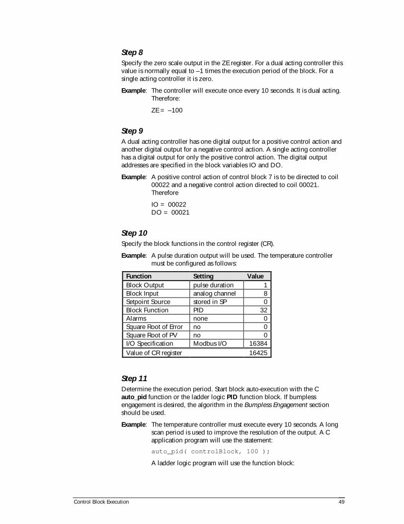
Control Block Execution 49
Step 8 Specify the zero scale output in the ZE register. For a dual acting controller thisvalue is normally equal to –1 times the execution period of the block. For asingle acting controller it is zero.
Example: The controller will execute once every 10 seconds. It is dual acting.Therefore:
ZE = –100
Step 9 A dual acting controller has one digital output for a positive control action andanother digital output for a negative control action. A single acting controllerhas a digital output for only the positive control action. The digital outputaddresses are specified in the block variables IO and DO.
Example: A positive control action of control block 7 is to be directed to coil00022 and a negative control action directed to coil 00021.Therefore
IO = 00022DO = 00021
Step 10 Specify the block functions in the control register (CR).
Example: A pulse duration output will be used. The temperature controllermust be configured as follows:
Function Setting Value Block Output pulse duration 1 Block Input analog channel 8 Setpoint Source stored in SP 0 Block Function PID 32 Alarms none 0 Square Root of Error no 0 Square Root of PV no 0 I/O Specification Modbus I/O 16384 Value of CR register 16425
Step 11 Determine the execution period. Start block auto-execution with the Cauto_pid function or the ladder logic PID function block. If bumplessengagement is desired, the algorithm in the Bumpless Engagement sectionshould be used.
Example: The temperature controller must execute every 10 seconds. A longscan period is used to improve the resolution of the output. A Capplication program will use the statement:
auto_pid( controlBlock, 100 );
A ladder logic program will use the function block:

Control Block Execution 50
controlBlock
PID100
Configuring Ratio/Bias Controllers The following block variables must be specified for an ratio/bias controller.Refer to the Control Block Variables section for a full description of thevariables.
Variable Description CR block control register FS full scale output (high limit) GA gain IB block input bias IO increase output address IP block input source OB block output bias ZE zero scale output (low limit)
Use the following steps to specify these block variables:
Step 1 Determine the source of the process value and store it in the IP register. Thesource is commonly the block output of another control block.
Example: The output of control block 6 controls the fuel flow to a combustionprocess. Control block 7 controls the air flow (open loop) to thesame process, using a ratio controller. Therefore, the input of block7 is
IP = 6
Step 2 Specify the block ratio in the gain register. Note that the gain is stored as a twodecimal place, fixed point number, so GA = ratio x 100.
Example: The output to the air damper must be 8.2 times the output to thefuel valve. Therefore
GA = 8.2 x 100 = 820

Control Block Execution 51
Step 3 Specify the output and input biases if required. These block variable areoptional. If no biases are required, they should be set to zero.
Example: An output bias of 230 is required for the air control. Also to zero theinput signal a 12 bit number of 109 is required to be subtracted fromthe process value ( input bias ). Therefore
OB = 230IB = 109
Step 4 Specify the full and zero scale outputs according to the process restrictions.
Example: The air flow controller must never open more than 90 percent orless than 10 percent to ensure proper operation. Therefore
FS = 32767 x 0.90 = 29490ZE = 32767 x 0.10 = 3276
Step 5 A ratio/bias controller may have an analog output or a time proportionedoutput. Specify the analog output register in the IO register. Specify the timeproportioned outputs in the IO and DO registers.
Example: The air valve position is determined by the analog output at holdingregister 40022. There is no decrease element since this is an analogoutput. DO need not be specified. Therefore
IO = 40022
Step 6 Specify the block functions in the control register (CR).
Example: An analog output will be used. The air flow controller must beconfigured as follows:
Function Setting Value Block Output analog 2 Block Input output of block IP 4 Setpoint Source not used 0 Block Function ratio/bias 64 Alarms none 0 Square Root of Error no 0 Square Root of PV no 0 I/O Specification Modbus I/O 16384 Value of CR register 16454
Configuring Cascade Controllers All P, PI, PD, PID and ratio/bias controllers may have their outputs cascaded tothe setpoint of another controller. One of the controllers is called the PrimaryController. It's output is an internal output which is sent to the setpoint of the

Control Block Execution 52
Secondary Controller. The output of the secondary controller can be analog,time proportioned (pulse duration or motor pulse duration) or internal (ifadditional cascading or simulation is being done).
PID and ratio/bias controller outputs may be cascaded indefinitely. In otherwords controller X may cascade into controller Y which may cascade intocontroller Z, and so on.
Configuring the Primary Controller This controller is configured the same as a single controller (refer to theprevious sections) with one exception - the controller output is internal. Thus,in the previous sections, the following steps have to be changed:
Control Register Step The control register, must be programmed to define the output as internal.Therefore the only bits which change are as follows:
Function Setting Value Block Output none 0
Output Channel Step The output channel does not need to be defined.
Configuring the Secondary Controller This controller is configured the same as a single controller (refer to theprevious sections) with one exception - the controller setpoint is cascaded fromthe primary controller's output. The only differences to the previous exampleare as follows:
Setpoint Step The setpoint need not be defined.
The source of the cascaded setpoint must be stored in register CA. It is theblock number of the primary controller.
Control Register Step The control register, must be programmed to define the setpoint source ascascaded from the primary control block output. Therefore the only bits whichchange are as follows:
Function Setting Value Setpoint Source from block CA 16
Example: The output of controller 15 is to be cascaded to the setpoint of
controller 20. The setpoint must be restricted to the range 6553 to32767, as the process value is a 4-20 mA value.
First, define the two controllers as discussed previously. The primarycontroller should have an internal output.

Control Block Execution 53
Second, set the high and low output limits in the primary controller.This will ensure that the setpoint in the secondary controller doesnot fall outside of the 4-20 mA range. Thus,
ZE15 = 6553FS15 = 32767
Third, define the setpoint source in the secondary controller (i.e. thesource is the primary controller). Thus,
CA20 = 15
Fourth, enable cascade setpoint by turning on the cascade bit in thecontrol register of the secondary controller. Thus,
CR20 = function_values + 16
Finally, engage both controllers. For our example assume that bothcontrollers will be activated with execution time of three seconds.
Configuring Automatic Alarms The following block variables must be specified for an automatic alarms. Referto the Control Block Variables section for a full description of the variables.
Variable Description AO alarm output address CR block control register HI high alarm level IP block input source LO low alarm level
The above variables can be used in conjunction with any of the other controlblock functions, or can be used in a control block whose sole function is alarmtesting.
Use the following procedure to configure automatic alarms:
Step 1 Determine the source of the process value and store it in the IP register. Aswith the PID and ratio/bias controllers a source needs to be declared as ananalog channel, a constant, or the output of another control block. This lastoption is useful in monitoring the output of a PID or ratio controller.
Example: Control block 7 will monitor analog input 30004. Therefore
IP7 = 30004
Step 2 Determine the block high and low alarm values in 12-bit quantities and assignto the high alarm (HI) and low alarm (LO) registers.
Example: An alarm is to occur if the block process value is higher than 82percent of full scale or lower than 32 percent of full scale. Therefore:
HI7 = 32767 x 0.82 = 26868LO7 = 32767 x 0.32 = 10485

Control Block Execution 54
Step 3 Determine the alarm output address and store it in the AO register.
Example: The alarm is to be output at coil 00019. Therefore the alarm addressis assigned as
AO7 = 00019
Step 4 Specify the block functions in the control register (CR).
Example: The control block has automatic alarms and an analog input source.The control block must be configured as follows:
Function Setting Value Block Output none 0 Block Input analog 8 Setpoint Source not used 0 Block Function alarms only 0 Alarms enabled 128 Square Root of Error no 0 Square Root of PV no 0 I/O Specification Modbus I/O 16384 Value of CR register 16520
Step 5 Determine the execution period. Start block auto-execution with the Cauto_pid function or the ladder logic PID function block.
Example: The automatic alarms are to be tested every 10 seconds. A Capplication program will use the statement:
auto_pid( controlBlock, 100 );
A ladder logic program will use the function block:
Disabling Automatic Alarms Sometimes automatic alarms in a PID or ratio/bias control block need to bedisabled. To disable the alarms, clear the alarm enable bit (bit 7) in the controlregister. In a C application program use this routine: void disableAlarms( unsigned controlBlock ) { unsigned controlRegister; controlRegister = get_pid( CR, controlBlock ); controlRegister &= 0xFF7F;
controlBlock
PID100

Control Block Execution 55
set_pid( CR, controlBlock, controlRegister ); } In a ladder logic program, it is easiest to assign a new value to the controlregister that does not enabled the automatic alarms.
Setting the execution period to zero also prevents automatic alarm scanning,but has the added effect of shutting off any PID or ratio/bias controller in thesame block. For alarm only blocks, setting the execution period to zero is theeasiest way to disable alarms.

Configuration Examples 56
Configuration Examples
This section illustrates practical configurations of the TelePACE PID controlblocks. Specific examples are given for the most common configurations. Morecomplicated applications are combinations of these common, simpleconfigurations.
Where applicable, a diagram is provided with the example to illustrate theconfiguration of a control block for the function described. The diagrams aresimilar to Figure 8. It shows the most general configuration of a control block,with all possible process inputs and outputs.
CONTROL BLOCK
P, PI, PD, PID or Ratio/BiasOptional Alarms
InputAnalog
Block Output
Constant
Output
Analog
Pulse Duration
Internal
Motor Pulse
Alarms
Setpoint
Cascade fromBlock Output Constant
Inhibit Execution
Figure 8: Control Block with All Inputs and Outputs
The solutions given in the examples describe the configuration in a generalformat. Refer to the Application Program Access section for details onimplementing the solutions in the C and Ladder Logic languages.

Configuration Examples 57
Alarms: High Alarm
High Temperature In A Dryer Waste sawdust is used as a fuel for a boiler to provide the steam requirementsof a sawmill. The moisture content of the sawdust must be lowered from 23%to 18% for efficient combustion. The sawdust is dried in a rotary dryer beforepassing onto the burners.
It is desired that the temperature in the rotary dryer not exceed 290 °C toprevent the burning of the sawdust and damage to the dryer. A thermocouplehas been installed to measure the dryer off-gas temperature and is read onanalog input 30004. A temperature of 290 °C corresponds to an unscaled 16bit precision number of 24720. The alarm must be checked every 2 seconds.
How would a block controller on the controller be configured to ring an alarmthat has been connected to digital output at coil 00029 when the temperatureexceeds 290 °C?
Solution The following information was extracted from the example:
• The 16 bit high alarm level is 24720.
• The input is read from analog input 30004.
• The alarm will be rung on coil 00029.
The control register must be configured as follows:
Function Setting Value Block Output none 0 Block Input analog input 8 Setpoint Source not used 0 Block Function alarms only 0 Alarms enabled 128 Square Root of Error no 0 Square Root of PV no 0 I/O Specification Modbus I/O 16384 Value of CR register 16520
The following entries will configure a control block to detect and trigger thehigh alarm. See Figure 9 for a block diagram of the controller.
Variable Value Comment IP 30004 Input from analog input 30004 HI 24720 290 °C corresponds to 24720 AO 00029 Alarm bell is attached to coil 00029 CR 16520 See table above period 20 Execute every 2 seconds

Configuration Examples 58
Alarms: High and Low Alarms
Low and High Temperature in a Dryer In the system of the previous example, the dried sawdust must not be below200 °C before entering the burners for the steam boiler. A temperature of 200°C corresponds to an unscaled 16 bit precision number of 16080. The samealarm bell can be used for either high or low alarms. How would the blockcontroller be configured to ring the alarm when the temperature is under 200°C?
Solution The following additional information was extracted from the example:
• The 16 bit low alarm level is 16080.
• The same high alarm level and control register configuration is used.
The configuration is identical to the previous example except for the additionof the low alarm setpoint. The following entries will configure a control blockto detect and trigger the high alarm. See Figure 9 for a block diagram of thecontroller.
Variable Value Comment IP 30004 Input from analog input 30004 HI 24720 290 °C corresponds to 24720 LO 16080 200 °C corresponds to 16080 AO 00029 Alarm bell is attached to coil 00029 CR 16520 See table above period 20 Execute every 2 seconds
CONTROL BLOCK
Alarms OnlyInput
Analog
Block Output
Constant
Alarms
Figure 9: Alarm Testing Block Inputs and Outputs
PID Control: Analog Output
Temperature Control on a Heated Tank Sulfuric acid is electrically heated in a continuous flow stirred tank beforebeing used to leach a copper, nickel and iron bearing ore concentrate. Theheater is supplied current as determined from the output of holding register40018. The acid flow fluctuates since it is taken from the recycle of a semi-batch process.
Due to these fluctuations, a PID controller is required to maintain thetemperature at a setpoint of 90 °C (corresponding to an unsigned number28536, read on analog input 30004). It is only necessary to execute controlonce every 10 seconds. An open-loop response experiment yielded thesetuning parameters:

Configuration Examples 59
• GAIN = 11.2 (dimensionless gain)
• RESET TIME = 47 seconds
• DERIVATIVE TIME = 109 seconds
How would a block controller be configured to perform this function?
Solution The following information was extracted from the example:
• The 16 bit setpoint is 28536.
• The gain is 11.2.
• The reset time is 470 tenths of a second.
• The derivative time is 1090 tenths of a second.
• The input is analog input register 30004.
• The output is holding register 40018.
The control register must be configured as follows:
Function Setting Value Block Output analog channel 2 Block Input analog channel 8 Setpoint Source stored in SP 0 Block Function PID 32 Alarms none 0 Square Root of Error no 0 Square Root of PV no 0 I/O Specification Modbus I/O 16384 Value of CR register 16426
The following entries will configure a control block to perform the requiredcontrol. See Figure 10 for a block diagram of the PID controller.
Variable Value Comment SP 28536 corresponds to the 90 °C setpoint IP 30004 read temperature from 30004 GA 1120 open loop response value x 100 RE 470 open loop response value x 10 RA 1090 open loop response value x 10 IO 40018 output to heater on 40018 CR 16426 see table above FS 32767 allow full range of output values
(0..32767) ZE 0 allow full range of output values
(0..32767) period 100 execute every 10 seconds

Configuration Examples 60
CONTROL BLOCK
P, PI, PD, PIDInput
Analog
Block Output
Constant
Output
Analog
Pulse Duration
Internal
Motor Pulse
Setpoint
Cascade fromBlock Output Constant
Figure 10: General Block Diagram for PID Control
PID Control: Analog Output and Alarms
Temperature Control on a Heated Tank The sulfuric acid used in the process described in the previous example boils ata temperature of 103 °C. Also, the leaching rate for iron is negligible if the acidis below 75 °C.
How would the block controller be configured to detect temperatures below75 °C (read as 27416 on analog input 30004) and above 103 °C (read as29608 on 30004), ring an alarm bell connected to coil 00025, as well asperform PID control?
Solution The following additional information was extracted from the example.
• The setpoint and tuning parameters are the same as for the previousexample.
• The 16 bit high alarm level is 29608.
• The 16 bit low alarm level is 27416.
• The alarm output is directed to coil register 00025.
The control register must be configured as follows:
Function Setting Value Block Output analog channel 2 Block Input analog channel 8 Setpoint Source stored in SP 0 Block Function PID 32 Alarms enabled 128 Square Root of Error no 0 Square Root of PV no 0 I/O Specification Modbus I/O 16384 Value of CR register 16554
The following entries will configure a control block to perform the requiredcontrol. See Figure 10 for a block diagram of the PID controller.
Variable Value Comment SP 28536 corresponds to the 90 °C setpoint IP 30004 read temperature from register 30004

Configuration Examples 61
GA 1120 open loop response value x 100 RE 470 open loop response value x 10 RA 1090 open loop response value x 10 IO 40018 output to heater on 40018 CR 16554 see table above FS 32767 allow full range of output values
(0..32767) ZE 0 allow full range of output values
(0..32767) HI 29608 corresponds to 103 °C high alarm LO 27416 corresponds to 75 °C low alarm AO 00025 coil 00025 period 100 execute every 10 seconds
PID Control: Single Acting Time Proportioned Output
pH Control On a Continuous Stirred Tank Reactor A reaction is taking place in a Continuous Stirred Tank Reactor (CSTR) thatconsumes acid. It was determined that the optimum pH for the reaction is 3.2.The output from a pH meter is read on analog input 30008 and a pH readingof 3.2 corresponds to the 16-bit precision number 10328.
The acid is fed to the process by a fixed speed pump, that can be turned on oroff by a digital output at coil 00026. An open-loop response experimentyielded these tuning parameters:
• GAIN = –1.2 (dimensionless gain)
• RESET TIME = 122 seconds
• DERIVATIVE TIME = 39 seconds
How would a block controller be configured to perform PID control with pulseduration output?
Solution This is an example of single acting control. If the pH is above the setpoint thenacid is added. Also, note that the dimensionless gain is negative. This indicatesthat a positive control action is required when a negative error occurs. Anegative gain is used when negative control action is required for a positiveerror. (The negative gain is also predicted by the open-loop tuning technique.)
The following information was extracted from the example:
• The 16 bit setpoint is 10328.
• The gain is –1.2.
• The reset time is 1220 tenths of a second.
• The derivative time is 390 tenths of a second.
• The input is taken from analog input 30004.
• Output is directed to coil 00026.

Configuration Examples 62
• The full scale output 200 tenths of a second (equal to sampling period).
• The zero scale output is 0.
The control register must be configured as follows:
Function Setting Value Block Output pulse duration 1 Block Input analog channel 8 Setpoint Source stored in SP 0 Block Function PID 32 Alarms none 0 Square Root of Error no 0 Square Root of PV no 0 I/O Specification Modbus I/O 16384 Value of CR register 16425
The following entries will configure a control block to perform the requiredcontrol. See Figure 10 for a block diagram of the PID controller.
Variable Value Comment SP 10328 corresponds to pH of 3.2 IP 30004 read pH from analog input 30004 GA –120 open loop response value x 100 RE 1220 open loop response value x 10 RA 390 open loop response value x 10 ZE 0 no negative output for single acting
control FS 200 maximum on time is equal to execution
period IO 00026 coil 00026 CR 16425 see table above period 200 execute every 20 seconds
PID Control: Dual Acting Time Proportioned Output
pH Control on a Continuous Stirred Tank Reactor In the system of the previous example, it was decided to add caustic soda (astrong base) if the pH was below setpoint. Since a strong acid was used, apump to deliver the caustic was chosen that had the same pumping capacity asthe acid pump.
The caustic pump can be turned on with digital output at coil 00027. Howcould the block controller be re-configured for this dual-acting control?
Solution The following information was extracted from the example:
• The setpoint, tuning parameters and control register configuration are thesame as in the previous example.

Configuration Examples 63
• Since the pulse duration output has a negative as well as a positive controlaction, the zero scale output must be set equal to the negative value of theexecution period in tenths of a second (i.e. –200 tenths).
• The decrease digital output is coil 00027.
• A deadband must be used to prevent the conflicting action of the outputs asthe process error approaches zero. This is arbitrarily assigned a value of 10.
The following entries will configure a control block to perform the requiredcontrol.
Variable Value Comment SP 10328 corresponds to pH of 3.2 IP 30004 read pH from analog input 30004 GA –120 open loop response value x 100 RE 1220 open loop response value x 10 RA 390 open loop response value x 10 ZE –200 maximum decrease output on-time equal
to execution period FS 200 maximum increase output on-time equal
to execution period IO 00026 coil 00026 DO 00027 coil 00027 CR 16425 see table in previous example DB 10 deadband prevents addition of both acid
and base period 200 execute every 20 seconds
PID Control: Cascade Controllers
Furnace Temperature Control A furnace (soaking pit) is used to heat cold steel slabs to 1050 °C before beinghot rolled to strip steel. Off gases (methane and other hydrocarbons) from cokeovens are used to heat the furnace. A flow meter monitors the gas flow rate andthe output of this meter is monitored on analog input 30002.
The flow can be continuously adjusted with a valve whose position isdetermined by the output of holding register 40021. A closed-loop tuningexperiment (using the Ziegler-Nichol method) produced the following tuningconstants for a PID flow controller:
• GAIN = 201 (dimensionless gain)
• RESET = 2.1 (seconds)
• DERIVATIVE = 4.6 (seconds)
The temperature of the furnace is to be controlled by manipulating the setpointof the fuel-gas flow controller (cascade control). A thermocouple has beeninstalled inside the furnace and the temperature is monitored on analog input30001.

Configuration Examples 64
A temperature of 1050 °C corresponds to an unscaled number of 18440. Anopen-loop experiment produced the following constants for the PIDtemperature controller:
• GAIN = 19.2 (dimensionless gain)
• RESET = 490 (seconds)
• DERIVATIVE = 620 (seconds)
How would a block controller be configured to implement cascade control ofthe furnace temperature?
Solution Two control blocks are required to implement the temperature control: one tocontrol the flow rate of the fuel-gas, the other to control the temperature bymanipulating the setpoint of the flow controller. The following information wasextracted from the example for the fuel-gas flow controller:
• The gain is 201.
• The reset time is 21 tenths of a second.
• The derivative time is 46 tenths of a second.
• The input is taken from analog channel 30002.
• Output is directed to analog output 40021.
• The setpoint is taken from the output of the temperature controller.
The control register must be configured as follows:
Function Setting Value Block Output analog channel 2 Block Input analog channel 8 Setpoint Source from block CA 16 Block Function PID 32 Alarms none 0 Square Root of Error no 0 Square Root of PV no 0 I/O Specification Modbus I/O 16384 Value of CR register 16442
The following entries will configure the fuel gas flow controller using block 0.See Figure 11 for a block diagram of the cascaded PID controllers.
Variable Value Comment CA0 7 setpoint comes from block 7 IP0 30002 read gas flow from 30002 GA0 20100 closed loop response value x 100 RE0 21 closed loop response value x 10 RA0 46 closed loop response value x 10 IO0 40021 output to flow value actuator analog
output 40021 CR0 16442 see table above FS0 32767 allow maximum range of output

Configuration Examples 65
(0..32767) ZE0 0 allow maximum range of output
(0..32767) period 200 execute every 20 seconds
The following information was extracted from the example for the temperaturecontroller:
• The 16 bit setpoint is 18440.
• The gain is 19.2.
• The reset time is 4900 tenths of a second.
• The derivative time is 6200 tenths of a second.
The control register must be configured as follows:
Function Setting Value Block Output none 0 Block Input analog channel 8 Setpoint Source stored in SP 0 Block Function PID 32 Alarms none 0 Square Root of Error no 0 Square Root of PV no 0 I/O Specification Modbus I/O 16384 Value of CR register 16424
The following entries will configure the temperature controller using block 7.
Variable Value Comment SP7 18440 corresponds to 1050 °C setpoint IP7 30001 read temperature from 30001 GA7 1920 closed loop response value x 100 RE7 4900 closed loop response value x 10 RA7 6200 closed loop response value x 10 CR7 16424 see table above FS7 32767 upper limit of setpoint for block 0 ZE7 0 lower limit of setpoint for block 0 period 200 execute every 20 seconds

Configuration Examples 66
PRIMARYCONTROL BLOCK
P, PI, PD, PID or Ratio/Bias
InputAnalog
Block Output
Constant
Output
Setpoint
Cascade fromBlock OutputConstant
SECONDARYCONTROL BLOCK
P, PI, PD, PID or Ratio/Bias
InputAnalog
Block Output
Constant
Output
Analog
Pulse Duration
Internal
Motor Pulse
Setpoint
Cascade fromBlock Output
Analog
Pulse Duration
Internal
Motor Pulse
Optional outputs(not normally used)
Figure 11: Cascade Control Block Diagram
PID Control: Square Root Linearization for Flow Control
Liquid Flow Control Water is flowing through a pipe from a constant pressure source to a dilutiontank. The flow is manipulated by a linear control valve whose position can beadjusted by analog output 40018. A U-tube manometer filled with mercurymeasures the pressure (and hence, the flow-rate) of the water as indicated bythe height of the mercury.
The height of the mercury is continuously monitored by analog input 30002. Aflow of 14 USGPM is desired and is read on analog input 30002 as a unscalednumber of 1089. A minimum flow that corresponds to a 16 bit number 776 onthe analog output is also required. A closed-loop response experimentprovided the following PID tuning constants:
• GAIN = .7 (dimensionless gain)
• RESET = 1.2 (seconds)
• RATE = 2.4 (seconds)
How would a block controller be configured to perform the flow control?
Solution From the Bernouille equation, the flow of water through a pipe is proportionalto the square root of the pressure difference or the head height (measured bythe manometer). To obtain the flow reading from the manometer height readfrom analog input 30002, the square root must be taken of the process value.
The following information was extracted from the example:
• The 16 bit setpoint is 33 * 128 (the normalized square root of 1089)
• The gain is 0.7.
• The reset time is 12 tenths of a second.

Configuration Examples 67
• The derivative time is 24 tenths of a second.
• The input is read from analog input 30002.
• The controller output is directed to 40018.
• The 16 bit full scale output is 32767.
• The 16 bit zero scale output is 776.
The control register must be configured as follows:
Function Setting Value Block Output analog channel 2 Block Input analog channel 8 Setpoint Source stored in SP 0 Block Function PID 32 Alarms none 0 Square Root of Error no 0 Square Root of PV yes 512 I/O Specification Modbus I/O 16384 Value of CR register 16938
The following entries will configure a control block to perform the requiredcontrol.
Variable Value Comment SP 4224 corresponds to normalized square root of
1089 IP 30002 read manometer input from analog input
30002 GA 70 closed loop response value x 100 RE 12 closed loop response value x 10 RA 24 closed loop response value x 10 IO 40018 output to valve actuator on analog output
40018 CR 16938 see table above FS 32767 allow output to reach maximum value ZE 776 limit minimum value of output period 10 execute every second
Output Tracking
Combustion Air Control The flow of combustion air to the furnace of the cascade control example isalso controlled. The required air flow is 3 times the flow of the fuel-gas. Alinear valve controls the flow of the air. The valve position is determined by theoutput of analog output 40021.
How would a block controller be configured to control the air flow?
Solution The following information was extracted from the example.

Configuration Examples 68
• The control block in the cascade control example does not need to bereconfigured.
• The gain of the air flow controller is 3.
• The output of the controller is directed to analog output 40021.
• The controller input comes from the fuel-gas control block output (block 7).
The control register must be configured as follows:
Function Setting Value Block Output analog channel 2 Block Input from block IP 4 Setpoint Source not used 0 Block Function ratio/bias 64 Alarms none 0 Square Root of Error no 0 Square Root of PV no 0 I/O Specification Modbus I/O 16384 Value of CR register 16454
The following entries will configure a control block 8 to perform the requiredcontrol.
Variable Value Comment GA8 300 ratio x 100 IP8 7 block input comes from block 7 CR 16454 see table above IO 40021 output to control valve actuator on
analog output 40021 FS 3120 limit maximum output to valve actuator ZE 1200 limit minimum output to valve actuator period 20 execute every 2 seconds
Ratio Control
Reagent Additions to a Continuous Stirred Tank Reactor Waste water is flowing into a Continuous Stirred Tank Reactor (CSTR) wherealum is added. The amount of alum added is proportional to the flow of waterthrough the reactor. A flow meter is read on analog input 30005. Output to thealum metering is via analog output 40022. A ratio of 7.2 is required.
How would a block controller be configured to control the alum addition?
Solution The following information was extracted from the example:
• The input is taken from analog input 30005.
• The output is directed to analog output 40022.
• The ratio gain is 7.2.
• No output bias is required.

Configuration Examples 69
The control register must be configured as follows:
Function Setting ValueBlock Output analog channel 2Block Input analog channel 8Setpoint Source not used 0Block Function ratio/bias 64Alarms none 0Square Root of Error no 0Square Root of PV no 0I/O Specification Modbus I/O 16384Value of CR register 16458
The following entries will configure a control block to perform the ratio/biascontrol.
Variable Value CommentGA 720 ratio x 100IP 30005 read flow on analog input 30005CR 16458 see table aboveIO 40022 output to metering pump on analog
output 40022FS 32767 allow maximum range of outputZE 0 allow maximum range of outputperiod 10 execute every second
CONTROL BLOCK
Ratio/BiasInput
Analog
Block Output
Constant
Output
Analog
Pulse Duration
Internal
Motor Pulse
Figure 12: Ratio/Bias Control Block Diagram
Batch ControlThe following example illustrates how seven control blocks can be used tocontrol a batch process.
Figure 13 shows the batch system. Three liquid reagents (A, B and C) are addedin a fixed ratio to the main stream. The flow rate of the main stream ismeasured and controlled by a PID controller.
The output of this controller is fed to three ratio controllers. The output of eachratio controller is the setpoint of a PID control block for each of the reagents.The flow rate is controlled by the PID algorithm.
A high alarm for an output of zero automatically turns off the pump if theoutput of the controller is zero, preventing overheating (this irregular use of analarm output illustrates that control blocks are limited only by the imagination).
Such a configuration facilitates the changing of the batch recipe. If the recipechanges for the batch process, then each ratio controller gain can be adjustedin proportion.

Configuration Examples 70
Adjustments to increase the flow through-put of the batch are accomplished bythe single adjustment of the setpoint of the main flow control block. Theadditional demand for the reagents is automatically handled by the ratiocontrollers.
P, PI, PID orPID
Controller
RatioController
Flow
Output
Alarm
Stream C
P, PI, PID orPID
Controller
RatioController
Flow
Output
Flow SetpointVolumetric Flow Measurement
Alarm
Stream B
P, PI, PID orPID
Controller
RatioController
Flow
Output
Alarm
Stream A
P, PI, PID orPID
Controller
Main Product Stream
Figure 13: Batch Process Schematic

Tuning PID Controllers 71
Tuning PID Control Blocks
PID controllers must be tuned before they can be used. This process consists ofdetermining the parameters K, T and R, known collectively as tuningparameters. These parameters vary from depending upon the process, thesensors used, and the control element. In this section methods will be outlinedto obtain these parameters.
Tuning techniques may be categorized into two classes: open loop tuning andclosed loop tuning. In open loop tuning, the response of the process value to astep change in the control element's output is used to obtain the proportionalgain, the reset time and the rate gain. The PID controller is not coupled to theprocess.
In closed loop tuning, the response of the process coupled to the PIDcontroller is used to determine the parameters. Each method has its advantages.The Ziegler-Nichol technique will be discussed as a closed loop method andthe Cohen-Coon technique will be discussed as an open loop technique.
It is recommended that this section be read and understood thoroughly, even ifthe reader is familiar with these techniques, as the SCADAPack and TeleSAFEcontrollers use dimensionless proportional gain to speed the execution of thealgorithm.
Closed Loop Tuning: The Ziegler-Nichol MethodThe Ziegler-Nichol tuning method is used for processes with quick responseand little dynamic lag (i.e. the process value responds quickly to a change inthe control element). Processes with lag times of less than 30 seconds can betuned using this method. The parameters derived are be to used only as initialestimates. Further fine tuning is required to achieve the optimum controlsettings.
The technique is:
1. Close the control loop with the a PID control block:
• Select a control block.
• Specify the analog channel from which the process value will beread.
• Specify ZE as 0 and FS as 32767.
• Specify the output channel. The control element should be on thischannel.
• Arbitrarily assign a setpoint. This setpoint is dimensionless and mustbe within the range of 0 to 32767. The setpoint must not exceed thesafe operational limits of the process.
• Set the control register to an appropriate configuration.
• Set the sampling period to 1 second.

Tuning PID Controllers 72
2. The process response must be recorded. A data acquisition program mustbe written to record the time and the process value. Run the dataacquisition program.
3. Slowly increase the gain of the PID controller until a steady stateoscillation is detected in the process value. It may be necessary to make achange in the setpoint to start the oscillation (a change of +/– 1000 isadequate).
4. Record the gain Ku when a steady state oscillation has been achieved. Theexperiment is over and the controller may be turned off.
5. Plot the process response for the gain that caused the steady state error.(The response was recorded by the data acquisition program.)
6. Determine the period of oscillation Pu from the response as shown inFigure 14.
7. Determine the P, PI or PID parameters from the values of Ku and Pu usingthe table below.
Controller K T RProportional 0.5 x Ku
Proportional-Integral 0.45 x Ku Pu/1.2Proportional-Integral-Derivative 0.6 x Ku Pu/2 Pu/8
Once the required parameters have been found, configure the controller asdescribed in previous sections of the manual, and start the controller executing.The controller is now operating in real time and can be tested for response andfine tuned as required.
time
setpoint
processvalue
ProcessValueResponse
Increasing Proportional Gain
Pu
K=Ku K>KuK<Ku
Figure 14: Ziegler-Nichol Response Characteristics
Open Loop Tuning: The Cohen-Coon MethodThe Cohen-Coon technique is simplistic when compared to the closed loopmethod. It is best used when a response time of greater than 30 seconds existsin the process. It should not be used for response times less than 30 seconds.As with the Ziegler-Nichol method, this method yields only rough estimates ofthe PID parameters and fine tuning may be necessary.
The technique is:
1. Run the data acquisition program.
2. Set the output of the control element at an arbitrary dimensionless numberin the range of 0 to 32767. Record this number.
3. Wait for the process to reach steady state.

Tuning PID Controllers 73
4. Introduce a step increase in the output to the control element. Record thisnew output and the time of the step increase.
5. Wait for the process to reach steady state.
6. Plot the response. Plot the process value on the Y-axis and the elapsed time(in seconds) from the step increase, on the X-axis.
7. Obtain Td and Tr from the response curve as shown in Figure 15 below.
8. Calculate Kp = Bu/M where M is the magnitude of the step change.
9. Calculate the PID tuning parameters from Kp, Td and Tr using the tablebelow.
Controller K T RProportional T
K TTT
r
p d
d
r×+
�
��
�
��1
3
Proportional-Integral
TK T
TT
r
p d
d
r×+
�
��
�
��0 9
12. T
TT
TT
dd
r
d
r
× +�
��
�
��
+
303
920
Proportional-Integral-Derivative
TK T
TT
r
p d
d
r×+
�
��
�
��
43 4
TTT
TT
dd
r
d
r
× +�
��
�
��
+
326
138
4
1 12
TT
T
r
d
r
+
Once the required parameters have been found, configure the controller asdescribed in previous sections of the manual, and start the controller executing.The controller is now operating in real time and can be tested for response andfine tuned as required.
time
Bu
Td+TrTd0
0
processvalue
ProcessValueResponse
point ofinflection
slope = Bu/Tr
Figure 15: Cohen-Coon Response Characteristics
Fine TuningAfter testing the response of the PID controller, it may be necessary to finetune. The table below lists symptoms of a poor response and recommendedremedies.
Problem Recommended RemedyOvershoot of setpoint is toolarge
Decrease gain
Response is too slow Increase gain and/or decreasereset time. Increasing rate gain

Tuning PID Controllers 74
may help.Response is oscillatory Decrease gain and/or increase
reset time. Decreasing the scantime may help.
Steady state offset Decrease reset time.Response starts fast but slowto reach setpoint
Decrease reset time.
Selecting the Execution PeriodThe execution period is the interval at which a control block executes. Theselection of a proper execution period is important. Improper selection canresult in unstable control. The method of selection is different depending uponwhether an analog output or time proportioned output is used by the controlblock. The sections below describe qualitative criteria for choosing the period.
The Jury Stability Test is a quantitative method of determining an adequateexecution period, but the details of this mathematical approach are left to thereferences. In most cases, the selection of a period can be judgmental, as longas the principles described below are followed.
PID or Ratio/Bias ControllersExecution periods should be as short as possible while avoiding unnecessaryslowing of any application programs that may be running in the foreground.Long periods should be avoided since these can cause unstable control. As arule of thumb for PID control, the period should be less than the reset time.
Time Proportioned Output ControllersExecution periods should be as long as possible to improve the resolution ofthe pulse output. Also, if pumps are being controlled by the digital output, theinfrequent starts will decrease wear. Once again, excessively long periodscould result in unstable control.

Advanced Control 75
Advanced Control
Control schemes on the controller are not limited to those provided in thecontrol blocks. The C and Ladder Logic languages contain all of the I/Ostatements required to program sophisticated control algorithms for regulatingprocesses that are uncontrollable using PID or ratio/bias controllers. The I/Ostatements are easily learned. Refer to the C Tools or Ladder Logic user manualfor explanations of the I/O commands.
This section outlines how advanced algorithms may be programmed. Aworking knowledge of the application language is assumed, as well as athorough knowledge of modern control theory. Readers unfamiliar withmodern digital control theory are recommended to read "Digital ControlSystems" by Kuo. This book is an excellent source of information upon how toapproach control problems using the digital computer.
The major underpinning of an advanced algorithm is that a thoroughknowledge of the process is required. This means reliable models must existupon which the output of the controller is based. The main driving force forusing such algorithms is that response times are much shorter than PIDcontrollers and overshoot is practically nil.
The Digital Computer and Discrete ControlThe use of advanced control algorithms would be impossible without thedigital computer. Such algorithms are characterized by multiple linearcalculations which can only be handled by a computer in a reasonable amountof time needed for process control.
Since the digital computer is a discrete controller, Z-transforms are required forthe transfer functions of the system to be controlled. In illustrating the use of anadvanced algorithm, it is assumed that the Z-transform has been derived. Oncethe Z-transform has been found, the programming of the algorithm is relativelysimple.
Programming AlgorithmsThis discussion involves the implementation of an advanced algorithm. It isassumed that the algorithm is executed at a regular time interval.
1. Write output equation in terms of inputs and previously saved values.
2. Output the calculated value.
3. Save the necessary values for the next output and return from thesubroutine.
4. Call the subroutine from within the main program at a regular interval. Thesettimer() and timer() functions can be used to measure a specific timeinterval.

Advanced Control 76
Programming NoteThe control block whose number is the same as the timer number cannot beused as a time proportioned output controller. The timer is used when a timeproportioned output is selected. In the example below, block 4 cannot have atime proportioned output, as the timer is used in the program.
ExampleThis example implements a control algorithm in C. The output equation for asystem is
c dbase c c a= × + + × + × + ×39 30001 22 3 0 905 0 42 21 2 1. ( ) . . .
where: c is the present outputc1 is the last outputc2 is the second last outputa1 is the last input
The calculated value is output to register 40013. The control routine is calledby using a simple timing loop.#include <mriext.h>#include <iohw.h>
#define PERIOD 10#define DELAY_TIMER 4#define CONTROL_OUTPUT 40013#define PROCESS_INPUT 30001
void controlAlgorithm( void ){
static int output[3] = 0; /* output values */static int input[2] = 0; /* input values */
/* Read the current inputs */
input[0] = dbase( MODBUS, PROCESS_INPUT );
/* Calculate and write the next output */
output[0] = 3.9 * input[0] + 22.3 +0.905 * output[1] +0.42 * output[2] + 2.0 * input[1];
setdbase( MODBUS, CONTROL_OUTPUT, output[0] );
/* Save current values for next execution */
input[1] = input[0];output[2] = output[1];output[1] = output[0];
}
void main( void ){
/* Initialize the timer to count seconds */
interval( DELAY_TIMER, 10 );settimer( DELAY_TIMER, 0 );
/* Main loop */
while (TRUE){
/* Execute at specified interval */
if (timer( DELAY_TIMER ) == 0){
controlAlgorithm();settimer( DELAY_TIMER, PERIOD );

Advanced Control 77
}
/* The rest of the program */}
}

Transfer Function 78
Appendix A: Transfer Function
The equation for the PID algorithm in continuous form is:
m KeKT
e dt KRdpdt
mi
t
s= + + +�0
Equation A-1
Since the computer algorithm does not operate continuously, the discreteequivalents of the integral and derivative terms are taken:
m KeKTT
eKRT
p p mi ii
nn
i
i i s= + − − +=
−�0
1( ) Equation A-2
where: i denotes the current sampling timeT is the sampling period
Now consider the output of the previous sampling period as shown in equationA-3.
m KeKTT
eKRT
p p mi ii
nn
i
i i s− −=
−
− −= + − − +�1 10
1
1 2( )
Equation A-3
Taking the backwards difference of equations A-2 and A-3 we have:
m m K e eKTT
eKRT
p p pi i i ii
i i i i− = − + − − −− − − −1 1 1 22( ) ( )
m m K e eKTT
eKRT
p p pi i i ii
i i i i= + − + − − −− − − −1 1 1 22( ) ( )
Equation A-4
Taking the Z transform of equation A-4 yields:
M z z M z K E z z E z KTT
E z KRT
P z z P z z P zi
( ) ( ) ( ( ) ( )) ( ) ( ( ) ( ) ( ))= + − + − − +− − − −1 1 1 22
M z KE zKTE z
T zKRT
P z zi
( ) ( )( )
( )( )( )= +
−− −−
−
111
1
Equation A-5
Equation A-5 should be used in any analysis of the transfer function of asystem.