2012 cookie cupboards webinar - girl scouts
TRANSCRIPT
AEROMOTIVE Part # 17158
05’- Present Mustang Race Fuel System Kit INSTALLATION INSTRUCTIONS
CAUTION: Installation of this product requires detailed knowledge of automotive systems and
repair procedures. We recommend that this installation be carried out by a qualified automotive technician.
Installation of this product requires handling of gasoline. Ensure you are working in a well ventilated area with an approved fire extinguisher nearby. Extinguish all open flames, prohibit smoking and eliminate all sources of ignition in the area of the vehicle before proceeding with the installation.
When installing this product, wear eye goggles and other safety apparel as needed to protect yourself from debris and sprayed gasoline.
WARNING!
The fuel system is under pressure. Do not open the fuel system until the pressure has been relieved. Refer to the appropriate vehicle service manual for the procedure and precautions for relieving the fuel system pressure. Aeromotive system components are not legal for sale or use on emission controlled motor vehicles. This kit contains the following parts: 1 ea fuel filter bracket (12305) 1 ea fuel filter (12321) 1ea p/n 14141 Ford 5.4L DOHC Fuel Rails 1ea p/n 13128 EFI Regulator 1ea p/n 15115 Ford Adapter Fuel Pressure Senor 1ea p/n 15102 Supply Adapter Tee Fitting 6ea p/n 15607 AN-08 To Cutoff AN-08 Union 5 ea p/n 15610 AN-08 to cutoff AN-10 union 1ea p/n 15631 Fuel Sample Valve 2 ea p/n 15645 AN-08 tank fitting 9ea p/n 15653 –8 Straight Hose End 3ea p/n 15654 -8 45-degree Hose End
13ea p/n 15655 –8 90-Degree Hose End 3ea p/n 15663 -8 180-Degree Hose End 1ea p/n 15649 AN-06 Cutoff To AN-08 Union 1ea p/n 15674 Y-Block 8-2x8 4 ea p/n 15685 AN-08 bulkhead fitting 12 ea cushioned hose clamps 12 ea self-drilling screw 3ea p/n 17704 Triple AN-08 Hose Separator 1 ea fuel cell (18667) 1ea Vacuum Tee 50ft –8 Black Nylon Braided Fuel Line 3ft 5/32” Vacuum Line
Section 1 - Fuel system installation, Chassis: 1-1. Once the engine has been allowed to cool, disconnect the negative battery cable and relieve the fuel system pressure. 1-2. Raise the vehicle and support it with jack stands. 1-3. Referring to the appropriate vehicle service manual for instructions, drain, disconnect any electrical and fuel
component connections and remove the OEM fuel tank. The removal of the vehicles drive shaft and exhaust system may be necessary for fuel tank removal.
1-4. Once the OEM fuel tank has been removed, tie up all electrical connections and hoses that were disconnected. 1-5. Find a suitable place in the trunk to mount the fuel cell. For mounting use Aeromotive bracket P/N 18701, or call
Aeromotive. Pictured is a typical install of a fuel cell in a SN197, Figure 1-1.

Figure 1-1
1-6. Find a suitable place for the two tank vent pass through fittings (15645), typical locations is trunk floor. Drill two holes making sure you place them in a location where you can get access to the back side for the lock nuts. The system comes with two tanks vents and both must be used for the system to function properly.
1-7. Assembly two identical hoses, 90 degree hose end on one side and a straight on the other. These will be used for the
tank vent hoses, Figure 1-2.
Figure 1-2

1-8. Next find a place for the two AN-08 fuel bulk heads, p/n 15685. The most common place for the two bulk heads are on the driver’s side in the spare tire well. Drill the two holes two inches apart, Figure 1-3.
Figure 1-3
1-9. Install one of the supplied 15610 fittings into the outlet of fuel pump (Make sure the fitting has the AN-10 o-ring installed on it).
1-10. Assembly two hoses, both with 90-degree hose end on all ends. One will be used for the pump outlet and the other
will be used for the return, Figure 1-4.
Figure 1-4
1-11. After connecting the return and pump outlet lines to the bulk heads, move to the under side of the vehicle. 1-12. Find a location for the fuel filter (12321) and mounting bracket (12305). Typical mounting location on the passenger
side frame rail, Figure 1-5.

Figure 1-5 1-13. Once the filter has been mounted, assemble a hose with a 90-degree fitting on one end and a straight on the other.
This line will finish the connection from the feed bulk head to the filter, Figure 1-6. NOTE: Make sure you connect to the pump outlet and not the return.
Figure 1-6 1-14. In the engine bay find a suitable place for the two AN-08 bulk heads. Typical place for these are behind the
passenger side strut tower, Figure 1-7.

Figure 1-7
1-15. Once you have both bulk heads installed, assemble a hose with a 45-degree fitting on one end and a straight on the other. This line will connect to the outlet of the fuel filter (45-degree hose end) and one of the bulk heads you just installed.
1-16. Finish up the last line by assembling a hose with a straight hose end on one side and a 90-degree on the other.
This hose will make the connection from the return bulk head in the engine bay to the return bulk head in the trunk. 1-17. Now use the cushioned hose clamps to attach the lines to the body of the vehicle. Note: Be sure to route all fuel
lines clear of any moving suspension or drivetrain components and any exhaust components! Protect fuel lines from abrasion and road obstructions or debris.
1-18. For pump wiring, use Aeromotive part # 16301. Section 2 – Engine Fuel Install: The following steps are typical of most installations: 2-1. Remove the air intake ducting from the throttle body. 2-2. Note the location of and remove any vacuum lines connected to the air intake and position them out of the way. 2-3. Unplug the TPS sensor and drive-by wire connector, which is typically located on top of the throttle body. 2-4. Remove the throttle body by removing 4 screws. 2-5. Now remove the blower inlet tube by removing the 4 bolts. 2-6. Check for any dirt or debris around the fuel injectors. If any is evident, wash it off with some solvent parts cleaner or
wipe it off with a clean shop towel.

2-7. Disconnect the electrical connector at each injector, making note of the location of each. Also disconnect the fuel pressure sensor located on the passenger side fuel rail.
2-8. Disconnect the supply line from the OEM fuel rails. This line is attached by a special quick disconnect fitting which
does not require a special tool for removal. Place clean shop towels around the open fuel line to catch any gasoline that may drip out and to prevent any dirt from entering the fuel lines.
2-9. Remove the 4 bolts that attach the fuel rail to the lower intake. 2-10. Place clean shop towels around the injectors to catch any gasoline that may be spilled during their removal.
Remove the injectors from the manifold by gently pulling upward on the fuel rail / injector assembly. Keep all injectors connected to the fuel rails. If an injector does pull out of the fuel rail, it may spill a large amount of fuel.
2-11. Carefully remove the fuel injectors from the OEM fuel rail. 2-12. Remove the old o-rings from the fuel injectors, inspect the injectors for any dirt or debris and clean if needed. It is
suggested that the old o-rings be replaced, contact your local Ford parts dept. 2-13. Coat the fuel injector o-rings with a light oil to ease installation. 2-14. Carefully install the fuel injector o-rings on the injectors. 2-15. Place a thin coat of light oil in the fuel rail fuel injector bores and in the lower intake manifold injector bores to help
prevent cutting the o-rings during installation. 2-16. Carefully place the fuel injectors in the fuel rails. Position the electrical connector on each fuel injector on the
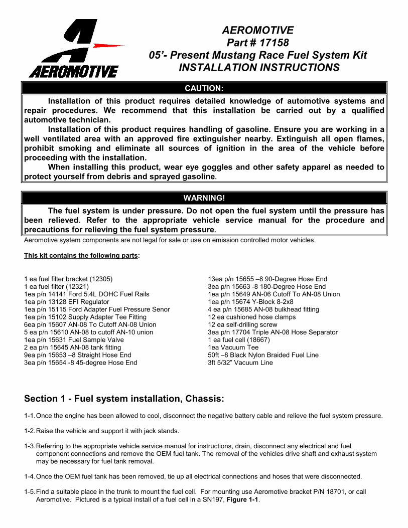
opposite side of the mounting bracket. 2-17. Install both fuel rails, being careful not to cut any of the o-rings during installation. 2-18. Find suitable place in the vehicle’s engine compartment to mount the Aeromotive regulator, typically on the
passenger side inner fender or shock tower. Using the supplied mounting bracket as a template, mark the bracket mounting holes and drill to accept a #10 screw.
2-19. With the bracket attached to the regulator, mount the bracket and regulator to the vehicle using two #10 screws,
nuts and lock washers. 2-20. Install one AN-10 o-ring on each of the two AN-10 to AN-08 union fittings (15610) and one AN-6 o-ring on the AN-6
to AN-08 fitting (15649).
2-21. Thread the side of the AN-10 cutoff’s with the o-ring into each of the two AN-10 ports on the regulator. Also do the
same for the AN-6 cutoff fitting in the return port on the bottom of the regulator.
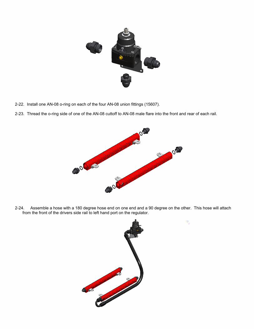
2-22. Install one AN-08 o-ring on each of the four AN-08 union fittings (15607). 2-23. Thread the o-ring side of one of the AN-08 cuttoff to AN-08 male flare into the front and rear of each rail.
2-24. Assemble a hose with a 180 degree hose end on one end and a 90 degree on the other. This hose will attach
from the front of the drivers side rail to left hand port on the regulator.
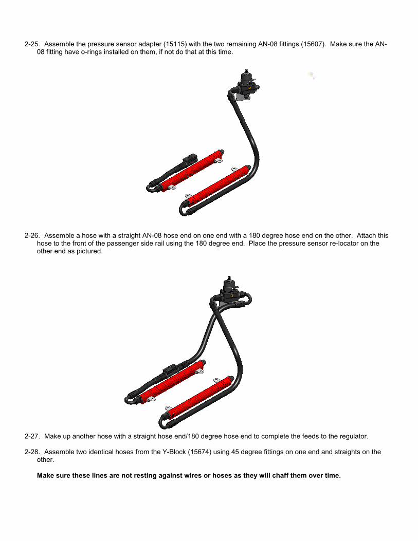
2-25. Assemble the pressure sensor adapter (15115) with the two remaining AN-08 fittings (15607). Make sure the AN-
08 fitting have o-rings installed on them, if not do that at this time.
2-26. Assemble a hose with a straight AN-08 hose end on one end with a 180 degree hose end on the other. Attach this
hose to the front of the passenger side rail using the 180 degree end. Place the pressure sensor re-locator on the other end as pictured.
2-27. Make up another hose with a straight hose end/180 degree hose end to complete the feeds to the regulator. 2-28. Assemble two identical hoses from the Y-Block (15674) using 45 degree fittings on one end and straights on the
other.
Make sure these lines are not resting against wires or hoses as they will chaff them over time.

2-29. Finish the pressure side of the system by assembling a hose with 90 degree hose ends at both ends. This will
make the connection between the feed bulk head and y-block.
2-30. Now connect the return side of the regulator (bottom port) to the return bulk head. This is done by using two 90
degree hose ends. This completes the engine bay fuel lines.
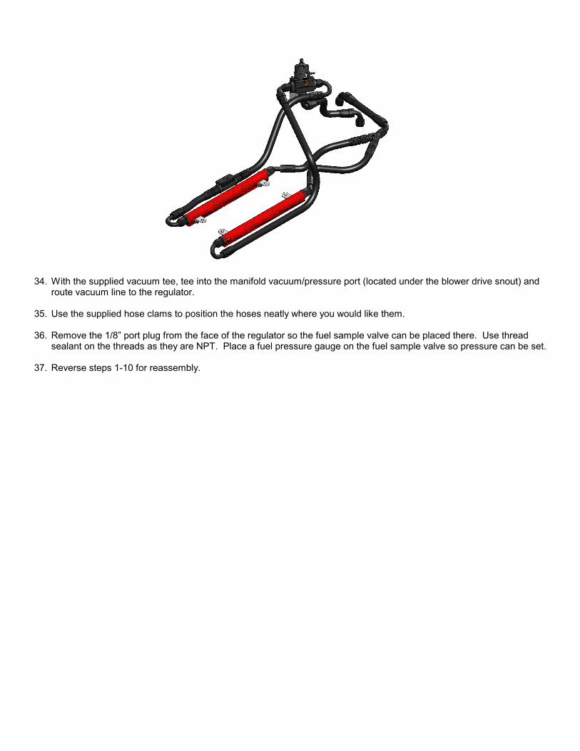
34. With the supplied vacuum tee, tee into the manifold vacuum/pressure port (located under the blower drive snout) and
route vacuum line to the regulator. 35. Use the supplied hose clams to position the hoses neatly where you would like them. 36. Remove the 1/8” port plug from the face of the regulator so the fuel sample valve can be placed there. Use thread
sealant on the threads as they are NPT. Place a fuel pressure gauge on the fuel sample valve so pressure can be set. 37. Reverse steps 1-10 for reassembly.
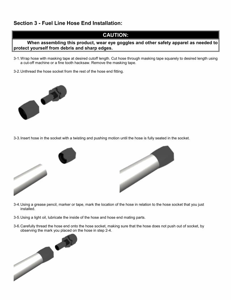
Section 3 - Fuel Line Hose End Installation:
CAUTION: When assembling this product, wear eye goggles and other safety apparel as needed to
protect yourself from debris and sharp edges. 3-1. Wrap hose with masking tape at desired cutoff length. Cut hose through masking tape squarely to desired length using
a cut-off machine or a fine tooth hacksaw. Remove the masking tape. 3-2. Unthread the hose socket from the rest of the hose end fitting.
3-3. Insert hose in the socket with a twisting and pushing motion until the hose is fully seated in the socket.
3-4. Using a grease pencil, marker or tape, mark the location of the hose in relation to the hose socket that you just
installed. 3-5. Using a light oil, lubricate the inside of the hose and hose end mating parts. 3-6. Carefully thread the hose end onto the hose socket, making sure that the hose does not push out of socket, by
observing the mark you placed on the hose in step 2-4.
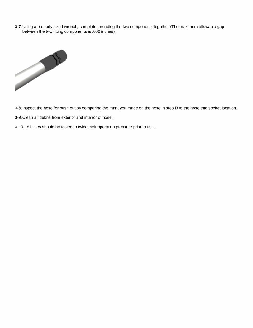
3-7. Using a properly sized wrench, complete threading the two components together (The maximum allowable gap
between the two fitting components is .030 inches).
3-8. Inspect the hose for push out by comparing the mark you made on the hose in step D to the hose end socket location. 3-9. Clean all debris from exterior and interior of hose. 3-10. All lines should be tested to twice their operation pressure prior to use.

Section 4 – Final Checks and System Start-up 4-1. Ensure that any spilled gasoline and any gasoline soaked shop towels are cleaned up and removed from the
vicinity of the vehicle! 4-2. Carefully lower the car onto the ground. 4-3. Fill the fuel tank with gasoline and check for any leaks in the system, if any leaks are found repair immediately. CAUTION: While performing the following steps, if any fuel leaks are detected, immediately turn the ignition of OFF, remove any spilled fuel and repair the leak(s) before proceeding! 4-4. Reconnect the battery and turn the ignition to the ON position WITHOUT starting the car. After several seconds, check
the fuel pressure. If there is no fuel pressure, turn the ignition key to the OFF position, wait one minute, return the ignition to the ON position, and recheck the fuel pressure. Repeat this ignition OFF and ON procedure until the fuel pressure gauge registers fuel pressure.
4-5. With the fuel pressure gauge registering fuel system pressure, check for fuel leaks throughout the entire fuel
system! If any fuel leaks are found, turn the ignition key to the OFF position, remove any spilled fuel and repair the leak before proceeding!
4-6. Once the fuel pressure gauge registers fuel system pressure and there are no fuel leaks, start the engine and adjust
the regulator to the desired fuel pressure. Turning the adjustment screw clockwise will increase fuel pressure. 4-7. Once the desired fuel pressure is achieved, tighten the regulator adjustment jam nut and attach the vacuum line. 4-8. Test drive the car to insure proper operation and re-check the fuel system for leaks. If any leaks are found,
immediately discontinue use of the vehicle and repair the leak(s)!

Aeromotive, Inc. 7805 Barton Street, Lenexa, KS 66214 Phone: (913) 647-7300 Fax: (913) 647-7207
AEROMOTIVE, INC. LIMITED WARRANTY This Aeromotive Product, with proof of purchase dated on or after January 1, 2003, is warranted to be free from defects in materials and workmanship for a period of one year from the original date of purchase. No warranty claim will be valid without authentic, dated proof of purchase. This warranty is to the original retail purchaser and none other and is available directly from Aeromotive and not through any point of distribution or purchase. If a defect is suspected, the retail purchaser must contact Aeromotive directly to discuss the problem, possible solutions and obtain a Return Goods Authorization (RGA), if deemed necessary by the company. Please call 913-647-7300 and dial option 3 for the technical service dept. All returns must be shipped freight pre-paid to the company and with valid RGA before they will be processed. Aeromotive will examine any product returned with the proper authorization to determine if the failure resulted from a defect or from abuse, improper installation, misapplication or alteration. Aeromotive will then, at it’s sole discretion, return, repair or replace the product. If any Aeromotive product is determined defective, buyer’s exclusive remedy is limited in value to the sale price of the good. In no event shall Aeromotive be liable for incidental or consequential damages.
Aeromotive expressly retains the right to make changes and improvements in any product it manufactures and sells at any time. These changes and improvements may be made without notice at any time and without any obligation to change the catalogs or printed materials. Aeromotive expressly retains the right to discontinue at any time and without notice any Aeromotive product that it manufactures or sells. This warranty is limited and expressly limits any implied warranty to one year from the date of the original retail purchase on all Aeromotive products. No person, party or corporate entity other than Aeromotive shall have the right to: determine whether or not this Limited Warranty is applicable to any Aeromotive product, authorize any action whatsoever under the terms and conditions of this Limited Warranty, assume any obligation or liability of any nature whatsoever on behalf of Aeromotive under the terms and conditions of this Limited Warranty. This Limited Warranty covers only the product itself and not the cost of installation or removal. This Limited Warranty is in lieu of and expressly excludes any and all other warranties, expressed or implied. This Limited Warranty gives you specific legal rights, and you may also have other rights which vary from state to state.