2017 march 31, 2017
TRANSCRIPT

2017 March 31, 2017

International Conference on Latest Innovations in Applied Science, Engineering and Technology (ICLIASET 2017), March 2017
©IJRASET: All Rights are Reserved 110
International Journal of Innovative Research in Science Engineering and Technology
Design of Aluminium Composite Helical Gear Using Finite Element Analysis
Raffek.S1
1Assistant Professor, Department Of Mechanical Engineering Arjun College of Technology, Coimbatore.
Abstract: Helical gears have become a subject of research interest because the dynamic load attention of the noise level during operation and the demand for lighter and smaller in size. In such type of gears there is a problem of failures at contact at meshing the teeth. This can be avoided or minimized by proper method analysis and modification of the different gear parameters. In this project characteristics of a helical gear in dynamic condition involving contact stiffness and other stresses produce. The main purpose of this thesis is by using numerical approach to develop theoretical model of helical gear and to determine the effect of contact gear tooth stresses for a safe design by taking material alloy steel and later on design after this study the composite applications in form of MMC and laminate technology is introduced on forming of gear structure with composite materials and various case studies is involved in determining the better dynamic strength for load carrying capacity, minimizing the vibration and improving the fatigue life of the gear. Application of laminates in the gear will prevent propagation and penetration of crack along the width of gear. To estimate the meshing stiffness, three-dimensional solid models for different number of teeth are generated by solid works and the numerical solution is done in ANSYS, which is a finite element analysis package. In recent days engineering components made of composite materials find increasing applications ranging from spacecraft to small instruments. In this project, for a transmission system for high speed engine of Helical gear pair made of Alloy steel, AL-SiC material metal matrix composite and for a composite laminate Helical gear pair Alloy steel and Al-SiC (MMC) combinations , stress analysis is made under static load conditions using ANSYS and the results were compared. Keywords: Aluminum, Al-Sic, Metal Matrix Composite, Laminate, Aerospace,
I. INTRODUCTION Gears defined as toothed members transmitting power and motions from one shaft to another are the oldest devices and inventions of man. The smaller gear is called as pinion and the larger gear is called as gear wheels. Gears are employed when a constant speed ratio is desired and the distance between the shafts are relatively small. This gear drives are widely used in various kinds of machines. Gears are one of the most critical components in mechanical power transmission systems. The bending and surface strength of the gear tooth are considered to be one of the main contributors for the failure of the gear in a gear set. Understanding of their behavior becomes essential to design and implement them effectively. Thus, analysis of stresses has become popular as an area of research on gears to minimize or to reduce the failures and for optimal design of gears. This thesis investigates the characteristics of involutes helical gear system mainly focused on bending and contact stresses using analytical and finite element analysis. A rigid multi body model is required to be simulated. The model consists of a helical gear pair where Gear contact is characterized by angle-varying mesh stiffness and a backlash which can lead to loss of the contact. Angle-varying mesh stiffness shall be calculated using a finite element model. In helical gears there is a problem of failures at the root of the teeth because of the inadequate bending strength and surface pitting. This can be avoided or minimized by proper method and modification of the different gear parameters. In view of this the main purpose of this work is by using analytical approach and numerical approach to develop theoretical model of helical gear in mesh and to determine the effect of gear tooth stresses.
II. OBJECTIVES OF THE STUDY A. An another objective of this project is to changed composition of ALSIC metal of helical gear
International Conference on Latest Innovations in Applied Science, Engineering and Technology (ICLIASET 2017), March 2017
©IJRASET: All Rights are Reserved 111
B. To provide a guidelines in working with the root causes analysis for every crack and its propagation C. To another objective of project is laminates the helical gear D. Analysis is being carried out using FEM and FEA
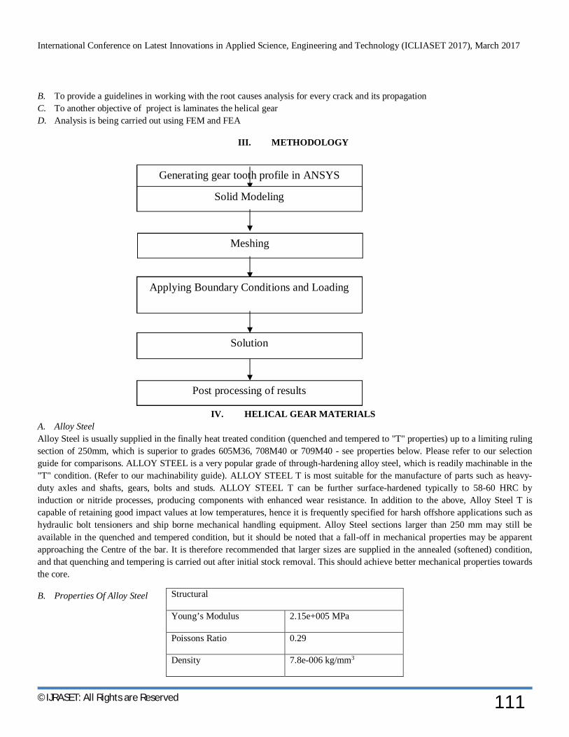
III. METHODOLOGY
IV. HELICAL GEAR MATERIALS A. Alloy Steel Alloy Steel is usually supplied in the finally heat treated condition (quenched and tempered to "T" properties) up to a limiting ruling section of 250mm, which is superior to grades 605M36, 708M40 or 709M40 - see properties below. Please refer to our selection guide for comparisons. ALLOY STEEL is a very popular grade of through-hardening alloy steel, which is readily machinable in the "T" condition. (Refer to our machinability guide). ALLOY STEEL T is most suitable for the manufacture of parts such as heavy-duty axles and shafts, gears, bolts and studs. ALLOY STEEL T can be further surface-hardened typically to 58-60 HRC by induction or nitride processes, producing components with enhanced wear resistance. In addition to the above, Alloy Steel T is capable of retaining good impact values at low temperatures, hence it is frequently specified for harsh offshore applications such as hydraulic bolt tensioners and ship borne mechanical handling equipment. Alloy Steel sections larger than 250 mm may still be available in the quenched and tempered condition, but it should be noted that a fall-off in mechanical properties may be apparent approaching the Centre of the bar. It is therefore recommended that larger sizes are supplied in the annealed (softened) condition, and that quenching and tempering is carried out after initial stock removal. This should achieve better mechanical properties towards the core.
B. Properties Of Alloy Steel
Structural
Young’s Modulus 2.15e+005 MPa
Poissons Ratio 0.29
Density 7.8e-006 kg/mm3
Generating gear tooth profile in ANSYS
Solid Modeling
Meshing
Applying Boundary Conditions and Loading
Solution
Post processing of results

International Conference on Latest Innovations in Applied Science, Engineering and Technology (ICLIASET 2017), March 2017
©IJRASET: All Rights are Reserved 112
Thus the above mentioned materials (ALLOY STEEL & Al-SiC) are used as the materials for helical gear pair and the stress analysis between these two materials of the results are compared finally.
C. Al-Sic (Aluminium Silicon Carbide) AlSiC composites are suitable replacements for copper-molybdenum (CuMo) and copper-tungsten (CuW) alloys; they have about 1/3 the weight of copper, 1/5 of CuMo, and 1/6 of CuW, making them suitable for weight-sensitive applications; they are also stronger and stiffer than copper. They are stiff, lightweight, and strong. They can be used as heat sinks, substrates for power electronics (e.g. IGBTs and high-power LEDs), heat spreaders, housings for electronics, and lids for chips, e.g. microprocessors and ASICs. Metal and ceramic inserts and channels for a coolant can be integrated into the parts during manufacture. AlSiC composites can be produced relatively inexpensively (USD 2-4/lb in large series); the dedicated tooling however causes large up-front expenses, making AlSiC more suitable for mature designs. Heat pipes can be embedded into AlSiC, raising effective heat conductivity to 500–800 W/m K.AlSiC parts are typically manufactured by near net shape approach, by creating a SiC preform by metal injection molding of a SiC - binder slurry, fired to remove the binder, then infiltrated under pressure with molten aluminum. Parts can be made with sufficiently low tolerances to not require further machining. The material is fully dense, without voids, and is hermetic. High stiffness and low density appears making larger parts with thin wall, and manufacturing large fins for heat dissipation. AlSiC can be plated with nickel and nickel-gold, or by other metals by thermal spraying. Ceramic and metal insets can be inserted into the preform before aluminum infiltration, resulting in a hermetic seal. AlSiC can be also prepared by mechanical alloying. When lower degree of SiC content is used, parts can be stamped from AlSiCsheets. The aluminum matrix contains high amount of dislocations, responsible for the strength of the material. The dislocations are introduced during cooling by the SiC particles, due to their different thermal expansion coefficient. A similar material with copper-silver alloy instead of aluminum and diamond instead of silicon carbide. Other materials are copper reinforced with carbon fiber, diamond-reinforced aluminum, reinforced carbon-carbon, and pyrolytic graphite.
D. Properties of Al-Sic
E. Laminated Gear A Helical gear formed of a laminated stack of axially thin helical gear elements having helically extending teeth identical involute tooth profiles and with means for securing them together in coaxial relation with stepped increments of phase between them on producing a gear. In some designs, it is advantageous to use laminated gearing specifically, in fine-pitch formed gearing (molded plastic, die cast, powder metal, stamped), tolerances are often so large relative to whole depth that the contact ratio is less than unity. In that case, it is necessary to use laminated gearing, note should be taken of the fact that tooling for laminated gearing is more accurate.
F. Materials Used For Helical Gear 1) CASE-1Alloy Steel 2) CASE -2 Aluminum Silicon Carbide = Al-SiC (MMC) 3) CASE -3 Gear Section 1, 3, &5 Alloy Steel
Gear Section 2&4 Al-SiC (MMC) CALCULATIONS FOR STEEL [40 Ni2 Cr1 Mo28 STEEL] FT=137572.60 N FR =55248.70 N
Structural
Youngs Modulus 2.3e+005 MPa
Poissons Ratio 0.24
Density 2.937 e-006 kg/mm3

International Conference on Latest Innovations in Applied Science, Engineering and Technology (ICLIASET 2017), March 2017
©IJRASET: All Rights are Reserved 113
Calculated Geometry Details For Helicalpair S.NO. PARTICULARS PINION GEAR 1. Speed. 3500 rpm 2. Power Transmission (P) 9000 kw 3. Gear Ratio 7 4. Helix Angle 25 deg 5. Pressure angle 20 deg 6. No of teeth 18 126 7. Diameter 357.4 mm 2502.4 mm 8. Tip circle diameter 393 mm 2538 mm 9. Root circle diameter 312.4 mm 2457.4 mm 10. Module (Mn) 18 11. Face width 430 mm 12. Center distance 1429.9 mm
V. BOUNDARY CONDITIONS A. Geometry boundary conditions The shaft is fixed at the Centre along with its key.
B. Loads applied FT=137572.60 N FR =55248.70 N Finally the boundary conditions are verified before going for a solution. Total Deformation Result For Alloy Steel
Normal X Stress (Bending) - Alloy Steel

International Conference on Latest Innovations in Applied Science, Engineering and Technology (ICLIASET 2017), March 2017
©IJRASET: All Rights are Reserved 114
Total Deformation Result For Al-Sic
Total Deformation Result For Alloy Steel +Al-Sic Laminates

International Conference on Latest Innovations in Applied Science, Engineering and Technology (ICLIASET 2017), March 2017
©IJRASET: All Rights are Reserved 115
Normal X Stress (Bending) Al-Sic
Alloy Steel +Al-Sic Laminates
Normal Y Stress (Bending) Al-Sic

International Conference on Latest Innovations in Applied Science, Engineering and Technology (ICLIASET 2017), March 2017
©IJRASET: All Rights are Reserved 116
Normal Y Stress (Bending)Alloy Steel +Al-Sic Laminates
Equivalent Stress For Al-Sic

International Conference on Latest Innovations in Applied Science, Engineering and Technology (ICLIASET 2017), March 2017
©IJRASET: All Rights are Reserved 117
Equivalent Stress For Alloy Steel +Al-Sic Laminates

International Conference on Latest Innovations in Applied Science, Engineering and Technology (ICLIASET 2017), March 2017
©IJRASET: All Rights are Reserved 118
VI. RESULTS A. Comparision With Theoretical
PARAMETER ALLOY STEEL (calculated)
ALLOY STEEL (Ansys)
Total deformation (mm) 0 0.107 Normal X Stress (compression) Mpa 228 226 Normal Y Stress (compression ) Mpa 180 143 Equivalent stress (MPa) 650 (allowed) 436
B. Consolidation Of Results For Composites
PARAMETER AL-Sic ( MMC )
ALLOY STEEL + AL-Sic LAMINATES
Total deformation (mm) 0.09 0.117 Normal X Stress (compression) Mpa 221 227 Normal Y Stress (compression )Mpa 132 116 Equivalent stress (MPa)
449 336
C. Application Of Gears 1) Gearbox of a motor cycle 2) Sliding mesh gearbox of an automobile 3) Differential drive 4) Conveyors 5) In industrial machineries
VII. CONCLUSION It is seen that for laminates (ALLOY STEEL+AL-SIC (MMC)) Material to be used in Gear boxes. Certain criteria must be met. Although the exact set of required properties depend on the specific application.According to equivalent stress of AL-SIC (MMC) is (449 MPA) which is higher than the value of laminates from the result.
REFERENCES [1] Suryanarayanan K., R. Praveen and S. Raghuraman (2013), “Silicon Carbide Reinforced Aluminium Metal Matrix Composites for Aerospace Applications”.
International Journal of Innovative Research in Science, Engineering and Technology, Vol. 2, Issue 11, November 2013, pp.6336-6344. [2] JuSeok Kang and Yeon-Sun Choi (2008), “Optimization of helix angle for helical gear system”, Journal of Mechanical Science and Technology,Vol 22 (2008) ,
pp.2393-2402. [3] J.E.Shigley, J.J.Uicker Jr., “Theory of Machines and Mechanisms”, McGraw-Hill, New York 1995. [4] R.S.Khurmi, J.K.Gupta, “A Textbook of Machine Design”, Eurasia Publishing House, New Delhi, 2005. [5] DarlyL.Logan, “The Finite Element and Boundary Element Methods”. [6] J.D.Andrews, “A Finite Element Analysis of Gears”. [7] Mark Occhionero, Richard Adams, Kevin Fennessy, and Robert A. Hay “Aluminum Silicon Carbide (AlSiC) for Advanced Metal Matrix Composites”. [8] Jose I. Pederero, Miguel Pleguezuelos, Marta Munoz, “Contact stress calculation of spur gear”. [9] Chien- Hsing Li, Hong-Shun Chiou, Chinghua Hung, Yun- Yuan Chang, Cheng-Chung Yen, “Integration of finite element analysis and optimum design on
gear system”. [10] V.G.Sfakiotakis, N.K.Anifantis, “Finite element modelling on spur gearing fractures”. [11] R.W. Adams, B.E. Novich, D.Kane, K.Brantferger and R.Oberle, “A Lightweight high Thermal Conductivity Metal Matrix Composite”.
