202 owner's manual - amish and more owner… · when properly maintained and operated within...
TRANSCRIPT

0713
RD-202SHeavy-Duty Tandem Drive Truck SuspensionOwner’s Manual
www.ridewellcorp.comP.O. Box 4586 Springfield, MO 65808 417.833.4565 417.833.4560 (fax)

Suspension Identifi cation:
Parts:
Sales, Service & Warranty:
Ridewell Suspensions are identifi ed by a metal tag attached to the pedestal that indicates part number, revision level, and serial number.
For optimum suspension performance, order only Ridewell parts. Replacement parts for Model RD-202S are shown on pages 9-13 of this manual.
If you need assistance regarding this product, please contact us and we will be glad to help you.
Mailing Address
Ridewell CorporationP.O. Box 4586Springfi eld, MO 65808
Shipping Address
Ridewell Corporation3715 East Farm Rd. 94Springfi eld, MO 65803
Phones, Fax, E-mail
800.641.4122, 417.833.4565417.833.4560 (fax)[email protected]

RD-202S Owner’s Manual
3
Contents
Basic Operation...................................................................................................................3
Operational Inspection........................................................................................................4
Preventative Maintenance....................................................................................................5
Basic Troubleshooting.........................................................................................................6
Bushing & Elastomer Replacement Procedure......................................................................7
Shock Absorber Adjustment................................................................................................8
Parts Illustrations...........................................................................................................9-17
Being a single-point design suspension, all the load is fi rst transmitted from the frame to the center bushing. Th ere, the load is equally distributed along the compensator. Elastomer (rubber) springs housed at the ends of the compensator defl ect according to load applied and transmit this load to the independent torque arms and engage as the suspension reaches a given load defl ection. Th e overload springs act as an assist for the main load-carrying elastomer springs. Th e interaction of the components provide the vehicle with an exceptionally fi ne ride, both in a loaded and unloaded condition.
As the vehicle encounters a bump, the independent torque arms for the elastomer spring go into compression. Th is compression is absorbed in the compensator and equalizes the bump’s dynamic force between front and rear elastomer springs before reaching the chassis of the vehicle.
How the Suspension Works
When properly maintained and operated within design limits, Ridewell’s Dynalastic Model RD-202S will provide many years of trouble-free service.
Th e RD-202S provides the heavy-duty truck industry with a versatile tandem suspension. It has proven durability in refuse, military, fi refi ghting, logging and construction applications for four continents.
Basic Operation

RD-202S Owner’s Manual
4
Operational Inspection
1. Inspect all fasteners at the pedestal clamp and pedestal to frame connections. Refer to torque chart for proper torque requirements.
2. Inspect elastomer springs.
3. Inspect shocks and shock attach points.
4. Inspect torque beam end bushings and axle attachments.
Figure 1

RD-202S Owner’s Manual
5
Preventative Maintenance
Daily
Check for loose or broken parts on or around suspension. If loose or broken parts are detected, immediate corrective action must be taken.
6,000 Miles
After suspension has been in operation for approximately 6,000 miles (10,000 KM), all fasteners must be re-tightened to specifi ed torque.
Every 30 Days
Check clearances around all moving suspension parts, tires, and shock absorbers. Any signs of interference should be corrected immediately.
Every 90 Days & with Annual Inspection
Inspect items required in daily & 30-day inspections.
Inspect all welded connections.
Inspect all pivot and clamping connections such as the suspension pivots, elastomer springs, and shock mounts.
50,000 Miles
All fasteners must be re-tightened to specifi ed torque. Repeat every 50,000 miles.
#1990020
DO NOT OVER TORQUE!
DONOTPAINT THIS STICKER
After suspension has been in operation for approximately6,000 miles (10,000 km), all fasteners must be re-tightenedto specified torque. Repeat every 50,000 miles (80,000 km).
RIDEWELL SUSPENSIONS TORQUE CHARTBOLT SIZE LUBRICATED THREADS
1 ½” 1,100 FT. LB. (1,490 N•m)1 ¼” 1,000 FT. LB. (1,350 N•m)1 1/8” 500 FT. LB. (680 N•m)
1” GRADE 5 360 FT. LB. (490 N•m)1” GRADE 8 460 FT. LB. (625 N•m)
7/8” 350 FT. LB. (475 N•m)¾” GRADE 5 160 FT. LB. (220 N•m)¾” GRADE 8 190 FT. LB. (260 N•m)5/8” 100 FT. LB. (135 N•m)*¾” 50 FT. LB. (70 N•m)*½” 25 FT. LB. (35 N•m)
*AIR SPRING CONNECTION ONLY
Figure 2

RD-202S Owner’s Manual
6
Basic Troubleshooting
1. Vehicle pulls to left or right - check the following:
a. Tire pressure b. All suspension bushings
2. Vehicle has excessive sway - check the following:
a. Sway bar b. Torque beam bushings c. Center bushing
3. Vehicle has axle walk or hop - check the following:
a. Torque beam bushings b. Center bushings
4. Mounting height has changed - check the following:
a. Elastomer springs b. Compensator c. All suspension bushings

RD-202S Owner’s Manual
7
Bushing & Elastomer Replacement Procedure
It is recommended that torque beam pivot bushings and elastomer springs be replaced
in pairs for maximum suspension performance.
1. Remove vehicle weight from suspension by raising and blocking vehicle chassis and axles. Remove tires and wheels.
2. Remove axle/axle bracket assembly from torque beams.
3. Remove shock absorbers.
4. Remove elastomer spring fasteners from compensator.
5. Remove locking plate from torque beam/compensator pivot bolt and remove 1½” bolt.
6. Remove torque beam/elastomer spring assembly from compensator.
7. Inspect torque beam pivot bushing, end beam bushing, elastomer spring, and overload spring for damage or excessive wear.
8. Replace defective parts using only genuine Ridewell replacement parts.
9. After servicing the assembly, re-assemble the supension by reversing this procedure.
10. It is imperative that all fasteners be tightened to specifi ed torque and bolt locking plates be re-installed on bolt heads.
11. If you require additional assistance, please contact Ridewell Corporation.

RD-202S Owner’s Manual
8
Shock Absorber Adjustment
If your suspension is equipped with Koni adjustable shock absorbers and requires adjustment, proceed as follows:
NOTE: READ THIS ENTIRE PROCEDURE BEFORE STARTING.
1. Remove the shock absorber from the vehicle and holt it vertically with the lower eye in a vice.
2. Press top of shock down while turning gently counter-clockwise until you feel the cams of the adjusting nut engage in the recesses of the front valve assembly. When engagement is made, turn top of shock 2 half turns clockwise and stop. Adjustment is complete.
3. Pull top of shock up about ½” and remove from vice.
4. Re-install on vehicle.
IMPORTANT NOTE:
Shock absorbers must be adjusted in pairs. There is a minimum of 5 half turns clockwise
adjustment on your shock absorber. Do not use excessive force when making adjustments. If
you are having diffi culty, please contact Ridewell.

RD-202S Owner’s Manual
9
Parts Illustrations
Parts List
DESCRIPTIONPART NO.ITEM
SHOCK ASSY - GABRIEL1252607B000 1
SHOCK ASSY - KONI. BUSHINGS INCLUDED1265478B000
L'NUT 1" 8NC THIN W/ NYL, GR 2, Z PLA1155939B1022
WASHER 1" SAE FLAT ZINC1161677B1003
STRADDLE MOUNT PEDESTAL SMPA 202S -------4
L'NUT 7/8" 14NF TOP LOCK, GR 5 (B), Z PLA1154718B1055
WASHER 7/8" TYPE B NAR .1 THICK Z PLA1164718B1006
7/8 X 6 CLAMP BLOCK STUD1287594B0007
CAST COMP CAP MCH'D 3.5ID 7" 1747564B0018
OVERLOAD SPRING J19368_ (1-4)1037261C00_9
ELASTOMER SPG J19576-_ (1-4) 1037326D00_10
HHCS 1-1/2"-6NC x 7" LG GR 5 ZINC PLATED1130670B10511
HHCS 5/8" 18NF 1"LG. GR 5, ZINC PLATE1140665B10512
HHCS 5/8" 18NF 1-1/4"LG GR 5, ZINC PLATE 1142735B105 13
HHCS 5/8" 11NC 7"LG GR 8, ZINC PLATE1147414B10814
L'NUT 5/8" 11NC OVAL FLANGED 1157048B10815
WASHER- BEARING SLEEVE1160519B30216
DESCRIPTIONPART NO.ITEM
L'WASHER 5/8" S/T MED ZINC PLATE 1160598B100 17
L'WASHER 1-1/2" INT TOOTHLOCK 1160673B000 18
RETAINER KIT M.D. 3" x 6" 1304398B00019
RETAINER KIT 2.5" X 5.75"1307564B001
RETAINER KIT 2.5" X 6"1304963B000
RETAINER KIT 3" X 7"1307561B000
BUSHING CENTER 4.75" X 7" BONDED1117558B00020
COMPENSATOR ASS'Y 40" / 42"-------21
TORQUE BEAM ASS'Y - LH-------22
TORQUE BEAM ASS'Y - RH-------23
S'BLK BUSH 6"X6"X3"1114398B00024
S'BLK BUSH 5.75" X 2.5"1117564B001
S'BLK BUSH 6" X 2.5"1114964B000
S'BLK BUSH 7" X 6" X 3"1117561B000
BUSHING 3.13ODX1.5IDX4.42LG UR112001625
LOCKING PLATE9004565B00026
TUBE 1.25OD .28W 5.22"LG 9117340B31827
C'TUBE 2.44"OD. x 44.88"LG. .356W.9127564B00028
SHOCK BUSHING (GABRIAL SHOCKS ONLY)1102608B00029
2
3
28
4
21
5
6
7
8
14
27
15
16
25
12
17
23
24
19
1012
17
16
1
1118
26
13
17
22
20
9
NOTES: 1 - ITEMS PER CUSTOMER REQUIREMENTS. CONTACT RIDEWELL CUSTOMER SERVICE FOR PART NUMBERS AND SPECIFICATIONS 2 - 4 OPTIONS AVAILABLE, CONTACT RIDEWELL CUSTOMER SERVICE FOR PART NUMBERS AND SPECIFICATIONS 3 - ITEM 29 MUST BE ORDERED WITH GABRIEL SHOCKS
11111
1
22
11
113
29 3
1
1
11
1
1
1
1
1
22

RD-202S Owner’s Manual
10

RD-202S Owner’s Manual
11

RD-202S Owner’s Manual
12

RD-202S Owner’s Manual
13

RD-202S Owner’s Manual
14

RD-202S Owner’s Manual
15
RD-202S Owner’s Manual
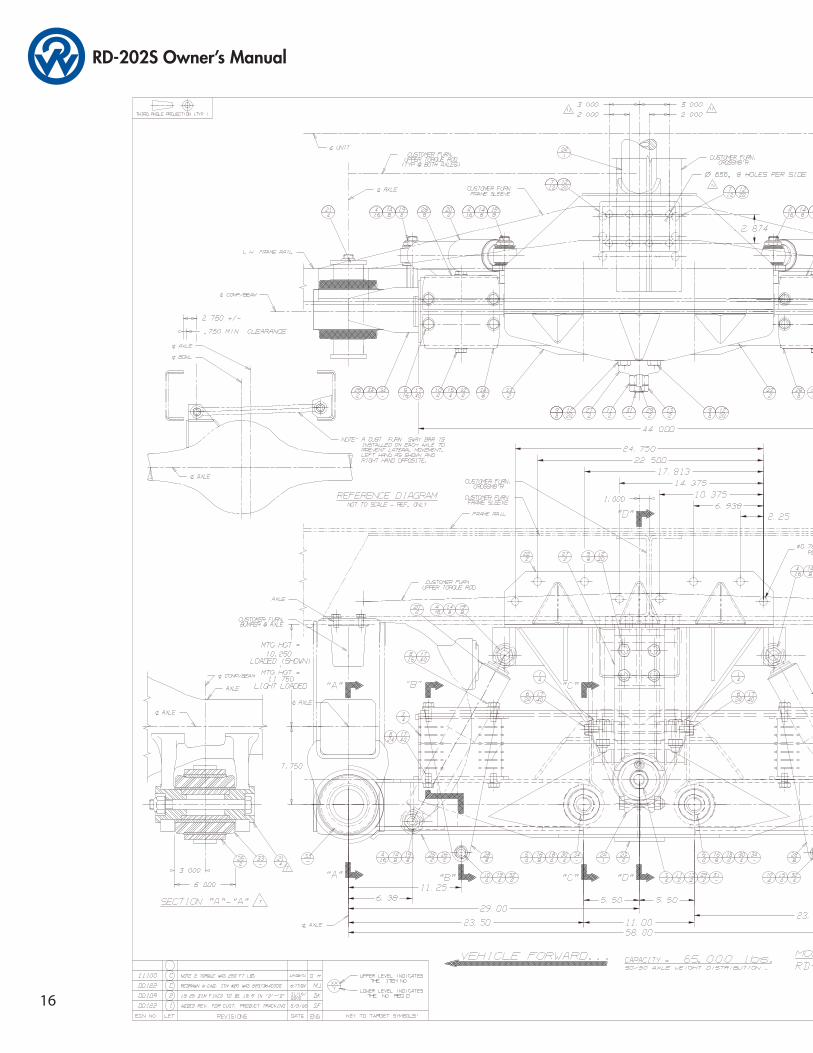
16

RD-202S Owner’s Manual
17