2021~ gv80 (jx1) tow hitch (t6f61 au000 600) eng isheet
TRANSCRIPT
Genuine Accessories
Electronic Installation Instructions
Glasses Gloves
Mask Hearing Protection
Part Weight (Gross) FMVSS 110 Compliance Information
1) Read the entire Installation Instructions prior to beginning the installation of this accessory.2)
3) Make sure the vehicle is completely clean and dry in the area(s) the part is to be installed.4) Ensure the vehicle is properly protected in the area(s) that the accessory is to be installed.5) NEVER place tools on painted surfaces, seating surfaces, dash pad, console or floor carpet/mats.6) Always wear appropriate personal protective equipment, including gloves, safety glasses, etc., when required.7) Roll down the driver's window and adjust the power seats (if applicable) prior to disconnecting battery power, if needed.8) Vehicle should be at room temperature to avoid physical injury from hot exhaust system.
If applicable, scan the barcode label located on the accessory part or packaging prior to installing, to register the part. If this accessory is installed as a replacement, register the removal of the old part before registering the new part. Old and new parts will have different barcode data, and the old registration cannot be reused.
Specialty Required Tools
Vehicle Lift
Channel Locks
Notes to the installer:
Basic Required Tools
NOTE
Exhaust HangerRemoval Tool
19mm SocketTorque Wrench
M12-1.25 Thread Chaser
Extension
Yellow or White Paint Pen
Ratchet 10mm Socket
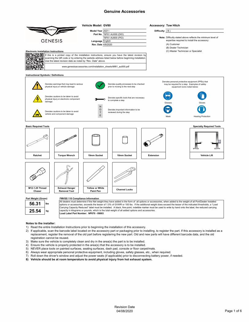
(C) Master Technician or Specialist
(B) Dealer Technician
Denotes cautions to be taken to avoid vehicle and component damage
Denotes cautions to be taken to avoid physical injury or electronic component damage
Instructional Symbols / Definitions
Denotes quality processes to be checked prior to moving to the next step
Denotes personal protective equipment (PPEs) that may be required for a step. Examples of safety
equipment icons noted below:Denotes warnings that may lead to serious physical injury or vehicle damage
Denotes important information to be reviewed during the step
Denotes specific tools that are necessary to complete a step
Entered by MPA
If this is a printed copy of the installation instructions, ensure you have the latest revision byscanning the QR code or by entering the website address listed below before beginning installation.Use the latest revision date as noted by “Rev. Date” above.
www.genesisaccessories.com/installation_sheets/t6f61_au000.pdf
Language English
4/8/2020Rev. Date
Accessory:GV80Vehicle Model:
Difficulty stated above reflects the minimum level of expertise required to install the accessory:
( B )
Tow Hitch
(A) Customer
Part No.
Model YearCopy OEM Logo Here (→)
2021~
T6F61 AU000 (DIO)
Difficulty:
Note:T6F61 AU600 (PIO)
56.31 lbsAll dealers must determine if the Net weight they have added in the form of all options or accessories, when added to the weight of all Port/Dealer Installed options or accessories, exceeds the lesser of 1.5% of GVWR or 100 lbs. If the additional weight does exceed the lesser of the indicated thresholds, a “Load Carrying Capacity Reduced” label must be installed. A black, fine-point, indelible marker must be used to write by hand onto the label, the reduced carrying capacity in kilograms or pounds, which is the total weight of all added options and accessories. Load Label Part Number: NP070 - 09003
25.54 kg
Revision Date04/08/2020 Page 1 of 6
Genuine Accessories
No.12345
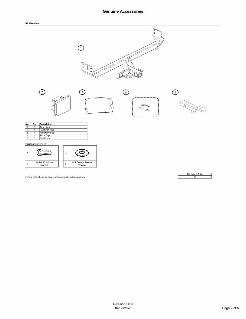
Hardware Overview
8 8
Follow instructions for proper placement of each component.
M12-1.25x40mmHex Bolt
Ball Mount
1Receiver Plug1
Pin & ClipHardware Bag1
11
Kit Overview
DescriptionTow Hitch
Qty
A
Hardware Total16
B
M12 Conical Toothed Washer
2 3 4 5
1
Revision Date04/08/2020 Page 2 of 6
Genuine Accessories
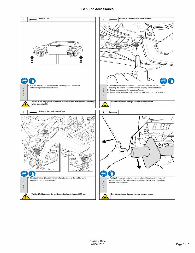
2 Ratchet, Extension and 10mm Socket
A. Position vehicle on a vehicle lift and raise to gain access to the undercarriage near the rear bumper.
Vehicle Lift1
NOTE
NOTE
WARNING: Make sure the muffler and exhaust tips are NOT hot.
4
Do not scratch or damage the rear bumper cover.
WARNING: Comply with vehicle lift manufacture's instructions and safety when using the lift.
A. Starting at the driver's side rear bumper area, remove the two (2) nuts securing the bottom exhaust bezel and carefully remove the bezel.B. Repeat procedure on the passenger's side.C. Store the hardware and both bezels in a safe location for reinstallation.
NOTE
A. Pull lightly rearward on bumper cover exhaust locations on driver and passenger side of vehicle then carefully lower the exhaust beyond the bumper area as shown.
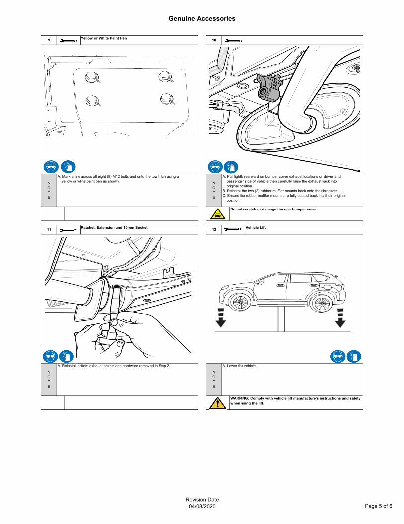
Do not scratch or damage the rear bumper cover.
3
NOTE
A. Dislodge the two (2) rubber hangers from the sides of the muffler using an exhaust hanger removal tool.
Exhaust Hanger Removal Tool
Revision Date04/08/2020 Page 3 of 6
Genuine Accessories
NOTE
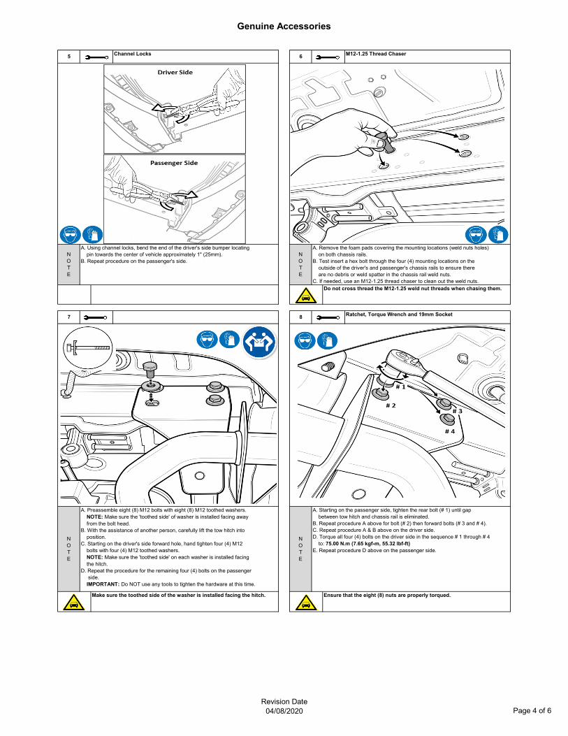
Make sure the toothed side of the washer is installed facing the hitch.
A. Using channel locks, bend the end of the driver's side bumper locating pin towards the center of vehicle approximately 1" (25mm). B. Repeat procedure on the passenger's side.
7
NOTE
A. Preassemble eight (8) M12 bolts with eight (8) M12 toothed washers. NOTE: Make sure the 'toothed side' of washer is installed facing away from the bolt head.B. With the assistance of another person, carefully lift the tow hitch into position.C. Starting on the driver's side forward hole, hand tighten four (4) M12 bolts with four (4) M12 toothed washers. NOTE: Make sure the 'toothed side' on each washer is installed facing the hitch.D. Repeat the procedure for the remaining four (4) bolts on the passenger side. IMPORTANT: Do NOT use any tools to tighten the hardware at this time.
8 Ratchet, Torque Wrench and 19mm Socket
NOTE
A. Remove the foam pads covering the mounting locations (weld nuts holes) on both chassis rails.B. Test insert a hex bolt through the four (4) mounting locations on the outside of the driver's and passenger's chassis rails to ensure there are no debris or weld spatter in the chassis rail weld nuts.C. If needed, use an M12-1.25 thread chaser to clean out the weld nuts.
Do not cross thread the M12-1.25 weld nut threads when chasing them.
M12-1.25 Thread Chaser
Ensure that the eight (8) nuts are properly torqued.
A. Starting on the passenger side, tighten the rear bolt (# 1) until gap between tow hitch and chassis rail is eliminated.B. Repeat procedure A above for bolt (# 2) then forward bolts (# 3 and # 4).C. Repeat procedure A & B above on the driver side.D. Torque all four (4) bolts on the driver side in the sequence # 1 through # 4 to: 75.00 N.m (7.65 kgf-m, 55.32 lbf-ft)E. Repeat procedure D above on the passenger side.
NOTE
5 6Channel Locks
Revision Date04/08/2020 Page 4 of 6
Genuine Accessories
Yellow or White Paint Pen9
Ratchet, Extension and 10mm Socket
NOTE
11
NOTE
A. Mark a line across all eight (8) M12 bolts and onto the tow hitch using a yellow or white paint pen as shown.
Do not scratch or damage the rear bumper cover.
NOTE
10
12
WARNING: Comply with vehicle lift manufacture's instructions and safety when using the lift.
A. Lower the vehicle.
Vehicle Lift
NOTE
A. Pull lightly rearward on bumper cover exhaust locations on driver and passenger side of vehicle then carefully raise the exhaust back into original position.B. Reinstall the two (2) rubber muffler mounts back onto their brackets.C. Ensure the rubber muffler mounts are fully seated back into their original position.
A. Reinstall bottom exhaust bezels and hardware removed in Step 2.
Revision Date04/08/2020 Page 5 of 6
Genuine Accessories
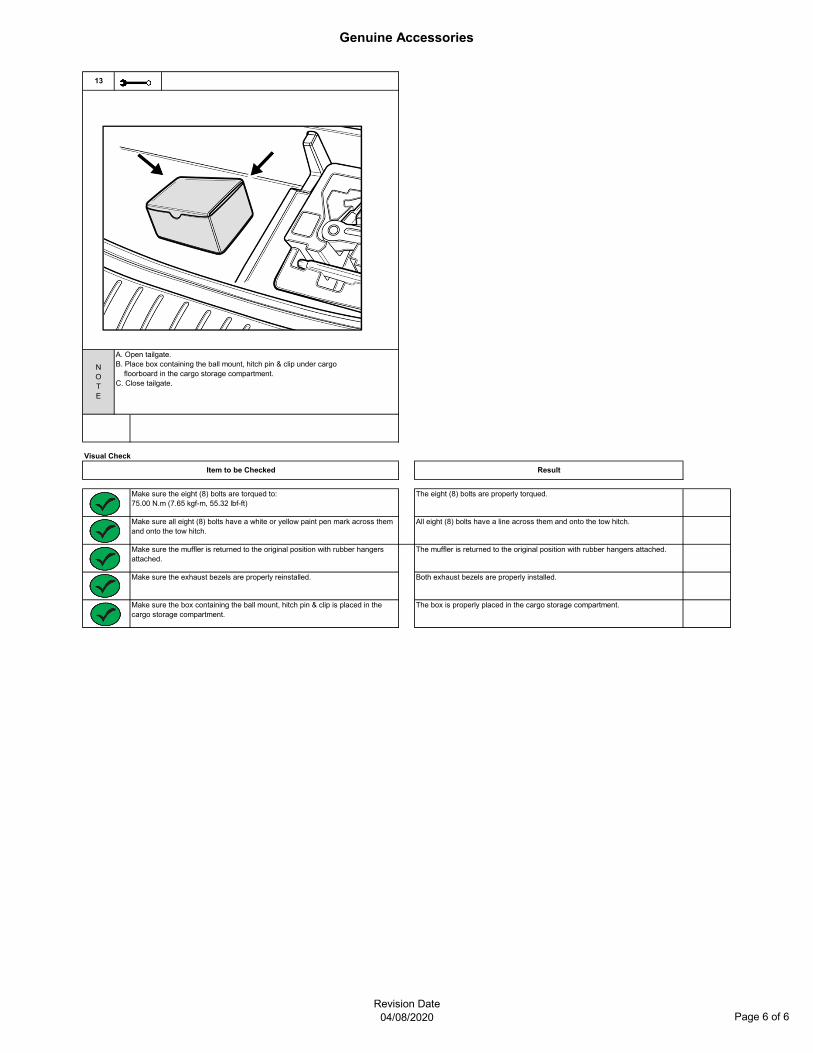
Make sure the exhaust bezels are properly reinstalled.
Visual Check
Item to be Checked
The eight (8) bolts are properly torqued.
The box is properly placed in the cargo storage compartment.
All eight (8) bolts have a line across them and onto the tow hitch.
Make sure the muffler is returned to the original position with rubber hangers attached.
Make sure the box containing the ball mount, hitch pin & clip is placed in the cargo storage compartment.
Make sure all eight (8) bolts have a white or yellow paint pen mark across them and onto the tow hitch.
Make sure the eight (8) bolts are torqued to:75.00 N.m (7.65 kgf-m, 55.32 lbf-ft)
Result
The muffler is returned to the original position with rubber hangers attached.
Both exhaust bezels are properly installed.
13
NOTE
A. Open tailgate.B. Place box containing the ball mount, hitch pin & clip under cargo floorboard in the cargo storage compartment.C. Close tailgate.
Revision Date04/08/2020 Page 6 of 6