2021 southwest geotechnical engineering conference design
TRANSCRIPT

6/24/2021
1
1
Design of geosynthetic-reinforced column-supported embankments:
A unified approach
Jie Han, Ph.D., PE, F.ASCE
Glenn L. Parker Professor
The University of Kansas
2021 Southwest Geotechnical Engineering Conference
2
2005
Theory
Practice
The 3rd Robert M. Koerner Award LectureGeosynthetic‐Reinforced Column‐Supported Embankments: Bridging Theory and Practice

6/24/2021
2
3
Introduction Mechanisms and Mechanics Theoretical Solutions Unified Design Procedure Concluding Remarks
Outline of Presentation
Introduction
4
6/24/2021
3
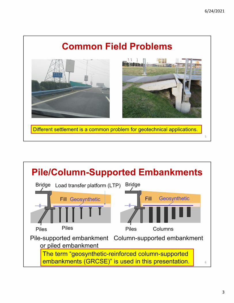
Common Field Problems
Different settlement is a common problem for geotechnical applications.5
Bridge
Piles
Fill
Columns
Bridge
Piles
Fill
Piles
Load transfer platform (LTP)
Pile/Column-Supported Embankments
Pile-supported embankmentor piled embankment
Column-supported embankment
Basal reinforced Geosynthetic-reinforced
Geosynthetic Geosynthetic
The term “geosynthetic-reinforced column-supported embankments (GRCSE)” is used in this presentation. 6

6/24/2021
4
Column-Supported EmbankmentsCourtesy of Mr. C. Dumas
7
Type of Column
Credit: D. Alexiew
Credit: J. Collin
This presentation is mostly based on rigid columns. 8

6/24/2021
5
Common Applications
Reid et al. (1993)
Bridge
Concrete PilePiles
GeosyntheticFill
Soft soil
ExistingNew
ColumnGeosynthetic
Han & Akins (2002)
Tsukada et al. (1993)
Soft soil
GeosyntheticPavement
Subgrade
Column
CenterlineStorage tank
Firm soil
VCCSoft organicsilt & peat
GeosyntheticsRingwallfooting
ASCE G-I (1997)
grouted column
Geosyntheticreinforcedplatform
Uniaxial geogrids
Traffic loading
Soft soil
Alzamora et al. (2000)
Uncontrolled fill
Firm soil
Compacted fillPipes
Zhou (2019) 9
Column Coverage
Ac
Column coverage= Ac/A x 100%
0
10
20
30
40
50
60
70
80
0 5 10 15
Cov
erag
e by
pile
(ca
ps)
(%)
Height of embankment (m)
Crushed stone fillGravel fillRecent projects
Constructed geosynthetic reinforced column-supported embankments
Guidelines for conventional pile supported embankments
(Rathmayer, 1975)
Modified from Han and Gabr (2002)10

6/24/2021
6
Contributions of Geosynthetics
Tensile resistance:- Reduce lateral thrust on columns
Tensioned membrane:- Reduce differential settlement- Transfer load onto columns- Minimize downdrag force- Stabilize soil arch
Columns
Reversely tensioned membrane:- Prevent soil yielding above columns
Tensile anchorage:- Stabilize slope
Columns
Stiffened platform:- Include all the above contributions
Lateral restraint:- Minimize lateral soil movement
Columns
Column
11
Mechanisms and Mechanics
12

6/24/2021
7
Load Transfer Mechanisms
= ps/(H+q0)Soil arching ratio
Critical height HcrStress concentration ratio n = c/s
SRR = s/(H+q0)Stress reduction ratio
Modified from Han (1999)
W ps
H
sc
THcr
Column
Fill
GeosyntheticReinforcement(GR)
q0
dd
Soil arching
Tensioned membrane
Column-soil interaction
Column modulus effect
13
Mechanisms
Progressive Development of Soil Arching
Han, Wang, Al-Naddaf, Xu (2017)
H
B
q
v
1
2
3
Normalized displacement,
Soi
l arc
hing
rat
io,
Initialarching
Maximumarching Stress recovery
Ultimatestate
min
min
ult
ult
Simplified
1.0
10%B
Terzaghi’ssolution
Iglesia et al. (1999)
(1.5%-5%)B
Plane-straincondition
1
2
3
4
0
This curve is called “Ground Reaction Curve (GRC)”.
14
6/24/2021
8
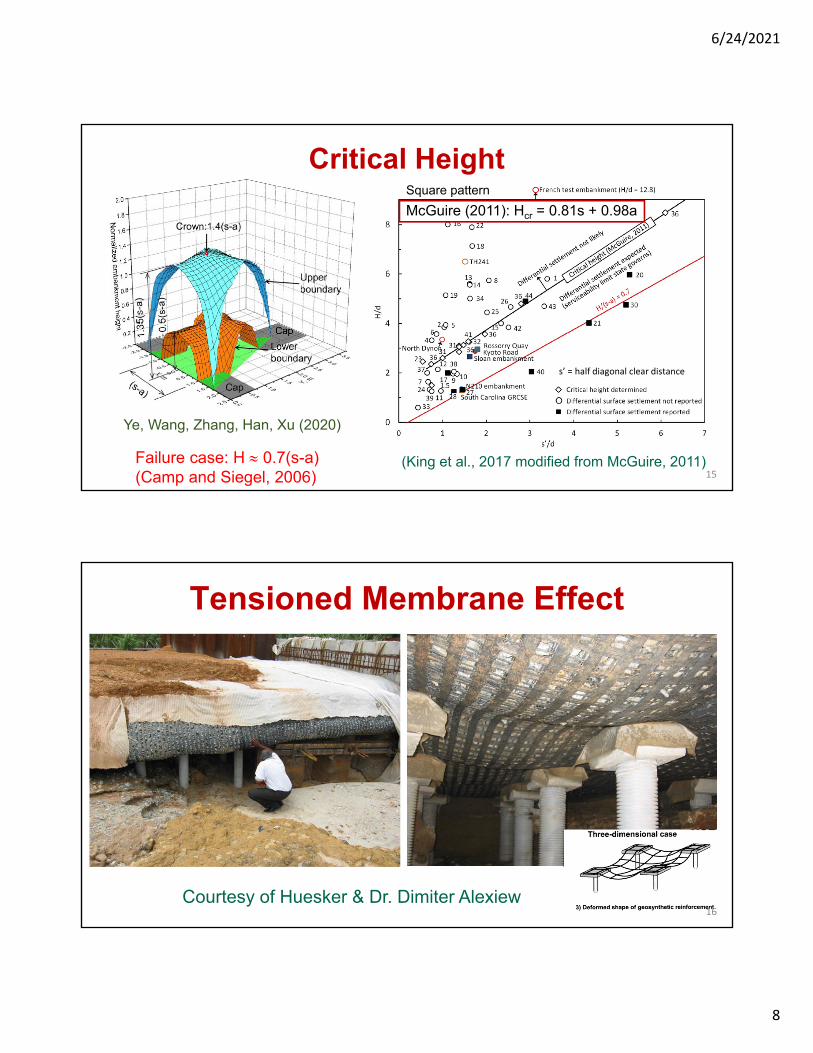
Ye, Wang, Zhang, Han, Xu (2020)
Failure case: H 0.7(s-a)(Camp and Siegel, 2006)
(King et al., 2017 modified from McGuire, 2011)
Critical Height
s’ = half diagonal clear distance
15
McGuire (2011): Hcr = 0.81s + 0.98a
Square pattern
Tensioned Membrane Effect
Courtesy of Huesker & Dr. Dimiter Alexiew16

6/24/2021
9
Column Shape & Pattern Effect2.05% 1.13%
1.78% 0.97%Zhang, Wang, Ye, Han (2019) 17
Strainstrips
Circular columns with triangular pattern induce lowest tensile strain and strain strips should be used for calculation of GR strains.
Monitored Axial Loads in ColumnsChow, Han, Reuter (2020)
s
P
z
Neutralplane
= 0
18

6/24/2021
10
Theoretical Solutions
19
Existing Soil Arching Models
Terzaghi (1943) Carlsson (1987)Hewlett & Randolph (1988)
Yielding
Adapted TerzaghiRussell et al. (2003)*Sloan (2011)* Filz et al. (2019)*FHWA method*
Guido CollinJenner-BushSwedish MethodFHWA beam methodJapanese method
BSI method (2010)Abusharar et al. (2009)Zhuang & Cui (2014)
Chen, Chen, Han, Xu (2008)*
*consider column-soil interaction and load-displacement compatibility 20

6/24/2021
11
Existing Soil Arching Models
Van Eekelen et al. (2013)Zaeske (2001) and
Kempfert et al. (2004)
Germany method - EBGEO Dutch method - CUR 226 (2016)- Concentric arch model
21
Calculated Stresses by Methods
Modified from McGuire & Filz (2008)
Van Eekelen et al.
(K = 1.0)
(K = 0.5)
22
H
s = 2.5 m
a = 1.0 m
= 19 kN/m3, = 35o
Square pattern
GR ps
The main reason for the calculation differences is that the soil arching models were developed at different arching stages.

6/24/2021
12
Proposed GRC for Arching
Displacement, /(s-a)
0.025 0.1
Determined by the adapted Terzaghi method
Determined by the concentric soil arch method
Normalized stress, /(H+q0)
1.0
Modified from Han, Wang, Al-Naddaf, Xu (2017)23
Design Procedure
24

6/24/2021
13
Design Procedure: Step 1
H
q0
, J
L
a
s
, , e0,Cc, Cr
McGuire (2011): Hcr = 0.81s + 0.98a (square pattern)25
Design Procedure: Step 2
Average displacement,
Stress,
H+q0
0.1(s-a)
Subsoil settlement
Subsoil support
'0'
0 0
log1
c z avs
z
C z
e
26
Stress on subsoil av

6/24/2021
14
Design Procedure: Step 3
Average displacement, 0.025(s-a) 0.1(s-a)
Determined by the adapted Terzaghi method
Determined by the concentric soil arch method
Soil arching
Stress,
H+q0
27
Design Procedure: Step 4
Average displacement, 0.1(s-a)
Geosynthetic support
3
4
64
3
g gs
J
s a
Stress,
H+q0
Average net applied stress above geosynthetic
28
Net stress above geosynthetic, Δs

6/24/2021
15
Design Procedure: Step 5
Average displacement, 0.1
Combined support
Combined
SubsoilGeosynthetic
Stress,
H+q0
Subsoil + Geosynthetic
29
Design Procedure: Step 6
Average displacement,
Stress,
0.1
Combined
Calculated
Calculated s
2
2
ss
gs
s a
a s a
22
3
24gs g
g
J s aT
Stress on strips
Tension & strain in strips
H+q0
gg
g
T
J
Determine stress & displacement
ps
30

6/24/2021
16
Case Study 1 – Full-Scale Experiment
Briançon, Simon (2012) and Rowe, Liu (2015)
H = 5 m (16.4 ft), H1 = 0. 55 m (1.8 ft), a = 0.34 m (1.1 ft), s = 2.0 m (6.6 ft), = 19 kN/m3 (121 pcf), = 30o – 36o, Jg = 800 kN/m (55 kips/ft)
CMCSCCG
h (m)
1.5
1.06 ‐ 8
(kN/m3)
19.614.1
20.8
w (%)
3160
31
PI (%)
22
12
(o)30.6
27
c (kPa)
4
1330.6 4
34 020.0
Layer
31
Case Study 1 – Full-Scale Experiment
0102030405060708090
100
0 0.05 0.1 0.15 0.2
Ve
rtic
al s
tres
s (k
Pa)
Differential settlement at embankment base (m)
Soil archingReinforcementSubsoilSubsoil + reinforcement
Measured Calculated
Stress on geosynthetic
55 kPa(8.0 psi)
59 kPa(8.6 psi)
Differential settlementbetween column/soil
41 mm(1.6 in)
43 mm(1.7 in)
Strain ingeotextile (%)
0.2-0.7 0.2-0.4
ps,min = 59 kPa (8.6 psi) (Concentric Arch Model)
ps,ult = 68 kPa (9.9 psi) (Adapted Terzaghi model)
ps,minps,ult
32

6/24/2021
17
Case Study 2 – Woerden Project
Van Eekelen et al. (2020) 33
0.75-m (2.5-ft) thick fill for the working platformcaused excessive subsoil settlement (void)
H = 1.78 m (5.8 ft) a = 0.75 m (2.5 ft)s = 2.24 m (7.3 ft) = 18.3 kN/m3 (116 pcf) = 51o
Jg = 4,717 kN/m (323 kips/ft)
Case Study 2 – Woerden Project
0
10
20
30
40
50
0 0.05 0.1 0.15 0.2
Ve
rtic
al s
tres
s (k
Pa)
Differential settlement at embankment base (m)
Soil arching
Reinforcement
Subsoil
Subsoil + reinf.
Measured Calculated
Stress on geosynthetic
9.4 kPa(1.4 psi)
11.1 kPa(1.6psi)
Differential settlementbetween column/soil
85 mm(3.3 in)
83 mm(3.3 in)
Strain ingeotextile (%)
0.5-0.8 0.8-1.3
ps,min = 8.6 kPa (1.2 psi) (Concentric Arch Model)
ps,ult = 15.0 kPa (2.2 psi) (Adapted Terzaghi model)
ps,min
ps,ult
34

6/24/2021
18
Concluding Remarks Geosynthetic-reinforced column-supported embankments
(GRCSE) are a complex system and have been a hot research topic and increasingly used in the practice in the past 20 years.
Recent research has helped better understand load transfer mechanisms in GRCSE, especially soil arching.
Ground reaction curve is important for describingprogressive development of soil arching with displacement.
A unified design procedure considering progressive development of soil arching, tensioned membrane, subsoil support, and column-soil interaction (downdrag) is proposed, which bridges theory and practice. 35
36
Questions?
Thank you!