20cc dehavilland canada dhc-2 beaver instruction …...©2019 moustache model works, llc 4 20cc...
TRANSCRIPT
20cc DeHavilland Canada
DHC-2 Beaver
Instruction Manual
Version 1.1
©2019 Moustache Model Works, LLC 2
20cc DHC-2 Beaver Instruction Manual
Thank You
Thank you for purchasing the Moustache Model Works 20cc DHC-2 Beaver!
This Beaver was designed using AutoDesk Fusion360, a powerful 3D CAD program, to ensure the best parts fit possible and therefore provide a pleasurable building experience. Drawn directly from the full-scale blueprints, it features about a 99% scale outline. Traditional construction techniques were used to keep the build as simple as possible, while modern laser-cut technology helps to keep everything aligned during construction.
The design intent was to provide a Beaver with a very scale outline, but to keep assembly and setup sim-ple, accessible, and reliable for the vast majority of pilots who will fly this as a sport scale model. To this end, the ailerons, elevator, and rudder use simple CA hinges. The large front hatch provides excellent access to the cockpit for quick battery swaps (electric power version) or for refueling and switch access (gas/glow version). The wing struts connect with simple clevises.
Dimensions and Specfications
Required to Complete
Electric Power System
E-flite Power 60, 400Kv (EFLM4060A) Prop Adapter: Power 46/52/60 (EFLM1934) 60A+ ESC, Castle Creations Talon 90 recommended (CSE010009700) 5000mAh 6S 22.2V 30C LiPo Battery
Connectors w/5mm bullets (suggest XT90 or IC5) 16 x 8E Propeller (suggest APC16080E) 1 inch Spinner Nut 8mm x 1.25mm: P-47D-1 60 (HAN279011)
Gas (Petrol) Power System
DLE-20, DLE-20RA (DLEG0020 or DLEG0420) or equivalent Sullivan 10 oz. Slant Fuel Tank (SUL440), requires Sullivan Gasoline Conversion Kit (SUL484) Propeller (suggest APC 16 x 6, APC16060) Ignition battery and switch, OR Tech-Aero iBEC (http://www.tech-aero.net/ultra-ibec)
Radio Equipment 2 x Standard size servos, 75+ oz-in torque (prototypes used Spektrum A6150) 4-5 Mini servos, 60+ oz-in torque (prototypes used both Hitec HS-5245MG and Spektrum A5060) 6-channel receiver, minimum
6-channel computer transmitter with flap-elev mixing, aileron-rudder mixing, and differential aileron throw strongly recommended
4 x 18-inch (45cm) servo extensions
1 x Y-harness
2 x 12-inch to 18-inch (30-45cm) servo extensions, depending on length of the Y-harness)
Although mini servos are recommended for the flaps, ailerons, and throttle, standard servos may be used.
Wingspan: 91.4 in (2.32m)
Length: 57.6 in (1.46m)
Height: 16 in (406mm)
Weight: 12 - 13 lb (5 - 5.7 kg)
Wing Area: 904 in2 (58.3 dm2)
Airfoil: NACA 4415
Scale: 1/6.3

©2019 Moustache Model Works, LLC 3
20cc DHC-2 Beaver Instruction Manual
Required to Complete (continued) Wheels: Standard size is 3 3/4” dia (95-100mm) with 5mm axle hole
Tundra size is 4 1/2” - 5 1/2” dia (115-140mm) with 5mm axle hole
5mm Wheel Collars x 4
Battery strap, hook-and-loop (Velcro), 12”-15” long (30-38cm) (used for either battery or fuel tank) Hook-and-Loop material for battery mounting
Sponge rubber, 1/4”-1/2” thick (6mm-13mm) for isolating fuel tank
1/8” (3mm) Black heat shrink tubing, 2” long (50mm) for door handles
Adhesives
4-6, 1-oz bottles of medium CA
1, 1-oz bottle of thin CA
1 can CA accelerator 5-15 minute epoxy
30 minute epoxy
Blue thread lock
Epoxy finishing resin (for gas or glow engines only) Milled fiber (available from BVM, item number PA-SR-1905) Microballoons (Top Flite TOPR1090 or Deluxe Materials DLMBD15) Liquid cement for plastic models (TES3507AT)
4 Rolls covering material (6’ or 2m rolls) Spray Paint (suggest Krylon primer and paint for most applications) Craft paint for interior of fuselage,
Options
Besides the choice of power system, the Beaver offers two primary ways to customize your model. First, you may choose either the upper carb intake or the lower carb intake (chin scoop). The chin scoop was used on the earlier airplanes, but most Beavers we see today use the upper carb intake. Second, we have provided both round and rectangular windows for the aft fuselage. You may choose to use one round, one rectangular, or two rectangular windows per side, depending on the aircraft you choose to model. If you choose a single rear window, the aft window bay is simply covered with the covering materi-al. If you choose the rectangular window(s), the pre-cut forward window bay will need to separated from the fuselage side to accommodate.
Building Notes
The 20cc Beaver was designed to minimize the need for plans during construction. The tail surfaces and fuselage can be built on a flat surface, separate from the plans. The wings are built over the plans simply to aid in placing the lower cap strips and the sheeting. NOTE: IF THE WOOD PARTS DO NOT MATCH THE PLANS, BELIEVE THE WOOD! Paper plans can stretch and shrink considerably with humidity and temperature variations, but wood is much more stable.
Use medium CA for most of the assembly. When gluing lite-ply parts, note that the lite-ply is VERY THIRSTY, meaning it will suck-up and absorb a large amount of glue, especially on the edges. To ensure the integrity of your glue joints, apply a coat of glue to the edge, wait about 30 seconds for it to soak in, then apply more glue. Keep doing this until the medium CA stops soaking into the wood, then press the parts together to complete the joint. Usually 2-3 coats are sufficient. For best strength, try to minimize your use of CA accelerator.
The recommended build order is tail surfaces, wings, fuselage. It’s helpful to have the wings done when you fit the windshield hatch in place, and it helps to have the horizontal tail done when you glue the aft fu-selage together. There are many small details, however, especially as you’re completing final assembly, that do not need to be completed in any particular order.
©2019 Moustache Model Works, LLC 4
20cc DHC-2 Beaver Instruction Manual
Building Notes (continued) You will notice the manual shows several lightening holes in the flaps, ailerons, elevator, rudder, and fuse-lage top. These were tried in the second prototype, which was used for creating this manual. After com-pletion, we decided the weight savings was not enough to warrant the potential reduction in scale appear-ance, so they were removed for production.
Floats are probably the most important option for any DHC-2 Beaver. As of this writing (January 2019), the floats for this airplane have not been developed, but the float mounts have been incorporated into the build. These mounts are not accessible after the airplane is built, so make sure you install them during construction if you have any interest in installing floats once they are available.
Several exterior parts will require painting: the cowl, windshield hatch, optional upper carb intake, oil cool-er, landing gear fairings, and possibly the tail cone and rudder fairing. If using a gas (petrol) or electric power system, we have found Krylon brand spray paints to be easy to use and quite durable. If you need a specific paint match and have spray equipment available, common latex paint from the local big-box home improvement store works well, is available in sample sizes, and can be matched to any covering you bring to the store. In this case, it’s good to use a clear coat, again such as Krylon, although we’ve had mixed results spraying Krylon (which is acrylic) over latex. If you’re using a glow engine, Wings West makes some fantastic paint that perfectly matches both MonoKote and Ultracote, but it requires clear coat to be fuel proof.
If using a gasoline engine, the electrical power system can be simplified by using an ignition battery elimi-nator circuit or iBEC. This simple component enables a single battery to power both the radio system and the ignition, while also providing a transmitter-switched ignition kill. If HV-capable servos are used, a sin-gle 2S Li-Po battery can provide all the power required, thus saving weight and complexity.
Due to variations in hardware, it’s possible that the included blind nuts may not fit perfectly into the laser-cut holes of some wooden parts. If this happens, simply drill out the holes to fit.
Recommended Tools
FLAT building surface, T-pins
Sanding block(s) - next to a flat surface, probably the most important tool in the shop. We use a piece of 1/2” - 3/4” plywood cut to 3” x 11” to accept 1/3 of a sheet of sandpaper. Use a good-quality ceramic abra-sive and apply 120 grit on one side and 80 grit on the other using contact cement like 3M77.
Hobby knife with No. 11 blades (buy in bulk, part number EXL22611A) Rotary tool (Dremel) with sanding drum, cutoff wheel Electric drill and drill bits
Allen wrenches, both SAE and metric
Slotted and Philips screwdriver sets, several sizes
Pliers, regular and needle-nose
Adjustable wrench
Razor plane or buck knife
Steel rule
Wax paper Fine-point permanent marker Soldering iron/gun (for soldering connectors if using an electric power system) 4 1/2” Tapered palette knife (recommended for mixing and applying epoxy)
Limit of Liability
Responsibility for safe assembly and operation of this kit depends entirely upon the builder and operator. As Mous-tache Model Works, LLC has no control over the assembly, setup, modification, use, or misuse of this product, no liability shall be assumed nor accepted for any resulting damage or injury caused by its use or misuse.
©2019 Moustache Model Works, LLC 5
20cc DHC-2 Beaver Instruction Manual
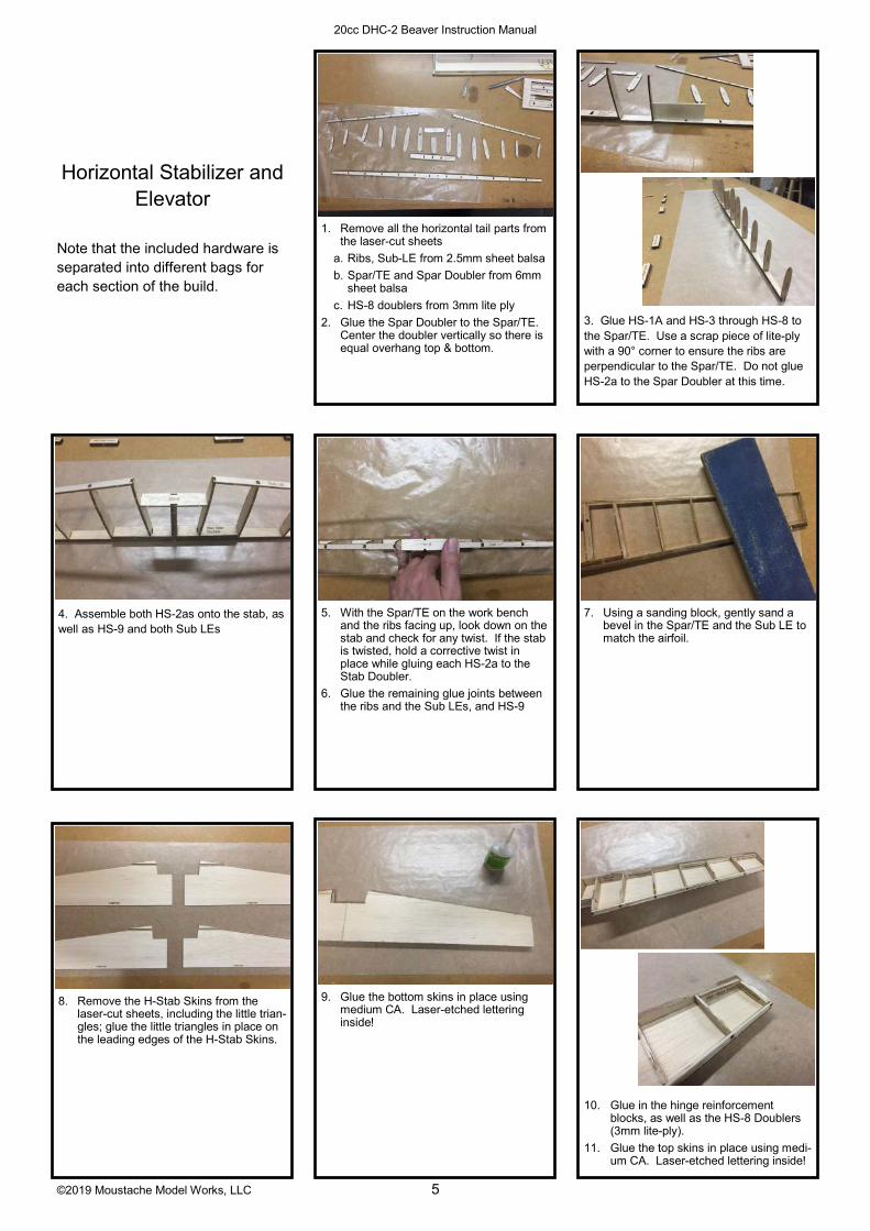
1. Remove all the horizontal tail parts from the laser-cut sheets
a. Ribs, Sub-LE from 2.5mm sheet balsa
b. Spar/TE and Spar Doubler from 6mm sheet balsa
c. HS-8 doublers from 3mm lite ply
2. Glue the Spar Doubler to the Spar/TE. Center the doubler vertically so there is equal overhang top & bottom.
3. Glue HS-1A and HS-3 through HS-8 to the Spar/TE. Use a scrap piece of lite-ply with a 90° corner to ensure the ribs are perpendicular to the Spar/TE. Do not glue HS-2a to the Spar Doubler at this time.
4. Assemble both HS-2as onto the stab, as well as HS-9 and both Sub LEs
9. Glue the bottom skins in place using medium CA. Laser-etched lettering inside!
5. With the Spar/TE on the work bench and the ribs facing up, look down on the stab and check for any twist. If the stab is twisted, hold a corrective twist in place while gluing each HS-2a to the Stab Doubler.
6. Glue the remaining glue joints between the ribs and the Sub LEs, and HS-9
10. Glue in the hinge reinforcement blocks, as well as the HS-8 Doublers (3mm lite-ply).
11. Glue the top skins in place using medi-um CA. Laser-etched lettering inside!
7. Using a sanding block, gently sand a bevel in the Spar/TE and the Sub LE to match the airfoil.
8. Remove the H-Stab Skins from the laser-cut sheets, including the little trian-gles; glue the little triangles in place on the leading edges of the H-Stab Skins.
Horizontal Stabilizer and Elevator
Note that the included hardware is separated into different bags for each section of the build.

©2019 Moustache Model Works, LLC 6
20cc DHC-2 Beaver Instruction Manual
13. Cut two 12 1/8” lengths from the 6mm x 10mm balsa stick
14. Glue in place on the leading edges
15. Carve & sand to airfoil shape
16. Glue the spacers in place against both HS-2as
20. Glue E-8 and E-7 onto the Stab Tip Cores
17. Remove all the elevator parts from the laser-cut sheets
a. Ribs from 2.5mm sheet balsa sheet 10/10
b. LE, joiner supports and hinge sup-ports from 6mm balsa sheet
c. Stab Tip Cores and the E-8s from the 1mm ply sheet
21. Remove the Elevator Skins from the 1.5mm sheet balsa
22. Glue the LE/rib assemblies to the bot-tom Elevator Skins. Make sure the laser etching on the skins is on the inside surface. Use the stab tip as-semblies to aid positioning.
18. Glue the ribs E-1 through E-6 to the leading edges. Take care to center the ribs vertically on the LE. As you did on the horizontal stabilizer, use a scrap piece of lite-ply with a 90 degree corner to ensure the ribs are perpendicular to the LE.
12. Trim & sand the sheeting flush with the Sub-LE and all around the perimeter.
19. Using a sanding block, lightly sand the top and bottom of the LE to match the taper of the ribs
23. Place the elevator on the edge of your work bench. Using a sanding block, sand a bevel on the inside surface of the bottom Elevator Skins to match the ribs. The trailing edge of the sheeting needs to be about ½ the thickness of the sheeting or 1/32” at the trailing edge.

©2019 Moustache Model Works, LLC 7
20cc DHC-2 Beaver Instruction Manual
26. Glue on the top Elevator Skins.
27. Glue the upper & lower tip blocks, then carve & sand to shape.
27. Sanding to shape. Use some masking tape to avoid sanding into the elevator sheeting while using coarse sandpa-per at first.
32. Glue the elevator joiner in place using epoxy on the mounting tab. Take care not to get glue on the wire.
33. Glue the beavertail in place over the joiner. Take care not to get glue on the wire.
28. Glue both HS-2b and HS-1b to the low-er beavertail skin.
34. On the leading edge of the elevators, mark and drill the location of the eleva-tor joiner. To do this, hold the eleva-tors in place against the horizontal stabilizer and use a piece of scrap 2.5mm balsa as a spacer between the tip of the stabilizer and the inside edge of the elevator counter-balance. Mark the location, then drill in straight with a 1/8” bit.
29. Cut a relief groove in the trailing edge of the horizontal stab to provide clearance for the elevator control horn. Also cut a bevel in the slot for the joiner mounting tab so it seats up against the trailing edge.
24. Glue in the elevator joiner supports and the hinge supports.
25. Glue in the tip assemblies.
30. Bevel the trailing edge of the lower bea-vertail skin as you did with the eleva-tors.
31. Glue the upper beavertail skin in place.
35. Using a hobby knife, cut a notch from that hole to the inboard end of the elevator. Cut a radius in that notch to accommodate the radius in the bend of the elevator joiner.
©2019 Moustache Model Works, LLC 8
20cc DHC-2 Beaver Instruction Manual
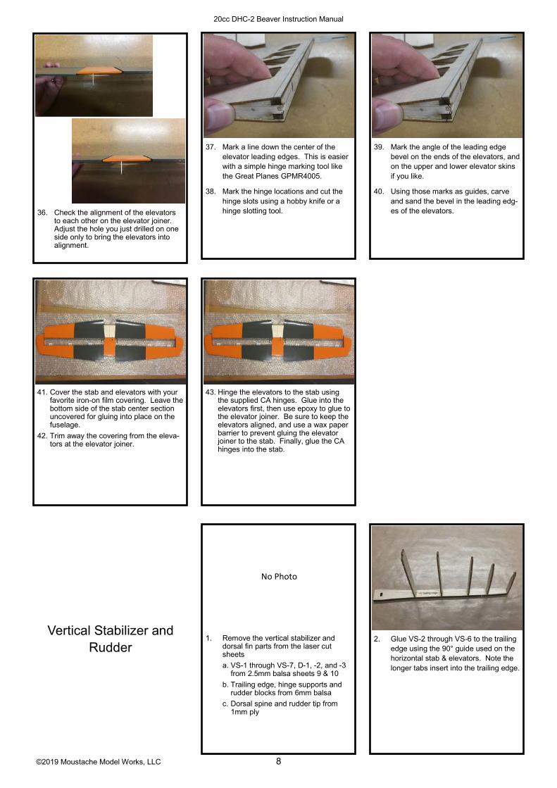
37. Mark a line down the center of the elevator leading edges. This is easier with a simple hinge marking tool like the Great Planes GPMR4005.
38. Mark the hinge locations and cut the hinge slots using a hobby knife or a hinge slotting tool.
39. Mark the angle of the leading edge bevel on the ends of the elevators, and on the upper and lower elevator skins if you like.
40. Using those marks as guides, carve and sand the bevel in the leading edg-es of the elevators.
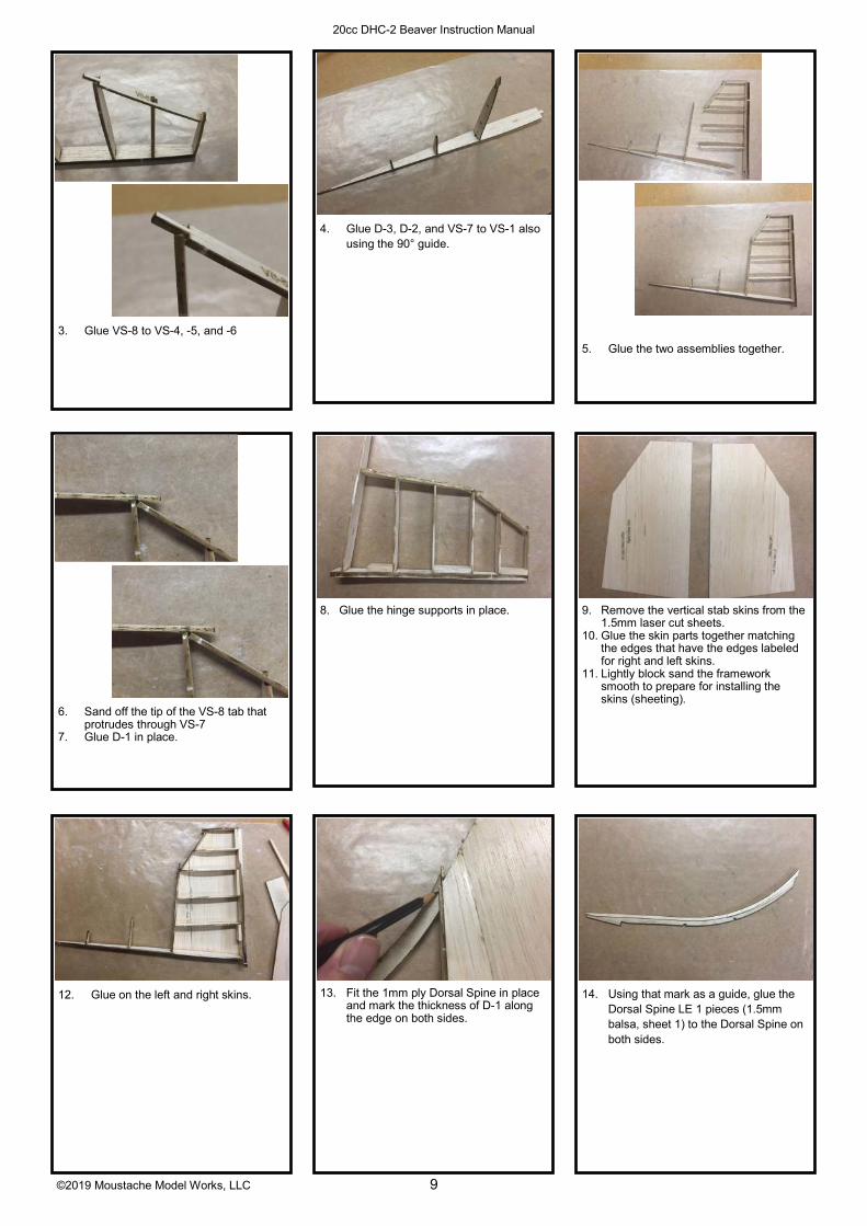
41. Cover the stab and elevators with your favorite iron-on film covering. Leave the bottom side of the stab center section uncovered for gluing into place on the fuselage.
42. Trim away the covering from the eleva-tors at the elevator joiner.
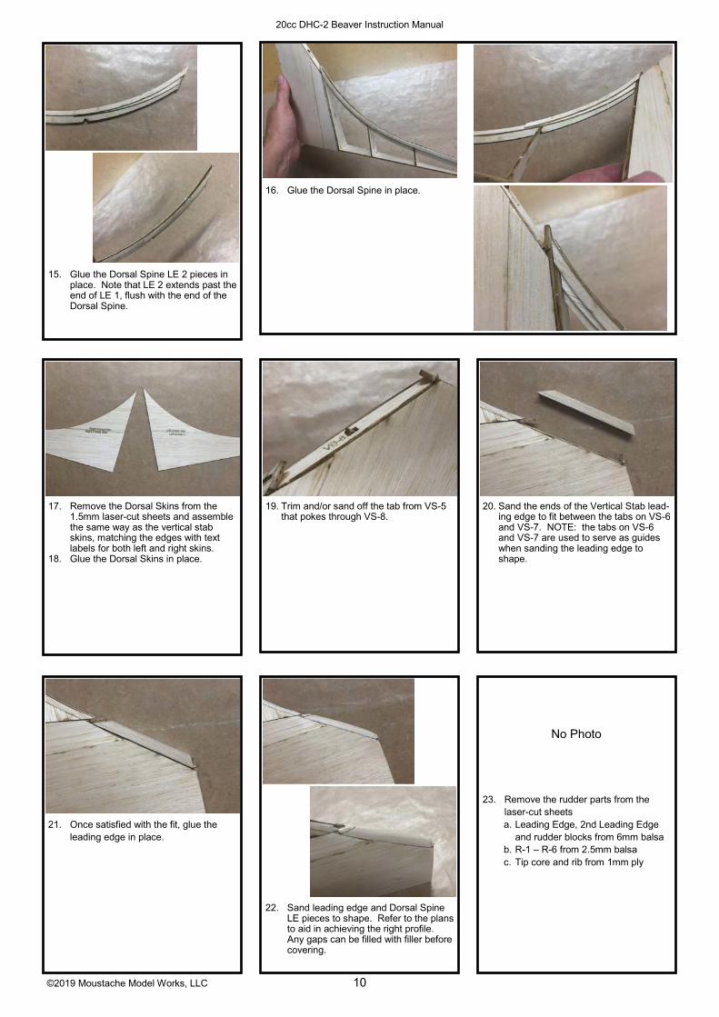
1. Remove the vertical stabilizer and dorsal fin parts from the laser cut sheets
a. VS-1 through VS-7, D-1, -2, and -3 from 2.5mm balsa sheets 9 & 10
b. Trailing edge, hinge supports and rudder blocks from 6mm balsa
c. Dorsal spine and rudder tip from 1mm ply
43. Hinge the elevators to the stab using the supplied CA hinges. Glue into the elevators first, then use epoxy to glue to the elevator joiner. Be sure to keep the elevators aligned, and use a wax paper barrier to prevent gluing the elevator joiner to the stab. Finally, glue the CA hinges into the stab.
36. Check the alignment of the elevators to each other on the elevator joiner. Adjust the hole you just drilled on one side only to bring the elevators into alignment.
2. Glue VS-2 through VS-6 to the trailing edge using the 90° guide used on the horizontal stab & elevators. Note the longer tabs insert into the trailing edge.
Vertical Stabilizer and Rudder
No Photo
©2019 Moustache Model Works, LLC 9
20cc DHC-2 Beaver Instruction Manual
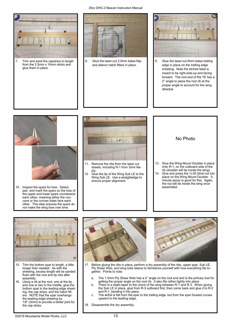
4. Glue D-3, D-2, and VS-7 to VS-1 also using the 90° guide.
5. Glue the two assemblies together.
13. Fit the 1mm ply Dorsal Spine in place and mark the thickness of D-1 along the edge on both sides.
8. Glue the hinge supports in place.
3. Glue VS-8 to VS-4, -5, and -6
14. Using that mark as a guide, glue the Dorsal Spine LE 1 pieces (1.5mm balsa, sheet 1) to the Dorsal Spine on both sides.
6. Sand off the tip of the VS-8 tab that protrudes through VS-7
7. Glue D-1 in place.
9. Remove the vertical stab skins from the 1.5mm laser cut sheets.
10. Glue the skin parts together matching the edges that have the edges labeled for right and left skins.
11. Lightly block sand the framework smooth to prepare for installing the skins (sheeting).
12. Glue on the left and right skins.
©2019 Moustache Model Works, LLC 10
20cc DHC-2 Beaver Instruction Manual
16. Glue the Dorsal Spine in place.
22. Sand leading edge and Dorsal Spine LE pieces to shape. Refer to the plans to aid in achieving the right profile. Any gaps can be filled with filler before covering.
19. Trim and/or sand off the tab from VS-5 that pokes through VS-8.
23. Remove the rudder parts from the laser-cut sheets
a. Leading Edge, 2nd Leading Edge and rudder blocks from 6mm balsa
b. R-1 – R-6 from 2.5mm balsa
c. Tip core and rib from 1mm ply
17. Remove the Dorsal Skins from the 1.5mm laser-cut sheets and assemble the same way as the vertical stab skins, matching the edges with text labels for both left and right skins.
18. Glue the Dorsal Skins in place.
20. Sand the ends of the Vertical Stab lead-ing edge to fit between the tabs on VS-6 and VS-7. NOTE: the tabs on VS-6 and VS-7 are used to serve as guides when sanding the leading edge to shape.
21. Once satisfied with the fit, glue the leading edge in place.
15. Glue the Dorsal Spine LE 2 pieces in place. Note that LE 2 extends past the end of LE 1, flush with the end of the Dorsal Spine.
No Photo

©2019 Moustache Model Works, LLC 11
20cc DHC-2 Beaver Instruction Manual
25. Assemble R-6 and the plywood rib to the Rudder Tip Core.
32. Glue in the rudder block pieces, the rudder torque rod support blocks.
33. As done on the elevators, sand a bev-el in the trailing edge of the skin to match the ribs.
34. Glue on the second rudder skin, matching the other skin at the trailing edge.
35. Glue on the left and right rudder tip blocks.
27. Using the vertical stabilizer as a guide, now glue the tip assembly to the rud-der leading edges. Be careful not to glue the rudder to the vertical stabi-lizer.
28. Lightly block sand the framework smooth to prepare for installing the skins (sheeting).
29. Remove the rudder skins from the 1.5mm balsa laser cut sheets.
30. Glue the skin parts together matching the edges that have the edges labeled for right and left skins.
31. Note skin alignment to 2nd leading edge.
31. Glue one side of the rudder skin in place. Use the tip plywood rib as a guide; match the trailing edge of the skin to the trailing edge of the tip core. Note the leading edge of the skin is not straight: the leading edge of the skin at the tip will rest about 1/8” aft of the edge of the 2nd Leading Edge, while the lower front corner of the skin falls about ¼” aft of the same edge. (see photos in next box)
24. Glue the ribs to the Leading edge using the 90° guide.
No Photo
26. Glue the 2nd Leading Edge to the Leading Edge using the tip assembly as a guide. Be careful not to glue the tip assembly in at this time.
No Photo

©2019 Moustache Model Works, LLC 12
20cc DHC-2 Beaver Instruction Manual
37. Carve & sand the bevel on the rudder leading edge.
39. Cover the fin and rudder with your favorite covering film.
40. Trim the covering away from the rud-der where the torque rod attaches, then glue the torque rod into place.
41. Hinge the rudder to the fin using the supplied CA hinges.
36. Carve and sand the tips to shape. Note the tip radius transitions to a flat trailing edge where the tip cores meet the skins at the trailing edge.
38. Drill a 1/8” hole (3mm) for the rudder torque rod, 5/16” (8mm) from the bot-tom of the rudder. Cut a groove from that hole to the root to allow the torque rod to nest into the rudder leading edge. Cut or file a radius between the hole and the groove to get a better fit.
Wings
1. Lay the plans on the building board and cover with wax paper.
2. Lay the leading edge sheeting (2.5mm x 3” x 48”) in place over the plan and pin in place. Do not trim the LE sheeting to width at this time.
3. Do the same with the trailing edge sheeting (2.5mm x 3/4” x 48”).
4. Cut a piece 9 3/4” (248mm) long from the 2.5mm x 4” x 48” sheet for the cen-ter section sheeting (root end of the wing), then trim it to 3 3/4” wide (95mm). Glue and pin in place to the leading edge and trailing edge sheeting.
5. Use the laser-cut, 6mm thick trailing edge to determine where to trim the LE & TE sheeting to length. It should be close to 39 1/8” in length. Since paper plans are more subject to distor-tion over time due to heat and humidity changes, we prefer using the wood trailing edge to determine the proper length. Also, we prefer to trim the sheeting a little long at this time and sand flush on both ends after the wing is removed from the building board.
6. Again using the laser-cut trailing edge, mark the center location of the cap strips on the leading edge and trailing edge sheeting.
©2019 Moustache Model Works, LLC 13
20cc DHC-2 Beaver Instruction Manual
8. Glue the laser-cut 2.5mm balsa flap and aileron hatch fillers in place.
11. Remove the ribs from the laser cut sheets, including R-1 from 3mm lite-
ply. 12. Glue the tip of the Wing Sub LE to the
Wing Sub LE. Use a straightedge to ensure proper alignment.
7. Trim and sand the capstrips to length from the 2.5mm x 10mm sticks and glue them in place.
9. Glue the laser-cut 6mm balsa trailing edge in place on the trailing edge sheeting. Note the etched label is meant to be right-side-up and facing forward. The root end of the TE has a 2° angle to place the root rib at the proper angle to account for the wing dihedral.
13. Glue the Wing Mount Doubler in place onto R-1, on the outboard side of the rib (doubler will be inside the wing).
14. Glue and press the ¼-20 blind nut into place on the Wing Mount Doubler. 5-
minute epoxy is good for this. Again, the nut will be inside the wing once assembled.
15. Trim the bottom spar to length, a little longer than needed. As with the sheeting, excess length will be sanded flush with the root and tip ribs after assembly.
16. Using a rib at the root, one at the tip, and one or two in the middle, glue the bottom spar to the leading edge sheet-ing, the cap strips, and the hatch fill-ers. NOTE that the spar overhangs the leading edge sheeting by 1/8” (3mm) to provide a better joint for the cap strips.
17. Before gluing the ribs in place, perform a dry assembly of the ribs, upper spar, Sub LE, Ply Shear Web, and wing tube sleeve to familiarize yourself with how everything fits to-gether. Points to note:
a. The 1.5mm Ply Shear Web has a 2° angle on the root end and is the primary tool for getting the proper angle on the root rib. It also fits rather tightly into place.
b. There is a slight taper to the chord of the wing between R-1 and R-3. When gluing the Sub LE in place, glue from R-3 outboard first, then come back and glue it to R-2 and R-1, bending it into place.
c. The airfoil is flat from the spar to the trailing edge, but from the spar forward curves upward to the leading edge.
18. Disassemble the dry assembly.
10. Inspect the spars for bow. Select, pair, and mark the spars so the bow of the upper and lower spars counteracts each other, meaning either the con-cave or the convex sides face each other. This step ensures the spars do not make the wing bow over time.
No Photo

©2019 Moustache Model Works, LLC 14
20cc DHC-2 Beaver Instruction Manual
20. Glue the Ply Shear Web in place against the aft edge of the bottom spar.
21. Glue rib R-1 in place, making sure it’s firmly against the Ply Shear Web to establish the proper angle.
24. Before gluing the Sub LE in place, sand a slight bevel into the bottom edge to match the contour of the ribs. This bevel will enable the bottom sheeting to glue properly into place. Once the bevel is done, glue the Sub LE in place.
19. Glue all ribs from R-2 outboard into place from the spar to the trailing edge. Use the Ply Shear Web as a tool to keep ribs R-2 – R-5 aligned properly.
22. Glue the upper spar in place. The most important joint in this step is where the spar glues to the Ply Shear Web, so use sufficient glue to ensure a solid joint here.
25. Fit the 1.5mm ply flap hatch liner in place. The narrow edge goes forward against the spar. Don’t glue in place until you test the fit the wing tube sleeve in place. If the wing tube sleeve won’t slide in over the top of the hatch liner, then sand a slight relief in the hatch liner using a sanding drum on a rotary tool. Glue the flap hatch liner in place.
26. Glue the aileron hatch liner in place, narrow edge forward.
27. Glue the shear webs in place (1.5mm laser-cut balsa). Note the shear webs at the flap and aileron servo bays are slightly shorter to allow for the thick-ness of the hatch liners.
28. Glue the wing tube plug (2.5mm sheet 6) into place inside the wing tube sleeve (9 5/8” length), flush with the end. We suggest 5 min epoxy for this over CA, since cardboard tends to absorb CA so much.
23. If you have not already done so, trim the upper spar to length.
29. Glue the wing tube sleeve in place using 15-30 min epoxy, mixed with microballoons if you like. The end with the plug should be outboard. Glue securely to all ribs and the Ply Shear Web.
©2019 Moustache Model Works, LLC 15
20cc DHC-2 Beaver Instruction Manual
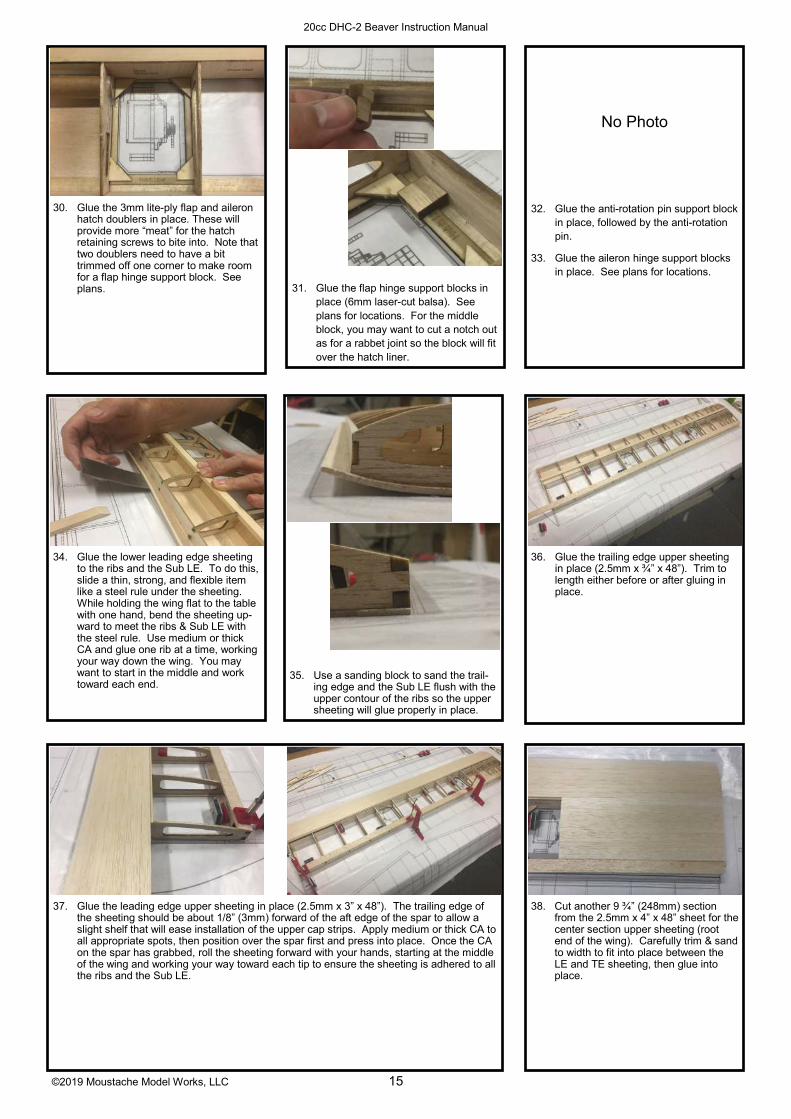
31. Glue the flap hinge support blocks in place (6mm laser-cut balsa). See plans for locations. For the middle block, you may want to cut a notch out as for a rabbet joint so the block will fit over the hatch liner.
35. Use a sanding block to sand the trail-ing edge and the Sub LE flush with the upper contour of the ribs so the upper sheeting will glue properly in place.
30. Glue the 3mm lite-ply flap and aileron hatch doublers in place. These will provide more “meat” for the hatch retaining screws to bite into. Note that two doublers need to have a bit trimmed off one corner to make room for a flap hinge support block. See plans.
32. Glue the anti-rotation pin support block in place, followed by the anti-rotation pin.
33. Glue the aileron hinge support blocks in place. See plans for locations.
36. Glue the trailing edge upper sheeting in place (2.5mm x ¾” x 48”). Trim to length either before or after gluing in place.
37. Glue the leading edge upper sheeting in place (2.5mm x 3” x 48”). The trailing edge of the sheeting should be about 1/8” (3mm) forward of the aft edge of the spar to allow a slight shelf that will ease installation of the upper cap strips. Apply medium or thick CA to all appropriate spots, then position over the spar first and press into place. Once the CA on the spar has grabbed, roll the sheeting forward with your hands, starting at the middle of the wing and working your way toward each tip to ensure the sheeting is adhered to all the ribs and the Sub LE.
34. Glue the lower leading edge sheeting to the ribs and the Sub LE. To do this, slide a thin, strong, and flexible item like a steel rule under the sheeting. While holding the wing flat to the table with one hand, bend the sheeting up-ward to meet the ribs & Sub LE with the steel rule. Use medium or thick CA and glue one rib at a time, working your way down the wing. You may want to start in the middle and work toward each end.
38. Cut another 9 ¾” (248mm) section from the 2.5mm x 4” x 48” sheet for the center section upper sheeting (root end of the wing). Carefully trim & sand to width to fit into place between the LE and TE sheeting, then glue into place.
No Photo

©2019 Moustache Model Works, LLC 16
20cc DHC-2 Beaver Instruction Manual
40. Trim and sand the upper and lower leading edge sheeting flush with the Sub LE. Also sand the sheeting flush with the root and tip ribs at this time.
44. Carve and sand the leading edge to shape as shown on the plans. We find it easiest to do this in two steps. First, carve & sand the top and bottom of the LE to an angle that’s tangent to the top and bottom sheeting. Second, sand to the final shape. The Tip Mount-ing Rib can be used to trace the proper outline onto the ends of the leading edge to help achieve the proper shape.
39. Trim and sand the upper capstrips to length and glue them in place.
41. Trim the leading edge (10mm x 25mm x 48”) to about 39 ½” long.
42. Mark a line on one face of the leading edge 3 ¾” (95mm) from the end of the leading edge. Carefully cut about half to two-thirds of the way through the leading edge on this line using a razor saw. This cut will enable the leading edge to easily bend for the tapered section between ribs R-1 and R-3.
45. Sand the trailing edge lightly to ensure flatness, to remove any overhang from the upper or lower sheeting.
46. Fit the Tip Mounting Rib into the fiberglass wing tip. Sand lightly at the leading and trail-ing edges as required to make the rib fit into the tip. Once satisfied with the fit, glue into place using epoxy.
43. Glue the leading edge in place against the Sub LE and the upper and lower sheeting. The relief cut from the previ-ous step goes inside against the Sub LE at rib R-3. Glue the outboard sec-tion first, then bend the inboard section into place. Trim and sand the ends flush with the root and tip ribs.
47. Glue the wingtip in place using medi-um or thick CA if you’re confident with your positioning skills, or epoxy if you’re not.

©2019 Moustache Model Works, LLC 17
20cc DHC-2 Beaver Instruction Manual
49. Cut a length of the ½” (13mm) triangle stock to 21 5/8” (549mm) and glue in place on the trailing edge of the wing.
52. Assemble the flap and aileron hatches/servo mounts. The hatches are 1.5mm plywood and the servo mounts are 3mm lite ply.
a. Two sizes are provided to accommodate either standard-sized or mini servos.
b. Doublers are included to provide more meat for the servo mounting screws. For mini servos, the doublers fit on the top of the mounts; for standard servos, the doublers fit on the bottom of the mounts.
c. The angle braces fit on both sizes of mount.
d. The orientation of the hatches is marked on the inside of the hatches.
48. Cut a hole in the trailing edge for the flap pushrod. This hole needs to be about ¼” – 5/16” (6-8mm) wide and about 3/8” (9-10mm) tall, located al-most to the upper trailing edge sheet-ing. See plans for spanwise location; on the left wing the hole is centered 10” (254mm) from the root, and on the right wing it’s centered 11 ¾” (298mm) from the root. You may want to wait until the flaps are finished before com-pleting this step.
50. Sand the upper surface of the triangle stock to match the curvature of the upper surface of the wing. You may want to use masking tape to protect the wing while rough sanding.
54. Use the hatches as guides to mark the locations of the hatch retaining screws. Drill pilot holes for the screws using a .050” – 1/16” bit.
51. Drill and file the hole for the flap push-rod into the triangle stock.
53. Glue the 1mm wing hatch spacers into place. These spacers ensure the outer surfaces of the flap and aileron hatches are flush with the wing sur-face.
55. Mount the hatches using 2mm x 10mm button head screws.

©2019 Moustache Model Works, LLC 18
20cc DHC-2 Beaver Instruction Manual
1. Remove all the flap parts from the laser-cut sheets. a. Skins and ribs from 2.5mm balsa
b. Flap horn from 1.5mm ply
c. Leading edge from 6mm balsa
Note: The flap and aileron skins in these photos show lightening holes which were tested in Prototype #2, but were deleted for production.
6. Glue the leading edge into place.
2. Pin or otherwise secure the lower flap skin to the building board.
3. Trim a piece of ¼” (6mm) triangle stock to length and glue into place on the leading edge.
10. Glue the upper skin in place, keeping the flap flat on the building board.
4. Glue the ribs into place. 5. Glue the hinge support blocks into
place at the ends of the flap. Wait until the Flap Horn is installed to install the third support block.
9. Sand the leading edge and trailing edge to match the contour of the ribs. Note that the upper surface of the flap has a slight contour – the upper sur-face is not flat.
11. Carve and sand the leading edge to shape.
Flaps
No Photo
7. Fit and glue the Flap Horn into place. You will have to deepen the slot in the leading edge with a file, hobby knife, or razor saw to get a proper fit.
8. Glue the final hinge support block in place against the Flap Horn.
©2019 Moustache Model Works, LLC 19
20cc DHC-2 Beaver Instruction Manual
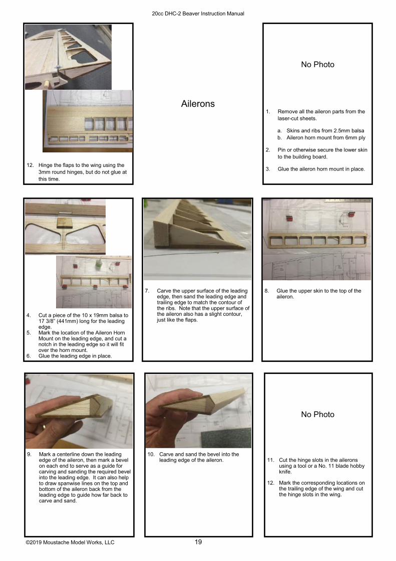
7. Carve the upper surface of the leading edge, then sand the leading edge and trailing edge to match the contour of the ribs. Note that the upper surface of the aileron also has a slight contour, just like the flaps.
1. Remove all the aileron parts from the laser-cut sheets.
a. Skins and ribs from 2.5mm balsa
b. Aileron horn mount from 6mm ply
2. Pin or otherwise secure the lower skin to the building board.
3. Glue the aileron horn mount in place.
10. Carve and sand the bevel into the leading edge of the aileron.
4. Cut a piece of the 10 x 19mm balsa to 17 3/8” (441mm) long for the leading edge.
5. Mark the location of the Aileron Horn Mount on the leading edge, and cut a notch in the leading edge so it will fit over the horn mount.
6. Glue the leading edge in place.
9. Mark a centerline down the leading edge of the aileron, then mark a bevel on each end to serve as a guide for carving and sanding the required bevel into the leading edge. It can also help to draw spanwise lines on the top and bottom of the aileron back from the leading edge to guide how far back to carve and sand.
11. Cut the hinge slots in the ailerons using a tool or a No. 11 blade hobby knife.
12. Mark the corresponding locations on the trailing edge of the wing and cut the hinge slots in the wing.
Ailerons
8. Glue the upper skin to the top of the aileron.
12. Hinge the flaps to the wing using the 3mm round hinges, but do not glue at this time.
No Photo
No Photo

©2019 Moustache Model Works, LLC 20
20cc DHC-2 Beaver Instruction Manual
1. Remove the bulkheads from the 3mm lite ply sheets. Use a hobby knife to cut through the joining tabs holding the parts in the sheets. Also remove Bulk-head 3 from the 6mm ply sheet.
2. Glue the Bulkhead 4 Stiffener in place on the front side of Bulkhead 4, across the top.
Fuselage
3. Attach the float mount and strut mount fittings to the aft sides of bulkheads 2, 2.5, 3, and 4 using 4-40 blind nuts and 4-40 x 3/8” Socket Head Cap Screws. Bulkhead labels face forward, so attach the fittings on the side opposite the etched labels, with the blind nuts on the same side as the labels. NOTE: ONCE THE FUSELAGE IS BUILT, THE FIT-TINGS ON BULKHEADS 2, 2.5, AND 3 WILL BE UNACCESSIBLE. Use epoxy on the blind nuts and threadlock on the cap screws.
4. The blind nuts close to the edge of bulkheads 2.5 and 3 will probably overhang the edge of the bulkheads. Remove the float mounts from these locations, file the blind nuts flush with the edge of the bulkheads, and re-
install the float mounts.
5. Glue the 2.5mm balsa sheeting help-ers to the aft side of Bulkhead 4 (labeled “AFT”) and the forward side of Bulkhead 2 (labeled “FWD”).
6. If installing a DLE-20 engine (not the -RA version), trim the forward end of the floor to the line etched on the top side, and trim the Motor Box Left Side to the line etched on it.
7. On the bottom side of the floor (the side without etching), glue: a. The servo mount doublers (nested
in the servo cutouts in the floor, 3mm lite ply)
b. The landing gear mount (6mm ply) c. The servo cover magnet holders
(3mm lite ply, nested in the servo cover tops)

©2019 Moustache Model Works, LLC 21
20cc DHC-2 Beaver Instruction Manual
8. Glue the 6mm DIA magnets in place in the floor using epoxy. Pay attention to magnet polarity, marking them to keep them sorted. If you make them all the same polarity, then the front and rear covers will be interchangeable.
10. Mount the elevator and rudder servos to the floor. If you don’t want to mount the servos at this time, at least get the servo mounting screw holes drilled now, while the floor is easily accessi-ble.
9. Glue Bulkhead 2.5 to the floor and the landing gear mount. Make sure the float mounts are on the aft side of the bulkhead!
No Photo
11. Glue the aft fuselage tips onto the ends of the fuselage sides, followed by the Stab Mount Doublers.
12. Glue the Fuse Doublers and Fwd Fuse Doublers into place on the fuselage sides. Use Bulkhead 3 to help get them properly positioned.
13. Glue the 1mm ply door frames in place on the fuselage sides.
14. Glue the 1mm ply door stiffeners in place at this time. They are not need-ed for the assembly yet, but since they have been removed from the sheet, installing them now will prevent dam-aging them during storage.
Motor Box Assembly for Electric Power Systems
15. Install the 4mm blind nuts on the back side of the firewall, the side without etching. Glue the blind nuts in place with epoxy. NOTE: The holes provid-ed in the firewall are for an E-flite Pow-er 60 X-mount. If using a different motor, different holes may need to be drilled. The center location of the motor is etched on the front of the firewall to aid in properly locating the motor. Both right and down thrust are accounted for in that location.
16. Place Bulkhead 2 in place along with the left and right motor box sides. Tape Bulkhead 2 in place for now.
©2019 Moustache Model Works, LLC 22
20cc DHC-2 Beaver Instruction Manual
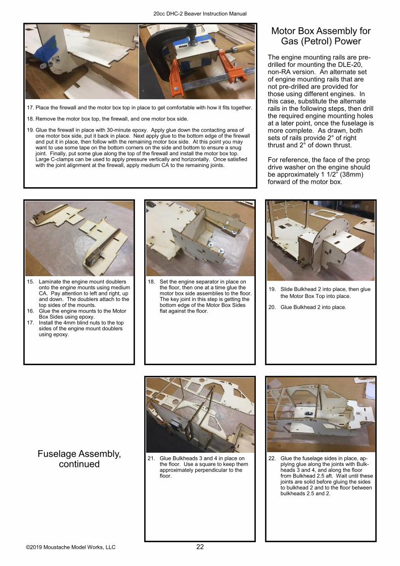
17. Place the firewall and the motor box top in place to get comfortable with how it fits together.
18. Remove the motor box top, the firewall, and one motor box side.
19. Glue the firewall in place with 30-minute epoxy. Apply glue down the contacting area of one motor box side, put it back in place. Next apply glue to the bottom edge of the firewall and put it in place, then follow with the remaining motor box side. At this point you may want to use some tape on the bottom corners on the side and bottom to ensure a snug joint. Finally, put some glue along the top of the firewall and install the motor box top. Large C-clamps can be used to apply pressure vertically and horizontally. Once satisfied with the joint alignment at the firewall, apply medium CA to the remaining joints.
Motor Box Assembly for Gas (Petrol) Power
The engine mounting rails are pre-
drilled for mounting the DLE-20, non-RA version. An alternate set of engine mounting rails that are not pre-drilled are provided for those using different engines. In this case, substitute the alternate rails in the following steps, then drill the required engine mounting holes at a later point, once the fuselage is more complete. As drawn, both sets of rails provide 2° of right thrust and 2° of down thrust.
For reference, the face of the prop drive washer on the engine should be approximately 1 1/2” (38mm) forward of the motor box.
15. Laminate the engine mount doublers onto the engine mounts using medium CA. Pay attention to left and right, up and down. The doublers attach to the top sides of the mounts.
16. Glue the engine mounts to the Motor Box Sides using epoxy.
17. Install the 4mm blind nuts to the top sides of the engine mount doublers using epoxy.
18. Set the engine separator in place on the floor, then one at a time glue the motor box side assemblies to the floor. The key joint in this step is getting the bottom edge of the Motor Box Sides flat against the floor.
19. Slide Bulkhead 2 into place, then glue the Motor Box Top into place.
20. Glue Bulkhead 2 into place.
Fuselage Assembly, continued
21. Glue Bulkheads 3 and 4 in place on the floor. Use a square to keep them approximately perpendicular to the floor.
No Photo
22. Glue the fuselage sides in place, ap-plying glue along the joints with Bulk-heads 3 and 4, and along the floor from Bulkhead 2.5 aft. Wait until these joints are solid before gluing the sides to bulkhead 2 and to the floor between bulkheads 2.5 and 2.

©2019 Moustache Model Works, LLC 23
20cc DHC-2 Beaver Instruction Manual
23. Cut a 7 13/16” (198mm) length of 6mm x 13mm stick and glue in place on the front side of Bulkhead 3.
No Photo
26. Using a sharp hobby knife and a straightedge, score the fuselage sides at the forward edge of Bulkhead 2, where the tabs stick into the sides. You only need to cut about halfway through the outer ply. This step is to make it easier to bend the sides in-ward to attach to the Motor Box Top and to Bulkhead 1.
24. Glue the magnet holders on the back side of the Overhead Bulkhead.
25. Glue the 10mm DIA magnets into place in the Overhead Bulkhead, then glue the Overhead Bulkhead into place.
31. Install the wing tube sleeve. It should be flush to the fuselage sides on both sides.
32. Flip the fuselage upside-down to install the Fuselage Bottom. Apply a small shot of CA accelerator to the circled locations of the bottom sheet before assembly to help the CA “grab” as the sheeting is wrapped around the slightly curved Bulkheads 2.5 and 2.
27. Bend the sides inward and glue to the Motor Box Top. You will hear a slight cracking of the wood as it bends.
30. Install the Cabin Angle Frames.
28. Install Bulkhead 1, etched label for-ward. Note the fuselage sides insert into the long tabs on either side of the bulkhead.
29. Run a bead of either thin or medium CA over the score lines you just made on the fuselage sides for strength.
©2019 Moustache Model Works, LLC 24
20cc DHC-2 Beaver Instruction Manual
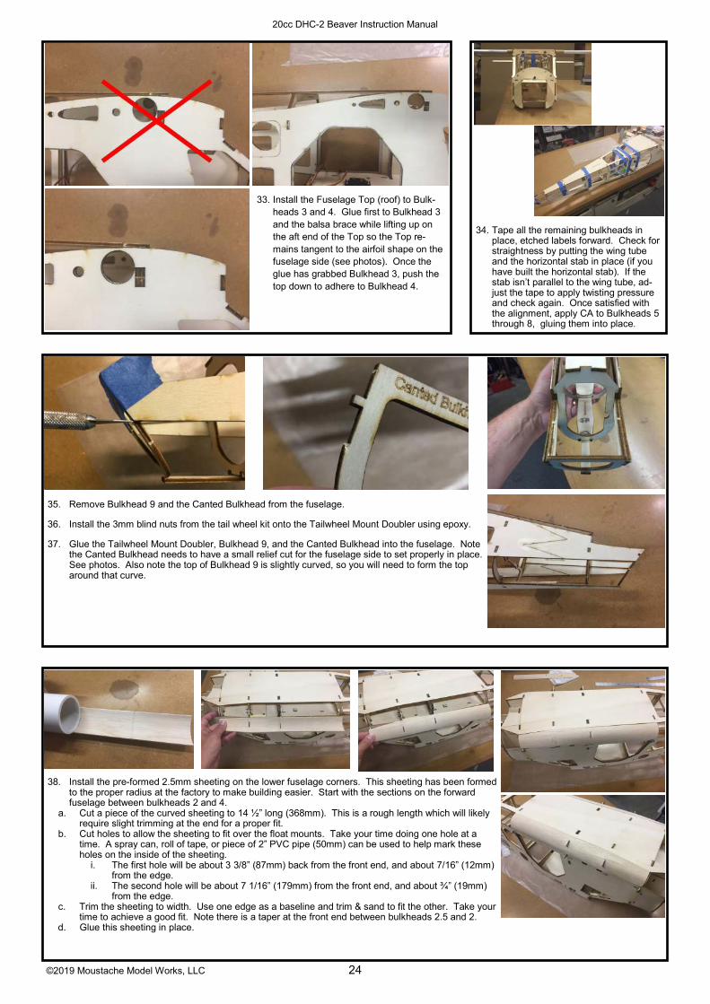
33. Install the Fuselage Top (roof) to Bulk-heads 3 and 4. Glue first to Bulkhead 3 and the balsa brace while lifting up on the aft end of the Top so the Top re-mains tangent to the airfoil shape on the fuselage side (see photos). Once the glue has grabbed Bulkhead 3, push the top down to adhere to Bulkhead 4.
34. Tape all the remaining bulkheads in place, etched labels forward. Check for straightness by putting the wing tube and the horizontal stab in place (if you have built the horizontal stab). If the stab isn’t parallel to the wing tube, ad-just the tape to apply twisting pressure and check again. Once satisfied with the alignment, apply CA to Bulkheads 5 through 8, gluing them into place.
35. Remove Bulkhead 9 and the Canted Bulkhead from the fuselage.
36. Install the 3mm blind nuts from the tail wheel kit onto the Tailwheel Mount Doubler using epoxy.
37. Glue the Tailwheel Mount Doubler, Bulkhead 9, and the Canted Bulkhead into the fuselage. Note the Canted Bulkhead needs to have a small relief cut for the fuselage side to set properly in place. See photos. Also note the top of Bulkhead 9 is slightly curved, so you will need to form the top around that curve.
38. Install the pre-formed 2.5mm sheeting on the lower fuselage corners. This sheeting has been formed to the proper radius at the factory to make building easier. Start with the sections on the forward fuselage between bulkheads 2 and 4.
a. Cut a piece of the curved sheeting to 14 ½” long (368mm). This is a rough length which will likely require slight trimming at the end for a proper fit.
b. Cut holes to allow the sheeting to fit over the float mounts. Take your time doing one hole at a time. A spray can, roll of tape, or piece of 2” PVC pipe (50mm) can be used to help mark these holes on the inside of the sheeting.
i. The first hole will be about 3 3/8” (87mm) back from the front end, and about 7/16” (12mm) from the edge.
ii. The second hole will be about 7 1/16” (179mm) from the front end, and about ¾” (19mm) from the edge.
c. Trim the sheeting to width. Use one edge as a baseline and trim & sand to fit the other. Take your time to achieve a good fit. Note there is a taper at the front end between bulkheads 2.5 and 2.
d. Glue this sheeting in place.

©2019 Moustache Model Works, LLC 25
20cc DHC-2 Beaver Instruction Manual
40. Install the Fuselage Forward Lower Cor-ner pieces, which are laser cut 2.5mm balsa. There will be some sanding re-quired to achieve a proper fit, and you may have to wet the balsa with water or a mix of water and ammonia to get it to form around the radius. Sand flush with Bulkhead 1. 39. In a similar fashion, fit the aft sheeting
and glue into place. Trim it a little long at the aft end and sand flush with the Canted Bulkhead.
41. Sand an angle in the top and sides to match the angle in the top corners of the bulkheads.
42. Glue the 10mm x 45mm sheets in place on the corners, then carve & sand to the proper radius. You may want to pre-trim some material away over the cabin area to reduce the amount of carving required.
The shaping is easier if you do it in 3 steps:
a. First, using a knife or a plane, rough carve the pieces to be nearly flush with the sides and top
b. Second, sand them to be fully flush with the sides and top
c. Third, sand the radius, which is more of an elliptical cross section than circular
43. Sand the top of the Canted Bulkhead flush with the fuselage sides at the stab saddle, then sand a slight “V” shape in the same location (when viewed from behind) so the horizontal stabilizer mates properly to the fuse-lage.
44. Glue the forward cabin roof in place, made from the 3mm x 100mm x 100mm balsa sheet a. Cut three lengths of the balsa sheet at 50mm each, across the grain
b. Glue together edgewise to make a piece 50mm x 300mm. only about 210mm in length is needed.
c. Sand the fuselage sides at the front corners to match the curvature of the overhead bulkhead to create more gluing surface for the balsa.
d. Glue in place on the fuselage. You may need to wet the corners down a bit to help them form around the curvature of the fuselage side.
e. Trim and sand the overhang flush with the fuselage sides and overhead bulkhead.

©2019 Moustache Model Works, LLC 26
20cc DHC-2 Beaver Instruction Manual
40. Build the hatch frame
a. Retrieve all the parts from the 3mm lite ply: the Hatch Overhead Bulkhead, hatch tabs, Hatch Frame Reinforcement and magnet holders, the Hatch Angle Frames, and the Hatch Bulkhead and dowel supports.
b. Glue the dowel supports in place on the Hatch Bulkhead.
c. Glue the magnet holders in place on the Hatch Overhead Bulkhead.
d. Glue the magnets into the Hatch Overhead Bulkhead. Take care to match polarity with the magnets already installed in the fuselage Overhead Bulkhead.
e. Glue the Hatch Tabs in place on the Hatch Overhead Bulkhead. f. Sand an angle in the ends of the Hatch Floor to match the angle of the Cabin Angle Frame. g. Lay strips of waxed paper over the cabin frame, then place the hatch frame pieces into place.
Use small clips or clamps to hold the angle frames in place. h. Glue the pieces together. i. Glue the Hatch Frame Reinforcements to the Hatch Overhead Bulkhead and the Hatch Angle
Frames. j. Remove the hatch frame from the fuselage and apply more glue as necessary to the glue
joints.
46. Glue the 5mm hatch retaining dowels in place.
47. Before trimming and attaching the windshield, paint the hatch frame to match the interior color. In both proto-types, we used a light gray acrylic paint from a local craft store.
48. Carefully trim the windshield to fit the hatch. A pair of curved “body scissors,” sold by brands such as Dyna-mite and Duratrax, make this task much easier. Take it slowly to achieve a proper fit.
a. Start by removing the flange all around the wind-shield
b. Tape in place and mark the trim line onto the wind-shield at the overhead bulkhead using a fine permanent marker. If you have built the wings, they can be installed onto the fuselage to help accurately locate the wind-shield. The vertical trim line should be approximately 17mm aft of the wing leading edge. (see photo) Trim the windshield on this line.
49. Put the windshield back in place, mark and trim the forward trim line about halfway between the hatch bulkhead and the fuselage Bulkhead 1. This will be a rough cut which will be trimmed closer in a later step.
50. Finally, mark and trim the sides.
51. Remove the hatch frame and place wax paper or plastic wrap dams in place to prevent gluing the hatch permanently to the fuselage. Replace the hatch frame and glue the windshield in place using canopy glue such as Formula 560.
52. Trim the windshield flush with the hatch bulkhead.
53. Build the servo covers inverted on the work table. Glue the sides first, then the front and back, and finish with the legs. Pay attention to the etched labels, whether you want them visible or not.

©2019 Moustache Model Works, LLC 27
20cc DHC-2 Beaver Instruction Manual
54. Assemble and install the servo cover magnet holders, one inside each front corner of the servo covers. Take care with magnet polarities to make sure they match the magnets in the fuselage floor.
55. Install the throttle servo. Etch marks have been provided on the floor for one possible location showing both mini servo and standard servo sizes. The unused flap and aileron servo mount doublers can be used as doublers for mounting the throttle servo.
56. Glue the magnet holders in place on the doors, followed by the magnets.
57. Assemble the matching magnet holders for the fuselage. Take care to get mag-net polarity correct.
58. Using the doors as a guide, glue the fuselage door magnet holders in place.
61. Drill two 1/8” (3mm) exit holes for the tail wheel steering cable guide tubes on the bottom of the fuselage, approxi-mately 1 ¼” (30mm) forward of the front tail wheel mounting hole and straddling the tail wheel mounting doubler. The holes should go through the balsa and not the plywood.
62. Install the 3mm cable guide tubes, pok-ing them through the holes and gluing with medium or thick CA. Trim and sand flush with the outside surface, then trim to length on the forward end about ¾” (20mm) forward of Bulkhead 4.
63. Trim the 5mm dia rudder and elevator pushrod guide tubes to 26.5” long (675mm) and glue in place with approxi-mately ½” protruding forward through Bulkhead 4.
59. Hinge the doors using the small round hinges. The lower hinge should be about ¼” (6mm) from the bottom edge, and the upper hinge should be in line with the bottom edge of the window cutout. Do not glue at this time.
60. Paint the interior of the fuselage back to bulkhead 5 an appropriate color for your scheme. A light/medium gray acrylic craft paint was used in the pro-totypes.
No Photo

©2019 Moustache Model Works, LLC 28
20cc DHC-2 Beaver Instruction Manual
64. Using a bit of medium/coarse sandpa-per wrapped around the wing tube, sand a small divot in the roof of the cabin just above each hatch magnet. These divots will provide grip points for hatch removal.
65. Remove the center front of the cowl. Drill a series of holes around the perim-eter then use a rotary tool to cut it free. Sand to shape using a sanding drum on a rotary tool; a small lip should remain.
66. Assemble the cowl mounting tabs that will glue to the inside of the cowl. Install 4-40 blind nuts on the back sides using epoxy.
67. Glue the fuselage-mounted cowl mounting tabs to Bulkhead 1 in the location shown by the etch marks.
70. (Continued) Fill any remaining gaps between the mounting tabs and the cowl with epoxy and milled fiber.
68. Attach the cowl mounting tab assem-blies to Bulkhead 1 using 4-40 x 3/8” socket head cap screws. Leave them a little loose at this time so the cowl will help them settle into the right posi-tion. Install the windshield hatch.
69. Apply some small squares of wax paper to prevent gluing the cowl to Bulkhead 1.
70. Glue the cowl to the mounting tab assemblies using a mixture of epoxy and milled fiber. Looking down from above, the aft edge of the cowl will just cover the hatch bulkhead, which should be visible through the clear windshield hatch. From the side, the aft edge of the cowl will be vertical. Note that Bulkhead 2 angles backward about 2.5°, so if you use it as a visual cue to aid alignment the cowl will not be parallel to that bulkhead. Viewed from the front, the panel lines should be clocked at roughly the 4:00 and 8:00 positions.
71. OPTIONAL: If you’re going to use the lower carb intake “chin scoop,” install it at this time. Tape in place and mark around the perimeter of the scoop piece where it contacts the cowl. If using a gas/petrol or glow engine, you may want to cut away the cowl under the chin scoop to provide room for the spark plug, glow plug, or cylinder head/valve covers. Remember to scuff the surfac-es of both the cowl and the inside of the scoop where they make contact to im-prove adhesion. When satisfied with the fit, glue in place using epoxy.
72. If using an engine, mount it to the fuse and cut a clearance slot for the spark plug cap & wire. (DLE-20 shown)
73. Mount the muffler to the engine, then make a paper template to aid in marking the cowl for the clearance holes.
©2019 Moustache Model Works, LLC 29
20cc DHC-2 Beaver Instruction Manual
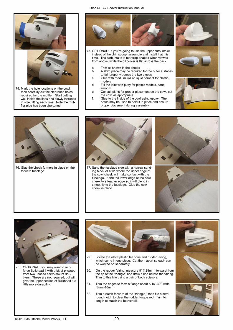
76. Glue the cheek formers in place on the forward fuselage.
77. Sand the fuselage side with a narrow sand-ing block or a file where the upper edge of the cowl cheek will make contact with the fuselage. Sand the lower edge of the cowl cheek to a feather edge so it will blend in smoothly to the fuselage. Glue the cowl cheek in place.
78. OPTIONAL: you may want to rein-force Bulkhead 1 with a bit of plywood from two unused servo mount dou-blers. These are not required, but will give the upper section of Bulkhead 1 a little more durability.
79. Locate the white plastic tail cone and rudder fairing, which come in one piece. Cut them apart so each can be worked on separately.
80. On the rudder fairing, measure 5” (128mm) forward from the tip of the “triangle” and draw a line across the fairing. Trim to this line using a pair of body scissors.
81. Trim the edges to form a flange about 5/16”-3/8” wide (8mm-10mm).
82. Trim a notch forward of the “triangle,” then file a semi-round notch to clear the rudder torque rod. Trim to length to match the beavertail.
75. OPTIONAL: If you’re going to use the upper carb intake instead of the chin scoop, assemble and install it at this time. The carb intake is teardrop-shaped when viewed from above, while the oil cooler is flat across the back.
a. Trim as shown in the photos
b. A shim piece may be required for the outer surfaces to fair properly across the two pieces
c. Glue with medium CA or liquid cement for plastic models
d. Fill the joint with putty for plastic models, sand smooth
e. Consult plans for proper placement on the cowl, cut the cowl as appropriate
f. Glue to the inside of the cowl using epoxy. The hatch may be used to hold it in place and ensure proper placement during assembly
74. Mark the hole locations on the cowl, then carefully cut the clearance holes required for the muffler. Start cutting well inside the lines and slowly increase in size, fitting each time. Note the muf-fler pipe has been shortened.
©2019 Moustache Model Works, LLC 30
20cc DHC-2 Beaver Instruction Manual
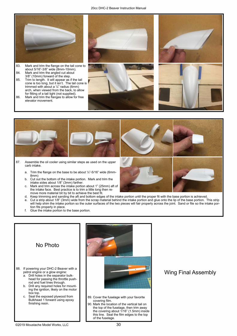
87. Assemble the oil cooler using similar steps as used on the upper carb intake.
a. Trim the flange on the base to be about ¼”-5/16” wide (6mm-
8mm) b. Cut out the bottom of the intake portion. Mark and trim the
intake sides about 1/8” (3mm) farther. c. Mark and trim across the intake portion about 1” (25mm) aft of
the intake face. Best practice is to trim a little long then re-move more material bit by bit to achieve the best fit.
d. Keep trimming and sanding the aft and bottom edges of the intake portion until the proper fit with the base portion is achieved. e. Cut a strip about 1/8” (3mm) wide from the scrap material behind the intake portion and glue onto the lip of the base portion. This strip
will help shim the intake portion so the outer surfaces of the two pieces will fair properly across the joint. Sand or file so the intake por-tion fits properly in place.
f. Glue the intake portion to the base portion.
88. If powering your DHC-2 Beaver with a petrol engine or a glow engine: a. Drill holes in the separator bulk-
head for passing the throttle push-rod and fuel lines through.
b. Drill any required holes for mount-ing the ignition, likely on the motor box top.
c. Seal the exposed plywood from Bulkhead 1 forward using epoxy finishing resin.
No Photo
89. Cover the fuselage with your favorite covering film.
90. Mark the location of the vertical tail on the top of the fuselage, then trim away the covering about 1/16” (1.5mm) inside this line. Seal the film edges to the top of the fuselage.
Wing Final Assembly
83. Mark and trim the flange on the tail cone to about 5/16”-3/8” wide (8mm-10mm).
84. Mark and trim the angled cut about 3/8” (10mm) forward of the step.
85. Trim to length. It will appear as if the tail cone is too long, but it isn’t. The tail cone is trimmed with about a ¼” radius (6mm) arch, when viewed from the back, to allow for fitting of a tail light (not supplied).
86. Mark and trim the flanges to allow for free elevator movement.
©2019 Moustache Model Works, LLC 31
20cc DHC-2 Beaver Instruction Manual
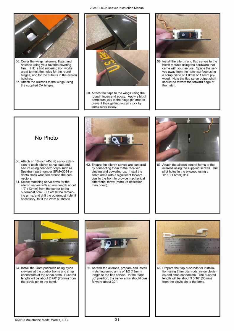
64. Install the 2mm pushrods using nylon clevises at the control horns and snap connectors at the servo arms. Pushrod length will be about 2 7/8” (73mm) from the clevis pin to the bend.
65. As with the ailerons, prepare and install matching servo arms of 1/2 (13mm) length to the flap servos. In the “flaps up” position, the servo arms should bias forward about 30°.
60. Attach an 18-inch (45cm) servo exten-sion to each aileron servo lead and secure using connector clips such as Spektrum part number SPMA3054 or dental floss wrapped around the con-nectors.
61. Select matching servo arms for the aileron servos with an arm length about 1/2” (13mm) from the center to the outermost hole. Cut off all the remain-ing arms, and drill the outermost hole, if necessary, to fit the 2mm pushrods.
No Photo
62. Ensure the aileron servos are centered by connecting them to the receiver, binding and powering-up. Install the servo arms with a significant forward bias to the front to provide mechanical differential throw (more up deflection than down).
63. Attach the aileron control horns to the ailerons using the supplied screws. Drill pilot holes in the plywood using a 1/16” (1.5mm) drill.
66. Prepare the flap pushrods for installa-tion using 2mm pushrods, nylon clevis-es and snap connectors. The pushrod length will be about 3 3/16” (80mm) from the clevis pin to the bend.
56. Cover the wings, ailerons, flaps, and hatches using your favorite covering film. Hint: a hot soldering iron works great to melt the holes for the round hinges, and for the cutouts in the aileron hatches.
57. Attach the ailerons to the wings using the supplied CA hinges.
58. Attach the flaps to the wings using the round hinges and epoxy. Apply a bit of petroleum jelly to the hinge pin area to prevent their getting frozen stuck by some stray epoxy.
59. Install the aileron and flap servos to the hatch mounts using the hardware that came with your servos. Space the ser-vos away from the hatch surface using a scrap piece of 1.0mm or 1.5mm ply-wood. Note the flap servo output shaft should be toward the forward edge of the hatch.

©2019 Moustache Model Works, LLC 32
20cc DHC-2 Beaver Instruction Manual
74. Bend the 3mm pushrods about 50mm from the threaded ends. The exact length required will depend on the length of the supplied clevises, so be sure to measure to make the overall strut length 16 3/8” (416mm). Cut to leave ¼” (6mm) of wire remaining after the bend.
75. Glue the pushrod ends in place on the struts with epoxy.
76. Cover the struts with iron-on covering, or finish in your preferred manner.
70. Install the wing strut mounts on the bottom of the wing, centered on the wing spar and with the inboard end 14 ¾” (375mm) from the root rib. The raised flange is on the forward edge. Drill 1/16” (1.5mm) pilot holes and use the 2.5mm x 10mm button head screws.
71. Assemble the struts using the airfoil-shaped pine and 3mm pushrods w/steel clevises and lock nuts. Overall length from clevis pin to clevis pin is 16 3/8” (416mm), while the length of the wood strut should be about 13 3/8” (340mm).
72. Drill 1/8” (3mm) holes into the leading edge of the struts, 1” (25mm) from each end, and about 5/16” (8mm) deep.
73. Cut grooves from those holes to the ends of the struts so the pushrod ends will recess into the struts, in the same fashion as were cut into the elevators and rudder. Use a hobby knife and a small, round file.
77. Assemble the struts to the fuselage & wings, adjusting the clevises to achieve the final, proper length. If you find any play in the wing tube/wing joint, we suggest you make the struts long enough to take up that play. In this manner, most of the wing loads will be absorbed by the wing tube.
78. Once the final strut length is found, use blue threadlock on the clevises to pre-vent the struts from rotating in flight. Short pieces of fuel tubing (1/4” long)can be used as keepers to securely keep the clevises closed.
No Photo
67. Tape the aileron extension to the shear web at the flap servo hatch to prevent it from interfering with the flap actuation.
68. Depending upon the length of your flap servo leads, you may need to attach a short extension (75mm or 3”) for it to reach the opening at the root rib. If required, do so now, and secure with a connector clip or dental floss.
69. Connect the pushrod to the flap horn and test the fit of the hatch mount in place on the wing. You will need to adjust your servo throw in the transmitter and/or adjust the length of the pushrod to get the hatch mount to fit properly. TO AVOID DAMAGING THE SERVO, PUSHROD, OR HATCH, DON’T POWER-ON YOUR RECEIVER & TRANSMITTER WITH THE HATCH MOUNT SCREWED IN PLACE UNTIL THE PROPER FIT IS ACHIEVED! AFTER the hatch is properly fitted, then screw the hatch in place.

©2019 Moustache Model Works, LLC 33
20cc DHC-2 Beaver Instruction Manual
9. Install the rudder fairing and the tail cone using double-sided tape.
10. Assemble and install the fuel tank with a hook-and-loop strap and a piece of ½” (12mm) latex foam rubber as insula-tion against vibration (fuel tank and strap not included). Drill pass-through holes in the engine separator bulkhead for the fuel lines, offset from center if using a rear-carb engine such as the DLE-20.
5. Remove the pushrod, bend at the mark, install onto the servo arm using a snap connector and cut to length.
6. Repeat steps 4 and 5 for the elevator pushrod.
7. Glue the vertical stab & rudder to the fuselage before installing the horizontal stab. First install a 3mm nut on the rudder pushrod and adjust the clevis by turning in or out to center the rudder with the servo centered. Once satisfied, tighten the nut, connect the pushrod to the rudder and glue the vertical stab into place using epoxy. Site from front and rear to assure vertical alignment.
8. Check the fit of the horizontal stab and elevators. A slight groove may be re-quired in HS-9 to clear the rudder torque rod. Check for symmetrical alignment with the wingtips in addition to sighting for level from front and be-hind, then glue in place using epoxy. Once glued, connect and adjust the elevator pushrod.
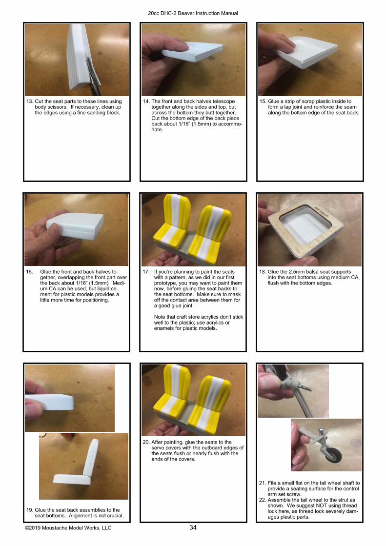
11. Rough-cut the seat parts leaving about a ¼” (6mm) flange.
12. Using a sharp pencil flat on the table, mark the trim line for all the parts. This is easy if you hold the pencil still and move the part around it, both flat on the table.
Fuselage/Overall Final Assembly
Most of these steps do not need to be completed in any particular or-der.
You may find it easier to do the tail installation with the main gear in-stalled.
1. Install/reinstall the elevator and rudder servos into the fuselage, output shaft biased aft.
2. Select a servo arm that’s about 1 ¼” – 1 3/8” (32mm – 35mm) across for the rudder servo. Remove the excess arms and drill the third hole from the outside to accept the 3mm pushrod.
3. Select a servo arm that’s about 9/16” (15mm) from the center shaft to the outermost hole for the elevator ser-vo and drill the outermost hole for the 3mm pushrod.
4. Assemble a clevis onto the rudder push-rod and slide the pushrod through the guide tube. Attach the clevis to the rudder and set the vertical stab & rudder in place on the fuselage. With the rud-der centered, mark the pushrod for bending at the servo arm.
©2019 Moustache Model Works, LLC 34
20cc DHC-2 Beaver Instruction Manual
19. Glue the seat back assemblies to the seat bottoms. Alignment is not crucial.
20. After painting, glue the seats to the servo covers with the outboard edges of the seats flush or nearly flush with the ends of the covers.
16. Glue the front and back halves to-gether, overlapping the front part over the back about 1/16” (1.5mm). Medi-um CA can be used, but liquid ce-ment for plastic models provides a little more time for positioning.
17. If you’re planning to paint the seats with a pattern, as we did in our first prototype, you may want to paint them now, before gluing the seat backs to the seat bottoms. Make sure to mask off the contact area between them for a good glue joint.
Note that craft store acrylics don’t stick well to the plastic; use acrylics or enamels for plastic models.
18. Glue the 2.5mm balsa seat supports into the seat bottoms using medium CA, flush with the bottom edges.
21. File a small flat on the tail wheel shaft to provide a seating surface for the control arm set screw.
22. Assemble the tail wheel to the strut as shown. We suggest NOT using thread lock here, as thread lock severely dam-ages plastic parts.
14. The front and back halves telescope together along the sides and top, but across the bottom they butt together. Cut the bottom edge of the back piece back about 1/16” (1.5mm) to accommo-date.
15. Glue a strip of scrap plastic inside to form a lap joint and reinforce the seam along the bottom edge of the seat back.
13. Cut the seat parts to these lines using body scissors. If necessary, clean up the edges using a fine sanding block.
©2019 Moustache Model Works, LLC 35
20cc DHC-2 Beaver Instruction Manual
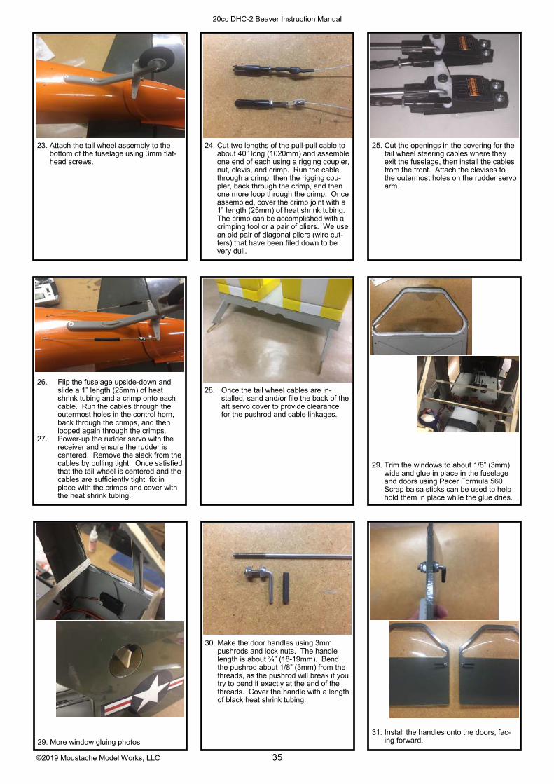
29. More window gluing photos
30. Make the door handles using 3mm pushrods and lock nuts. The handle length is about ¾” (18-19mm). Bend the pushrod about 1/8” (3mm) from the threads, as the pushrod will break if you try to bend it exactly at the end of the threads. Cover the handle with a length of black heat shrink tubing.
26. Flip the fuselage upside-down and slide a 1” length (25mm) of heat shrink tubing and a crimp onto each cable. Run the cables through the outermost holes in the control horn, back through the crimps, and then looped again through the crimps.
27. Power-up the rudder servo with the receiver and ensure the rudder is centered. Remove the slack from the cables by pulling tight. Once satisfied that the tail wheel is centered and the cables are sufficiently tight, fix in place with the crimps and cover with the heat shrink tubing.
28. Once the tail wheel cables are in-stalled, sand and/or file the back of the aft servo cover to provide clearance for the pushrod and cable linkages.
29. Trim the windows to about 1/8” (3mm) wide and glue in place in the fuselage and doors using Pacer Formula 560. Scrap balsa sticks can be used to help hold them in place while the glue dries.
31. Install the handles onto the doors, fac-ing forward.
24. Cut two lengths of the pull-pull cable to about 40” long (1020mm) and assemble one end of each using a rigging coupler, nut, clevis, and crimp. Run the cable through a crimp, then the rigging cou-pler, back through the crimp, and then one more loop through the crimp. Once assembled, cover the crimp joint with a 1” length (25mm) of heat shrink tubing. The crimp can be accomplished with a crimping tool or a pair of pliers. We use an old pair of diagonal pliers (wire cut-ters) that have been filed down to be very dull.
25. Cut the openings in the covering for the tail wheel steering cables where they exit the fuselage, then install the cables from the front. Attach the clevises to the outermost holes on the rudder servo arm.
23. Attach the tail wheel assembly to the bottom of the fuselage using 3mm flat-head screws.

©2019 Moustache Model Works, LLC 36
20cc DHC-2 Beaver Instruction Manual
39. Install the oil cooler using either double-sided tape or medium CA. Refer to the plans for positioning.
40. After painting the LG fairings and main gear, install the landing gear axle shafts to the aluminum main gear using the included lock nut.
41. Install your wheels of choice. Scale size for standard wheels is 3 ¾” (95mm), and scale size for tundra tires is 4 ½ - 5 ½” (115-140mm). Shown are 5” Dubro tundra tires.
35. Fit the upper half of the fairing in place. Cut a clearance slot to provide access to the fuselage strut mount.
36. Once satisfied with the fit of the LG Ribs and fairings, glue the ribs in place on the gear using medium CA.
37. Glue the fairing lower half in place using a mixture of epoxy and microballoons applied to the LG Ribs.
38. Glue the fairing upper half in place also using a mixture of epoxy and microbal-loons applied to the ribs and the leading and trailing edges of the fairing.
42. Assemble the airplane completely and check cg. CG has been tested between 2 ¾” and 3 ¼” (70mm – 83mm) aft of the leading edge, measured outboard of the taper at the root LE. This equates to 28% - 33% of MAC. CG is easiest to measure at the flap servo cover.
As CG moves aft, the stall results in more wing drop, but the Beaver recov-ers quickly. There is no one “right” cg! The right cg is the one that yields the flight characteristics the pilot prefers.
33. Slide the upper and lower LG Ribs onto the landing gear and tape in place. The lower LG Rib should be right at the end of the fairing and the upper Rib should be as shown in the photos. Exact placement is not required.
34. Fit the lower half of the gear fairings in place and note where the LG Ribs need to be trimmed and sanded for a proper fit. Also note the lower fairing will need to be trimmed to clear the float mounts. The fairings were designed to have about 1/16” (1.5mm) clearance from the fuselage. (The photos show 3D printed prototype fairings, but the included fiber-glass fairings fit the same)
32. Install the main gear using the 5mm socket head cap screws and washers. The matching holes in the aluminum main gear are drilled and tapped for M5 screws.

©2019 Moustache Model Works, LLC 37
20cc DHC-2 Beaver Instruction Manual
Control Throws and Programming
Elevator: 1” (25mm) Up 3/4” (19mm) Down
Ailerons: 1” (25mm) Up 3/8” (10mm) Down
Rudder: 1 1/4” (32mm) Right and Left
Flaps: ~20° Mid 50°- 60° Full
Flap → Elevator Mixing: Mid = 20%, Full = 30%
Aileron → Rudder Mixing: 35% Right and Left
Aileron Differential: 50%
These values are high-rate throws, select lower rates to taste. The first prototype is flown with high rates, which provide a very comfortable level of control without being too sensitive to stick inputs. As of this writ-ing, about two dozen pilots have flown the Beaver using these rates, and not one of them ever switched to lower rates.
Aileron → Rudder Mixing is of course a matter of taste. You may want more or less depending on how much rudder you want to input manually during turns.
Aileron differential, which means less downward throw than upward throw, is necessary to combat ad-verse yaw. Adverse yaw means the airplane yaws the opposite direction of a roll input, even though it rolls in the right direction. It’s caused when the drag of the lowered aileron is much higher than the drag of the raised aileron. High aspect ratio wings with “barn door” ailerons traditionally exhibit significant adverse yaw effects, and this Beaver is no exception. The impact is highly uncoordinated turns. Adverse yaw is corrected by both aileron differential and aileron → rudder mixing, but aileron → rudder mixing can impact aerobatic performance, especially during rolling maneuvers. Using a lot of aileron differential can help re-duce the amount of mixing required, thus minimizing the impact to aerobatics. For this reason, we have used both mechanical differential by angling the aileron servo horns forward, and electronic differential through computer transmitter programming.
Flying
During takeoff, apply throttle slowly and smoothly. Hold a little up elevator from the beginning to keep the tail wheel on the ground and maintain steering control until the rudder sees enough airspeed to become effective, especially on pavement. Often this approach results in a three-point takeoff, as the Beaver doesn’t need much airspeed to fly. With the Power 60, 400Kv on 6S, most takeoffs happen at 50% throt-tle. We prefer using mid flaps for takeoff.
In the air, trim the elevator to maintain level flight at 50% throttle. This way she will gain altitude gently when you increase throttle and lose altitude gently when you decrease throttle. The Beaver is very com-fortable at that medium speed, which looks quite scale in the air.
Take her up to altitude and perform some stalls to get a feel for how she wants to behave. The first proto-type is nearly impossible to stall at the forward CG location, while at the aft location, she will drop a wing about 30% - 40% of the time. Stall happens at a very low airspeed, and recovery is always fast, so even the aft CG location has manageable handling qualities. With mid flaps, even at the aft CG location stall is difficult to achieve.
The flaps are hugely effective, but require significant elevator mixing. When he flew it, Mike McConville said mid flaps make it “buoyant,” which seems appropriate. At full flaps, she nearly stops in the air, mak-ing super-slow landing the norm. Deploying full flaps in the middle of a loop or at the beginning of a split-S, then going right into a landing or even a crabbed landing is a blast.
For landing, use full flaps most of the time, or mid flaps if there is a lot of wind, especially crosswind. Both wheel landings and three-point landings are appropriate.

©2019 Moustache Model Works, LLC 38
20cc DHC-2 Beaver Instruction Manual
What’s Included
Wood Item Size Qty. Notes
Lite Ply 3mm x 12” x 48” 4 Fuselage Parts
Birch Ply
.5mm x 6” x 24” 1 Empennage, Cowl Cheeks
1mm x 12” x 24” 1 Door Reinforcement, Tail Tip Ribs
1.5mm x 12” x 24” 1 Wing Servo Mounting, Shear Webs
6mm x 12” x 12” 1 Firewall, Engine Rails, Bulkhead 3
Balsa Sheet - Laser Cut
1.5mm x 4” x 36” 6 Empennage Sheeting, Wing Shear Webs
2.5mm x 4” x 36” 10 Wing & Tail Ribs, Flap & Ail Sheeting
6mm x 4” x 36” 1 Empennage Spars, tips, etc
6mm x 3” x 36” 1 Flap LE
6mm x 3” x 48” 1 Wing Trailing Edges
Balsa Sheet - Not Laser Cut
2.5mm x 3” x 48” 4 Wing LE Sheeting
2.5mm x 4” x 48” 1 Wing Center Sheeting
2.5mm x 2” x 36” 3 Pre– formed Fuse Lower Corners
2.5mm x 3/4” x 48” 4 Wing TE Sheeting
2.5mm x 3/8” x 36” 5 Cap Strips
10mm x 1 3/4” x 36” 2 Fuse Top Corner
3mm x 4” x 6” 1 Fwd Cockpit Roof - Grain in long direction
Balsa Stick
6mm triangle x 36” 2 Flap LE
13mm triangle x 36” 2 Flap Upper Fairing
10mm x 1” x 48” 2 Wing LE
10mm x 3/4” x 36” 1 Aileron LE
6mm x 3/8” x 36” 1 Stab LE
6mm x 13mm x 8” 1 Cockpit Roof Support
5mm x 13mm x 48” 4 Wing Spars
Pine 10mm x 15 mm x 14” 2 Wing Struts - Airfoil Shape
Bag 1, Wing
Hardware
Item Qty
2mm Pushrod for Flaps & Ailerons 4
3mm Pushrod for Wing Struts 4
3mm Steel Clevis 4
3mm Clevis retaining nut 4
1/4-20 Wing Bolt, Nylon thumb screw 2
1/4-20 Blind Nut for Wing Attach 2
2mm x 10mm Button head screw for servo hatches
16
2mm Nylon Clevis 4
2mm Nylon Swing Keeper 4
CA Hinges 6
2.5mm Round Hinges 6
Nylon Control Horn w/attach screws 2
Aluminum Wing Strut Mounts 2
Button-head Screw for wing strut mounts 4
Hardwood Dowel for wing anti-torque 2
Item Qty
Bag 2, Tail
Hardware
CA Hinges 11
Stab Joiner / control horn 1
Rudder Torque Rod 1
3mm Steel Clevis 2
Clevis retaining nuts 2
3mm Nylon swing keeper 2
Pull-Pull Cable Set, with cable (2m), 4 crimps, 2mm steel clevises x 2, 2mm nut x 2, 2mm cable end x 2
1
Item Qty
Bag 3, Fuselage
And Landing
Gear
Tail Wheel Assembly 1
3mm Blind nuts for Tail Wheel Mounting 2
3mm Flat Head Machine Screws 2
5mm Socket Head Cap Screws 6
5mm Washers for LG Mounting Screws 6
2mm Round Hinges for doors 4
5mm Steel Axle Shaft with lock nut 2
3mm Pushrod for door handles 2
3mm Lock Nuts for door handles 4
Hardwood Dowel for hatch retaining 2

©2019 Moustache Model Works, LLC 39
20cc DHC-2 Beaver Instruction Manual
Item Qty
Bag 3, Fuselage
And Landing
Gear
Tail Wheel Assembly 1
3mm Blind nuts for Tail Wheel Mounting 2
3mm Flat Head Machine Screws 2
5mm Socket Head Cap Screws 6
5mm Washers for LG Mounting Screws 6
2mm Round Hinges for doors 4
5mm Steel Axle Shaft with lock nut 2
3mm Pushrod for door handles 2
3mm Lock Nuts for door handles 4
Hardwood Dowel for hatch retaining 2
BAG 4, Float and Strut Attach Parts
Item Qty
4-40 Blind Nuts 16
4-40 x 3/8” Socket Head Cap Screws 16
Fuselage Strut Mounts, .063 aluminum 2
Float Mount 1, .063 aluminum 2
Float Mount 2/3, .063 aluminum 4
Float Mount 4, .063 aluminum 2
BAG 5, Motor and other Fuse-lage
Item Qty
4mm Blind Nuts for Motor Mount (gas or electric)
4
4mm x 15mm Socket Head Cap screws for Electric Motor mounting
4
4mm x 25mm Socket Head Cap Screws for gas or glow Engine Mounting
4
4mm Split Washers for Engine Mounting Screws
4
4-40 x 3/8” Socket Head Cap Screws for Cowl attachment
4
4-40 Blind Nuts for cowl attachment 4
6mm Magnets - Seat Attachments, Doors 12
10mm Magnets - Hatch 4
BAG 6, Long Parts
Item Qty
Cardboard Tube - Sleeve for wings - 20mm ID x 9 5/8”
2
Cardboard Tube - Sleeve for fuselage - 20mm x 8 1/16”
1
Carbon Fiber Wing Tube 1
Elevator Pushrod, 3mm x 35 1/8” 1
Rudder Pushrod, 3mm x 35 1/8” 1
Clear Plastic 5mm Pushrod Guide Tube 2
Clear Plastic 3mm Tailwheel Cable Guide 2
Fiberglass Parts
Cowl Landing gear fairings, 4 pcs
Wing Tips, Left and Right
Plastic Parts
Windshield hatch, 1 sheet clear Windows, 1 sheet clear Tail Cone / Rudder Fairing, 1 sheet white
Upper Carb Intake / Oil Cooler, 1 sheet white
Seats, 2 sheets white
Aluminum Main Landing Gear, 2 pcs

Moustache Model Works, LLC
PO Box 916
Mahomet, IL 61853
www.moustachemodelworks.com